

Page 1
Type 400 Single Mount Housing
C A U T I O N !
SUBJECT TO ELECTROSTATIC DAMAGE
OR DECREASE IN RELIABILITY.
HANDLING PRECAUTIONS REQUIRED.
For Loop Powered Network Termination Units
Installation and Maintenance
CONTENTS
1. GENERAL..........................................................1
2. INSTALLATION ............................................... 1
3. CONNECTIONS ................................................ 2
4. MAINTENANCE...............................................3
5. WARRANTY AND CUSTOMER SERVICE... 3
FIGURES
Figure 1. T400 LP Housing ......................................1
Figure 2. T400 LP Housing with Cover Open .........2
Figure 3. T400 LP Housing Rear Panel....................2
TABLES
Table 1. Cable Pairs ................................................ 2
Table 2. Barrier Strip Interface Connection to Card
Edge Connector ......................................... 2
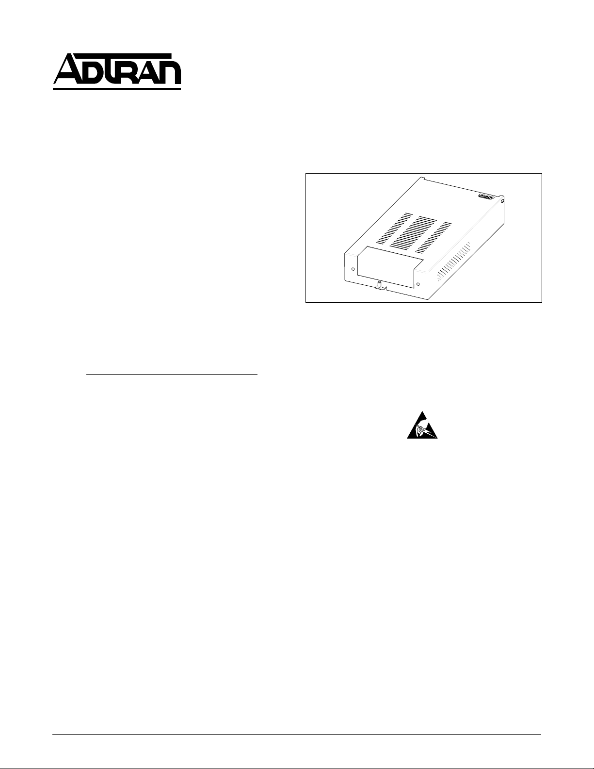
1. GENERAL
This section provides installation and maintenance
information for the ADTRAN
Single Mount Housing, illustrated in Figure 1.
®
Type 400 (T400)
Section 61212007L1-5B
Issue 2, May 2001
CLEI Code # NCM5MPSD_ _
Figure 1. T400 LP Housing
• Span Powered
• Network connection via terminal barrier strip
• Customer connects to RJ-48 or barrier strip
• Durable metal enclosure
2. INSTALLATION
Description
The ADTRAN T400 housing is used with a Loop
Powered (LP) Type 400 network termination unit and
is located at the customers premises. Functioning as a
point-of-demarcation, the combination housing and
circuit pack provide diagnostic and provisioning
information useful in installation and trouble isolation
procedures.
Connections are made to the unit by a screw terminal
block and an RJ-48 jack.
Document Revision History
This document has been revised to include additional
grounding information.
Features
The ADTRAN T400 LP Housing, P/N 1212007L1,
features include:
• Standalone Type-400 housing
61212007L1-5B
After unpacking the unit, inspect it for damage. If
damage is discovered, file a claim with the carrier and
then contact ADTRAN. See Warranty and Customer
Service.
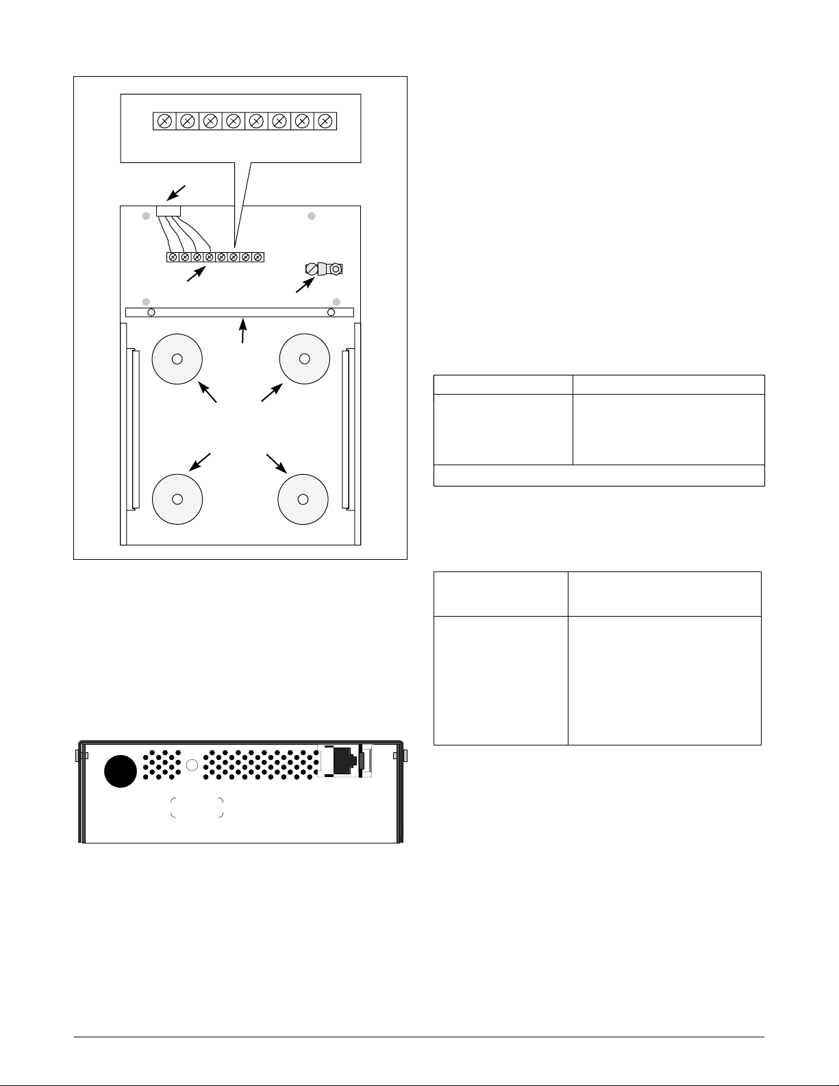
The ADTRAN T400 LP housing may be mounted
using the mounting holes shown in Figure 2.
Open the cover and insert the circuit card through the
front of the housing until it snaps into the card edge
connector (J1), shown in Figure 2. After making the
interface connections and lowering and securing the
cover, the unit is ready for normal operation. Some
circuit cards may require a frame ground connection
to pin 11 or 27 of the gold finger connector. A ground
lug (L1), as illustrated in Figure 2, is provided to
connect an external frame ground wire to the unit.
Trademarks: Any brand names and product names included in this document are
trademarks, registered trademarks, or trade names of their respective holders.
Section 61212007L1-5, Issue 2
1
Page 2
81
P1
DRR
DRT
DTT
DTR
TR
TT
RR
RT
Modular Connector
RJ-48
8 7 2 1
3. CONNECTIONS
The barrier strip provides screw-down terminals for
network and customer signal interfaces. Customerside connections are usually made through the RJ-48
connector which is prewired to the barrier strip. To
connect to the barrier strip, conductors should be
placed beneath the square washer of each screw
terminal and tightened. Table 1 provides cable pair
connections and descriptions.
Terminal
Barrier
Strip
P1
J1
Card Edge
Connector
Mounting
Holes
Frame
Ground
Lug
L1
Figure 2. T400 LP Housing with Cover Open
The ground lug provides an external Frame Ground
connection for pins 11 and 27 of the plugin’s gold
finger card edge. Insert the grounding wire into the
housing through the Network portal of the rear panel,
as illustrated in Figure 3.
The T400 LP housing is compatible with other looppowered T400 units. Table 2 describes the terminal
barrier strip and circuit card gold finger connector
interface signal assignments.
Table 1. Cable Pairs
Pair* Description
RT, RR
TT , TR
DRT, DRR
DTT, DTR
From Network
To Network
To Customer
From Customer
* The conductors of each pair are not polarity sensitive.
Table 2. Barrier Strip Interface Connection to
Card Edge Connector
Terminal Barrier
Strip (P1)
DRT
RT
RR
DRR
TT
TR
DTR
DTT
Circuit Card Gold Finger
Connector
5
7
13
15
41
47
49
55
NETWORK
Figure 3. T400 LP Housing Rear Panel
2
CUSTOMER
Section 61212007L1-5, Issue 2
61212007L1-5B
Page 3

4. MAINTENANCE
The Model T400 LP housing does not require
maintenance to operate properly. In case of
equipment failure, remove the unit and replace it with
another unit.
ADTRAN recommends that repairs on the unit not be
performed in the field. Repair services may be
obtained by returning damaged units to ADTRAN.
5. WARRANTY AND CUSTOMER SERVICE
ADTRAN will replace or repair this product within
ten years from the date of shipment if it does not meet
its published specifications or fails while in service
(see ADTRAN Carrier Networks Equipment
Warranty, Repair, and Return Policy and Procedure,
document 60000087-10).
Return Material Authorization (RMA) is required
prior to returning equipment to ADTRAN.
For service, RMA requests, or further information,
contact one of the following numbers:
ADTRAN Sales
Pricing and availability
(800) 827-0807
ADTRAN Technical Support
Pre-sales Applications/Post-sales Technical Assistance
(800) 726-8663
Standard hours: Monday - Friday, 7 a.m. - 7 p.m. CST
Emergency hours: 7 days/week, 24 hours/day
ADTRAN Repair/CAPS
Return for repair / upgrade
(256) 963-8722
Repair and Return Address:
ADTRAN, Inc.
CAPS
901 Explorer Boulevard
Huntsville, Alabama 35806-2807
61212007L1-5B
Section 61212007L1-5, Issue 2
3
Page 4

4
Section 61212007L1-5, Issue 2
61212007L1-5B
 Loading...