

Page 1

657"4/"YKVJ"8057
2CTV"0WODGT"3424299.3
&QEWOGPV"0WODGT"83424299.3/42#
,WPG"3;;;
Page 2

901 Explorer Boulevard
P.O. Box 140000
Huntsville, AL 35814-4000
Phone: (256) 963-8000
© 1999 ADTRAN, Inc.
All rights reserved.
Printed in USA.
Page 3

ADTRAN Year 2000 (Y2K) Readiness Disclosure
ADTRAN has established a Year 2000 program to ensure that our products will correctly function in the new millennium. ADTRAN warrants
that all products meet Y2K specifications regardless of model or revision.
Information about ADTRAN’s Y2K compliance program is available at
the following locations:
ADTRAN Web Site
Product Matrix
Faxback Document
Line
Y2K Project Line
E-mail
www .adtran.com
www .adtran.com/y2kfax.html
(256) 963-8200
Y2K plans and product certifications are
listed in the matrix
(256) 963-2200
year2000@adtran.com
.
iii
Page 4

FCC regulations require that the following information be provided to the customer in this manual.
1. This equipment complies with Part 68 of the FCC rules. The
required label is attached to the bottom of the chassis.
2. If your TSU RM causes harm to the telephone network, the Telephone Company may discontinue your service temporarily. If
possible, they will notify you in advance. If advance notice is not
practical, you will be notified as soon a s possible. You will be
advised of your right to file a complaint with the FCC.
3. Your telephone company may make changes in its facilities,
equipment, operations, or procedur es that could af fect the proper
operation of your equipment. If they do, you will be given
advance notice so as to give you an opportunity to maintain
uninterrupted service.
4. If you experience trouble with the TSU RM, please contact
ADTRAN at (256) 963-8000 for repair/ warranty information.
The telephone company may ask you to disconnect th is equipment from the network until the problem has been corrected, or
until you are sure the equipment is not malfunctioning.
5. This unit contains no user serviceable parts.
6. An FCC compliant telephone cord and modular plug is provided
with this equipment. This equipment is designed to be connected to the telephone network or premises wiring using a compatible modular jack which is Part 68 compliant. See installation
instructions for details.
7. The following information may be required when applying to
your local telephone company for leased line facilities.
Service Type SOC FIC USOC
1.544 Mbps - SF 6.0F 04DU9-BN RJ48C
1.544 Mbps - SF and B8ZS 6.0F 04DU9-DN RJ48C
1.544 Mbps - ESF 6.0F 04DU9-1KN RJ48C
1.544 Mbps - ESF 6.0F 04DU9-1SN RJ48C
iv
Page 5

FEDERAL COMMUNICATIONS COMMISSION
RADIO FREQUENCY INTERFERENCE STATEMENT:
This equipment has been tested and found to comply with the limits for
a Class A digital device, pursuant to Part 15 of the FCC Rules. These
limits are designed to provide reasonable protection against harmful
interference when the equipment is operated in a commercial environment. This equipment generates, uses, and can radiate radio frequency
energy and, if not installed and used in accordance with the instruction
manual, may cause harmful interference to radio frequencies. Operation of this equipment in a residential area is likely to cause harmful
interference, in which case the user will be required to correct the interference at his own expense.
Shielded cables must be used with this unit to ensure compliance with
Class A FCC limits.
Changes or modifications to this unit not expressly approved by
the party responsible for compliance could void the user’s authority to operate the equipment.
v
Page 6

CANADIAN EQUIPMENT LIMITATIONS
The Industry Canada Certification label identifies certified equipment. This certification means that the
equipment meets certain telecommunications network
protective, operational, and safety requirement s. The
Department does not guarantee the equipment will operate to the user's satisfaction.
Before installing this equipment, users should ensure that it is permissible to be connected to the facilities of the local telecommunications company. The equipment must also be installed using an
acceptable method of connection. In some cases, the company's
inside wiring associated with a single line individual service may be
extended by means of a certified connector assembly (telephone
extension cord). The c ustomer should be aware that compliance with
the above conditions may not preven t degrad ation of service in some
situations.
Repairs to certified equipment should be made by an authorized
Canadian maintenance facility designated by the supplier. Any
repairs or alterations made by the user to this equipment, or equipment malfunct ions, may give th e telecommuni cations compan y cause
to request the user to disconnect the equipment.
Users should ensure for their own protection that the electrical
ground connections of the power utility, telephone lines and internal
metallic waterpipe system, if present, are connected together. This
precaution may be particularly important in rural areas.
Users should not attempt to make such connections themselves, but should contact the appropriate electric inspection
authority, or an electrician, as appropriate.
vi
Page 7

IMPORTANT SAFETY INSTRUCTIONS
When using telephone equipment, please follow these basic
safety precautions to reduce the risk of fire, electrical shock,
or personal injury
1. Do not use this product near water, such as a bathtub, wash bowl,
kitchen sink, laundry tub, in a wet basement, or a swimming pool.
2. Avoid using a telephone (other than a cordless type) during an electrical storm. There is a remote risk of shock from lightning.
3. Do not use the telephone to report a gas leak in the vicinity of the
leak.
4. Use only the power cord, power supply, and/or batteries indicated
in the manual. Do not dispose of batteries in a fire. They may
explode. Check with local codes for special disposal instructions.
SAVE THES E IN STRUC TI ON S
vii
Page 8

Warranty and Customer Service
ADTRAN will replace or repair this product within five years from
the date of shipment if the product does not meet its published specifications or if it fails while in service. For detailed warranty, repair,
and return information, see the ADTRAN Equipment Warranty and
Repair and Return Policy Procedure.
Return Material Authorization (RMA) is required prior to returning
equipment to ADTRAN.
For Service, RMA requests, or more information, contact one of the
numbers found at the inside back page of this manual.
viii
Page 9

Table of Contents
List of Figures . . . . . . . . . . . . . . . . . . . . . . . . . . . . . . . . xi
Chapter 1 Introduction . . . . . . . . . . . . . . . . . . . . . . . . . . . . . . . . . 1-1
General Description . . . . . . . . . . . . . . . . . . . . . . . . . . . . . . . . . . . . . . 1-1
Chapter 2 Physical Description . . . . . . . . . . . . . . . . . . . . . . . . . . 2-1
Front Panel. . . . . . . . . . . . . . . . . . . . . . . . . . . . . . . . . . . . . . . . . . . . . . 2-1
OK Status (green) . . . . . . . . . . . . . . . . . . . . . . . . . . . . . . . . . . . . . . 2-2
DTE Status (green) . . . . . . . . . . . . . . . . . . . . . . . . . . . . . . . . . . . . . 2-2
TD . . . . . . . . . . . . . . . . . . . . . . . . . . . . . . . . . . . . . . . . . . . . . . . . . 2-2
RD . . . . . . . . . . . . . . . . . . . . . . . . . . . . . . . . . . . . . . . . . . . . . . . . . 2-2
RS . . . . . . . . . . . . . . . . . . . . . . . . . . . . . . . . . . . . . . . . . . . . . . . . . 2-2
CS . . . . . . . . . . . . . . . . . . . . . . . . . . . . . . . . . . . . . . . . . . . . . . . . . 2-2
Error/Alarm Status (red) . . . . . . . . . . . . . . . . . . . . . . . . . . . . . . . 2-2
ERR . . . . . . . . . . . . . . . . . . . . . . . . . . . . . . . . . . . . . . . . . . . . . . . . 2-2
ALM . . . . . . . . . . . . . . . . . . . . . . . . . . . . . . . . . . . . . . . . . . . . . . . 2-2
Loopback Status (yellow) . . . . . . . . . . . . . . . . . . . . . . . . . . . . . . . 2-3
LB . . . . . . . . . . . . . . . . . . . . . . . . . . . . . . . . . . . . . . . . . . . . . . . . . 2-3
Dial Backup Status (yellow) . . . . . . . . . . . . . . . . . . . . . . . . . . . . . 2-3
DBU . . . . . . . . . . . . . . . . . . . . . . . . . . . . . . . . . . . . . . . . . . . . . . . 2-3
REAR PANEL . . . . . . . . . . . . . . . . . . . . . . . . . . . . . . . . . . . . . . . . 2-4
Chapter 3 Installation . . . . . . . . . . . . . . . . . . . . . . . . . . . . . . . . . . 3-1
Unpacking . . . . . . . . . . . . . . . . . . . . . . . . . . . . . . . . . . . . . . . . . . . . . . 3-1
Powering . . . . . . . . . . . . . . . . . . . . . . . . . . . . . . . . . . . . . . . . . . . . . . . 3-1
Network and DTE Connections . . . . . . . . . . . . . . . . . . . . . . . . . . . . 3-2
Network Connections . . . . . . . . . . . . . . . . . . . . . . . . . . . . . . . . . . 3-2
DTE Connections . . . . . . . . . . . . . . . . . . . . . . . . . . . . . . . . . . . . . . 3-3
Chapter 4 Operation. . . . . . . . . . . . . . . . . . . . . . . . . . . . . . . . . . . . 4-1
Menu Structure . . . . . . . . . . . . . . . . . . . . . . . . . . . . . . . . . . . . . . . . . . 4-2
Configuration Menu. . . . . . . . . . . . . . . . . . . . . . . . . . . . . . . . . . . . . . 4-3
Network Options . . . . . . . . . . . . . . . . . . . . . . . . . . . . . . . . . . . . 4-5
DTE/Other Options . . . . . . . . . . . . . . . . . . . . . . . . . . . . . . . . . . 4-7
61202077L1-20 TSU RM with V.35 User Manual ix
Page 10

Table of Contents
Test Menu . . . . . . . . . . . . . . . . . . . . . . . . . . . . . . . . . . . . . . . . . . . . . 4-13
Local Unit . . . . . . . . . . . . . . . . . . . . . . . . . . . . . . . . . . . . . . . . . . . . 4-15
Run Self-Test . . . . . . . . . . . . . . . . . . . . . . . . . . . . . . . . . . . . . . .4-15
Local Loopbacks . . . . . . . . . . . . . . . . . . . . . . . . . . . . . . . . . . . .4-15
Remote Unit . . . . . . . . . . . . . . . . . . . . . . . . . . . . . . . . . . . . . . . . . . 4-17
Remote Loopbacks . . . . . . . . . . . . . . . . . . . . . . . . . . . . . . . . . . 4-17
Test Patterns . . . . . . . . . . . . . . . . . . . . . . . . . . . . . . . . . . . . . . . . 4-18
DBU Tests . . . . . . . . . . . . . . . . . . . . . . . . . . . . . . . . . . . . . . . . . .4-18
Status Menu . . . . . . . . . . . . . . . . . . . . . . . . . . . . . . . . . . . . . . . . . . . 4-19
Status Display Explanation . . . . . . . . . . . . . . . . . . . . . . . . . . . . . 4-22
Status Displays . . . . . . . . . . . . . . . . . . . . . . . . . . . . . . . . . . . . . . 4-22
DATAMATE Status . . . . . . . . . . . . . . . . . . . . . . . . . . . . . . . . . . 4-22
Utility Menu . . . . . . . . . . . . . . . . . . . . . . . . . . . . . . . . . . . . . . . . . . . 4-26
Factory Restore . . . . . . . . . . . . . . . . . . . . . . . . . . . . . . . . . . . . . . . 4-27
Software Rev . . . . . . . . . . . . . . . . . . . . . . . . . . . . . . . . . . . . . . . . . 4-28
Time/Date . . . . . . . . . . . . . . . . . . . . . . . . . . . . . . . . . . . . . . . . . . . 4-28
From Datamate . . . . . . . . . . . . . . . . . . . . . . . . . . . . . . . . . . . . .4-28
From Terminal . . . . . . . . . . . . . . . . . . . . . . . . . . . . . . . . . . . . . .4-28
Dial Backup (DBU) Utilities . . . . . . . . . . . . . . . . . . . . . . . . . . . . .4-29
Force DBU . . . . . . . . . . . . . . . . . . . . . . . . . . . . . . . . . . . . . . . . . .4-29
Forced Restore . . . . . . . . . . . . . . . . . . . . . . . . . . . . . . . . . . . . . .4-29
Appendix A Specifications . . . . . . . . . . . . . . . . . . . . . . . . . . . . . A-1
Index . . . . . . . . . . . . . . . . . . . . . . . . . . . . . . . . . . . .Index-1
x TSU RM with V.35 User Manual 61202077L1-20
Page 11

List of Figures
Figure 1-1. TSU Network Diagram. . . . . . . . . . . . . . . . . . . . . . . . 1-2
Figure 2-1. TSU Front Panel . . . . . . . . . . . . . . . . . . . . . . . . . . . . . . 2-1
Figure 2-2. TSU Rear Panel . . . . . . . . . . . . . . . . . . . . . . . . . . . . . . . 2-4
Figure 4-1. Display of Terminal Main Menu . . . . . . . . . . . . . . . . 4-2
Figure 4-2. Display of DATAMATE Main Menu. . . . . . . . . . . . . 4-2
Figure 4-3. Display of Terminal Configuration Menu . . . . . . . . 4-3
Figure 4-4. DATAMATE Configuration Menu Tree. . . . . . . . . . 4-4
Figure 4-5. Display of Terminal Test Menu . . . . . . . . . . . . . . . . 4-13
Figure 4-6. Display of Terminal Test Results . . . . . . . . . . . . . . . 4-13
Figure 4-7. DATAMATE Test Menu Tree. . . . . . . . . . . . . . . . . . 4-14
Figure 4-8. DATAMATE Test Results Display Example . . . . . 4-14
Figure 4-9. Local Line Loopback . . . . . . . . . . . . . . . . . . . . . . . . . 4-15
Figure 4-10.Payload Loopback . . . . . . . . . . . . . . . . . . . . . . . . . . . 4-16
Figure 4-11.Local DTE Loopback . . . . . . . . . . . . . . . . . . . . . . . . . 4-16
Figure 4-12. Data Loopback . . . . . . . . . . . . . . . . . . . . . . . . . . . . . . 4-17
Figure 4-13.Display of Terminal Status Selection Menu . . . . . . 4-19
Figure 4-14. Terminal Status Display Example . . . . . . . . . . . . . . 4-20
Figure 4-15. Display of Terminal DBU Status . . . . . . . . . . . . . . 4-20
Figure 4-16.DATAMATE Status Menu Tree . . . . . . . . . . . . . . . . 4-21
Figure 4-17.DATAMATE Status Display Example. . . . . . . . . . . 4-21
Figure 4-18.DATAMATE Performance Monitoring Display . . 4-24
Figure 4-19.Terminal Performance Monitoring Selection . . . . . 4-24
Figure 4-20.Terminal Performance Summary. . . . . . . . . . . . . . . 4-24
Figure 4-21. Terminal Detailed Report Example . . . . . . . . . . . . . 4-25
Figure 4-22. Terminal Utility Menu Tree . . . . . . . . . . . . . . . . . . 4-26
Figure 4-23. DATAMATE Utility Menu Tree. . . . . . . . . . . . . . . . 4-26
61202077L1-20 TSU RM with V.35 User Manual xi
Page 12

List of Figures
xii TSU RM with V.35 User Manual 61202077L1-20
Page 13

List of Tables
Table 2-1. Alarm Conditions . . . . . . . . . . . . . . . . . . . . . . . . . . . . 2-3
Table 2-2. Rear Panel Connectors . . . . . . . . . . . . . . . . . . . . . . . . 2-5
Table 3-1. Network RJ45 Pinout. . . . . . . . . . . . . . . . . . . . . . . . . . 3-2
Table 3-2. V.35 Pinout . . . . . . . . . . . . . . . . . . . . . . . . . . . . . . . . . . 3-3
Table 4-1. Network Factory Defaults . . . . . . . . . . . . . . . . . . . . 4-27
Table 4-2. DTE Factory Defaults . . . . . . . . . . . . . . . . . . . . . . . . 4-27
61202077L1-20 TSU RM with V.35 User Manual xiii
Page 14

List of Tables
xiv TSU RM with V.35 User Manual 61202077L1-20
Page 15

Chapter 1
Introduction
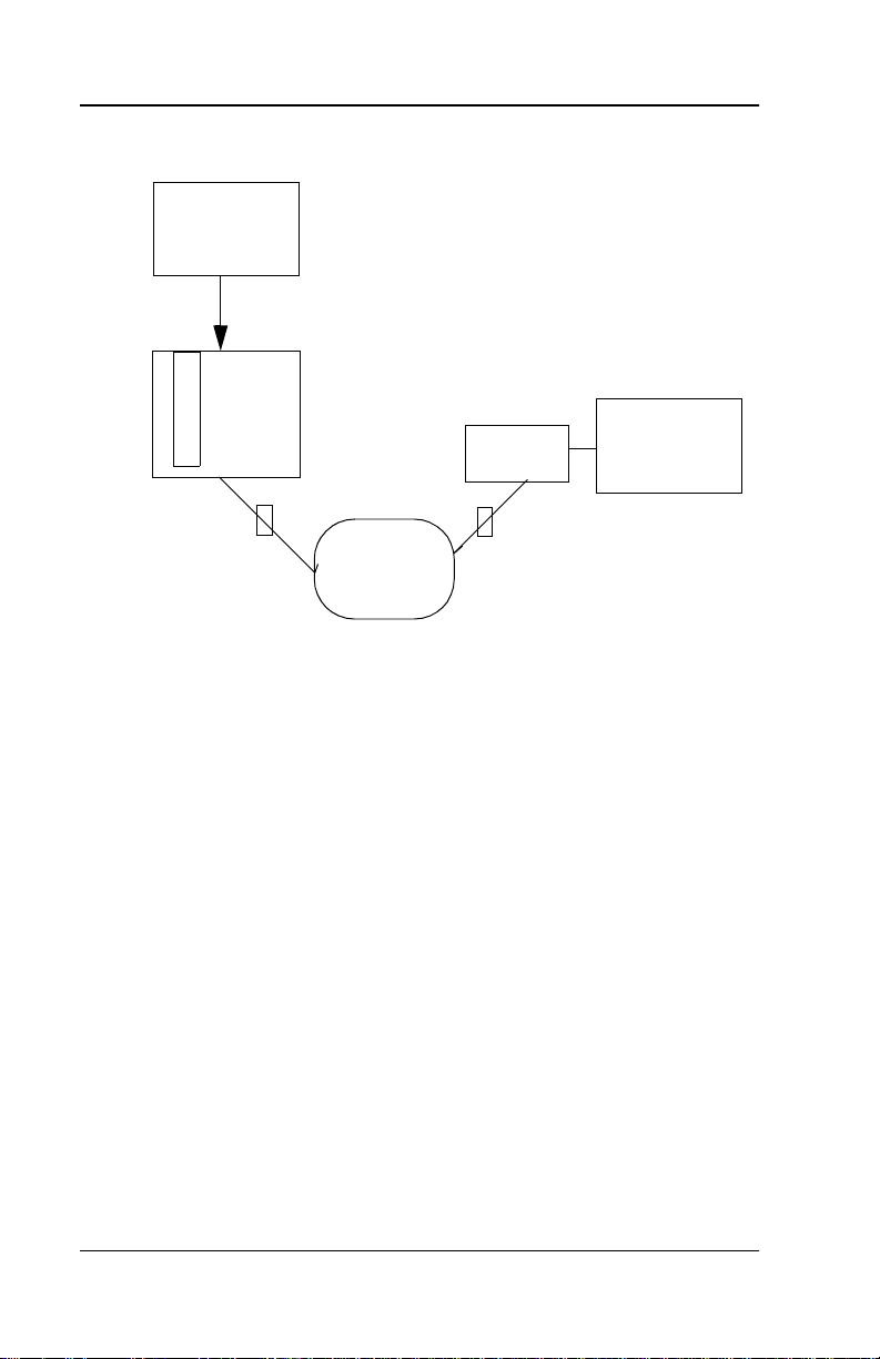
GENERAL DESCRIPTION
The ADTRAN T1 Data Service Unit (TSU), in either the standalone o r
the rackmount (RM) version for the Smart 1 6 shelf, provides a reliable,
high-speed data connection from customer synchronous data terminal equipment (DTE) through T1/FT1 lines.
The TSU serves as the link between user data sources such as LAN
bridges and routers, computers, CAD systems, and teleconferencing
equipment. The amount of bandwidth allocated to the port is userprogrammable at Nx56 or Nx64 kbps wher e N = 1 to 24. The DTE data
can occupy contiguous or alternate channels in the T1 stream and the
channels may start at any position. The DTE port provides a V.35 electrical and physical interface.
The network interface may be either D4 superframe format (SF) or extended superframe format (ESF) and the line code may be straight
B8ZS
or
of the T1 are filled with all
. In the case of a fractional connection, the unused channels
1s
idle code.
AMI
The TSU Network diagram is show n in Figure 1-1 on page 1-2.
61202077L1-20 TSU RM with V.35 User Manual 1-1
Page 16
Chapter 1. Introduction
Data
Terminal
Equipment
T
SMART 16
S
Shelf
U
R
M
TSU
Data
Terminal
Equipment
T1
T1
T1
Network
Figure 1-1. TSU Network Diagram
1-2 TSU RM with V.35 User Manual 61202077L1-20
Page 17

Chapter 2
The TSU RM consists of two cards. The first is the TSU main ca rd,
which has a front panel with nine LED indicators. The second card is
the TSU interface, which mounts on the r ear o f th e shelf and con t ains
all the jacks necessary for connection to the network, test jacks, and the
DTE connector.
Physical Description
FRONT PANEL
The front panel of the TSU contains nine LE D indica tors tha t provide
DTE interface, network, test, status and utility information. These indicators are shown in Figure 2-1.
Figure 2-1. TSU Front Panel
61202077L1-20 TSU RM with V.35 User Manual 2-1
Page 18

Chapter 2. Physical Description
OK Status (green)
OK LED
The
were passed, the LED is On.
indicates the result of the last self-test. If all the tests
DTE Status (green)
TD
Transmitted data from the DTE
RD
Received data from the TSU
RS
Request-to-send from the DTE
CS
Clear-to-send from the TSU
The active state for the status indicators (RS and CS ) is On,
while the on state for the data indicators (TD and RD)
represents a change in state from low to high.
Error/Alarm Status (red)
ERR
On
indicates that CRC errors (in ESF), bipolar violations (BPVs), or
frame bit errors have occurred within the last second.
ALM
On
indicates that one of the alarm conditions is currently active. See
Table 2-1 on page 2-3.
2-2 TSU RM with V.35 User Manual 61202077L1-20
Page 19

Chapter 2. Physical Description
Table 2-1. Alarm Conditions
ALARM DESCRIPTION
LOS Loss of signal at NI
AIS Alarm indicator signal (all 1s) received at NI
OOF Out of frame at NI
Yellow Yellow alarm received at NI
PLL
Alarm
Phase locked loop alarm (unable to lock on
clock source)
Loopback Status (yellow)
LB
LB LED
The
line loopback, payload loopback, or DTE loopback, the
indicates the loopback status of the unit. If the TSU is in
Dial Backup Status (yellow)
DBU
DBU ON
indicates the unit is in Dial Backup mode.
LB LED
is ON.
61202077L1-20 TSU RM with V.35 User Manual 2-3
Page 20
Chapter 2. Physical Description
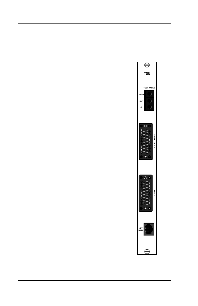
REAR PANEL
The TSU rear panel is shown in Figure 2-2. The connectors are shown
in Table 2-2 on page 2-5.
Figure 2-2. TSU Rear Panel
2-4 TSU RM with V.35 User Manual 61202077L1-20
Page 21

Chapter 2. Physical Description
Table 2-2. Rear Panel Connectors
Connectors Description
DTE V.35
NET RJ45
TEST jacks
MON jack
In and Out
jacks
This 34-pin connector provides the synchronous
DTE interface.
NET RJ45
The
connection to the T1/FT1 network
is made through the eight-pin modular jack. The
pin assignments for these connectors are
described in
Chapter 3, Installation
Network and DTE Connections
.
in
These three jacks are Bantam connectors that are
used when troubleshooting the T1 link.
The monitor jack is resistively isolated from the IN
jack and may be used during normal operation of
the T1 line.
IN
The
and
OUT
jacks are i ntrusive test jacks.
When a test connector is plugged into one of these
jacks, the corresponding connections on the
NET RJ45
The
jack are bypassed.
IN
jack is used to transmit data from a test set
into the TSU.
OUT
The
jack is used to transmit data out of the
TSU and into a test set
DBU V.35
This 34-pin connector provides the interface to an
external DTE device for use in a dial backup application.
61202077L1-20 TSU RM with V.35 User Manual 2-5
Page 22

Chapter 2. Physical Description
2-6 TSU RM with V.35 User Manual 61202077L1-20
Page 23

Chapter 3
Installation
UNPACKING
After unpacking the TSU, carefully inspect it for shipping damages. If
damage is suspected, immediately file a claim with the carrier and
contact ADTRAN Customer and Product Service ( see Customer Service
and Product Support on the inside back cover of this manual). If possible, keep the original shipping container to return the unit to
ADTRAN for repair or verification of shipping damage.
POWERING
The TSU receives power from the SMART 16 shelf. The shelf supplies
±5 VDC and ±12 VDC to the TSU when the unit is in one o f the 16 slots.
61202077L1-20 TSU RM with V.35 User Manual 3-1
Page 24

Chapter 3. Installation
NETWORK AND DTE CONNECTIONS
Network Connections
The eight-position modular jack labeled
TSU interface board is used for connection to the network. See Table
3-1 for the pinout of this connector.
Connector type = (USOC) RJ48C
Table 3-1. Network RJ45 Pinout
PIN NAME DESCRIPTION
1 R1 RX Data Ring
2 T1 RX Data Tip
3unused
4 R TX Data Ring
5 T TX Data Tip
6, 7, 8 unused
NET RJ45
on the rear of the
3-2 TSU RM with V.35 User Manual 61202077L1-20
Page 25

Chapter 3. Installation
DTE Connections
The two V.35 connectors located on the rear of the interface card are
used for connection to the primary DTE and to the external DTE DBU.
Connector type = V.35
Table 3-2. V.35 Pinout
PIN CCITT DESCRIPTION
A 101 Protective Ground (PG)
B 102 Signal Ground (SG)
C 105 Request-to-Send (RTS) from DTE
D 106 Clear-to-Send (CTS) to DTE
E 107 Data Set Ready (DSR) to DTE
F 109 Received Line Signal Detector (DCD) to DTE
J, L - Local Loopback (LL) from DTE
N, BB - Remote Loopback (RL) from DTE
R 104 Receive Data (RD-A) to DTE
T 104 Receive Data (RD-B) to DTE
V 115 RX Clock (RC-A) to DTE
X 115 RX Clock (RC-B) to DTE
P 103 Transmit Data (TD-A) from DTE
S 103 Transmit Data (TD-B) from DTE
Y 114 TX Clock (TC-A) to DTE
AA 114 TX Clock (TC-B) to DTE
U 113 External TX Clock (ETC-A) from DTE
W 113 External TX Clock (ETC-B) from DTE
K, NN - Test Mode (TM) to DTE
61202077L1-20 TSU RM with V.35 User Manual 3-3
Page 26

Chapter 3. Installation
3-4 TSU RM with V.35 User Manual 61202077L1-20
Page 27

Chapter 4
The user configures and controls the TSU through the controller card
in the SMART 16 shelf. The user has two choices of input/output devices for the controller card.
• An EIA-232 port, mounted on the rear of the shelf, provides a
VT 100 compatible ASCII terminal interface. A modem can be
used for remote applications.
• The ADTRAN DATAMATE, an optional hand-held control unit,
provides a 2x16-character LCD display and an 18-position keypad.
However, if the controller is a Smart16e, a 1 0BaseT interface is provided for Ethernet connection. In this way the unit may be configured and
controlled via a MIB browser, or via Advision.
Operation
61202077L1-20 TSU RM with V.35 User Manual 4-1
Page 28

Chapter 4. Operation
MENU STRUCTURE
The TSU uses a hierarchical structure to access its many features from
either the DATAMATE or terminal interface on the controller. All of
the setup features of the TSU are accessed by first making a choice
from the main menus shown in Figure 4-1 and Figure 4-2 and pressing
Enter.
TSU TERMINAL INTERFACE
1 STATUS
2 TESTS
3 CONFIG
4 UTIL
Figure 4-1. Display of Terminal Main Menu
1=STATUS 2=TEST
3=CONFIG 4=UTIL
Figure 4-2. Display of DATAMATE Main Menu
4-2 TSU RM with V.35 User Manual 61202077L1-20
Page 29

Chapter 4. Operation
CONFIGURATION MENU
The TSU has 8 network options and 11 DTE options. These options are
set from the terminal or
WORK
or
DTE
options under
DATAMATE
CONFIGURATION
interface by selecting the
.
NET-
From the main menu, select
3 and press Enter. The individual options
are described following the configuration menus shown in Figure 4-3,
below and Figure 4-4 on page 4-4.
TSU CONFIGURATION MENU
NETWORK OPTIONS
1 FORMAT=ESF
2 LINE CODE=B8ZS
3 YELLOW ALARM=ENABLED
4 XMIT PRM=OFF
5 CLOCK SOURCE=INTERNAL
6 BIT STUFFING=DISABLED
7 TX LB0=0.0 DB
8 RX SENSITIVITY=NORMAL
DTE/OTHER OPTIONS
9 RATE(NX56/64)=NX64
10 CONT/ALT CHANNELS=CONTIGUOUS
11 DTE TX CLK=INTRNAL
12 STARTING CHANNEL=1
13 NUMBER OF CHANNELS=24
14 DATA OPTION=NORMAL
15 CTS OPTION= NORMAL
16 DCD OPTION=NORMAL
17 DSR OPTION= NORMAL
18 INBAND OPTION=OFF
19 DBU OPTIONS
Figure 4-3. Display of Terminal Configuration Menu
61202077L1-20 TSU RM with V.35 User Manual 4-3
Page 30

Chapter 4. Operation
1) FORMAT
2) LINE CODE
3) YEL. ALARM
1)NETWORK OPT IO N S 4) XMIT PRM
5) CLOCK SOURCE
6) BIT STUFFING
7) SET LBO
8) RX SENSITIVITY
CONFIG 1) RATE (Nx56/64)
2) CONT/ALT CHAN
3) DTE TX CLK
4) START CHANNEL
2) DTE OPTIONS 5) # OF CHANNELS
6) DATA OPTION
7) CTS OPTION
8) DCD OPTION 1) BACKUP MODE
9) DSR OPTION 2) BACKUP ON
A) INBAND OPTION 3) PATTERN VERIFY
3) DBU OPTIONS 5) ENABLE HR
4) WKEND LOCKOUT
6) DISABLE HR
7) BACKUP DELAY
8) RESTORE DLY
9) RETRY DLY
A) NUM RETRIES
Figure 4-4. DATAMATE Configuration Menu Tree
4-4 TSU RM with V.35 User Manual 61202077L1-20
Page 31

Chapter 4. Operation
Network Options
Format
This option selects the framing format for the network interface. Superframe format (SF) and extended superframe format (ESF) are the
two choices. ESF provides an out-of-band communications channel
that allows the carrier to retrieve performance monitoring data and
initiate loopbacks in accordance with ANSI T1.403 and AT&T 54016.
If on a public network, this setting must be in accordance with the type
of service provided by the carrier.
Line Code
This option selects whether the TSU uses straight AMI line coding or
B8ZS. B8ZS ensures
placing an all
0s
-density requirements on the network by re-
1s
byte with a specific byte containing two intentional
bipolar violations (BPVs). If on a public network, this setting must be
in accordance with the service provided by the carrier.
Yellow Alarm
This option enables or disables the transmission of yellow alarms by
the TSU. When the TSU is in red alarm caused by loss of signal/out
of frame conditions (LOS/OOF), a pattern may be sent towards the
network to alert the carrier/far end of the red alarm. In D4 format, the
yellow alarm is sent in-band and thus corrupts the data in the outgoing direction. Some private network applications may require that the
yellow alarm transmission be disabled. If using a carrier-provided T1,
enable the yellow alarm.
Transmit Performance Report Message (XMIT PRM)
When this option is enabled, a status update (Performance Report
Message) is sent towards the network by the TSU when in ESF m ode.
This report is sent in accordance with ANSI T1.403 and is a summary
of the last four seconds of operation. Enable this option unless told
otherwise by the carrier. The PRM is sent when this option is
61202077L1-20 TSU RM with V.35 User Manual 4-5
ON
.
Page 32

Chapter 4. Operation
Clock Source
A master timing source must be defined for proper operation of the T1
link. If the TSU is connected to a carrier-provided T1 line, the clock
source should be set to
work, the user must option one of the TSUs for
the other to internal or
TIMING
, the TSU uses its internal 1.544 MHz clock source. When op-
NETWORK
DTE TIMING
. If the TSU is part of a private net-
NETWORK TIMING
. When optioned for
INTERNAL
and
tioned for DTE, the TSU derives timing from the DTE transmit clock.
Bit Stuffing
Bit stuffing is an option used to ensure pulse density requirements on
carrier-provided T1 lines in accordance with ANSI T1. 403 and AT&T
62411. If B8ZS is e nabled, Nx56 is optioned, alternat e channels are being used, or inverted data (HDLC) is used, the N pulse density requirement is already met and bit stuffing should be disabled. If none
of the above options are selected, enable bit stuffing.
Bit stuffing corrupts the user data from the DTE when it fails
to meet the 12.5 perce n t 1s de n sity re qu ireme n t. If the DTE
data do not meet this requ irement , enab le one o f the ab ove options.
Set Line Build Out
Set Line Build Out (Set LBO) selects the transmit level of the outgoing
T1 stream. Attenuation of the T1 signal can be added to avoid overdriving repeaters on the T1 line. On most carrier-provided T1 lines, a
smart jack is installed at the network demarcation point and should
receive a
signal. If there is no smart jack, the auto line build-out
0 dB
feature may be deployed. This feature enables the TSU to base its
transmit level on the level of the signal received from the network. If
trouble exists with the auto line build-out feature, try each of the selections until achieving reliable operation.
4-6 TSU RM with V.35 User Manual 61202077L1-20
Page 33

Chapter 4. Operation
RX Sensitivity
This option selects the desired receiver sensitivity setting. The factory
default is
EXTENDED
NORMAL
NORMAL
, which is adequate for most applications. The
setting should be used only in applications where the
setting will not suffice.
DTE/Other Options
Rate (Nx56/64)
This selection chooses whether the DTE data rate is Nx56 or Nx64
kbps, where N = 1 to 24. N corresponds to the number of channels occupied within the T1/FT1 stream.
On Fractional T1 (FT1), the user is billed based on bandwidth (number
of channels allocated) so N determines the cost of a circuit. On a private network, the li miti ng f actor fo r N wi ll be the max imum da ta ra te
of the DTE equipment.
On a carrier-provided T1 that does not support B8ZS, Nx56 may be
chosen to ensure pulse density requirements and eliminate 1s density
restrictions on the DTE data. The trade -off is a 1/8 red uction in bandwidth.
The alternate channels option discussed below may also be used to
meet this requirement; however, the carrier must allow it. The maximum number of channels is 12.
Contiguous/Alternate Channels
As mentioned above, the TSU may be optioned to use contiguous or
alternate channels within the T1 stream. The
AL TERNATE CHANNELS
option provides another means of meeting pulse density requirements. If the number of channels is no more than 12 and the carrier
allows this setting, this option may be the better solution.
The
ALTERNATE CHANNELS
option means that every other channel
within the T1 (from the starting channel position through the ending
channel position) is occupied with DTE data. All other channels wi ll
have idle code.
61202077L1-20 TSU RM with V.35 User Manual 4-7
Page 34

Chapter 4. Operation
The
Contiguous Channels
option means that the DTE data occupy one
channel after the other (starting at the programmed channel and using
the number of channels chosen).
DTE Transmit (Tx) Clock
This option controls the clock the TSU uses to accept the transmit (TX)
data from the DTE. Most applications will allow for this to be set to
INTERNAL
data), you can select the clock as
. If the interface cable is long (causing a phase shift in the
INT/INV
(Internal/Inverted). This
switches the phase of the clock, which should compensate for a long
cable. The factory default setting for this option is
AUTO DTE TX CLK
The
setting will allow the TSU to autom atically
AUTO
.
detect the delay from the DTE device to the TSU and set the proper
phase of the clock. This feature will automatically select between the
INTERNAL
data, the clock selection is set to
and
INT-INV
settings. If the DTE provides a clock with TX
EXTERNAL
. The TSU will depend on
an externally supplied clock to accept the TX data.
Starting Channel
The DTE data can occupy the T1 stream starting in a ny of the 24 channels. For a full T1 link, this value should be one. For a public FT1 link,
this value should correspond to the value specified by the carrier.
Number of Channels (N)
The number of channels used within the T1 stream can be set from 1
to 24. The user bandwidth and D TE data rate a re determined by Nx56
kbps or Nx64 kbps, depending upon the rate setting described in
Rate (Nx56/64) on page 4-7.
Data Option
The data option may be set for
NORMAL
INVERT
or
. The
INVERT
mode provides another method to meet pulse density requirements.
INVERT
In the
mode, data transmitted to or received from the DTE are
inverted before being sent downstream. This option is useful for
HDLC-style DTE protocols since they restrict the number of consecu-
4-8 TSU RM with V.35 User Manual 61202077L1-20
Page 35

Chapter 4. Operation
tive 1s transmitted. Inverting HDLC data restricts the number of consecutive zeros transmitted. The data are sent unaltered in the
NORMAL
mode.
CTS Option
This option allows Clear To Send (CTS) to operate no rmally (Normal)
or to be forced
all the time (Forced On). This option should be set
ON
in accordance with the DTE requirements. Normal operation is described below.
CTS usually follows RTS. CTS is
ditions exist
:
OFF
when any of the following con-
• RTS is not asserted
• TSU is in self-test mode
• TSU is in local loopback
• TSU is sending test pattern
• TSU is receiving yellow alarm in ESF mode.
DCD Option
This option allows
NORMAL
(
) or to be forced
Data Carrier Detect
all the time (
ON
(DCD) to operate normally
FORCED ON
). This option
should be set in accordance with the DTE requirements. Normal operation is described below.
DCD, also known as Received Line Signal Detector (RLSD), is ON
when data are being received from the network. DCD is
OFF
when
either of the following conditions exist:
• Network signal is out-of-frame
• TSU is sending a test pattern.
61202077L1-20 TSU RM with V.35 User Manual 4-9
Page 36

Chapter 4. Operation
DSR Option
This option allows
NORMAL
(
) or to be forced ON all the time (Forced On). This option
Data Set Ready
(DSR) to operate normally
should be set in accordance with the DTE requirements. Normal operation is described below.
DSR is OFF if any of the following conditions exist:
• TSU is in self-test mode.
• TSU is in local loopback mode
• TSU is sending test pattern.
Inband Option
The Inband Configuration Channel ena bles/disables an 8 kbps remote configuration channel. When this option is set to ON, the first
occupied DS0 operates in 56K mode and the DTE clock rate is reduced
by 8 kbps. The TSU uses this 8 kbps channel to send and receive configuration data across a T1 span. This feature is useful when FDL connectivity is not available across the T1 span.
The 8 kbps channel is onl y ta ken o ut of t he first DS0. If t wo 64K D S0s
are mapped, the DTE rate would be 120 kbps instead of 128 kbps. This
menu option can also be set to
AUTO
, which activates the Inband
Channel only when commands are sent from T-Watch to the remote
unit. If no T-Watch activity is detected for 10 minutes, the Inband
Channel is deactivated.
DBU Options
Backup Mode
Configures the TSU to originate or to answer a dial backup
call. You can completely disable dial backup either by select-
DISABLE
ing
BACKUP DELAY
4-10 TSU RM with V.35 User Manual 61202077L1-20
or by setting the backup delay to
on page 4-11 for details.
NEVER
. See
Page 37

Chapter 4. Operation
Backup On
Sets the dial backup criteria.
NETWORK FAIL
uses conditions
such as Red Alarm, Yellow Alarm, and Inband Poll Failure as
dial backup criteria.
NET/DA TA FAIL
uses a data transition
failure in addition to all of the network fail conditio ns as criteria for dial backup.
Pattern Verify
Establishes the integrity of the dial backup link. When enabled, the DTE DBU generates an alternating ones pattern
which can be detected by the far end unit. Once the pattern is
detected, backup of the primary network will continue. For
proper operation, this option must be enabled on both ends of
the dial backup link.
Wkend Lockout
If enabled, no backup will occur from midnight Friday to midnight Sunday.
Enable HR
Sets the beginning of the dial backup window. Dial backup is
only allowed between the enable and disable hours. If the enable and disable hours are set to zero, dial backup will be allowed 24 hours a day.
Disable HR
Sets the end of the dial backup window.
Backup Delay
Sets the delay time between the occurrence of a backup condition and the initiation of a dial backup session. Delay times
include: 1 sec, 3 sec, 10 sec, 30 sec, 1 min, 5 min, 10 min, Never.
If
NEVER
is selected, the TSU will not go into dial backup
mode when a backup condition is present. This is equivalent
to disabling the dial backup feature under the
BACKUP MODE
menu.
61202077L1-20 TSU RM with V.35 User Manual 4-11
Page 38

Chapter 4. Operation
Restore Dly
Sets the delay time for switching back to the T1/FT1 network
after no backup conditions exist. Delay times include: 1 sec,
3 sec, 10 sec, 30 sec, 1 min, 5 min, 10 min, Never.
If
NEVER
is selected, the TSU stays in dial backup even after
no backup conditions exist on the primary ne twork. To
switch back to the primary network, select
from the
DBU UTILITIES
menu.
FORCED RESTORE
Retry Dly
Sets the delay time between dial backup retries. Delay times
include: 1 sec, 3 sec, 10 sec, 30 sec, 1 min, 5 min, 10 min, Never.
Setting the delay to
NEVER
is the same as setting the number
of retries to zero.
Num Retries
Sets the number of dial backup retries. Valid range is 1-99.
4-12 TSU RM with V.35 User Manual 61202077L1-20
Page 39

Chapter 4. Operation
TEST MENU
The test menus initiate different types of tests and allow the user to
view test results. The test menu can be accessed by selecting 2 from
either the terminal or the
Figure 4-5 through Figure 4-8 followed by a di scussion of each test
item.
LOCAL TESTS
1 RUN SELF TEST
2 LOCAL LBS=NO LOOPBACK
3 REMOTE LBS=NO LOOPBACK
DATAMATE
TSU TEST OPTIONS
. The test menus are shown in
REMOTE TESTS
4) TEST PATTERN=NO PATTERN
5) DBU LOOPBACK=DISABLE
6) INTERFACE TEST=ENABLE
Figure 4-5. Display of Terminal Test Menu
TSU TEST RESULTS
PATTERN (511) ERRORS = 102
1 EXIT TEST
2 CLEAR ERRORS
Figure 4-6. Display of Terminal Test Results
61202077L1-20 TSU RM with V.35 User Manual 4-13
Page 40

Chapter 4. Operation
1) RUN SELF TEST 1) NO LOOPBACK
1) LOCAL UNIT 2) LOCAL LBS 2) PAYLOAD ON
3) LINE ON
TEST 4) DTE LB ON
5) DATA LB ON
1) TEST RESULTS 1) NO PA TTERN
2) REMOTE UNIT 2) TEST PATTERN 2) ALL ONES
3) ALL ZEROS
4) 511
5) 1 IN 8
6) QRSS
1) NO LOOPBACK
3) REMOTE LBS 2) AT&T FDL PLB
3) ANSI FDL PLB
4) AT&T INBAND LLB
1) DBU LOOPBACK 5) ANSI FDL LLB
3) DBU TESTS 2) INTERFACE TST 6) FT1 LOOPBACK
3) DBU TST RESULT
Figure 4-7. DATAMATE Test Menu Tree
CODE VIOL TOTAL
0
Figure 4-8. DATAMATE Test Results Display Example
4-14 TSU RM with V.35 User Manual 61202077L1-20
Page 41

Chapter 4. Operation
Local Unit
Run Self-Test
The TSU has an extensive set of self-test functions. When this test is
initiated from the terminal, the TSU branches to the status display
where the self-test results are shown. When this test is initiated from
DAT AMATE
the
self-test result. The LEDs on the front of the TSU scroll during self test.
Local Loopbacks
When the TSU is performing a local loopback, it loops the data received at one of its interfaces back to transmit data for that interface.
When in line loopback, every bit received at the network interface is
looped back to the network as shown in Figure 4-9.
, the firmware checksum is displayed, followed by the
Figure 4-9. Local Line Loopback
For payload loopback, the TSU loops back all the data (payload) bits
within the T1 stream, but regenerates the framing bits as shown in
Figure 4-10.
61202077L1-20 TSU RM with V.35 User Manual 4-15
Page 42

Chapter 4. Operation
Figure 4-10. Payload Loopback
When in DTE loopback, the TSU loops all the data received at the DTE
interface back to the DTE as shown in Figure 4-11.
Figure 4-11. Local DTE Loopback
4-16 TSU RM with V.35 User Manual 61202077L1-20
Page 43

Chapter 4. Operation
Figure 4-12. Data Loopback
When in data loopback the TSU loops back all active channels toward
the network. Data passes through the line interface, framing device,
and FIFOs of the DTE interface. All ones are inserted into the idle
channels.
Remote Unit
Remote Loopbacks
When a remote loopback is chosen, a code is sent towards the network
that is intended to loopback the far end TSU. These loopbacks will be
either line (LLB) or payload (PLB) as described in
on page 4-15. Some of these codes are sent out-of-band in the ESF Facility Data Link (FDL - 4 kbps control channel) and some a re se nt inband. The FDL codes only work when the framing bits are actually
transported from one end of the T1 to the other. This type of test is valid for full T1 but may not be for FT1. The AT&T inband LLB and the
V.54 inband PLB do not use the FDL, but the AT&T cod e requires a full
T1 link. For FT1, it is more reliable to use the V.54 INBAND PLB when
the units on both ends support it.
61202077L1-20 TSU RM with V.35 User Manual 4-17
LOCAL LOOPBACKS
Page 44

Chapter 4. Operation
Test Patterns
The TSU can send five different data patterns to the network. These
patterns are used for testing the T1 link. The all 1’s pattern sends all
1s in every channel of the T1. The all 0’s pattern sends all zeros in every channel of the T1. The 1 in 8 pattern sends a fixed pattern where
one out of every eight bits is set. This pattern is used to test pulse density requirements, and also occupies all channels of the T1. The 511
and QRSS patterns are pseudo-random patterns sent only in the active
DS0s.
When a pattern is started from the terminal, a
TSU REST RESULTS
screen is displayed. If the 511 or QRSS pattern is sent, a count of receive errors is displayed. If any other pattern is sent, a Code Violations
(CV) total is displayed. If the pattern is started from the DATAMATE,
the Error or CV total is found under the
TEST RESULTS
selection.
The Error and CV Totals are cleared upon entering the display.
DBU Tests
DBU Loopback
When enabled, this option loops the DBU’s receive to its transmit.
Dial backup data is looped back towards the network.
Interface Test
Tests the integrity of the dial backup interface by forcing a dial backup
session and then sending an alternating pattern. In order to test both
the transmit and receive sides of the interface, the remote DBU must
be placed in loopback (TX and RX tied together). Display the test results with the
DBU TEST RESULT
option.
DBU Test Result
This is used in conjunction with th e interface test to display the DBU
test results. If the alternating pattern is being successfully received
across the dial backup link, the DBU error total will read
.
0
4-18 TSU RM with V.35 User Manual 61202077L1-20
Page 45

Chapter 4. Operation
STATUS MENU
The status menus of the DATAMATE and terminal allow errors and
alarms to be viewed and error/alarm histories to be cleared. If an
alarm occurs after power-up or after the history registers were last
cleared, the history registers are set again. Current errors/alarms reflect only the current status. The different errors and alarms were discussed in the Front Panel section of Chapter 2. The terminal Status
menus and the DATAMATE Status tree are shown in Figure 4-13
through Figure 4-17.
TSU STATUS
1 CLEAR HISTORY
2 DISPLAY STATUS
3 LOCAL PERFORMANCE
4 REMOTE PERFORMANCE
5) DBU STATUS
Figure 4-13. Display of Terminal Status Selection Menu
61202077L1-20 TSU RM with V.35 User Manual 4-19
Page 46

Chapter 4. Operation
TSU STATUS DISPLAY
CURRENT ERRORS/ALARMS/RESULTS
RX LOS= YES
RX AIS= NO
RX OOF = YES
RX YELLOW = NO
RX RED= YES
RX CVS = NO
RX BPVS = NO
RX FRM ERRS = NO
PLL ALARM = NO
SELF TEST = PASS
SOFTWARE REV = REVISION E
CHECKSUM = E203
Figure 4-14. Terminal Status Display Example
DBU STATUS
DCD=NO
DTR=NO
DSR=NO
RTS=NO
CTS=NO
RI=NO
HISTORY ERRORS/ALARMS
RX LOS = YES
RX ASI = YES
RX OOF= YES
RX YELLOW = YES
RX RED= YES
RX CVS = YES
RX BPVS = YES
RX FRM ERRS = YES
PLL ALARM = YES
DBU SECONDS=0
IN DBU=NO
Figure 4-15. Display of Terminal DBU Status
4-20 TSU RM with V.35 User Manual 61202077L1-20
Page 47

Chapter 4. Operation
RX LOS
RX ALS
RX OOF
RX YELLOW
RX RED
RX CVS
1) CLEAR HISTORY RX BPVS
2) CURR ERR/ALM RX FRM ERRS
3) ERR/ALM HIST PLL ALARM
STATUS 4) RESET LOC PERF DCD
5) VIEW LOC PERF ES DTR
6) RESET REM PERF SES DSR
7) VIEW REM PERF UAS RTS
%AV CTS
%EF RI
8) DBU STATUS DBU SECS
IN DBU
Figure 4-16. DATAMATE Status Menu Tree
(*YES, -NO)
NI RX AIS
*
Figure 4-17. DATAMATE Status Display Example
61202077L1-20 TSU RM with V.35 User Manual 4-21
Page 48

Chapter 4. Operation
Status Display Explanation
Status Displays
• NI means
•TI means
DATAMATE Status
• The first line indicates that an asterisk
(-)
means No.
• The second line lists the applicable interface alarm in question.
• The last field shows the state of
Performance monitoring statistics for either the local or remote TSU
can be viewed on the DATAMATE or displayed on a CRT screen
through the terminal interface for the SMART16 shelf.
The parameters available in the perfomance monitoring reports are:
Network Interface
Terminal
DTE Interface
or
(*)
means
error/alarm
Yes
and a dash
.
%AV
%EF
ES
UAS
SES
BES
LOFC
percent available seconds
percent error-free seconds
errored seconds
unavailable seconds
severely errored seconds
bursty errored seconds
loss of frame count
With the DATAMATE, statistics for the local TSU are viewed by selecting
VIEW LOC PERF
in the
Status
menu (shown in Figure 4-16 on
page 4-21). Statistics for the remote TSU are viewed by selecting
VIEW REM PERF
from this menu. A sample DATAMATE perfor-
mance monitoring display is shown in Figure 4-18 on page 4-24.
The performance parameter plus the 15-minute and 24-hour totals for
the selected parameter are shown on the second line of the display under their respective legends.
4-22 TSU RM with V.35 User Manual 61202077L1-20
Page 49

Chapter 4. Operation
Other performance parameters are displayed by using the arrow keys
to cycle the display through the complete list of the available parameters.
The statistics for the local TSU can be cleared by selecting
LOC PERF
from the menu shown in Figure 4-16 on page 4-21.
The statistics for the remote TSU can be cleared by selecting
REM PERF
from this menu.
RESET
RESET
For the terminal interface, the performance monitoring menu for the
local TSU is displayed by selecting
Status
menu shown in Figure 4-13 on page 4-19, while the perfor-
LOCAL PERFORMANCE
in the
mance monitoring menu for the remote TSU is accessed by selecting
REMOTE PERFORMANCE
from the menu.
The performance monitoring menu for the local TS U is shown in Figure 4-19 on page 4-24. The only difference between this menu and the
menu for the remote TSU is the first line of the display, which denotes
remote performance monitoring instead of local performance monitoring.
Both a performance summary and detailed report are available with
the terminal interface. The performance summary report shows statistics for the current 15-minute interval, the 24-hour totals, the number of valid 15-minute intervals, and the seconds into the current
15-minute interval.
A performance summary report is shown in Figure 4-20 on page 4-24.
The detailed report provides a 24-hour history of any one of the available parameters. One hour totals for the last 24-hours are displayed
for the selected parameter as shown in Figure 4-21 on page 4-25.
The remote performance statistics are available only when
the network interface framing format is optioned for ESF.
61202077L1-20 TSU RM with V.35 User Manual 4-23
Page 50

Chapter 4. Operation
ES 15/24 HR
10/20
Figure 4-18. DATAMATE Performance Monitoring Display
TSU LOCAL PERFORMANCE MONITORING
1 CLR LOCAL PERF
2 PERFORMANCE SUMMARY
3 24 HOUR ES REPORT
4 24 HOUR UAS REPORT
5 24 HOUR SES REPORT
6 24 HOUR BES REPORT
7 24 HOUR LOFC REPORT
Figure 4-19. Terminal Performance Monitoring Selection
VALID INTERNALS = 21
CURRENT SECONDS = 334
CURRENT %AV = 0.3
%EF = 0.3
ES = 0
UAS = 333
SES = 0
BES = 0
LOFC = 0
24 HOUR %AV = 60.7
%EF = 40.5
ES = 42
WAS =7426
SES = 39
BES = 3
LOFC = 2
TSU LOCAL PERFORMANCE SUMMARY
Figure 4-20. Terminal Performance Summary
4-24 TSU RM with V.35 User Manual 61202077L1-20
Page 51

INTERVAL (HR)
1
2
3
4
5
6
7
8
9
10
11
12
Chapter 4. Operation
TSU LOCAL ES
TOTAL
0
0
10
32
0
0
0
0
0
0
0
0
INTERVAL (HR)
13
14
15
16
17
18
19
20
21
22
23
24
TOTAL
0
0
0
0
0
0
0
0
0
0
0
0
Figure 4-21. Terminal Detailed Report Example
61202077L1-20 TSU RM with V.35 User Manual 4-25
Page 52

Chapter 4. Operation
UTILITY MENU
The Utility menu displays and sets system parameters (see Figure 4-
23). This includes setting the time and date, and resetting all parameters to factory values and forced DBU options. This menu also displays the unit’s software revision and checksum. The Terminal Utility
Menu and the DATAMATE status tre e are sho wn i n Figu re 4- 22 a nd
Figure 4-23.
TSU UTILITIES
1) FACTORY RESTORE
2) DIAL BACKUP=FORCED RESTORE
3) TIME/DATE
Figure 4-22. Terminal Utility Menu Tree
1)FACT RESTORE
2) SOFTWARE REV 1) DISPLAY TIME/DATE
3) TIME/DATE 2) SET TIME 1) SET HOUR
UTIL 2) SET MIN
3) SET DATE 1)SET MONTH
2) SET DATE
3) SET YEAR
4) DIAL BACKUP 1) FORCE DBU
2) FORCED RESTORE
Figure 4-23. DATAMATE Utility Menu Tree
4-26 TSU RM with V.35 User Manual 61202077L1-20
Page 53

Factory Restore
Chapter 4. Operation
Fact Restore
resets all the configuration options to factory preset val-
ues. These values are listed in Table 4-1 and Table 4-2.
Table 4-1. Network Factory Defaults
OPTION SETTING
FORMAT ESF
LINE CODE B8ZS
YELLOW ALARM ENABLED
XMIT PRM OFF
CLOCK SOURCE NETWORK
BIT STUFFING DISABLED
TX LBO 0.0 dB
RX SENSITIVITY NORMAL
Table 4-2. DTE Factory Defaults
OPTION SETTING
RATE (NX56/64) Nx64
CONT/ALT CHANNELS CONTIGUOUS
DTE TX CLK INTERNAL
STARTING CHANNEL 1
NUMBER OF CHANNELS 24
DATA OPTION NORMAL
CTS OPTION NORMAL
DCD OPTION NORMAL
DSR OPTION NORMAL
INBAND OPTION OFF
61202077L1-20 TSU RM with V.35 User Manual 4-27
Page 54

Chapter 4. Operation
Software Rev
Use the Software Revision submenu to access the display of the current software revision level and its checksum. This information is required when requesting assistance from ADTRAN Customer and
Products Service or when updates are needed.
Time/Date
This menu option is used to view or to edit the current time and date.
The time and date are maintained during power off conditions.
From Datamate
To display the current time and date:
1. Select
2. To edit time and date, select
3. Enter the desired minute, hour, month, date, or year and press
From Terminal
To display and edit the current time and date:
1. Select
2. Select either the time or date and press
3. Enter the desired hour, minute, month, date, or year and press
DISPLAY TIME/DATE
Enter.
TIME/DATE
Enter.
.
SET TIME
from the Utilities menu.
or
Enter.
SET DATE
.
4-28 TSU RM with V.35 User Manual 61202077L1-20
Page 55

Chapter 4. Operation
Dial Backup (DBU) Utilities
Use the dial backup utilities menu to force a dial backup call or hang
up a dial backup call.
Force DBU
Choosing this option causes the unit to initiate a dial backup call.
BACKUP MODE
must be set to
will be terminated after the amount of time specified in
DELAY
has elapsed.
Forced Restore
Select this option to drop the DBU call and restore the T1/FT1 link.
ORIGINATE
and the dial backup call
RESTORE
61202077L1-20 TSU RM with V.35 User Manual 4-29
Page 56

Chapter 4. Operation
4-30 TSU RM with V.35 User Manual 61202077L1-20
Page 57

Appendix A
Specifications
Network Interface
Framing Format
Line Code
TX LBO
Performance
Monitoring
DTE Interface
DTE Data Rates
Channel Allocation
Starting Channel
Timing Sources
Data Option
DS1 interface per AT&T 62411 and ANSI
T1.403
D4 (SF) or ESF
AMI or B8ZS
Auto or Manual from 0.0 dB to -22.5 dB
As per ANSI T1.403 and AT&T 54016
V.35 synchronous
Nx56 or Nx64 kbps (N = 1 to 24)
Alternate or Contiguous
Programmable
Network, Internal, or DTE master
Normal or Inverted data (Inverted HDLC)
61202077L1-20 TSU RM with V.35 User Manual A-1
Page 58

Appendix A. Specifications
A-2 TSU RM with V.35 User Manual 61202077L1-20
Page 59

Index
A
ADTRAN T1 Data Service Unit,
description
ADTRAN Web Site
ADTRAN Year 2000 (Y2K) Readiness Disclosure
alarm conditions
1-1
iii
iii
2-3
B
backup delay 4-11
4-11
4-6
4-10
Backup Mode
Backup On
bit stuffing
C
Canadian equipment limitations
vi
4-6
4-9
2-5
viii
A-1
4-3
4-
channel allocation
clock source
configuration men u
connector, V.35
contiguous/alternate channels
7
CTS option
Customer Service
D
Data Option 4-8
data option
DBU Loopback
DBU Options
DBU Test Result
DBU Tests
DBU V.35, on rear panel
DCD option
Dial Backup (DBU) Utilities
Disable HR
display and edit the current time
4-18
A-1
4-10
4-9
4-11
4-18
4-18
2-5
4-29
3-3
4-28
4-7
4-27
4-28
4-8
2-2
2-
and date, from terminal
display the current time and date,
from DATAMATE
DSR option
DTE connections
DTE data rates
DTE factory defaults
DTE interface
DTE Status, TD, RD, RS, CS
DTE Transmit (Tx) Clock
DTE V.35, rear panel connector
5
DTE/other options
4-10
A-1
A-1
E
EIA-232 port, on rear smart 16
shelf
4-1
4-11
iii
E-mail, for Y2K
Enable HR
ESF
A-1
F
factory defaults, DTE 4-27
4-5
2-1
4-27
iii
4-5
factory defaults, network
4-29
4-27
4-29
A-1
iv
Factory Restore
Faxback Document Line, Y2K
FCC regulations
Force DBU
Forced Restore
Format, for network interface
Format, network option
framing format
front panel, description
G
General Description 1-1
I
IN and OUT jacks, on rear panel
61202077L1-20 TSU RM with V.35 User Manual Index-1
Page 60

Index
2-5
A-1
3-1
4-18
4-10
Inband Option
Installation
Interface Test
internal
L
line code A-1
line code, network option
4-15
4-15
local loopbacks
Local Unit
Loopback Status, LB, DBU
4-5
2-3
M
MON, monitor jack, on rear panel
2-5
N
NET RJ45
pinout
NET RJ45, rear connector
network connections
network diagram
network factory defaults
network interface
normal
number of channels (N)
A-1
3-2
1-2
A-1
3-2
4-8
2-5
4-27
O
OK LED, with self-test 2-2
Operation
4-1
P
Pattern Verify 4-11
payload loopback
Performance Monitoring
performance monitoring
Physical Description
powering, from SMART 16 shelf
3-1
Powering, Smart16 shelf
Product Matrix, Y2K informa tion
iii
4-16
2-1
3-1
A-1
A-1
R
radio frequency interference
2-4
4-17
4-15
4-7
v
4-17
2-5
4-7
statement, FCC
rate (Nx56/64), DTE option
rear panel
rear panel connectors
remote loopbacks
remote unit
run self test
RX Sensitivity
S
safety instructions vii
A-1
4-19
4-6
1-1
4-8, A-1
3-1
4-
set line build out
SF
A-1
SMART 16 shelf
SMART 16, power up
Software Rev, utility su bmenu
28
Specifications
starting channel
Status Menu
T
test jacks, rear panel 2-5
4-5
A-1
4-13
4-18
A-1
4-28
1-2
Test Menu
test patterns
Time/Date display
timing sources
transmit performance report message
TSU Network Diagram
Tx LBO
U
unpacking, instructions 3-1
V
V.35 pinout 3-3
W
Warranty and Customer Service
viii
Wkend Lockout
4-11
61202077L1-20 TSU RM with V.35 User Manual Index-2
Page 61

Index
X
XMIT PRM 4-5
Y
Y2K Project Line iii
Y2K readiness disclosure
Y2K, Faxback Document Line
yellow alarm
4-5
iii
iii
61202077L1-20 TSU RM with V.35 User Manual Index-3
Page 62

Index
61202077L1-20 TSU RM with V.35 User Manual Index-4
Page 63

Product Support Information
Presales Inquiries and Applications Support
Please contact your local distributor, ADTRAN Applications Engineering, or ADTRAN Sales:
Applications Engineering (800) 615-1176
Sales (800) 827-0807
Post-Sales Support
Please contact your local distributor first. If your local distributor cannot help, please contact ADTRAN Technical Support and have the
unit serial number available.
Technical Support (888) 4ADTRAN
Repair and Return
If ADTRAN Technical Support determines that a repair is needed,
Technical Support will coordinate with theCustomer and Product Service (CAPS) department to issue an RMA number. For information
regarding equipment currently in house or possible fees associated
with repair, contact CAPS directly at the following number:
CAPS Department (256) 963-8722
Identify the RMA number clearly on the package (below address), and
return to the following address:
ADTRAN, Inc.
CAPS Department
6767 Old Madison Pike
Progress Center
Building #6, Suite 690
Huntsville, AL 35807
RMA # _____________
Page 64

 Loading...