

Page 1
TRDDS-R
Total Reach® All Rate DDS Termination Unit
For Outside Plant and Customer Premise
Installation and Maintenance
CONTENTS
1. GENERAL........................................................................... 1
2. OPTIONS ............................................................................ 2
3. INSTALLATION ................................................................ 2
4. TESTING............................................................................. 4
5. DEPLOYMENT GUIDELINES ......................................... 6
6. WARRANTY AND CUSTOMER SERVICE ................... 7
FIGURES
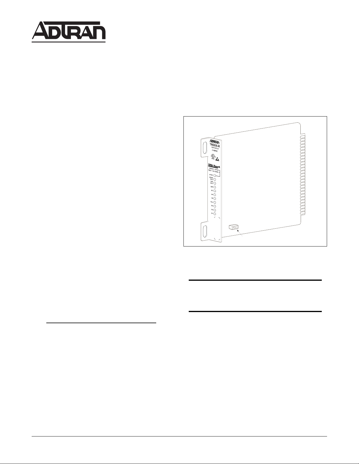
Figure 1. ADTRAN TRDDS-R ............................................. 1
Figure 2. Total Reach DDS Circuit Diagram ........................ 2
Figure 3. TRDDS-R Option Switch....................................... 2
Figure 4. Circuit Card Pin Assignments ................................ 3
Figure 5. Signal Loss Indication ............................................ 4
Figure 6. Total Reach Dataport Bidirectional Loopback
Pass-Thru Mode...................................................... 6
Figure 7. Total Reach Dataport Bidirectional Loopback
Normal Mode.......................................................... 6
TABLES
Table 1. Wiring Connections................................................ 3
Table 2. UL/CUL Telecommunications Codes.................... 3
Table 3. Faceplate Indicators................................................ 4
Table 4. TRDDS-R and Total Reach Dataport Loopback
Interoperability Matrix ........................................... 4
Table 5. Latching Loopback Sequences............................... 5
Table 6. Alternating Loopback Sequences........................... 5
Table 7. Total Reach Dataport Loopbacks........................... 6
Table 8. Cable Type and Temperature Loss Data
@ 13.3 kHz ............................................................. 7
Table 9. TRDDS Insertion Loss Measurements .................. 7
Section 61291021L5-5A
Issue 1, April 1999
CLEI Code # D4OIKTU8 _ _
Custom
Telecom
E190349
SW 1
Figure 1. ADTRAN TRDDS-R
NOTE
The TRDDS-R must be used with an appropriate
Total Reach dataport unit.
1. GENERAL
This practice provides installation and maintenance
®
procedures for the ADTRAN TRDDS-R Total Reach
All
Rate DDS Termination Unit. Figure 1 is an illustration of the
ADTRAN TRDDS-R Unit.
The ADTRAN TRDDS-R is a span-powered termination
unit designed to deliver data rates up to 64 kbps and provide
testing functionality. Used in combination with a Total
Reach dataport unit, the TRDDS-R converts the two-wire
Total Reach signal to the traditional four-wire DDS signal for
presentation to the customer.
Trademarks: Any brand names and product names included in this document are trademarks,
registered trademarks, or trade names of their respective holders.
TRDDS-R is an auto-rate adaptive digital network
The
interface typically located at the customer premises point-ofdemarcation. The TRDDS-R will deliver a standard fourwire DDS signal up to 18 kft beyond the TRDDS-R. Both
customer and network interfaces are equipped with outside
plant lightning protection. The customer interface is capable
of receiving signals attenuated to -45dB at the Nyquist
frequency of four-wire AMI DDS. In addition to
terminating the two-wire extended range signal, the TRDDSR functions as a regenerative loopback device supporting
Telco-generated testing. The TRDDS-R unit is available in
T200 mechanics, and may be optioned for 0 or –10 dB output
toward the customer. Figure 2 illustrates the Total Reach
DDS Circuit Diagram.
Page 161291021L5-5A Section 61291021L5-5A, Issue 1
Page 2
Channel Bank
Customer Premises
T-Carrier
TR
OCU
DP
or Outside Plant
2-Wire Loop
T/R Pair
4-Wire Customer
TRDDS-R
18 kft or -45 dB
Interface
DSU/CSU
Up to
Figure 2. Total Reach DDS Circuit Diagram
Features
• Two-wire deployment
• Repeaterless operation
• Bridged tap tolerant
• Span-powered
• Auto-rate adaption on subrates, 19.2 and 56 kbps
rates, including secondary channel, and 64 kbps
clear channel capability
• LED indicators for Power, SYNC, NEAR/FAR
CRC, Service Rate, and Loopback
• T200 mechanics
• Signal-level indication during synchronization
• Automatic data pass-thru upon detection of
bidirectional central Office (CO) loopback at
power-up
• Extended range on customer interface up to 18 kft
or -45 dB
• Sealing Current of 12 mA on the four-wire
customer interface
With -130 Vdc, ADTRAN’s TRDDS system is in the
A3 Class as specified in Bellcore TR-NWT-001089,
Standard for Electrical Safety for Network
Telecommunications Equipment.
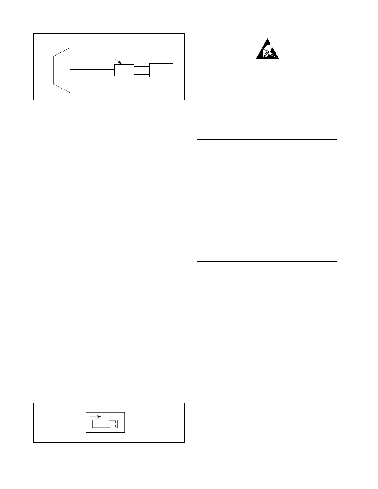
2. OPTIONS
Rate is automatically configured from the Total Reach
dataport unit. Options are selected using the SW1 switch
as illustrated in Figure 3.
When 0 dB (SW1-1) is selected, the unit will transmit a 0
dB AMI signal across the four-wire interface toward the
customer DSU/CSU. When -10 dB is selected, the unit
will transmit a -10 dB AMI signal toward the DSU/CSU.
3. INSTALLATION
C A U T I O N !
SUBJECT TO ELECTROSTATIC DAMAGE
OR DECREASE IN RELIABILITY.
HANDLING PRECAUTIONS REQUIRED.
After unpacking the unit, immediately inspect it for
possible shipping damage. If damage is discovered,
file a claim immediately with the carrier, and then
contact ADTRAN Customer and Product Service
(CAPS). See Section 6, Warranty and Customer
Service.
CAUTION
Never install telephone wiring during a
lightning storm.
Never install telephone jacks in wet locations
unless the jack is specifically designed for wet
locations.
Never touch uninsulated telephone wires or
terminals unless the telephone line has been
disconnected at the network interface.
Total Reach dataports normally provide -130
V of span-powering voltage to the TRDDS-R.
Wiring
For indoor applications, the TRDDS-R can be housed
in a standard T400/T200 shelf or the ADTRAN T400/
T200 Single Mount Housing, part number 1212007L1.
The ADTRAN T400/T200 single environmental
housing, part number 1150087L1, is recommended for
outside plant applications. Connections are made using
screwdown terminals on the barrier strip located on the
housing. Frame ground is presented on pins 1, 11, 17,
and 27 to accommodate various T400/T200
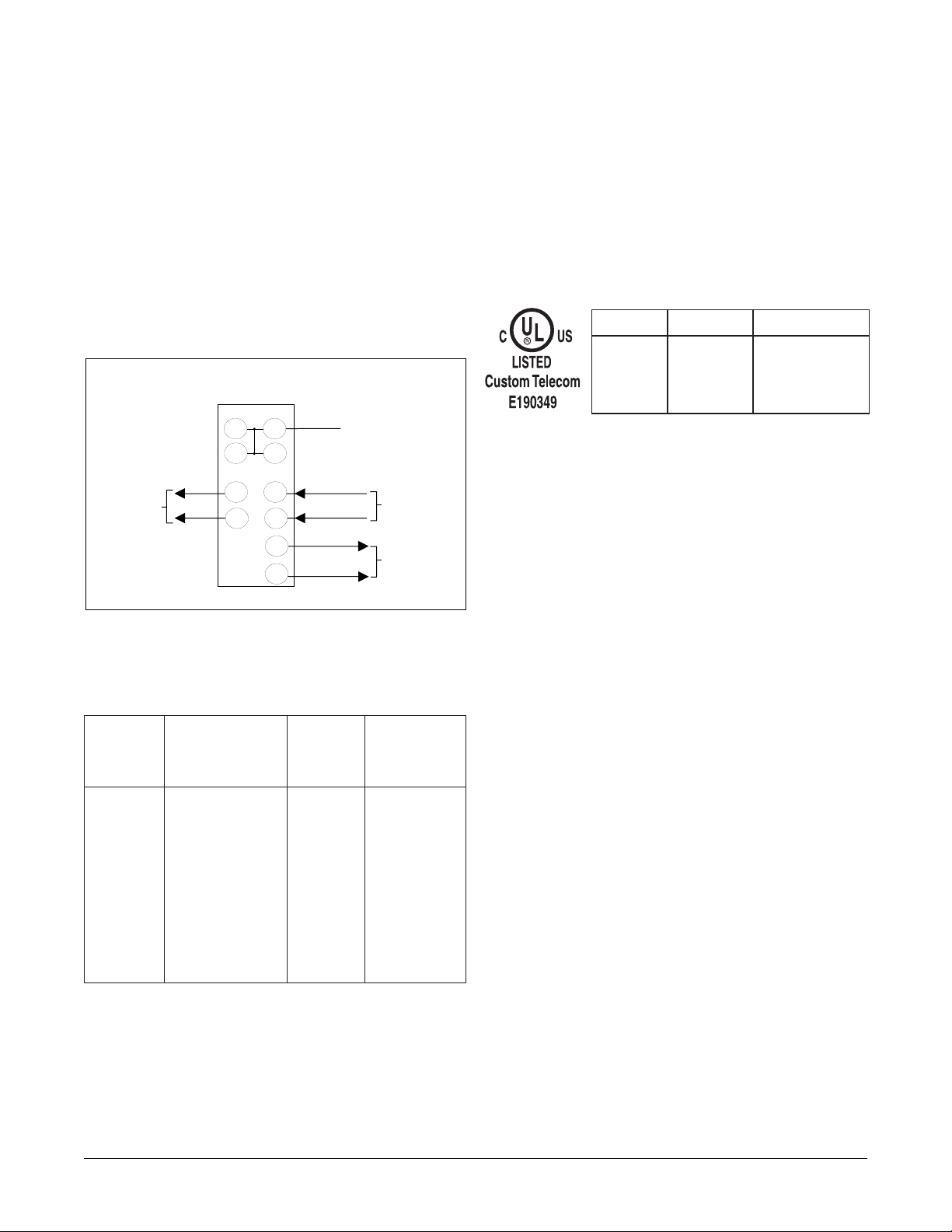
mountings. Figure 4 describes the circuit card pinout
and Table 1 shows the wiring connections for the
TRDDS-R for both inside and outside mounting
applications.
O
N
0dB -10dB
1
SW1
Figure 3. TRDDS-R Option Switch
Page 2 61291021L5-5ASection 61291021L5-5A, Issue 1
Page 3
The unit should be wired as follows:
• Network pair to terminal strip TT and TR positions
• To Customer and From Customer pairs through
customer 8-pin modular connector
or
To Customer (DRT, DRR) and From Customer
(DTT, DTR) to designated terminal strip positions
Electrical Code Compliance
Table 2 shows the UL/CUL Telecommunications Codes
for the TRDDS-R. The TRDDS-R complies with the
requirements covered under UL 1459 third edition and is
intended to be installed in an enclosure with an
Installation Code (IC) of “B” or “E”. The TRDDS-R is
intended for installation in restricted access locations
only.
No rate selection is necessary for the TRDDS-R. The
unit automatically adapts to the service rate of the Total
Reach dataport in the Central Office (CO).
TRDDS-R
Frame Ground
11
1
17
27
To
Network
(TT)
41 55
(TR) (DTR)
47 49
15
(DTT)
(DRT)
5
(DRR)
From
Customer
To
Customer
Figure 4. Circuit Card Pin Assignments
Table 1. Wiring Connections
lanimreT
riaP
pirtS
snoitangiseD
morF/oT
RT,TT74,14
004T
niP
rebmuN
84JR
krowteN
oT
RRD,TRD51,58,7
remotsuC
)xR(
morF
TTD,RTD55,942,1
remotsuC
)xT(
Table 2. UL/CUL Telecommunications Codes
TUPNITUPTUO
CIA -
CTX X
CPC C
Display Indicators
The TRDDS-R contains faceplate-mounted LED
indicators which display the operating status and service
rate. The indicators are described in Table 3.
Signal Meter
The TRDDS-R contains a signal meter that approximates
the amount of dB loss on the TRDDS loop at 13.3 kHz
(135 Ω termination), the Nyquist frequency of TRDDS.
The signal meter on the TRDDS-R may be used to verify
that the loop loss is actually within TRDDS deployment
guidelines without the requirement of peripheral test
equipment. The signal meter is activated automatically
upon power up during the TRDDS training sequence and
remains activated until synchronization occurs (usually
remotsuC
30-90 seconds after power-up). For example, if the signal
meter only illuminates the 2.4 LED, then the loop loss is
too great for TRDDS deployment. If the signal meter
illuminates 2.4 and 4.8 (only two LEDs), then the
TRDDS loop loss is between 50 and 56 dB and the loop is
considered marginal for TRDDS deployment. If three or
more rate LEDs are illuminated during TRDDS train-up,
then the circuit is considered to be within TRDDS
deployment guidelines. See Figure 5 for a translation of
the signal meter loss ranges in dB. If the loop loss
indicates a marginal loop for TRDDS deployment, then a
more precise loop loss measurement can be made with the
appropriate test equipment.
Page 361291021L5-5A Section 61291021L5-5A, Issue 1
Page 4

Table 3. Faceplate Indicators
rotacidnIsutatSnoitanalpxE
NO
neerG
CNYS
deR
snoitidnoc
puderewopsitinU
htiwdezinorhcnyS
PDUCORT
htiwdezinorhcnystoN
rofkcehc;PDUCORT
dna,sliocdaol,ytiunitnoc
enillamronbarehto
LED SIGNAL LOSS
(dB)
SC
64
56
19.2
9.6
4.8
2.4
Signal level indicated during
synchronization
0-10
10-20
20-30
30-40
40-50
50-56
>56
Signal level
ehtnoderuccosrorrE
maertsatadgnimocni
CRCRAENNO
CRCRAFNO
NO
KBL
CSNOlennahCyradnoceS
46NOdelbaneetaratadspbk46
65NOdelbaneetaratadspbk65
2.91NOetaratadspbk2.91
6.9NOetaratadspbk6.9
8.4NOetaratadspbk8.4
4.2NOdelbaneetaratadspbk4.2
gnihsalF
urhT-ssaP
delbane
delbane
delbane
delbane
suoiverpehtgnirud
rofkcehc;dnoces
snoitidnocenillamronba
R-SDDRTehtotresolc
ehtdrawotderuccosrorrE
tropatadhcaeRlatoT
suoiverpehtgnirud
rofkcehc;dnoces
snoitidnocenillamronba
OCehtotresolc
detavitcasikcabpooL
krowtensdrawot
takcabpoollanoitceridiB
ataD,tropatadhcaeRlatoT
Figure 5. Signal Loss Indication
Table 4. TRDDS-R and Total Reach Dataport
Loopback Interoperability Matrix
SDDhcaeRlatoT
stropataD
kcabpooLR-SDDRT
esnopseR
,4L,3L,2L,1L6001921
,2L5015241,2L5010141
EIN
,1L5013341,2L5010341
4L5013341,3L5013341
)tseWSU(5L6001921
EINdnaUCO
)tseWSU(2L5013341
4. TESTING
Loopback Testing
Loopback tests can be performed from the CO to verify
proper loop and TRDDS-R operation. The TRDDS-R
features auto-detection capability to determine the model of
Total Reach dataport installed in the central office. This
feature allows the TRDDS-R to support multiple loopback
applications. See Table 4 for an interoperability matrix of
loopback responses supported by the TRDDS-R. The
TRDDS-R always provides an NIE latching loopback at all
rates. See Table 5 and 6 for latching and alternating loopback
sequences. The TRDDS-R supports testing of the two-wire
loop from the remote end when the CO unit is performing a
bidirectional loopback.
Page 4 61291021L5-5ASection 61291021L5-5A, Issue 1
Page 5

Table 5. Latching Loopback Sequences
noitcnuFedoCetyB
gnitsixeraelC
skcabpool
ninoitisnarT
)PIT(ssergorp
0101110*
ecivedyfitnedI
depoolebot
tceleskcabpooL
)CSL(edoc
UCO-1010101*
USC-1000110*
EIN-1000001*
Initiating OCU Latching Loopback to Loop the
TRDDS-R (US West Only)
forebmuN
devieceR
setyB
• SW1-6 on the TRDDS-DP must be ON to enable
latching loopback response.
• From a test system or set, send an OCU latching
fomuminiM
setybPIT53
loopback sequence.
• Send a selected test pattern and test for error-free
operation.
• Upon completion of this test, advance to
fomuminiM
setybCSL53
Terminating OCU, CSU or NIE Latching
Loopback for latching loopback termination.
Initiating CSU Latching Loopback to Loop a
DSU/CSU (US West Only)
;pooloteraperP
edocPAMdnes
setyb03retfa
)EBL(
0110101*
etavitcA
kcabpool
)VEF(
0101101*
delbanekcabpooL
EBL001
setyb
eciovdnE-raF
VEF23
setyb
elbasidotderiuqersetybPIT53fomuminiM
.kcabpoolgnihctaldehsilbatse
tiberaCt'noD*
Table 6. Alternating Loopback Sequences
noitcnuFsetyBdevieceR
kcabpoolevitcA
UCO-0101010*
USC-0001010*
USD-0011010*
dnakcabpoolniatniaM
srorretibroftset
edockcabpool
:elpmaxe
0101010*/1DDDDDD*
kcabpoolraelC
atadevitucesnocruoF
edockcabpool
tiberact'noD*
fomuminiM
• SW1-6 on the TRDDS-DP must be ON to enable
latching loopback response.
• From a test system or set, send a CSU latching
loopback sequence. This instructs the TRDDS-
fomuminiM
DP to notify the TRDDS-R of a CSU loopback
request. The TRDDS-R will reverse sealing
current to the DSU/CSU. The DSU/CSU should
loop when reversed sealing current is detected.
• Send a selected test pattern and test for error-free
operation.
• Upon completion of this test, advance to
Terminating OCU, CSU or NIE Latching
Loopback for latching loopback termination.
Network Interface Equipment Latching
Loopback
The NIE latching loopback method can be used to loop
the TRDDS-R at all rates. This loopback test may
fosetybevitucesnocruoF
edockcabpooldeificeps
require programming of the loopback select code or
the complete sequence into the test system.
Terminating OCU, CSU or NIE Latching
Loopback
• From a test system or set, send a Latching
htiwgnitanretlaetybataD
Loopback Disable command (35 TIP bytes).
Total Reach Dataport Bidirectional Loopback
Support
The Total Reach dataport will execute a bidirectional
loopback when performing a loopback at the dataport.
The Total Reach dataport responds to either the OCU
deificepsatuohtiwsetyb
or DS0 loopback command, whichever loopback is
applicable to the dataport version. Refer to Table 7 for
Total Reach dataport loopback support.
Page 561291021L5-5A Section 61291021L5-5A, Issue 1
Page 6

Table 7. Total Reach Dataport Loopbacks
Total Reach
Dataport
SDDhcaeRlatoT
stropataD
SDDhcaeRlatoT
skcabpooLtropataD
,4L,3L,2L,1L6001921
,2L5015241,2L5010141
UCO
1L5013341,2L5010341
4L5013341,3L5013341
)tseWSU(5L6001921
0SD
)tseWSU(2L5013341
If the TRDDS-R detects a bidirectional loopback during
power-up synchronization, the TRDDS-R allows data to pass
on the four-wire interface by entering pass-thru mode. This
permits a standard, portable DDS test set, connected to the
four-wire customer interface of the TRDDS-R, to verify the
integrity of the two-wire loop by transmitting a test pattern
and examining the returning data for synchronization and
errors. The TRDDS-R LBK indicator always flashes during
a Total Reach dataport bidirectional loopback in the pass-thru
mode. Refer to Figure 6 for an illustration of the bidirectional
loopback pass-thru mode.
Total Reach
Dataport
TRDDS-R
Test Unit
Data
Pass-Thru
Bidirectional
loopback
Figure 6. Total Reach Dataport Bidirectional
Loopback Pass-Thru Mode
TRDDS-R
Bidirectional
loopback
X
X
Open Loop
DSU/CSU
Figure 7. Total Reach Dataport Bidirectional
Loopback Normal Mode
5. DEPLOYMENT GUIDELINES
The TROCU DP and TRDDS-R use technology intended
to eliminate the need for repeaters and concerns over
impairments caused by typical noise and bridged tap.
Listed below are the loop design guidelines for TRDDS
(see Tables 8 and 9 for more information):
• All loops must be nonloaded.
• Actual Measured Loss (AML) should not exceed 50
dB at 13.3 kHz (135 Ω termination), the Nyquist
frequency of TRDDS.
NOTE
The 50 dB AML limit includes 6 dB of signal
margin to account for potential near-end cross
talk (NEXT) from other digital services that may
be provisioned in the same binder group.
• Loop length should not exceed 50 kft.
• Bridged tap length should not exceed 12 kft.
• Background noise level should not exceed
34 dBrn.
• Impulse noise should not exceed
-40 dBm, (+50 dBrn).
If a Total Reach dataport bidirectional loopback is invoked
after the TRDDS-R achieves synchronization, the TRDDS-R
will not pass or receive data from the CPE or DDS test set.
This is consistent with current DDS testing methods and is
referred to as the Total Reach dataport bidirectional loopback
normal mode. For testing purposes, the installer may choose
to initiate the TRDDS-R to pass-thru mode. Once the
Measure noise with 50 kbit weighting
characteristic approximating a filter with a
passband of 40 Hz to 30 kHz. Background noise
level or impulse noise level is referenced from 56/
64 kbps data rate in TR62310.
bidirectional loopback is executed in normal mode, unseat
and reseat the TRDDS-R and allow the unit to train-up. Once
trained, the TRDDS-R will revert to pass-thru mode for
further testing. Refer to Figure 7 for TRDDS operation
during bidirectional loopback in normal mode.
Page 6 61291021L5-5ASection 61291021L5-5A, Issue 1
NOTE
Page 7

Table 8. Cable Type and Temperature Loss Data @ 13.3 kHz
ELBACCITSALPtfk/SSOLBdELBACREPAPtfk/SSOLBd
)F0(CIPeguaG91
)F07(CIPeguaG91
)F021(CIPeguaG91
)F0(CIPeguaG22
)F07(CIPeguaG22
)F021(CIPeguaG22
)F0(CIPeguaG42
)F07(CIPeguaG42
)F021(CIPeguaG42
)F0(CIPeguaG62
)F07(CIPeguaG62
)F021(CIPeguaG62
2035.0
3806.0
0166.0
219.0
8520.1
5101.1
1752.1
2893.1
7194.1
3286.1
8658.1
8179.1
Table 9. TRDDS Insertion Loss Measurements
SDDRT
ecivresSDD
eniL
noitarugifnoC
zHk3.31@zHk82@
)F0(PLUPeguaG91
)F07(PLUPeguaG91
)F021(PLUPeguaG91
)F0(PLUPeguaG22
)F07(PLUPeguaG22
)F021(PLUPeguaG22
)F0(PLUPeguaG42
)F07(PLUPeguaG42
)F021(PLUPeguaG42
)F0(PLUPeguaG62
)F07(PLUPeguaG62
)F021(PLUPeguaG62
6165.0
5146.0
5596.0
4549.0
6060.1
0731.1
0092.1
4234.1
8625.1
1576.1
9648.1
8069.1
6. WARRANTY AND CUSTOMER SERVICE
ADTRAN will replace or repair this product within 10
years from the date of shipment if it does not meet its
lanoitidartrofzHk82otderapmoczHk3.31
published specifications or fails while in service (see
ADTRAN Carrier Network Equipment Warranty,
Repair, and Return Policy and Procedure, document
60000087-10A).
Contact Customer and Product Service (CAPS) prior to
GWA62tfk72Bd21.05Bd53.56
returning equipment to ADTRAN.
For service, CAPS requests, or further information,
GWA42tfk52.63Bd00.05Bd05.26
contact one of the following numbers:
ADTRAN Technical Support
GWA22tfk05Bd42.05Bd33.95
(800) 726-8663
Standard hours: Monday-Friday, 7 a.m.-7 p.m. CST
Emergency hours: 7 days/week, 24 hours/day
ADTRAN Sales
(800) 827-0807
ADTRAN Repair/CAPS
(256) 963-8722
Repair and Return Address
ADTRAN, Inc.
Customer & Product Service (CAPS) Department
901 Explorer Boulevard
Huntsville, Alabama 35806-2807
Page 761291021L5-5A Section 61291021L5-5A, Issue 1
 Loading...