

Page 1

TRACER 4305
System Manual
12804305L1A TRACER 4305 System (Plan A)
12804305L1B TRACER 4305 System (Plan B)
612804305L1A-1A
May 2002
Page 2

Trademarks
Any brand names and product names included in this manual are trademar ks, registered trademarks, or
trade names of their respe ctive holders.
To the Holder of the Manual
The contents of this ma nual are c urrent as of the dat e of publi cation. ADTRAN rese rves the r ight to c hange
the contents without prior notice.
In no event will ADTRAN be liable for any special, incidental, or consequential damages or for
commercial losses even if ADTRAN has been advised thereof as a result of issue of this publication.
901 Explorer Boulevard
P.O. Box 140000
Huntsville, AL 35814-4000
Phone: (256) 963-8000
©2002 ADTRAN, Inc.
All Rights Reserved.
Printed in U . S . A .
Page 3

About this Manual
This manual provides a complete description of the TRACER 4305 system and system software.
The purpose of this manual is to provide the technician, system administrator, and manager with
general and specific information related to the planning, installation, operation, and maintenance of the
TRACER 4305. This manual is arranged so that needed information can be quickly and easily found. The
following is an overview of the contents.
Section 1 System Description
Provides managers with an overview of the TRACER 4305 system.
Section 3 Microwave Path Engineering Basics
Explains the basics of analyzing a wireless microwave link, or path. The significant
parameters are defi ned, and several recommendations are offered.
Section 3 Engineering Guidelines
Provides informat ion to assist network designers wit h incor porating the
TRACER 4305 system into their networks.
Section 4 Network Turnup Procedure
Provides step-by-st ep instru ctions on ho w to instal l the TRACER 4305 uni t, determi ne the
parameters for t he syst em, i nst all the network and option modules, and power up the
system.
Section 5 User Interface Guide
Explains the terminal interface and provides a description for each of the menus available
for the TRACER 4305 system.
Section 6 Troubleshooting Guide
Provides helpful information for troubleshooting common configuration problems for the
TRACER 4305 system.
Revision History
This is the 1st issue of this manual.
612804305L1A-1A © 2002 ADTRAN, Inc. 3
Page 4
Notes provide additional useful information.
Cautions signify infor m ation that could prevent service interru ption.
Warnings provide information that could prevent damage to the equipment or
endangerment to human life.
Safety Instructions
When using your telephone equipment, please follow these basic safety precautions to reduce the risk of
fire, electr ical shock, or personal injury:
1. Do not use this product near water, such as a bathtub, wash bowl, kitchen sink, laundry tub, in a
wet basement, or near a swimming pool.
2. Avoid using a telephone (other than a cordless-type) during an electrical storm. There is a remote
risk of shock from lightning.
3. Do not use the telephone to report a gas leak in the vicinity of the leak.
4. Use only the power cord, power sup ply, and/or batt eries in dicated in the manual. Do not dispose of
batteries in a fire. They may explo de. Ch eck with local codes for speci al disposal instructions.
Save These Important Safety Instructions
4 © 2002 ADTRAN, Inc. 612804305L1A-1A
Page 5
Federal Communications Commission Radio Frequency Interference Statement
This equipment has been tested and found to comply with the limits for a Class A digital device, pursuant
to Part 15 of the FCC Rules. These limits are designed to provide reasonable protection against harmful
interference when the equipment is operated in a commercial environment. This equipment generates,
uses, and can radiate radio frequency energy and, if not installed and used in accordance with the
instruction manua l, may cause harmful interferen ce to radio frequencies. Operation of this equipment in a
residential area is l ikely t o cause har mful inte rference in which case the us er will be required to correc t the
interference at his own expense.
Shielded cables must be used with this unit to ensure compliance with Class A FCC limits.
Changes or modifications to this unit not expressly approved by the party
responsible for compliance could void the user’s authority to operate the equipment.
612804305L1A-1A © 2002 ADTRAN, Inc. 5
Page 6

Warranty and Customer Service
ADTRAN will repair and return this pr oduct within fi ve years from t he date of shipment if it does not meet
its published specifications or fails while in service. F or detailed warranty, repair, and return information
refer to the ADTRAN Equipment Warranty and Repair and Return Policy Procedure.
Return Material Authorization (RMA) is required prior to returning equipment to ADTRAN.
For service, RMA requests, or further information, contact on e of the numbers listed at the end of thi s
section.
LIMITED PRODUCT WARRANTY
ADTRAN warrants that for five years from the date of shipment to Customer, all products manufactured
by ADTRAN will be free from defects in materials and workmanship. ADTRAN also warrants that
products will conform to the applicable specifications and drawings for such products, as contained in the
Product Manual or in ADTRAN's int ernal specifications and draw ings for such products (which may or
may not be reflected in the Product Ma nual). This warranty only applies if Customer gives ADTRAN
written notice of defects duri ng the wa rrant y perio d. Upon such notice, ADTRAN will, at its optio n, either
repair or replace the defective item. If ADTRAN is unable, in a reas onable time, to repair or replace any
equipment t o a condition as warranted, Customer is e ntitled to a full refund of the purchase price upon
return of the equipment to ADTRAN. This warranty applies only to the original purchaser and is not
transferable without ADTRAN's express written permission. This warranty becomes null and void if
Customer modifies or alt er s t he equipment in any way, other than as spe cifically authorized by ADTRAN.
EXCEPT FOR THE LIMITED WARRANTY DESCRIBED ABOVE, THE FOREGOING
CONSTITUTES THE SOLE AND EXCLUSIVE REMEDY OF THE CUSTOMER AND THE
EXCLUSIVE LIABILITY OF ADTRAN AND IS IN LIEU OF ANY AND ALL OTHER W ARRANTIES
(EXPRESSED OR IMPLIED). ADTRAN SPECIFICALLY DISCLAIMS ALL OTHER WARRANTIES,
INCLUDING (WITHOUT LIMITATION), ALL WARRANTIES OF MERCHANTABILITY AND
FITNESS FOR A PARTICULAR PURPOSE. SOME STATES DO NOT ALLOW THE EXCLUSION
OF IMPLIED WARRANTIES, SO THIS EXCLUSION MAY NOT APPLY TO CUSTOMER.
In no event will ADTRAN or its suppliers be liable to the Customer for any incidental, special, punitive,
exemplary or consequential damages experienced by either the Customer or a th ird party (including, but
not limited to, loss of data or information, loss of profits, or loss of use). ADTRAN is not liable for
damages for any cause whatsoever (whether based in contract, tort, or otherwise) in excess of the amount
paid for the item. Some states do no t allow the lim itation or exclusion of liability for incide ntal or
consequential damages, so the above limitation or exclusion may not apply to the Customer.
6 © 2002 ADTRAN, Inc. 612804305L1A-1A
Page 7

Customer Service, Product Support Information, and Training
ADTRAN will repair and return this product if within five years from the date of shipment the product
does not meet its published specification or the product fails while in service.
A return material authorization (RMA) is required prior to returning equipment to ADTRAN. For service,
RMA requests, training, or more information, use the contact information given below.
Repair and Return
If you determ in e that a repair is needed, please contact our Customer and Product Service (CA PS)
department to have an RMA number issued. CAPS should also be contacted to obtain information
regarding equipment currently in house or possible fees associated with repair.
CAPS Department (256) 963-8722
Identify the RMA number clearly on the package (below address), and return to the following address:
ADTRAN Customer and Product Service
901 Explorer Blvd. (East Tower)
Huntsville, Alabama 35806
RMA # _____________
Pre-Sales Inquiries and Applications Support
Your reseller should serve as the f irst point of con tact for su pport. If addit ional pre-s ales s upport is ne eded,
the ADTRAN Support web site provides a variety of support services such as a searchable knowledge
base, latest product documentation, application briefs, case studies, and a link to submit a question to an
Applications Engineer. All of this, and more, is available at:
http://support.adtran.com
When needed, further pre-sales assistance is available by calling our Applications Engineering
Department.
Applications Engineering (800) 615-1176
612804305L1A-1A © 2002 ADTRAN, Inc. 7
Page 8

Post-Sale Support
Your reseller should serve as the first point of contact for support. If additional support is needed, the
ADTRAN Support web site provides a variety of support services such as a searchable knowledge base,
updated firmware releases, latest product documentation, service request ticket generation and
trouble-shooting tools. All of this, and more, is available at:
http://support.adtran.com
When needed, further post-sales assistance is available by calling our T echnical Support Center. Please
have your unit serial number available when you call.
Technical Support (888) 4ADTRAN
Installation and Maintenance Support
The ADTRAN Custom Extended Services (ACES) program offers multiple types and levels of installation
and maintenance services which allow you to choose the kind of assistance you need. This support is
available at:
http://www.adtran.com/aces
For questi on s, call the ACES H elp Desk.
ACES Help Desk (888) 874-ACES (2237)
Training
The Enterprise Network (EN) Technical Trai ning Department of fers train ing on our most popula r products.
These courses include overviews on product features and functions while covering applica tions of
ADTRAN's product lines. ADTRAN provides a variety of training options, including customized training
and courses taught at our fac iliti es or at your site. Fo r more infor mation ab out trainin g, pleas e conta ct y our
Territory Manager or the Enterprise T raining Coordinator.
Training Phone (800) 615-1176, ext. 7500
Training Fax (256) 963-6700
Training Email training@adtran.com
8 © 2002 ADTRAN, Inc. 612804305L1A-1A
Page 9

Radio Frequency Interface Statement
This equipment has been tested and foun d to comply with the li mits for an intent io nal radiato r, pursuant to
Part 15, Subpart C of the FCC Rules. This equipment generates, uses, and can radiate radio frequency
energy. If not installed and used in accordance with the instructions, it may cause interference to radio
communications.
The limits are desig ned to provi de reasona ble protec tion agai nst such int erference i n a residen tial sit uation.
However, there is no guarantee that interference will not occur in a particular installation. If this equipment
does cause interference to radio or television reception, which can be determined by turning the equipment
on and off, the user is encouraged to try to correct the interference by one or more of the following
measures:
• Reorient or rel o cate the receiving antenna o f the affected radio or televisio n .
• Increase the separation between the equipment and the affected receiver.
• Connect the equipment and the affected receiver to power outlets on separate circui ts.
• Consult the dealer or an experienced radio/TV technician for help.
Changes or modifications not expressl y approved by ADTRAN coul d void the user’ s
authority to operate the equipment.
612804305L1A-1A © 2002 ADTRAN, Inc. 9
Page 10

FCC Output Power Restrictions
The FCC does not require licensing to implement this device. However, the FCC has established
restrictions regarding maximum Effective Isotropic Radiating Power (EIRP) and the adjustments required
when employing directional gain antennas. (Refer to “Setting the Transmitter Power” in Section 2 of this
manual). These restric ti ons are detailed in FCC Part 15. 407( a) (3). It is the responsibi lity of the individuals
designing and implement ing the radio sys tem to ass ure compliance wi th these and an y other pert inent FCC
Rules and Regulations. This device must be professionally installed.
Exposure to Radio Frequency Fields
The TRACER 4305 is designed to operate at 5.725 to 5.825 GHz with 100 mW maximum transmit power.
This level of RF energy is below the Maximum Permissible Exposure (MPE) levels specified in FCC OET
65:97-01. The installa tion of high gain antenna equi p ment in the system configuration may create the
opportunity for exposure to levels higher than recommended for the general population at a distance less
than 15 feet (4.6 meter) from the center of the antenna. The following pr eca utions must be taken duri ng
installati on of this equipm en t:
• The installe d antenna must not be loc ated in a manner t hat all ows exposur e of th e gener al popul ation to
the direct beam path of the antenna at a distance less than 15 feet (4.6 meters). Installation on towers,
masts, or rooftops not accessible to the genera l population is recommended; or
• Mount the antenna in a manner that prevents any personnel from entering the area within 15 feet (4. 6
meter) from the front of the antenna.
• It is recommended that the installer place radio frequency hazard warnings signs on the barrier that
prevents access to the antenna.
• Prior to installing the antenna to the TRACER 4305 output, make sure the power is adjusted to the
settings specified in sec tion 2 of this manual.
• During antenna installation, be sure that power to the TRACER equipment is turned off in order to
prevent any energy presence on the coaxial connector .
• During installation and alignment of the antenna, do not stand in front of the antenna assembly.
• During installation and alignment of the antenna, do not handle or touch the front of the antenna.
These simple precautions must be taken to prevent general population and installation personnel from
exposure to RF energy in excess of specified MPE levels.
10 © 2002 ADTRAN, Inc. 612804305L1A-1A
Page 11

SYSTEM DESCRIPTION
This section of ADTRAN’s TRACER 4305 System manual is designed for use by network engineers,
planners, and designers for overview information about the TRACER 4305.
It contains general information and describes physical and operational concepts, network relationships,
provisioning, testi ng, alarm stat us, and system monitoring. This se ction shou ld be used in con junction wi th
Section 2, Engineering Guideli nes , of the system manual.
CONTENTS
System Overview . . . . . . . . . . . . . . . . . . . . . . . . . . . . . . . . . . . . . . . . . . . . . . . . . . . . . . . . . . . . . . . 12
Features and Benefits . . . . . . . . . . . . . . . . . . . . . . . . . . . . . . . . . . . . . . . . . . . . . . . . . . . . . . . . . . . 12
Configuration and Management . . . . . . . . . . . . . . . . . . . . . . . . . . . . . . . . . . . . . . . . . . . . . . . . . 12
Operational . . . . . . . . . . . . . . . . . . . . . . . . . . . . . . . . . . . . . . . . . . . . . . . . . . . . . . . . . . . . . . . . . 12
612804305L1A-1A © 2002 ADTRAN, Inc. 11
Page 12

Section 1, System Descript ion TRACER 4305 System Manual
1. SYSTEM OVERVIEW
The ADTRAN TRACER® 4305 wireless data system provides transparent extension of DS3 circuits over
wireless links for up to 10 mi le s (line-of-sight path required). As authorized under Part 15.407 of the FCC
Rules, the TRACER 4305 operates license-free in the 5.8 GHz unlicensed National Information Infrastructure (U-NII) band, requiring no FCC licensing of end users.
For configuration and testing, the TRACER 4305 provides the capability to control the remote TRACER
4305 through a separate maintenance channel. The TRACER 4305 has several built-i n test capabilities
including remote loopback. Complete configuration and perfor mance data is available through menus
accessed using a standard RS-232 terminal interface.
2. FEATURES AND BENEFITS
The following is a brief list of TRACER 4305 features and benefits:
Configuration and Management
• Easy to use VT100 control port (RS-232 interface) for configuration and monitoring
• Remote configuration
Operational
• Transparent DS3 transmi ssion over digital microwave link
• No license required per FCC Rules Part 15.407
• Frequency: 5.725 to 5.825 GHz
• Point-to-point, up to 15 miles
• 1-U high unit for easy rack-mounting
12 © 2002 ADTRAN, Inc. 612804305L1A-1A
Page 13

MICROWAV E PATH ENGINEER IN G BASICS
CONTENTS
Line-of-site . . . . . . . . . . . . . . . . . . . . . . . . . . . . . . . . . . . . . . . . . . . . . . . . . . . . . . . . . . . . . . . . . . . . 14
Decibels . . . . . . . . . . . . . . . . . . . . . . . . . . . . . . . . . . . . . . . . . . . . . . . . . . . . . . . . . . . . . . . . . . . . . . . 14
Receiver Power . . . . . . . . . . . . . . . . . . . . . . . . . . . . . . . . . . . . . . . . . . . . . . . . . . . . . . . . . . . . . . . . . 15
Path Loss . . . . . . . . . . . . . . . . . . . . . . . . . . . . . . . . . . . . . . . . . . . . . . . . . . . . . . . . . . . . . . . . . . . . . 16
Antenna Alignment . . . . . . . . . . . . . . . . . . . . . . . . . . . . . . . . . . . . . . . . . . . . . . . . . . . . . . . . . . . . . . 17
Antenna Beam Patterns . . . . . . . . . . . . . . . . . . . . . . . . . . . . . . . . . . . . . . . . . . . . . . . . . . . . . . . 17
Fresnel Zones, Earth Curvature, & Antenna Heights . . . . . . . . . . . . . . . . . . . . . . . . . . . . . . . . . 18
Coaxial Cable . . . . . . . . . . . . . . . . . . . . . . . . . . . . . . . . . . . . . . . . . . . . . . . . . . . . . . . . . . . . . . . . . . 19
Receiver Sensitivity . . . . . . . . . . . . . . . . . . . . . . . . . . . . . . . . . . . . . . . . . . . . . . . . . . . . . . . . . . . . . 19
Fade Margin . . . . . . . . . . . . . . . . . . . . . . . . . . . . . . . . . . . . . . . . . . . . . . . . . . . . . . . . . . . . . . . . . . . 19
Path Availability . . . . . . . . . . . . . . . . . . . . . . . . . . . . . . . . . . . . . . . . . . . . . . . . . . . . . . . . . . . . . . . . 20
ADTRAN Link Analyzer . . . . . . . . . . . . . . . . . . . . . . . . . . . . . . . . . . . . . . . . . . . . . . . . . . . . . . . . . . 21
FIGURES
Figure 1. Example Microwave Path with Parameters . . . . . . . . . . . . . . . . . . . . . . . . . . . . . . . . . . 17
Figure 2. Typical Antenna Beam Pattern . . . . . . . . . . . . . . . . . . . . . . . . . . . . . . . . . . . . . . . . . . . 18
TABLES
Table 1. Path Loss for Given Path Lengths . . . . . . . . . . . . . . . . . . . . . . . . . . . . . . . . . . . . . . . . . 16
Table 2. Minimum Antenna Height for Given Path Lengths . . . . . . . . . . . . . . . . . . . . . . . . . . . . . 18
Table 3. Typical Coaxial Loss for Common Cable Types, per Foot . . . . . . . . . . . . . . . . . . . . . . . 19
612804305L1A-1A © 2002 ADTRAN, Inc. 13
Page 14

Section 2, Microwave Path Engineering Basics TRACER 4305 System Manual
1. LINE-OF-SITE
The TRACER 4305 system is designed for operation in the 5725 MHz to 5825 MHz unlicensed National
Information Infrastructure (U-NII) frequency band. Radio wave propagation in this band exhibits
microwave characteristics, which are ideally suited for point-to-point, line-of-sight communications.
Line-of-sight esse ntially requir es that t he transmitt ing ant enna and re ceiving a ntenna are able to “s ee” eac h
other, and that the straight-line path between the two antennas is free of any obstructions, such as
buildings, trees, mountains, and, in longer paths, even the curva ture of the earth.
Point-to-Point Wireless communication from a single site to another
individual site. Contrast with point-to-multipoint
Line-of-Sight An unobstructed, direct path ex is ts between the
transmitting and the receiving antennas.
2. DECIBELS
The received signal power equation is often expressed in a decibel (dB) format, which turns the power
multiplica tion and division operati ons into additi on and subtracti on operations. In general, any quantit y
can be expresse d in decibels. If the quantity (x) is a power level, the decibel equivalent is defined as
x
If the quantit y x is referenced to a mill iwatt (mW), then the decib el-milliwatt (dBm) is used inst ead of a
generic decibel.
x
dBm
dB
10 log10x()⋅=
10 log
⋅=
x
------------ -
10
1mW
(dB)
(dBm)
3. RECEIVER POWER
The radio frequency (RF) sig nal power that is availa ble at the in put to the rec eiving TRACER 43 05 system
is the next parameter of in terest in analyzing a wireless pa th. Per FCC 15.407 rules, the TRACER 4305 is
permitted a maximum output power level of 100 mW, which is equivalent to 20 dBm. This output signal
will be attenuated and distorted by various factors, all of which will degrade the original signal and affect
the signal strength and quality as sensed by the receiving unit. A simplified power budget analysis is
beneficial to perform after verifying a suitable line-of-sight path to determine if the microwave path is
suitable, even for ideal, non-distorted signals.
The equation relating received signal power to the other microwave parameters is
P
---------------------------=
R
4π()2d2L
PTGTGRλ
2
(watts, W)
14 © 2002 ADTRAN, Inc. 612804305L1A-1A
Page 15

TRACER 4305 System Man ual Section 2, M icr owav e Pat h Engi nee ring Ba si cs
where the variables in the equa tion are defined as
P
R
P
T
G
T
G
R
received power (Watts)
transmitted power (100 mW (max) for TRAC E R 4305 - adjusta ble)
transmit antenna gain
receive antenna gain
λ carrier wavelength (c / ƒ) (meters)
d path distance (meters)
L other losses (RF coaxial cable, etc.)
The transmitted power is limited for the 5.8 GHz U-NII band to a maximum of 30 dBm. The actual
transmit and receive anten n a gain values are strictly dependent upon the physical characteristics of the
antennas installed for each link. Typical gains are between 20 and 30 dB. For example, a 4 foot diameter,
flat panel C-band antenna from a popular antenna manufacturer advertises a gain of 23.5 dB. The carrier
wavelength is the physical wavelength of the main RF carri er being used for communication , and is
usually approximated at the center frequency of the band, which is 5787.5 MHz. This g ives a wavelength
of 5.18 cm.
The path distance is simply the physical dis ta nce between the transmit and receive antennas. For the
TRACER 4305 these distances can range up to 15 miles. The final parameter L incorporates all other
signal power losses in the m icrowave link, m ost of which are ca used by antenna feed.
4. OUTPUT POWER
Transmit ted power limitati ons for th e 5.8 GHz U-NII band is gove rned by the Eff ective Is otropi c Radiat ed
Power (EIRP) of the system. Per FCC 15.407 rules, the TRACER 4305 is permitted a maximum EIRP of
53 dBm. EIRP can be calculated using the following equation
(dB)
where P
EIRP PTGTLF–+=
is the transmitted power (in dBm), GT is the transmit antenna gain (in dB), and LF is the feedline
T
loss (in dB).
For example, a TRACER 4305 system transmittin g at 20 dBm will r esult in the followin g restrictions on
antenna gain:
53dBm 20dBm GTLF–+≤
GTLF–33dBi≤
(dB)
(dB)
Since antenna gain is directly affected by antenna size, an EIRP restriction of 53 dBm will limit antenna
selection. However, per FCC ru les EIRP is calculated for the tot al system (transmitter, feedline, and
antenna), an d additiona l antenna gain ma y be used to compensate for feedline loss. In some cases, addin g
additional length to your feedline cable will permit you to select a larger antenna. Refer to Table 3 on page
19 for a listing of coaxial loss for common cable types (per foot).
612804305L1A-1A © 2002 ADTRAN, Inc. 15
Page 16

Section 2, Microwave Path Engineering Basics TRACER 4305 System Manual
5. PATH LOSS
The expression
2
4πd
L
--------- -
==
P
λ
4πdf
----------- -
2
(watts, W)
c
where
f carrier frequency (Hz)
λ carrier wavelength (c / f) (meters)
d path distance (meters)
c speed of light, free-space (meters)
is called the path loss, and i ncr eases rapidly as ei ther pat h lengt h incre ase s or carr ier wavel ength decreas es
(which happens as the carrier frequency increases). So, longer microwave paths will naturally experience
more path loss than shorter paths. Likewise, higher frequency microwave communication will experience
more path loss than lower frequency microwave communication.
Table 1 tabulates path loss values f or various path lengths f or t h e TRACE R 4305 system. Values not listed
in the table can be interpolated from those listed.
Table 1. Path Loss for Given Path Lengths
Path Length
(miles)
1112
2118
3121
4124
5126
10 132
15 135
Path Loss
(dB)
When using decibel notation, the received power equation becomes
4πdf
P
PTGTGRL– 20 · log
=
R
–++
----------- -
10
c
(dB)
or
P
PTGTGRL– LP–++=
R
Where, in the second equation the path loss has been lumped into a single quantity, L
(dB)
, as discussed
P
previously. W hen using decibel notation, it is necessary that all quantities are individually converted to
16 © 2002 ADTRAN, Inc. 612804305L1A-1A
Page 17
TRACER 4305 System Man ual Section 2, M icr owav e Pat h Engi nee ring Ba si cs
P
L
L
decibels prior to pe rforming addition and subtraction.
When d is expressed in miles and f in GHz, the path loss expression in decibels becomes
L
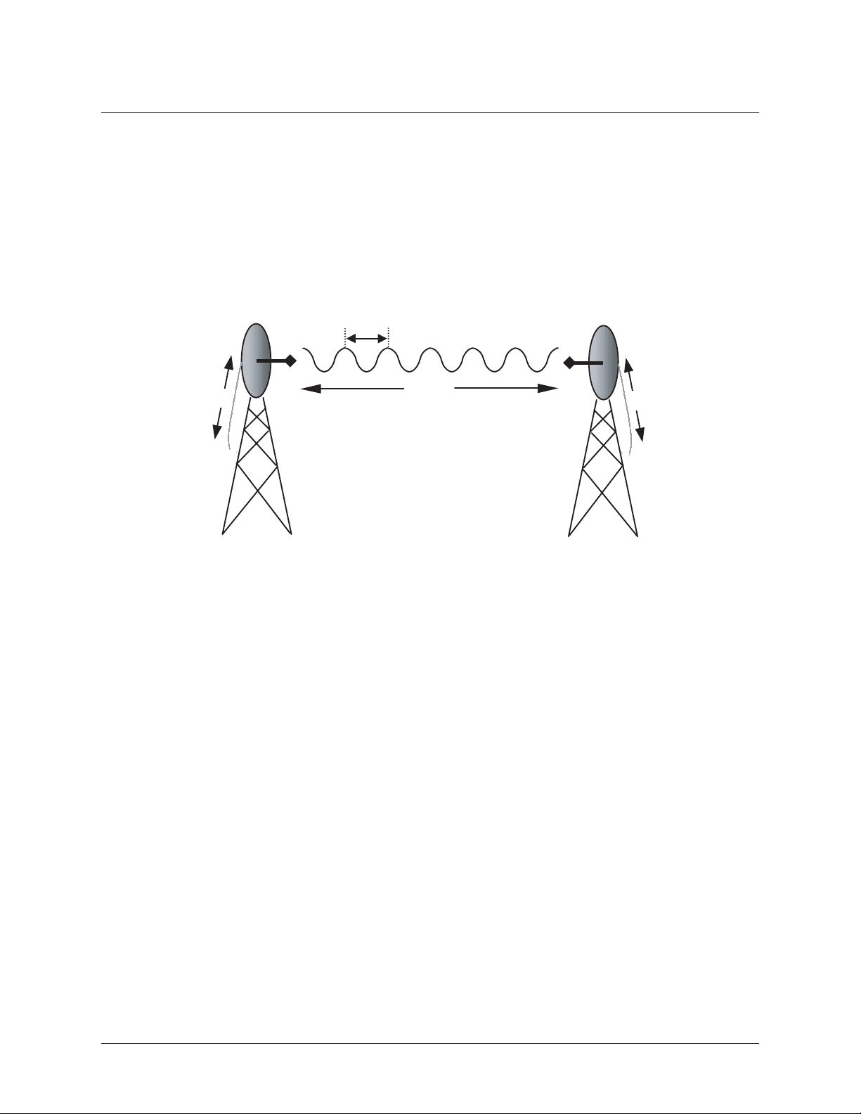
Figure 1 illu strates a wireless link contai n i n g all of the parameters previou s ly discussed.
96.6 20 log10d() 20·log+
P
G
T
T
Figure 1. Example Microwave Path with Parameters
f()⋅+=
10
λ
d, L
P
(dB)
G
R
P
R
6. ANTENNA ALIGNMENT
With line-of-sight microwave communications, optimum system performance requires that the
transmitting and re ceiving a ntennas are properly aligned. This will ensure maximum r eceived s ignal power
at each receiver. Antenna alignment must be achieved in both azimuth (along a horizontal plane) and
elevation (alo ng a vert ical plane). A receiv ed signal strength indic at or (RSSI) is used to aid the equipmen t
installer in determining when alignment is maximized, by simply ensuring maximum RSSI. The RSSI
indicator for the TRACER 4305 system is provided through the VT100 terminal menus accessed through
the RS-232 interf ace, and is presented as a series of bars indi cating signal stren gth. More bars means more
RSSI, which ensures more received signal strength and better link performance.
If the remote syst em has acquired a useful signal fr om the remote system, then the remote TRACER 4305
RSSI can also be viewed from the local TRACER 4305 VT100 terminal menu interface.
Antenna Beam Patterns
Directly related to the subject of antenna alignment is the topic of antenna beam patterns. Antennas being
used with the TRACER 4305 system will have a particular beam shape determined in part by the physical
construction and geometry of the antenna. The antenna beam patterns are characterized by a dominant
main lobe, which is the preferred lobe to use for point-to-point communications, and several side lobes, as
shown in Figure 2 on p age 18 . The a ntenna ali gnment step to se ttin g u p a mi crowave link is in f act s teer ing
the main lobes of bot h antennas until the main lobe of one transmitter is centered on the receiving element
of the receiving antenna.
612804305L1A-1A © 2002 ADTRAN, Inc. 17
Page 18

Section 2, Microwave Path Engineering Basics TRACER 4305 System Manual
main lobe
side lobes
Figure 2. Typical Antenna Beam Pattern
Antennas are also designed to radiate RF energy efficiently for a specific range of frequencies. Please
consult the data sheet fo r your partic ular antenn a make and model to ensu re that it is spe cified to ope rate in
the 5725 MHz to 5825 MHz frequency band.
Fresnel Zones, Earth Curvature, & Antenna Heights
The Fresnel zones correspond to regions in the microwave path where reflections of the intended signal
occur and combine in both constructive and destructive manners with the main signal, thereby either
enhancing or reducing the net power at the receiver.
In general, the odd numbered Fresnel zones (1, 3, 5, ...) add constructively at the receiver, while the even
numbered Fresnel zones (2, 4, 6, ...) add destructively at the receiver.
The first Fresnel zone corresponds to the main lobe, and must be at least 60% free of physi cal obstructions for
the path calculations to be valid. Since the main lobe contains the vast majorit y of the microwave energy, this
zone is typically used to determine proper antenna heights when placing antennas on towers or buildings.
The curvature of t he Earth b ecomes a le gitima te obstr uction fo r path le ngths of 7 miles o r greate r , and must
also be accounted for when determining minimum antenna heights.
The aggregate expression for minimum antenna height that incorporates both the 60% first Fresnel zone
and the Earth curvature is given by
h 72.1
d
---- - 0.125d
+= (feet)
2
4f
where f is in G H z and d is in miles.
Table 2 tabulates minimum antenna heights for given path lengths.
Table 2. Minimum Antenna Height for Given Path Length s
Path Length
(miles)
222
432
641
850
10 60
14 81
Min. Antenna Height
(ft)
18 © 2002 ADTRAN, Inc. 612804305L1A-1A
Page 19

TRACER 4305 System Man ual Section 2, M icr owav e Pat h Engi nee ring Ba si cs
7. COAXIAL CABLE
Coaxial cable wil l be req uired to attach the TRACER 43 05 to the antenna. The length of the c able will var y
from a few fee t to several feet, depending upon your app lication an d the proximity of th e TRACER 4305
to the antenn a.
Various grades of coaxial cable will work sufficiently we ll for connecting the TRACER 4305 unit to the
antenna. A low-loss coaxial cable is suggested to minimize cable losses. One end of the cable will require
an N-type male connector (plug) to mate with the TRACER 4305 unit. The other end of the coax will
require a conne ctor compat ible wi th the a ntenna ch osen fo r the i nstall ation, whi ch is us ually al so an N-t ype
male connector (plug). Additionally, it is recommended that both connectors on the coaxial cable be
weatherproofed from the elements to prevent corrosion and electrical shorting.
Ta ble 3 gives typic al los s figures for some of the more co mmon coax ial cable types, per foot
Table 3. Typical Coaxial Loss for Common Cable Types, per Foot
Cable Ty pe Cable Loss (dB/ft)
RG-213, RG-214, RG-393
RG-142
RG-58, RG-223
RG-174, RG-316
0.2
0.3
0.4
0.7
In certain areas where lightning strikes are frequent, a lightning arrestor can be installed directly on the
antenna. This w ill help protect th e RF electron ics in the downstream path fro m d amaging voltages and
currents, including the TRACER 4305 unit.
8. RECEIVER SENSITIVITY
Receiver sensitivity is a value expressed in decibels referenced to one milliwatt (dBm) that corresponds to
the minimum amount of signal power needed at the receiver to achieve a given bit error rate (BER).
Receiver sensitivity is usually a negative number of decibels, and as such smaller receiver sensitivity is
better for a given BER. Several factors affect rec eiver sensitivity, including the data bandwidth of the
wireless link, and the amount of additional signal degradation introduced in the receiver electronics. The
receiver sensitivit y of the TRACER 4305 is -78 dBm at 10
-6
BER.
9. FADE MARGIN
Fade margin is a value indicating the amount of extra signal power available to the receiver to operate at a
maximum bit error rate (BER). Higher levels of fade margin are better, and will protect the viability of the
microwave link against signal fading. Fade margin is simply the difference between the available signal
power at the receiver an d the rece iver sensitivity, discussed previously:
FPRP
– PRGTGRL– LP– P
sens
–++==
sens
(dB)
612804305L1A-1A © 2002 ADTRAN, Inc. 19
Page 20

Section 2, Microwave Path Engineering Basics TRACER 4305 System Manual
10. PATH AVAILABILITY
The path availability of a wireless link is a metric that expresses the fractional amount of time a link is
available over so me f ixe d am ount of time, and depends on several factors. Path availability is expressed as
A 1 2.5 10
×()abfd310
6–
F 10⁄–
()–[]100%×=
(dB)
where the parameters are
a terrain factor
b climate factor
f carrier frequency (GHz)
d path length (miles)
F fade margin (dB)
The terrain factor is a quantity that compensates the link availability for different types of terrain.
Generally speaking, the more smooth an area's terrain is, the less availability a wireless link running over
that terrain will ha ve, prima rily du e to multipa th ref lecti ons. In c ontra st, seconda ry micro wave sign als wil l
be randomly dispersed over rough te rrain, and will not int erfere with t he main signa l lobe as badl y as in the
smooth terrain case. The terrain factor values normally used are listed below:
Terrain Terrain Factor Description
Smooth 4 water, flat desert
Average 1 moderate roughness
Mountainous 1/4 very rough, mountainous
The climate factor is a quantity that compensates the link availability for different types of climates
(weather). In genera l, mi crowave links operating in areas with high humidity will have less availability
than those in arid areas, primarily because water is a dispersive mechanism to microwave energy, and
causes the main signal lobe to refract and dispe rse away from the receive r location. The climate factor
values normally used are listed below.
Climate Climate Factor Description
Very Dry 1/8 desert regions
Temperate 1/4 mainland, interior region
Humid 1/2 humid and coas tal r egi ons
20 © 2002 ADTRAN, Inc. 612804305L1A-1A
Page 21

TRACER 4305 System Man ual Section 2, M icr owav e Pat h Engi nee ring Ba si cs
11. ADTRAN LINK ANALYZER
A very useful program is available on the Internet that can be used as a simp le power budget calcula tor to
determine if a link is suitable for use with the TRACER 4305 system. The program is a JAVA applet that
runs in an Internet browser window, and can be accessed at http://www.adtranwireless.com by clicking
on the Link Analyzer icon.
To accurately model system parameters with regard to the TRACER 4305 system, the following Link
Analyzer options should be set as follows:
5.8 GHz Band (select this button )
RF Mounting Options Rack Mounted (both ends)
RF to Antenna Cable Type ¼ in (15.5 dB/100 ft)
RF to Antenna Cable Length (change to actual length, e.g. 10 ft)
Refer to the Link Analyzer help file for more information on how to use the program.
More comprehensive microwave path analysis software packages exist, and can be used to gain a very
detailed feasibility study for physical locations.
612804305L1A-1A © 2002 ADTRAN, Inc. 21
Page 22

Section 2, Microwave Path Engineering Basics TRACER 4305 System Manual
22 © 2002 ADTRAN, Inc. 612804305L1A-1A
Page 23

ENGINEERING GUIDELINES
CONTENTS
Equipment Dimensions . . . . . . . . . . . . . . . . . . . . . . . . . . . . . . . . . . . . . . . . . . . . . . . . . . . . . . . . . . 24
Power Requirements . . . . . . . . . . . . . . . . . . . . . . . . . . . . . . . . . . . . . . . . . . . . . . . . . . . . . . . . . . . . 24
Reviewing the Front Panel Design . . . . . . . . . . . . . . . . . . . . . . . . . . . . . . . . . . . . . . . . . . . . . . . . . 24
RSSI Monitoring Interface. . . . . . . . . . . . . . . . . . . . . . . . . . . . . . . . . . . . . . . . . . . . . . . . . . . . . . 24
TX PWR Monitoring Interface . . . . . . . . . . . . . . . . . . . . . . . . . . . . . . . . . . . . . . . . . . . . . . . . . . . 25
Front Panel LEDs . . . . . . . . . . . . . . . . . . . . . . . . . . . . . . . . . . . . . . . . . . . . . . . . . . . . . . . . . . . . 25
Reviewing the TRACER 4305 Rear Panel Design . . . . . . . . . . . . . . . . . . . . . . . . . . . . . . . . . . . . . 26
Antenna Interface . . . . . . . . . . . . . . . . . . . . . . . . . . . . . . . . . . . . . . . . . . . . . . . . . . . . . . . . . . . . 27
Fuse . . . . . . . . . . . . . . . . . . . . . . . . . . . . . . . . . . . . . . . . . . . . . . . . . . . . . . . . . . . . . . . . . . . . . . 27
DC Power Connection. . . . . . . . . . . . . . . . . . . . . . . . . . . . . . . . . . . . . . . . . . . . . . . . . . . . . . . . . 27
Alarm Contacts . . . . . . . . . . . . . . . . . . . . . . . . . . . . . . . . . . . . . . . . . . . . . . . . . . . . . . . . . . . . . . 28
DS3 (In and Out) Connection . . . . . . . . . . . . . . . . . . . . . . . . . . . . . . . . . . . . . . . . . . . . . . . . . . . 28
RS-232 Connection (Terminal Use) . . . . . . . . . . . . . . . . . . . . . . . . . . . . . . . . . . . . . . . . . . . . . . 28
RS-232 Connection (Modem Use) . . . . . . . . . . . . . . . . . . . . . . . . . . . . . . . . . . . . . . . . . . . . . . . 30
At-A-Glance Specifications . . . . . . . . . . . . . . . . . . . . . . . . . . . . . . . . . . . . . . . . . . . . . . . . . . . . . . . 31
FIGURES
Figure 1. TRACER 4305 Front Panel Layout . . . . . . . . . . . . . . . . . . . . . . . . . . . . . . . . . . . . . . . . 24
Figure 2. TRACER 4305 Rear Panel Layout. . . . . . . . . . . . . . . . . . . . . . . . . . . . . . . . . . . . . . . . . 27
TABLES
Table 1. TRACER 4305 Front Panel Description . . . . . . . . . . . . . . . . . . . . . . . . . . . . . . . . . . . . . 25
Table 2. TRACER 4305 LEDs . . . . . . . . . . . . . . . . . . . . . . . . . . . . . . . . . . . . . . . . . . . . . . . . . . . .25
Table 3. DC Power Connector Pinout . . . . . . . . . . . . . . . . . . . . . . . . . . . . . . . . . . . . . . . . . . . . . . 27
Table 4. Alarm Contact Connector Pinout . . . . . . . . . . . . . . . . . . . . . . . . . . . . . . . . . . . . . . . . . . . 28
Table 5. RS-232 Connection Pinout . . . . . . . . . . . . . . . . . . . . . . . . . . . . . . . . . . . . . . . . . . . . . . . 29
Table 6. TRACER 4305 (DCE) to Terminal (DTE) Diagram . . . . . . . . . . . . . . . . . . . . . . . . . . . . . 29
Table 7. TRACER 4305 (DCE) to Personal Computer (DB-9) . . . . . . . . . . . . . . . . . . . . . . . . . . . 29
Table 8. TRACER 4305 (DCE) to Modem (DCE) . . . . . . . . . . . . . . . . . . . . . . . . . . . . . . . . . . . . . 30
612804305L1A-1A © 2002 ADTRAN, Inc. 23
Page 24

Section 3, Engineering G ui del ine s TRACER 4305 System Manual
1. EQUIPMENT DIMENSIONS
The TRACER 4305 unit is 19” W, 10.5” D, and 1.75” H, weighs 7 lbs, and can be used in rack-mount
configurations.
2. POWER REQUIREMENTS
The TRACER 4305 system has a maximum power consumption of 25W and a maximum current draw of
1.2A (at 21 VDC).
3. REVIEWING THE FRONT PANEL DESIGN
The front panel contains a single control switch for activating a DS3 line loopback, RSSI and TX PWR
monitoring interface s, a GND interface fo r connectin g the TRACER 4305 system to an exte rnal ground ing
source, and status LEDs t o provide vi sual infor mation about the TRACER 4305 sys tem. Figu re 1 ident ifies
the DS3 loopback switch, the various bantam interfaces, and the LEDs.
DS3 Loopback
Status LEDs
Switch
RSSI
Figure 1. TRACER 4305 Front Panel Layout
TX PWR
GND
RSSI Monitoring Interface
The RSSI voltage is a function of the signal strength at the receiver and is used to measure the received
signal strength. RSSI varies approximately from 0 to greater than 4 Volts (V), with 0V corre spondi ng to a
weaker received signal and 4V or better corresponding to a stronger received signal.
The voltage level present at the RSSI test point represents only a relative signal level of
receiv e strength f rom the far end. No direct correlation can be mad e between RSSI volt age
levels and actual receive levels in dBm. This test point is provided to assess rel ative signal
level for alignmen t of antennas.
24 © 2002 ADTRAN, Inc. 612804305L1A-1A
Page 25

TRACER 4305 System Manual Section 3, Engineering Guidelines
TX PWR Monitoring Interface
The TX PWR voltage is a function of the selec ted transmit power level. This volta ge ranges appr oximately
from 0 to 5V, with 0V corresponding to 0 dBm (1 milliwatt) and 5V corresponding to +20 dBm (100
milliwatts).
Front Panel LEDs
With the TRACER 4305 powered-on, the front panel LEDs provide visual information about the status of
the TRACER 4305 system. Table 1 provides a brief description of the front panel features, and Table 2
(continued on page 27) provides detailed information about the LEDs.
Table 1. TRACER 4305 Front Panel Description
Feature Description
DS3 Loopback Switch Allows quick activation/deactivation of DS3 line loopbacks
RSSI Interface DC voltage indicating strength of the received signal at the antenna
TX PWR Interface DC voltage indicating strength of transmitted signal
GND Interface Connect to an external earth ground source
Status LEDs Provides status information about the system
Table 2. TRACER 4305 LEDs
For these LEDs... This color light... Indicates that...
PWR Green (solid) the TRACER 4305 is connected to a power source.
Off the TRACER 4305 is not currently powered up.
PLAN A Green (solid) the TRACER 4305 is transmitting on Frequency Plan A.
Off the TRACER 4305 is not transmitting on Frequency
Plan A.
PLAN B Green (solid) the TRACER 4305 is transmitting on Frequency Plan B.
Off the TRACER 4305 is not transmitting on Frequency
Plan B.
RF DOWN Red (solid) there is a communication problem between the local and
remote TRACER 4305 systems.
RF LOW Red (solid) the RSSI level is below suggested minimum threshold.
TST Amber (solid) unit is performi ng power- on se lf- test.
RAI Red (solid) the TRACER 4305 received a remote alarm in the DS3 EOC
channel (bits X1 and X2 are both set to zero).
612804305L1A-1A © 2002 ADTRAN, Inc. 25
Page 26

Section 3, Engineering G ui del ine s TRACER 4305 System Manual
Table 2. TRACER 4305 LEDs (Continued)
For these LEDs... This color light... Indicates that...
AIS Red (solid) the TRACER 4305 received a remote alarm from a connected
DS3 device (properly aligned and framed alternating one-zero
pattern).
LOF Red (solid) the TRACER 4305 DS3 framer has lost alignment (due to
receiving too many F or M bits in error).
LOS Red (solid) the TRACER 4305 does not detect a DS3 from the connected
DS3 device signal (indicated by receiving 192 consecutive
zeros).
BPV Red (solid) the TRACER 4305 detects Bipolar Violations on the received
signal from the connected DS3 device (receiving two
consecutive “one” bits with the same polarity).
LBK Amber (solid) the TRACER 4305 is currently in DS3 line loopback.
Amber (flashing) the TRACER 4305 is currently in DS3 link loopback.
4. REVIEWING THE TRACER 4305 REAR PANEL DESIGN
The TRACER 4305 rear panel contains the following interfaces:
A
•
•
DC P
•
DS3 I
• Antenna (N-Type connector) for the antenna feedline cable
• Ground lug for connecting to earth ground
•
RS232 (DB-25 female) for connecti ng to a VT100 te rminal or PC wit h terminal e mulation softwar e
Figure 2 on page 27 identifies the various fe a tures of the TRACER 4305 rear panel. A detailed discussion
of all interfaces (including pinouts, where applicable) follows the figure.
interface (terminal bl ock) for connecting to an external alarm moni toring system
LARM
(terminal block) for connecting to a proper 21-63 VDC power source
OWER
and OUT (BNC interfaces) for connecting to a DS3 device
N
26 © 2002 ADTRAN, Inc. 612804305L1A-1A
Page 27

TRACER 4305 System Manual Section 3, Engineering Guidelines
RS232 Interface
(VT100 Terminal)
DS3 In
(Receive)
DS3 Out
(Transmit)
Alarm
Contacts
Figure 2. TRACER 4305 Rear Panel Layout
DC Power Connection
Fuse
Antenna Interface
Ground
Lug
Antenna Interface
The A
NTENNA
antenna feedline cable. When determining the cable specifications for your application, refer to Section 3,
Microwave Pat h Engi neering Basics (Coaxial Cable on page 19) for a discussion on cable length and loss
factors.
interface (N-Type connector) connects to the antenna (customer supplie d) usi ng standard
Fuse
The fuse holder, accessible from the rear panel of the TRACER 4305, accepts a generic 1 Amp, 2-inch
slow-blo fus e.
DC Power Connection
The TRACER 4305 can operate from a supply between 21 and 63 VDC, with either polarit y refer enced to
ground, and consumes less than 25 Watts (W). Power supplies should be able to provide up to 30 W at
the selected voltage. Current required (in amps) is determined by dividing the power consumed (in watts)
by the applied voltage (in volts). For example, at 48 V, TRACER 4305 would draw approximately 0.52 A
(25 W/48 V).
Connector type Terminal Block
Table 3. DC Power Connector Pinout
PIN NAME DESCRIPTION
1 + POSITIVE LEAD (referenced to ground)
2 - NEGATIVE LEAD (referenced to ground)
612804305L1A-1A © 2002 ADTRAN, Inc. 27
Page 28

Section 3, Engineering G ui del ine s TRACER 4305 System Manual
Alarm Contacts
Normally open (NO) and normally closed (NC) alarm contacts are provided on the rear panel of the
TRACER 4305 system. In normal operation, the NC contact is electrically connected to the common
contact (COM) and the NO contact is isolated. During an alarm condition, the NC contact becomes
isolated and the NO is electrically connected to COM. This allows alarm conditions to be reported to
external alarm monitoring systems.
Connector type Terminal Block
Table 4. Alarm Contact Connector Pinout
PIN NAME DESCRIPTION
1 COM COMMON CONTACT
2 NO NORMALLY-OPEN CONTACT
3 NC NORMALLY-CLOSED CONTACT
DS3 (In and Out) Connection
The physical DS3 interface is provided by a pair of 75 Ω BNC connectors for transmit and receive.
The shielding on both BNC connectors are grounded per ANSI T1.404.
RS-232 Connection (Terminal Use)
The RS-232 connector provi des a female DB-25 terminal c onnection (wired as a DCE int er face), which is
used for terminal access to the TRACER 4305 system. The RS-232 port provides the following functions:
• Accepts EIA-232 input from a PC or terminal for controlling the TRACER 4305 system
• Operates at 9600 bps
T abl e 5 o n p age 29 shows th e pino ut. Wiring diagrams for connectin g to th e RS-232 conne ctor (for vari ous
applications) are provided following the pinout.
28 © 2002 ADTRAN, Inc. 612804305L1A-1A
Page 29

TRACER 4305 System Manual Section 3, Engineering Guidelines
Connector type (USOC) DB-25
Table 5. RS-232 Connection Pinout
PIN NAME DESCRIPTION
1, 7 GND GROUND
2 TX TRANSMIT
3 RX RECEIVE
4 RTS REQUEST TO SEND
5 CTS CLEAR TO SEND
6 DSR DATA SET READY (MODEM CONTROL ONLY )
8 CD CARRIER DETECT
9-19 — UNUSED
20 DTR DATA TERMINAL RE ADY (MODE M CONTROL ONLY)
21 — UNUSED
22 RI RING INDICATOR
23-25 — UNUSED
Table 6. TRACER 4305 (DCE) to Terminal (DTE) Diagram
PIN NAME PIN NAME
2TX 2 TX
3RX 3 RX
4 RTS 4 RTS
5 CTS 5 CTS
6 DSR 6 DSR
7 GND 7 GND
Table 7. TRACER 4305 (DCE) to Personal Computer (DB-9)
PIN NAME PIN NAME
2TX 3 RX
3RX 2 TX
4 RTS 7 RTS
5 CTS 8 CTS
6 DSR 6 DSR
7 GND 5 GND
612804305L1A-1A © 2002 ADTRAN, Inc. 29
Page 30

Section 3, Engineering G ui del ine s TRACER 4305 System Manual
RS-232 Connection (Modem Use)
Modem controls, discussed in Section 5, User Interface Guide, of this manual, will enable or disable
modem control through the RS-232 int erf ace. When this option is enabled from a standard termina l
connection, all RS-232 communicat ions will cease until a modem is att ached with a null modem adapter
between the TRACER 4305 and the data modem. The data modem should be configured for AUTO
ANSWER and 9600 bps. When the user connects via modem to the TRACER 4305 unit, communica ti ons
via the RS-232 p ort will res ume. If a us er a cciden tall y enabl es mode m co ntrol fro m a te rminal an d dis rupts
the RS-232 communication, pressing <Ctrl + Z> three times will temporarily disable the modem control
option (until the system is reset) and access the system c onfiguration to disable modem control.
The TRACER 4305 must be interfaced to a modem via an RS-232 null modem adapter or cable. The null
modem will convert Clea r To Send (CTS) and Data Set Ready (D SR) in to Ready To Send (R TS) and Data
Terminal Ready (DTR), respectively. These signals will indicate (to mos t modems) that a valid DTE
terminal device is pre sent. The null modem interf ace must rout e Carrier Detect (CD) on pi n 8 direct ly from
the modem, and the modem must source CD only when actually connected to a carrier when using the
RS-232 interface for modem control.
When
M
ODEM CONNECTION
DSR for a time greater than 20 ms. The null modem will consequently drop DTR and RTS at the modem
interface, signaling the modem to hang up the line. If password functionality is enab led in the TRACER
4305, selecting
M
ODEM CONNECTION
is selected in the menu system, the TRACER 4305 will de-assert DTR and
will rest the TRACER 4305 to the password entry screen.
Hangup-on-DTR-drop may need to be explicitly enabled on some modems.
Table 8 contains the wiring diagram needed for connecting the TRACER 4305 RS-232 interface to a
modem using the null modem adapter.
Table 8. TRACER 4305 (DCE) to Modem (DCE)
PIN NAME PIN NAME
2TX 3 RX
3RX 2 TX
4 RTS 5 CTS
5 CTS 4 RTS
6DSR 20 DTR
7 GND 7 GND
8CD 8 CD
30 © 2002 ADTRAN, Inc. 612804305L1A-1A
Page 31

TRACER 4305 System Manual Section 3, Engineering Guidelines
5. AT-A-GLANCE SPECIFICATIONS
The following is a list of specifications for the TRACER 4305 system.
Hardware Description Specification
Transmitter
Output Power +20 dBm, max
Frequency Range 5725 to 5825 MHz
Receiver
Receive Level, Range -30 to -78 dBm
Receive Level, Maximum -30 dBm
Receive Level, Nominal -55 dBm
Frequency Plan
Plan A Tx 5.750 GHz, Rx 5.800 GHz
Plan B Tx 5.800 GHz, Rx 5.750 GHz
DS3 Interface
User Inte rface
VT100 Terminal Interface
Capacity 44.736 Mbps
Connection dual 75 Ω BNC connectors (Tx and Rx)
Line Code B3ZS
Framing M13, C-Bit Parity
Alarms AIS, Red, Yellow, BPVs
Loopbacks Local and remote (line and link)
Diagnostics DS3 Line and Link Loopbacks
Test Points RSSI, Tx PWR
Data Rate 9600 bps
Data Bits 8
Parity None
Stop Bits 1
Terminal Emulation VT 100
612804305L1A-1A © 2002 ADTRAN, Inc. 31
Page 32

Section 3, Engineering G ui del ine s TRACER 4305 System Manual
Hardware Description Specification
Mechanical and Envir onmental
Operating Temperature -25ºC to 65ºC
Size 19” W x 10.5” D x 1.75” H
Humidity 95%, Non-condensing
Weight 7 lbs
Power
Input Voltage 21 to 63 VDC, either polarity
referenced to ground
Power Consumption <
25 Watts
Connector 2 pin terminal block (DC)
Fuse 1 amp, 250 Volt slow-blo fuse (2-inch)
32 © 2002 ADTRAN, Inc. 612804305L1A-1A
Page 33

NETWORK TURNUP PROCEDURE
CONTENTS
Introduction . . . . . . . . . . . . . . . . . . . . . . . . . . . . . . . . . . . . . . . . . . . . . . . . . . . . . . . . . . . . . . . . . . . . 34
Tools Required . . . . . . . . . . . . . . . . . . . . . . . . . . . . . . . . . . . . . . . . . . . . . . . . . . . . . . . . . . . . . . . . . 34
Unpack and Inspect the System . . . . . . . . . . . . . . . . . . . . . . . . . . . . . . . . . . . . . . . . . . . . . . . . . . . 34
Contents of ADTRAN Shipment . . . . . . . . . . . . . . . . . . . . . . . . . . . . . . . . . . . . . . . . . . . . . . . . . 34
Customer Provides . . . . . . . . . . . . . . . . . . . . . . . . . . . . . . . . . . . . . . . . . . . . . . . . . . . . . . . . . . . 34
Channel Selection . . . . . . . . . . . . . . . . . . . . . . . . . . . . . . . . . . . . . . . . . . . . . . . . . . . . . . . . . . . . . . 35
Grounding Instructions . . . . . . . . . . . . . . . . . . . . . . . . . . . . . . . . . . . . . . . . . . . . . . . . . . . . . . . . . . 35
Supplying Power to the Unit . . . . . . . . . . . . . . . . . . . . . . . . . . . . . . . . . . . . . . . . . . . . . . . . . . . . . . 36
Mounting Options . . . . . . . . . . . . . . . . . . . . . . . . . . . . . . . . . . . . . . . . . . . . . . . . . . . . . . . . . . . . . . . 36
Connecting the DS3 Interface . . . . . . . . . . . . . . . . . . . . . . . . . . . . . . . . . . . . . . . . . . . . . . . . . . . . . 36
FIGURES
Figure 1. Bandwidth Division. . . . . . . . . . . . . . . . . . . . . . . . . . . . . . . . . . . . . . . . . . . . . . . . . . . . . 35
612804305L1A-1A © 2002 ADTRAN, Inc. 33
Page 34

Section 4, Network Turnup Procedure TRACER 4305 System Manual
1. INTRODUCTION
This section discusses the installation process of the TRACER 4305 system.
Changes or modifications not expressly approved by ADTRAN could void the user’s
authority to operate the equipment.
2. TOOLS REQUIRED
The tools required for the installation of the TRACER 4305 are:
• VT100 term inal or PC with terminal emulat ion software
• RS-232 (DB-25 male for TRACER 4305 end) cable for connecting to terminal
T o pr ev ent ele ctrical shock, do not in stall equ ipment in a wet locati on or duri ng a lig htning
storm.
3. UNPACK AND INSPECT THE SYSTEM
Each TRACER 4305 is shipped in its own cardboard shipping carton. Open each carton carefully and
avoid deep penetration into the carton with sharp objects.
After unpacking the unit, inspect it for possible shipping damage. If the equipment has been damaged in
transit, immediately file a claim with the carrier, then contact ADTRAN Customer Service (see Warranty
and Customer Service information in the fron t of this manual) .
Contents of ADTRAN Shipment
Your ADTRAN shipment includes the following items:
• TRACER 4305 unit
• TRACER 4305 Documentation CD
Customer Provides
The following items are necessary for the installation of the TRACER 4305 system and are not provided
by ADTRAN:
• 21 to 63 VDC power source (or AC adapter available fr om ADTRAN P/N 1280650L1), either polari ty
referenced to ground
• Antenna and mounting hardware
• Antenna feedline cable
• DS3 cables (BNC for TRACER 4305 end) for connecting to DS3 equipment
34 © 2002 ADTRAN, Inc. 612804305L1A-1A
Page 35

TRACER 4305 System Manual Section 4, Network Turnup Proc ed ur e
4. CHANNEL SELECTION
The FCC has allocated 100 MHz of spectrum in the band in which the TRACER 4305 operates. Figure 1
illustrates the ba n dwidth division.
A
5750 MHz
Channel Plan describes which lobe is transmitted upon.
Example: A will transmit at A lobe and receive at B.
Figure 1. Bandwidth Division
5800 MHz
B
T o desig nate the ut ilizat ion of the U- NII bandwidt h, there ar e two dif feren t channe l plans, l abeled A and B.
The letter of each channel plan setting is preset by the factory and refers to the physical configuration of
the diplexer filter inside the environmental housing. The transmitter at one end of the link will transmit in
the lower portion of the spectrum and receive in the upper portion. Consequently, the receiver at the other
end should receive in the lower portion and transmit in the upper portion. There is one rule for successful
TRACER 4305 configuration.
1. The letter of the chan nel plan must be dif ferent on both ends . Shipment of a link will consist of one
Plan A and Plan B unit.
5. GROUNDING INSTRUCTIONS
The following provides grounding instruction information from the Underwriters’ Laboratory UL 60950
Standard for Safety of Information Technology Equipment Including Electrical Business Equipment, of
December, 2000.
An equipment grounding conductor that is not smaller in size than the ungrounded branch-circuit supply
conductors is to be installed as part of the circuit that supplies the product or system. Bare, covered, or
insulated grounding conductors are acceptable. Individually covered or insulated equipment grounding
conductors shall have a continuous outer finish that is either green, or green with one or more yellow
stripes. The equipment grounding conductor is to be connected to ground at the service equipment.
The attachment-plug receptacles in the vicinity of the product or system are all to be of a grounding type,
and the equipment grounding conductors serving these receptacles are to be connected to earth ground at
the service equipment.
A supplementary equipment grounding conductor shall be installed between the product or system and
612804305L1A-1A © 2002 ADTRAN, Inc. 35
Page 36

Section 4, Network Turnup Procedure TRACER 4305 System Manual
ground that is in addition to the equipment gr ounding conductor in the power supply cord.
The supplementary equipment grounding conductor shall not be smaller in size than the ungrounded
branch-circuit supply conductors. The supplementary equipment grounding conductor shall be connected
to the product at the terminal provided, and shall be connected to ground in a manner that will retain the
ground connection when the product is unplugged from the receptacle. The connection to ground of the
supplementary equipment grounding conductor shall be in complianc e with the rules for terminating
bonding jumpers at Part K or Article 250 of the National Electrical Code, ANSI/NFPA 70. Termination of
the supplementary equipment grounding conductor is permitted to be made to building steel, to a metal
electrical raceway system, or to any grounded item that is permanently and reliably connected to the
electrical service equipment ground.
The supplemental ground ing conductor sha ll be connected to the equipment using a number 8 ring terminal
and should be fasten ed to the ground ing lu g provi ded on the r ear pa nel of the e quipment . Th e ring termi nal
should be installed using the appropriate crimping tool (AMP P/N 59250 T-EAD Crimping Tool or
equivalent.)
The supplemental equipmen t grounding terminal is located on the rear panel of the
TRACER 4305.
6. SUPPLYING POWER TO THE UNIT
The TRACER 4305 can operate from a supply between 21 and 63 VDC, with either polarit y refer enced to
ground. Power supplies should be able to provide up to 30 watts at the selected voltage. A dual pin
terminal plug accepts power at the rear panel of the unit, providing a
PWR pin and a GND point. Adapters
for this plug are available for the ADTRAN +48V power supply (P/N 1175043L2).
7. MOUNTING OPTIONS
Install the TRACER 4305 in a location t hat re quires mini mal ante nna fee dline length ( the lo ss in th is cabl e
directly affects overall system performance) . The TRACER 4305 is designed to be mounted in a rack. If
multiple units are installed in one location, no space is needed between units, but certain regulations may
require at least 0.75” of space above and below each unit.
8. CONNECTING THE DS3 INTERFACE
The physical DS3 interface is provided using a pair of 75 Ω BNC connectors for transmit and receive.
Using standard coaxial cable, conne ct the
interface of the DS3 equipment. Connect the
interface of the DS3 equipment.
DS3 OUT interface of the TRACER 4305 to the receive data
DS3 IN interface of the TRACER 4305 to the transmit data
36 © 2002 ADTRAN, Inc. 612804305L1A-1A
Page 37

USER INTERFACE GUIDE
CONTENTS
Navigating the Terminal Menu . . . . . . . . . . . . . . . . . . . . . . . . . . . . . . . . . . . . . . . . . . . . . . . . . . . . 38
Terminal Menu Window . . . . . . . . . . . . . . . . . . . . . . . . . . . . . . . . . . . . . . . . . . . . . . . . . . . . . . . 38
Navigating using the Keyboard Keys . . . . . . . . . . . . . . . . . . . . . . . . . . . . . . . . . . . . . . . . . . . . . 39
Terminal Menu and System Control . . . . . . . . . . . . . . . . . . . . . . . . . . . . . . . . . . . . . . . . . . . . . . . .39
Password Protection . . . . . . . . . . . . . . . . . . . . . . . . . . . . . . . . . . . . . . . . . . . . . . . . . . . . . . . . . . 39
Menu Descriptions . . . . . . . . . . . . . . . . . . . . . . . . . . . . . . . . . . . . . . . . . . . . . . . . . . . . . . . . . . . . . . 40
>TRACER System Status. . . . . . . . . . . . . . . . . . . . . . . . . . . . . . . . . . . . . . . . . . . . . . . . . . . . . . 40
>Main Menu . . . . . . . . . . . . . . . . . . . . . . . . . . . . . . . . . . . . . . . . . . . . . . . . . . . . . . . . . . . . . . . . 42
>TRACER System Configuration . . . . . . . . . . . . . . . . . . . . . . . . . . . . . . . . . . . . . . . . . . . . . . . . 43
>TRACER Link Performance History . . . . . . . . . . . . . . . . . . . . . . . . . . . . . . . . . . . . . . . . . . . . . 45
>DS3 Status/Configuration/Loopback. . . . . . . . . . . . . . . . . . . . . . . . . . . . . . . . . . . . . . . . . . . . . 46
>DS3 Performance History . . . . . . . . . . . . . . . . . . . . . . . . . . . . . . . . . . . . . . . . . . . . . . . . . . . . . 48
FIGURES
Figure 1. Main Menu Screen. . . . . . . . . . . . . . . . . . . . . . . . . . . . . . . . . . . . . . . . . . . . . . . . . . . . . 38
Figure 2. TRACER System Status . . . . . . . . . . . . . . . . . . . . . . . . . . . . . . . . . . . . . . . . . . . . . . . . 40
Figure 3. Main Menu . . . . . . . . . . . . . . . . . . . . . . . . . . . . . . . . . . . . . . . . . . . . . . . . . . . . . . . . . . . 42
Figure 4. TRACER System Configuration. . . . . . . . . . . . . . . . . . . . . . . . . . . . . . . . . . . . . . . . . . . 43
Figure 5. TRACER Link Performance History. . . . . . . . . . . . . . . . . . . . . . . . . . . . . . . . . . . . . . . . 45
Figure 6. DS3 Status/Configuration/Loopback . . . . . . . . . . . . . . . . . . . . . . . . . . . . . . . . . . . . . . . 46
Figure 7. DS3 Link Loopback . . . . . . . . . . . . . . . . . . . . . . . . . . . . . . . . . . . . . . . . . . . . . . . . . . . . 47
Figure 8. DS3 Line Loopback . . . . . . . . . . . . . . . . . . . . . . . . . . . . . . . . . . . . . . . . . . . . . . . . . . . . 48
Figure 9. DS3 Link Performance History. . . . . . . . . . . . . . . . . . . . . . . . . . . . . . . . . . . . . . . . . . . . 48
TABLES
Table 1. DS3 Interface Alarms . . . . . . . . . . . . . . . . . . . . . . . . . . . . . . . . . . . . . . . . . . . . . . . . . . . 46
612804305L1A-1A © 2002 ADTRAN, Inc. 37
Page 38

Section 5, User Interface Guide TRACER 4305 System Manual
1. NAVIGATING THE TERMINAL MENU
The TRACER 4305 menu system can be accessed with a VT100 compatible terminal set to 9600 bits per
second, 8 data bits, 1 stop bit, and no parity, connected to the RS-232 port located on the back of the unit.
Flow control on the serial interface should be configured to None for proper operation. Once a terminal is
connected, pressing <Ctrl + L> will refresh the current screen. If password access has been enabled, the
E
NTER PASSWORD
message will be displayed at the bottom of the TRACER 4305 system status menu.
All TRACER 4305 systems are shipped factory default with password protection disabled.
Terminal Menu Window
The TRACER 4305 uses five menu pages and a single main menu page to access its many features. The
main menu page (see Figure 1) provides a link to all avai lable configuration/status pages.
After connecting a VT100 terminal to the TRACER 4305, press <Ctrl + L> to redraw the
current screen. VT100 access will not be possible until this step is performed.
Figure 1. Main Menu Screen
38 © 2002 ADTRAN, Inc. 612804305L1A-1A
Page 39

TRACER 4305 System Man ual Section 5, User Interface G uid e
Navigating using the Keyboard Keys
You can use various keystrokes to move through the terminal menu, to manage a terminal menu session,
and to configure the system.
Moving through the Menus
To do this.. Press this key...
Move up to select items Up Arrow
Move down to sele ct items Down Arrow
Edit a selected menu item Enter
Scroll through configuration parameters for a menu item Spacebar
Up/Down Arrows
P or N (Prev/Next)
Cancel an edit Escape
Return to Main Menu page M
Session Management Keystrokes
To do this.. Press this key...
Log into a session Spacebar
Refresh the screen
To save time, only the portion of the screen that has changed is refreshed. This
option should only be necessary if the display picks up incorrect characters
<Ctrl + L>
2. TERMINAL MENU AND SYSTEM CONTROL Password Protection
The TRACER 4305 provides optional password protec tion of the termi nal interface . If enabled, a pass word
prompt is presented at power-up, reboot, modem logout, or after ten minutes of inactivity on the term inal.
Password protection is enabled and a password is defined via the system configuration menu.
All TRACER 4305 systems are shipped factory default with password protection disabled.
If the password is forgotten, physical access to the TRACER 4305 unit is required to access the terminal
interface. The password may be bypassed by pressing the
This disabled the password and will initialize the TRACER 4305 system status menu to allow the
password to be changed (via the configuration screen).
DS3 LBK button while the system is rebooted.
Rebooting the unit to bypass password protection and redefine the installed password is
service affecting.
612804305L1A-1A © 2002 ADTRAN, Inc. 39
Page 40

Section 5, User Interface Guide TRACER 4305 System Manual
3. MENU DESCRIPTIONS
The remainder of this sec ti on d escribes the TRACER 4305 menus and submenus.
The menu structure of the TRACER 4305 system is depicted below as follows:
>
M
ENU PAGE
> M
> M
ENU PAGE
ENU PAGE
> M
ENU SELECTION
> M
ENU SELECTION
> SUB-M
ENU
>TRACER SYSTEM STATUS
Figure 2 shows the TRACER System Sta tus menu p age. Status of maj or sys tem compone nts fo r both s ides
of the TRACER link are displayed, but no configuration can be performed from this view.
Figure 2. TRACER System Status
The top of the TRACER System Status menu page displays the elapsed time the TRACER 4305 system
has been operational since the last power reset. Located directly beneath the ADTRAN Technical Support
phone number is a graphi cal indica tor of the s tatus of t he TRACER 43 05 DS3 an d RF links (as repor ted by
both the local and remote units). The
DS3 labels will be r ev erse highli ghted i f any erro r cond ition s exist on
that DS3 interface.
The status of the recei ved radio link is indicate d as
RF U
or RF D
P
for each direction. The left por tion
OWN
of the menu pa ge reports the status of the local TRACER 4305 (the system where the active terminal is
attached). The right portion of the screen reports the status of the remote system. During
conditions, remote status cannot be obtained and the message
40 © 2002 ADTRAN, Inc. 612804305L1A-1A
RF C
ONNECTION DOWN
RF D
OWN
will be displayed
Page 41

TRACER 4305 System Man ual Section 5, User Interface G uid e
below the D
ATAPATH SYNC
display.
Press <0> from any menu in the TRACER 4305 VT100 menu structure to access the
TRACER System Status page.
>TRACER SYSTEM STATUS > FREQUENCY PLAN
Displays the frequency plan (A or B) for the TRACER 4305 unit. For an operational TRACER 4305
system, the local and remote units should display opposite frequency plans.
>TRACER SYSTEM STATUS > SITE
Displays the site name configured from the TRACER System Configuration page.
>TRACER SYSTEM STATUS > RX POWER
Displays the appro ximate receiver levels ( for both the local and rem ote units ) using a series o f symbol s (#).
The more symbols (
unavailable,
D
#) displayed, the stronger the signal. If the link is down and remote end data is
ATA NOT AVAILABLE
is displayed in place of the symbols (#).
>TRACER SYSTEM STATUS > TX POWER
Displays the approxim ate transmitter level s (for both the local and remote units) using a series of symbols
(
#). The more symbols (#) displayed, the stronger the signal. If the link is down and remote end data is
unavailable,
D
ATA NOT AVAILABLE
is displayed in place of the symbols (#).
>TRACER SYSTEM STATUS > DATAPATH SYNC
Displays the condition of the received digital data stream. If YES is displayed, the TRACER 4305 has
received an accept able data stream fr om the remo te system. I f
has lost synchronization.
N
is displayed, the TRACER 4305 re ceiver
O
612804305L1A-1A © 2002 ADTRAN, Inc. 41
Page 42

Section 5, User Interface Guide TRACER 4305 System Manual
>MAIN MENU
The TRACE R 4305 Main Men u page provi des acce ss to all other configuration/status pages. Figure 3
shows the TRACER Main Menu page.
Figure 3. Main Menu
Use the up and down arrow keys to scroll through the available pages, or enter the number of the selected
page (to highlight the menu page) and press <Enter>.
Press <M> from any menu in the TRACER 4305 VT100 menu structure to access the
TRACER Main Menu page.
42 © 2002 ADTRAN, Inc. 612804305L1A-1A
Page 43

TRACER 4305 System Man ual Section 5, User Interface G uid e
>TRACER SYSTEM CONFIGURATION
Figure 4 shows the TRACER System Configu ratio n menu page. Sys tem configu rati on paramet ers for bot h
the local and remote TRACER 4305 units are ava ilable through this menu page.
Figure 4. TRACER System Configuration
Press <1> from any menu in the TRACER 4305 VT100 menu structure to access the
TRACER System Configuration menu page.
>TRACER SYSTEM CONFIGURATION > RX POWER
Displays the appro ximate receiver levels ( for both the local and rem ote units ) using a series o f symbol s (#).
The more symbols (
unavailable,
D
#) displayed, the stronger the signal. If the link is down and remote end data is
ATA NOT AVAILABLE
is displayed in place of the symbols (#). This parame ter is display only.
>TRACER SYSTEM CONFIGURATION > TX POWER
Allows the transmitter levels (for both the local and remote units) to be adjusted. The current transmitter
level is displayed using a se ries of symbols (
the link is down and remote end data is unavailable,
symbols (
#).
Reducing the transmitter power of the remote TRACER 4305 could negatively impact the
TRACER RF link.
#). The more symbols (#) displayed, the stronger th e si gnal. If
D
ATA NOT AVAILABLE
is displayed in place of the
612804305L1A-1A © 2002 ADTRAN, Inc. 43
Page 44

Section 5, User Interface Guide TRACER 4305 System Manual
>TRACER SYSTEM CONFIGURATION > SITE NAME
Enter up to 32 alphanumeric characters to be displayed for identification of the TRACER 4305 system.
>TRACER SYSTEM CONFIGURATION > MODEM CONTROL
Configures the modem co ntrol leads on the RS-23 2 port (termi nal i nterf ace lo cated on the r ear pa nel of the
unit). Set
adapter). Setting
modem interface.
TRACER 4305 comes factory programmed with
M
ODEM CONTROL
M
ODEM CONTROL
M
ODEM CONTROL
to E
NABLED
when connecting the unit to a modem (using a null modem
to D
ISABLED
must be set to D
de-asserts Data Set Ready (DSR) and deactivates the
ISABLED
M
ODEM CONTROL
when the VT10 0 terminal is in use. The
set to D
ISABLED
.
Press <Ctrl+Z> three times from the terminal interface to temporarily disable
ONTROL
C
when the modem control leads are active.
M
ODEM
>TRACER SYSTEM CONFIGURATION > MODEM CONNECTION (LOGOUT)
Activator to cause t he TRACER 4305 t o de-ass ert Clear To Send (CTS) and DSR for a ti me greater than 20
milliseconds. This signals the modem to disconnect the analog connection. Hangup-On-DTR-Drop may
need to be explicitly enabled on some modems. If
P
ASSWORD PROTECTION
is E
NABLED
, this menu also
causes the unit to close the current session and return to the TRACER System Status menu page and wait
for password input.
>TRACER SYSTEM CONFIGURATION > PASSWORD ENABLE
Configures password protection for the VT100 terminal interface. Password protection for the TRACER
4305 requires password input from the TRACER System Status menu page when connecting to the unit.
When configured for Password protection, the TRACER 4305 close s any terminal session that remains
inactive for more than 10 m i nutes. The TRACER 4305 comes fa ct ory programmed with
NABLE
E
set to D
ISABLED
.
P
ASSWORD
>TRACER SYSTEM CONFIGURATION > PASSWORD
Sets the password for password protection of the TRACER 4305 VT100 terminal interface. Enter up to 8
alphanumeric characters. The system password is case sensitive.
The default password for the TRACER 4305 is tracer.
>TRACER SYSTEM CONFIGURATION > PERFORMANCE STATS (CLEAR)
Activator to reset all system error counters for the TRACER 4305.
44 © 2002 ADTRAN, Inc. 612804305L1A-1A
Page 45

TRACER 4305 System Man ual Section 5, User Interface G uid e
>TRACER LINK PERFORMANCE HISTORY
Figure 5 shows the TRACER Link Performance History menu page. The TRACER Link Performance
History menu page displays detailed error sta tistics for the RF lin k (from both th e local and rem ote
TRACER 4305 units) in 15-minute increments.
Figure 5. TRACER Link Performance History
RF performance data is presented as link (LNK) errors which represent errored seconds received on the
wireless link. This is generally an indication of path or interference problems.
The mimimum received signal level (MIN RSL) is represented as a numerical value from 0 to 255 with 0
corresponding to no receive power and 255 corresponding to an extremely hot signal. The minimum
received signal level is directly related to RS S I.
The error count for the most recent 24 hours are recorded and displayed on the right side of the page. The
left side of the page displays the 24 hour totals for the most recent 7 days.
Press <N> to view the next 8 hours worth of 15-minute totals and <P> to view the
previous 8 hours.
Press <2> from any menu in the TRACER 4305 VT100 menu structure to access the
TRACER Link Performance History menu page.
612804305L1A-1A © 2002 ADTRAN, Inc. 45
Page 46

Section 5, User Interface Guide TRACER 4305 System Manual
>DS3 STATUS/CONFIGURATION/LOOPBACK
Figure 6 shows the DS3 Status/Co nfiguration /Loopback menu page. Rea l-time graphi cal represe ntation for
the DS3 link (using data from both the local and remote TRACER 4305 units) is displayed on this page.
DS3 operational conf iguration parameters and testing functions are configured from this menu.
Figure 6. DS3 Status/Configuration/Loopback
Press <3> from any menu in the TRACER 4305 VT100 menu structure to access the
DS3 Status/Configuration/Loopback menu page.
>DS3 STATUS/CONFIGURATION/LOOPBACK > DS3 INTERFACE ALARMS
Displays any active alarms on the DS3 link (reported from both the local and remote TRACER 4305
units). These alarms include Red, Blue, Yellow, AIS, and bipolar violations (
Troubleshooting Guide, for more information on these alarms.
Table 1. DS3 Interface Alarms
BPV Activates when the incoming DS3 stream presents bi po lar v iolations (BPVs). BPVs are
received when two consecuti ve “ one ” bits are the sa me pol ar ity.
AIS Activates when an incoming remote alarm is received from a connected DS3 device. An
AIS signal is a properly alig ned and framed alternating one-zero pat tern.
RMT Activates when an incoming remote alarm is received (from the DS3 equipment) in the
DS3 EOC channel (bits X1 and X2 are both set to zero).
BPV). See Section 6,
46 © 2002 ADTRAN, Inc. 612804305L1A-1A
Page 47

TRACER 4305 System Man ual Section 5, User Interface G uid e
Table 1. DS3 Interface Alarms (Continued)
LOS Activates when no DS3 signal is present from the connected DS3 equipment. LOS is
activated after receiving 192 consecutive zeros.
LOF Activates when the DS3 framer loses alignment due to too many F bits or M bits in error.
IDLE Connected DS3 equipment is indicating that the line is not in use by transmitting a
properly aligned and frame 1100... pattern.
>DS3 STATUS/CONFIGURATION/LOOPBACK > DS3 LINE BUILD OUT
Configures the DS3 for the appropriate line buildout, based on the distance to the DS3 equipment. Use
DSX for 0-255 feet and H
for distances greater than 255 feet.
IGH
>DS3 STATUS/CONFIGURATION/LOOPBACK > ALARM REPORTING
Determines whether the TRACER 4305 unit will report active alarms. If D
displayed on this menu page. The
A
LARM REPORTING
parameter is indepe ndently configured for t he local
and remote TRACER 4305 units.
ISABLED
, no alarms will be
>DS3 STATUS/CONFIGURATION/LOOPBACK > SIGNALING
Configures the framing format for the DS3 link for both the local and remote TRACER 4305 units. The
TRACER 4305 transparently transports DS3 data across the link (as long as the DS3 signal is properly
timed). Configure th e frami ng form at (us ing the
incoming framing error events and indicate problems with the attached metallic service. The TRACER
4305 supports both
M13 and C-B
parity modes.
IT
S
IGNALING
menu) to enable the TRACER 4305 to monitor
>DS3 STATUS/CONFIGURATION/LOOPBACK > LINE CODE
Sets the line coding for the DS3 link. The TRACER 4305 supports only B3ZS line coding.
>DS3 STATUS/CONFIGURATION/LOOPBACK > LOOP/NORMAL STATE
Controls the loop status of the DS3 link. Activates/deactivates loopback conditions for testing purposes.
>DS3 STATUS/CONFIGURATION/LOOPBACK > LOOP/NORMAL STATE > NORMAL
The DS3 link is in normal data transport mode - there are no active loopbacks.
>DS3 STATUS/CONFIGURATION/LOOPBACK > LOOP/NORMAL STATE > LINK
Activates a loopback at the TRACER 4305 DS3 framer towards the wireless link (see Figure 7). Use the
L
loopback to test data path integrity from one unit across the wireless link.
INK
Figure 7. DS3 Link Loopback
612804305L1A-1A © 2002 ADTRAN, Inc. 47
Page 48

Section 5, User Interface Guide TRACER 4305 System Manual
>DS3 STATUS/CONFIGURATION/LOOPBACK > LOOP/NORMAL STATE > LINE
Activates a loopbac k a t the TRACER 43 05 DS3 framer t owards the l oca lly connect ed DS3 e quipment (see
Figure 8). Use the
L
loopback to test dat a path integrity from the TRACER 4305 unit to the DS3
INE
equipment.
Figure 8. DS3 Line Loopback
>DS3 STATUS/CONFIGURATION/LOOPBACK > LINE CODE
Sets the line coding for the DS3 link. The TRACER 4305 supports only B3ZS line coding.
>DS3 PERFORMANCE HISTORY
Figure 5 shows the DS3 Performance History menu page. The DS3 Performance History menu page
displays detailed error statistics for the DS3 link (from both the local and remote TRACER 4305 units) in
15-minute increm ents.
Figure 9. DS3 Link Performance History
DS3 performance data is presented as Errored Seconds (ES) and Severely Errored Seconds (SES) on the
DS3 link.
48 © 2002 ADTRAN, Inc. 612804305L1A-1A
Page 49

TRACER 4305 System Man ual Section 5, User Interface G uid e
The error count for the most recent 24 hours are recorded and displayed on the right side of the page. The
left side of the page displays the 24 hour totals for the most recent 7 days.
Press <N> to view the next 8 hours worth of 15-minute totals and <P> to view the
previous 8 hours.
Press <4> from any menu in the TRACER 4305 VT100 menu structure to access the
DS3 Link Performance History menu page.
612804305L1A-1A © 2002 ADTRAN, Inc. 49
Page 50

Section 5, User Interface Guide TRACER 4305 System Manual
50 © 2002 ADTRAN, Inc. 612804305L1A-1A
Page 51

TROUBLESHOOTING GUIDE
CONTENTS
Overview. . . . . . . . . . . . . . . . . . . . . . . . . . . . . . . . . . . . . . . . . . . . . . . . . . . . . . . . . . . . . . . . . . . . . . . 52
LED Indicators . . . . . . . . . . . . . . . . . . . . . . . . . . . . . . . . . . . . . . . . . . . . . . . . . . . . . . . . . . . . . . . . . . 52
PWR LED . . . . . . . . . . . . . . . . . . . . . . . . . . . . . . . . . . . . . . . . . . . . . . . . . . . . . . . . . . . . . . . . . . .52
TST LED . . . . . . . . . . . . . . . . . . . . . . . . . . . . . . . . . . . . . . . . . . . . . . . . . . . . . . . . . . . . . . . . . . . .52
RF DOWN LED. . . . . . . . . . . . . . . . . . . . . . . . . . . . . . . . . . . . . . . . . . . . . . . . . . . . . . . . . . . . . . . 52
RF LOW LED . . . . . . . . . . . . . . . . . . . . . . . . . . . . . . . . . . . . . . . . . . . . . . . . . . . . . . . . . . . . . . . .53
LOS LED. . . . . . . . . . . . . . . . . . . . . . . . . . . . . . . . . . . . . . . . . . . . . . . . . . . . . . . . . . . . . . . . . . . .53
AIS LED . . . . . . . . . . . . . . . . . . . . . . . . . . . . . . . . . . . . . . . . . . . . . . . . . . . . . . . . . . . . . . . . . . . .53
BPV LED. . . . . . . . . . . . . . . . . . . . . . . . . . . . . . . . . . . . . . . . . . . . . . . . . . . . . . . . . . . . . . . . . . . .54
RF Errors . . . . . . . . . . . . . . . . . . . . . . . . . . . . . . . . . . . . . . . . . . . . . . . . . . . . . . . . . . . . . . . . . . . . . . 54
Step-by-Step Troubleshooting. . . . . . . . . . . . . . . . . . . . . . . . . . . . . . . . . . . . . . . . . . . . . . . . . . . . . 54
Installing/Troubleshooting the TRACER Hardware . . . . . . . . . . . . . . . . . . . . . . . . . . . . . . . . . . . . 54
Installing/Configuring DS3 Hardware . . . . . . . . . . . . . . . . . . . . . . . . . . . . . . . . . . . . . . . . . . . . . . 56
612804305L1A-1A © 2002 ADTRAN, Inc. 51
Page 52

Section 4, Troubleshooti ng Guide TRACER 4305 System Manual
1. OVERVIEW
This troubleshooting guide provides recommended actions for various conditions of the TRACER 4305
system. The status LEDs (located on the front panel of the unit) provide information to help determine the
necessary troubleshooting action. Recommended actions for resolving possible status LED indicators are
contained in this guide.
2. LED I NDICATORS
PWR LED
If the PWR LED is not ON and solid green, it is an indicator that the TRACER 4305 is not receiving
adequate DC power.
Recommended Actions:
1. Verify that the power source is delivering between 21 and 63 VDC.
2. Check the polarity of the power connection (referenced to ground) of both the TRACER 4305 unit and
the power source.
3. Check the internal fuse. The fuse is accessed from the rear panel of the unit. If this fuse is open,
replace with a 1Amp, 250 Volt (2-inch) slow-blo fuse.
TST LED
The TST will remain ON (solid Amber) during power-up to indicate a self-test is in progress. If the TST
LED is blinking or remains
ON after 10 seconds, this indicate s that the TRACER 4305 unit has failed
self-test. This is an int ernal failure, and ADTRAN technical support should be contacted.
RF DOWN LED
If the RF DOWN LED is ON (solid Red), it is an indicator that there is a prob lem with the RF link to the
TRACER 4305.
Recommended Actions:
1. Check the RF coaxial cab le connection.
2. Measure the RSSI voltag e. If the si gna l is ac ce ptable (>
3. Verify that one end of the link is configured as Plan A and the other end is Plan B.
4. Verify that the antenna polarization is the same at both ends of the RF signal transmit and receive
path.
5. Verify the RF signal path is clear.
6. Check for possible interference at both ends of the link. If necessary, change polarization and/or PN
code at both ends.
2.0 VDC at RSSI test point), go to Step 6.
52 © 2002 ADTRAN, Inc. 612804305L1A-1A
Page 53

TRACER 4305 System Man ual Se cti on 4, Trou ble sh ooti ng G uid e
RF LOW LED
If the RF LOW LED is ON (solid Red), it is an indicator that the received signal is within 10 dB
(approximately) of the minimum operable signal. This condition is typically indicative of a path problem.
Recommended Actions:
1. Verify the far-end transmitter power setting is the value that the link planning budget allows.
2. Check all coaxial cable connectors for solid connections. Check for water and corrosion around any of
the connecto rs.
3. Verify the RF signal path by verifying the antenna alignment.
4. Check the integrity of th e cabl e pla nt.
5. Check the integrity of lightning arrestors.
LOS LED
If the LOS LED is ON (solid Red), it is an indic ator tha t the TRACE R 4305 is una ble to de tect a vi able DS3
received signal from the connected DS3 equipment. This error may be due to a degraded signal or no
signal, or is may be caused by impr oper framing.
Recommended Actions:
1. Verify that the DS3 Coaxial cable is connected to the DS3 interface on the TRACER 4305.
2. Verify that the DS3 Out interface on the TRACER 4305 is connected to the transmit interface of the
DS3 equipment.
3. Verify that the DS3 In interface on the TRACER 4305 is connected to the receive interface of the DS3
equipment.
4. Verify the connections at the opposite end of the DS3 cable.
5. Verify that the framing mode (C-Bit or M13 parity) is the same for both the TRACER 4305 and the DS3
equipment.
AIS LED
A Yellow Alarm, when indicated at the TRACER 4305 by a solid Red AIS LED, is generated by the
attached equipment. When the attached equipment’s DS3 interface is in Red Alarm, a Yellow Alarm will
be generated at the TRACER 4305 unit.
Recommended Actions:
1. Follow the troubleshooting steps for Red Alarm, but do so at the attached equipment.
A Blue Alarm, when indicated at the TRACER 4305 by a blinking Red AIS LED, is generated by the
attached equipment. The root cause must be determined at the at tached equipment. A typi cal cause of a
blue alarm is a lack of input to a CSU.
Recommended Actions:
1. Verify the input to any attached data equipment.
612804305L1A-1A © 2002 ADTRAN, Inc. 53
Page 54

Section 4, Troubleshooti ng Guide TRACER 4305 System Manual
BPV LED
If the BPV LED is ON (solid Red at time of incident), a Bipolar Violation (BPV) has occurred. BPVs
indicate an improper configuration or faulty wiring.
Recommended Actions:
1. Verify the TRACER 4305 unit and the attached equipment are configured for the same line coding
(B3ZS).
2. Verify that the Line Buildout (LBO) of the attached equipment is correct.
3. Verify the cable connections for the DS3 interface are solid.
3. RF ERRORS
RF errors can range anywhere from a non-viable microwave path to loose RF connectors.
Non-viable path conditi ons could be caus ed by physical obstr uctions such as buildings, mouta inous terrai n,
trees, etc., as well as other physical limitations such as excessive path distances and in-band RF
interference. These types of errors are remedied by performing a detailed line-of-sight microwave path
study to determine whet her or not a microwave link is feasi ble for the terrain and environment under
consideration.
If after performing a microwave path study the system is still not operational, ensure that the antennas are
properly aligned. Note that alignment must be achieved in both elevation and azimuth for optimal link
performance. The TRACER 4305 can be used to aid in antenna alignment by looking at the RSSI
submenu. Optimal antenna alignment will correspond to the maximum number of RSSI bars on the
TRACER 4305 terminal display.
4. STEP-BY-STEP TROUBLESHOOTING
The logical troubleshooting flow presented in this section can be used to set up your TRACER 4305
system, and also to diagn ose a pr eviously installed system. Please contact Adtran Technical support at any
stage during installation and/or troubleshooting if you require assistance.
5. INSTALLING/TROUBLESHOOTING THE TRACER HARDWARE
1. Perform a detailed path pro fi le for each TRACER 4305 microwave link. A thorough path study
can be used to estimate signal power budgets, fade margins at each receiver, identity potential
line-of-site obstacles, properly size antenna dishes, and determine minimum antenna dish heights
above the earth.
2. Setup all of the TRACER har dware o n a wor k bench. It i s al so re commended that the a ctual cabl es
to be used in the permanent installation be used in the work bench setup. A rigorous work bench
"simulation" of the link will help you alleviate and avoid time-consuming errors.
3. Examine the PLAN A and PLAN Blights on t he f ron t panel of each unit. These LEDs indi cat e t he
frequency plan for each TRACER 4305 unit. The frequency plan (PLAN A, PLAN B) LED should
be the opposite on both TRACER 4305 units.
54 © 2002 ADTRAN, Inc. 612804305L1A-1A
Page 55

TRACER 4305 System Man ual Se cti on 4, Trou ble sh ooti ng G uid e
4. Attach the RF coaxial cables to be used in the permanent installation to the N-type connectors on
the base of the TRACER 4305 unit. Attach the other end of the coaxial cable(s) to an RF power
meter or spectrum analyzer if either is available. The power measured by the meter/ana lyzer will
be the RF power available at the input of the antenna. The TRACER 4305 unit is programmed at
the factory to output approximately 100 mW (20 dBm) of 5.8 GHz RF power. The actual power
level measured by the meter/analyzer will be less than 100 mW due to RF losses through the
coaxial cable, and is a function of cable type and length of cable being used. In any event, the
power level at the output of the coaxial cable should be a significant fraction of 100 mW. A power
meter/analyzer reading that is not on the order of at least tens-of-milliwatts could be an indication
of any combination of either unsuitable RF, faulty, or unreasonably long coaxial cable.
5. Resolve all RF coaxial cabling errors before proceeding.
6. Attach the RF coaxial cables to a 5.8 GHz attenuator, if possible. If you do not have an attenuator,
attach the coaxial cables to the antennas to be used in the permanent installation. If the installation
antennas are not avai lable, sma ll, inexpe nsive dipol e or patch ant ennas can be use d for verif ication
purposes. If an adjustable attenuator is bei ng u sed, dial in the amount of attenuati on that
corresponds to the path loss value expected for the microwave link in which the TRACER
hardware will be installed. The path loss value can be calculated from a knowledge of the path
length, or provided by a path study. Remember to subtract both antenna gain values from the
attenuator level if these values have not already be accounted for.
7. After setting up the RF pieces, examine the
4305 unit. If the
RF DOWN LED is illuminated (red), the corr es ponding TRACER 4305 is not
RF DOWN LED on the front panel of each TRACER
receiving a suitable RF signal from the other TRACER 4305 unit. In this case, the receiving
TRACER 4305 is either receiving a very weak si gnal , or no sign al at all. If the
RF DOWN LED is
not illuminated, then the TRACER 4305 units are receiving a suitable RF signal. Suitable RF
power levels for low error rate communication will range from -30 dBm to -78 dBm measured at
the N-type connector input on the TRACER 4305 unit.
8. Resolve any signal level issues before proceeding.
9. Examine the
then the TRACER 4305 is recei ving a relatively weak signal, however if the
RF LOW LED on the front panel of each TRACER 4305. If this LED is illuminated,
RF DOWN LED is
not illuminated, the r ecei ved sig nal is being s uitab ly proc essed by the TRACER s ystem. If you ar e
receiving a weak signal (
RF LOW is ON), please verify that th e weak signal is not being ca used by
a faulty cable, an insufficiently tightened cable, or some other installation-related problem. Also,
make sure an unreasonably large attenuation value has not been selected if you are using an
attenuator on a work bench setup.
Use the tables in Section 3, Microwave Path Engineering Basics, of this manual to select the
proper free-space attenuation value (in dB) based on the estimated length of the microwave path.
Remember to subtract out bot h antenna gains (local and remote) from the attenuator setting.
10. Command a link loopback in one TRACER 4305 unit and run pattern from the connected DS3
equipment. This will verify data path between the DS3 equipment and the TRACER 4305 unit.
External pattern generators are required to test data path integrity. A DS3 BERT tester is
suggested.
612804305L1A-1A © 2002 ADTRAN, Inc. 55
Page 56

Section 4, Troubleshooti ng Guide TRACER 4305 System Manual
Installing/Configuring DS3 Hardware
1. If possible, attach any or all of the intended DS3 hardware to the TRACER 4305 units using the
same work bench setup. This step offers the perfect opportunity to configure your DS3 hardware
for proper functioning with the TRACER hardware.
2. Resolve any remaining DS3 equipment-to-TRACER 4305 configuration issues before field
installation, if possible. This will significantly reduce the probability of unsuccessful field
installation.
56 © 2002 ADTRAN, Inc. 612804305L1A-1A
 Loading...