

Page 1

TRACER 4206
System Manual
12804206L1A TRACER 4206 System (Plan A)
12804206L1B TRACER 4206 System (Plan B)
612804206L1-1A
September 2002
Page 2

Trademarks
Any brand names and product names included in this manua l are trademarks, registered trade marks, or
trade names of their respective holders.
To the Holder of the Manual
The contents of t his manual are cu rrent as of the date of publi catio n. ADTRAN reser ves the right t o change
the contents without pri or notice.
In no event will ADTRAN be liable for any special, incide ntal, or consequential damages or for
commercial losses even if ADTRAN has been advised thereof as a result of issue of this publication.
901 Explorer Boulevard
P.O. Box 140000
Huntsville, AL 35814-4000
Phone: (256) 963-8000
©2002 ADTRAN, Inc.
All Rights Reserved.
Printed in U.S.A.
Page 3

About this Manual
This manual provides a complete description of the TRACER 4206 system and system software.
The purpose of this manual is to provide the technic ian, system administrator, and manager with
general and specific information related to the planning, insta llation, operation, and maintenance of the
TRACER 4206. This manual is arranged so that needed information can be quickly and easily found. The
following is an overview of the cont ents.
Section 1 System Description . . . . . . . . . . . . . . . . . . . . . . . . . . . . . . . . . . . . . . . . 11
Provides managers with an overview of the TRACER 4206 system.
Section 2 Microwave Path Engineering Basics . . . . . . . . . . . . . . . . . . . . . . . . . . 13
Explains the basics of analyz ing a wireless microwave link, or path. The significant
parameters are defin ed, and seve ral recommendations are offered.
Section 3 Engineering Guidelines. . . . . . . . . . . . . . . . . . . . . . . . . . . . . . . . . . . . . 23
Provides information to a ssist network designers with incorporating the
TRACER 4206 system into their networks.
Section 4 Network Turnup Procedure. . . . . . . . . . . . . . . . . . . . . . . . . . . . . . . . . . 33
Provides step-by- step in struc tions on how to in sta ll the TRACER 4206 unit , dete rmine th e
parameters for the syst em, install the network and option modules, and power up the
system.
Section 5 User Interface Guide . . . . . . . . . . . . . . . . . . . . . . . . . . . . . . . . . . . . . . . 39
Explains the termina l interface and provides a description for each of the menus availabl e
for the TRACER 4206 system.
Section 6 Troubleshooting Guide . . . . . . . . . . . . . . . . . . . . . . . . . . . . . . . . . . . . . 61
Provides helpful inf ormation for troubleshooting common config uration problems for the
TRACER 4206 system.
Revision History
This is the first issue of this manual.
612804206L1-1A © 2002 ADTRAN, Inc. 3
Page 4
Notes provide additional useful informat ion.
Cautions signify information that could prevent service interruption.
Warnings provide information that could prevent damage to the equipment or
endangerment to human life.
Safety Instructions
When using your telephone equipment , ple ase follow these basic safety precaut ions to reduce the risk of
fire, electrical shock, or personal injury:
1. Do not use this product near water, such as a bathtub, wash bowl, kitchen sink, laundry tub, in a
wet basement, or near a swimming pool.
2. Avoid using a telephone (other than a cordless-type) during an electrical storm. There is a remote
risk of shock from lightning.
3. Do not use the telephone to report a gas leak in the vicinity of the leak.
4. Use only the power cord , power supply, an d/or ba tteries indicate d in the manua l. Do not disp ose of
batteries in a fire. They may explode . Chec k with local codes for special disposal instruc tions.
Save These Important Safety Instructions
4 © 2002 ADTRAN, Inc. 612804206L1-1A
Page 5
Federal Communications Commission Radio Frequency Interference Statement
This equipment has been tested and found to comply with the limits for a Class A digital device, pursuant
to Part 15 of the FCC Rules. These limits are designed to pro vide reasonable protection against harmful
interference when the equipment is operated in a commercial environment. This equipment generates,
uses, and can radiate radio frequency energy and, if not installed and used in accordance with the
instruction manual, may cause harmful interference to radio frequencies. Operation of this equipment in a
residential area is likely to cause harmful interference in which c ase the user will be required to correct the
interference at his own expense.
Shielded cables must be used with this unit to e nsure compliance with Class A FCC limits.
Changes or modificati ons to this unit not e xpressly appr ov ed by the par ty responsible
for compliance could void the user’s authority to operate the equipment .
612804206L1-1A © 2002 ADTRAN, Inc. 5
Page 6

Radio Frequency Interface Statement
This equipment ha s been tested and found to comply with the limits for an intentional radiator, pursuant to
Part 15, Subpart C of the FCC Rules. This equipment genera tes, uses, and can radiate radio frequen cy
energy. If not installed and used in accordance with the instructi ons, it may cause interference to radio
communications.
The limits are des igned to provid e reaso nable prot ecti on again st such int erferenc e in a re sidenti al situatio n.
However, ther e is no guarante e that inte rf erence will not occur in a partic ular insta ll ation. If this equi pment
does cause interferenc e to radio or tele vision rec eption, which can be determined by turning the equipment
on and off, the user is encouraged to try to correct the interference by one or more of the following
measures:
• Reorient or relocate the receiving antenna of the affected radio or television.
• Increase the separation betw een the equip me n t and the aff ected rece iver.
• Connect the equipment and the affected receiver to power outlets on separate circuits.
• Consult the dealer or an experie nced r adio/TV technician for help.
Changes or modificati ons not expre ssly approved by ADTRAN coul d void th e user’s
authority to operate the equi pment.
6 © 2002 ADTRAN, Inc. 612804206L1-1A
Page 7

FCC Output Power Restrictions
The FCC does not require licensing to implement this device. License-free operation in the industrial,
scientific, and medical band is documented in FCC Rules Part 15.247. It is the responsibility of the
individuals desi gning and implementing the radio system to assure compliance with any pertinent FCC
Rules and Regulations. This device must be professionally installed.
Exposure to Ra dio Frequ ency Fi elds
The TRACER 4206 is designed to operate at 5.8 GHz with 100 mW maximum transmit power.
This level of RF energy is below the Maximum Permissi ble Exposure (MPE) leve ls specified in FCC OET
65:97-01. The installation of high gain antenna equipment in the system configuration may create the
opportunity for expos ure to levels higher than recommended for the general population at a distance less
than 15 feet (4 .6 meter) from t he center of the antenn a. The following precautions must be taken during
installation of this equ ipment:
• The installed a ntenna m ust no t be loca ted in a manner t hat a llows expo sure o f the ge neral pop ulation to
the direct beam path of the antenna at a distance less than 15 feet (4.6 meters). Install ation on towers,
masts, or rooftops not accessible to the general population is recommended; or
• Mount the antenna in a manner that prevent s any perso nnel from entering the area within 15 feet (4.6
meter) from the fron t of the anten na.
• It is recommended that the installer place radio frequency hazard warnings signs on the barrier that
prevents acce ss to the anten n a.
• Prior to installing the antenna to the TRACER 4206 output, make sure the power is adjusted to the
settings specified in section 2 of this manual.
• During antenna installation, be sure that power to the TRACER equipment is turned off in order to
prevent any energy presence on the coaxi al connector.
• During installation and alignment of the antenna, do not stand in front of the antenna assembly.
• During installation and alignment of the antenna, do not handle or touch the front of the ant enna.
These simple precautio ns must be taken to pr event general population and installation personnel from
exposure to RF energy in excess of specified MPE levels.
612804206L1-1A © 2002 ADTRAN, Inc. 7
Page 8

Customer Service, Product Support Information, and Training
ADTRAN will repair and return this produ ct if within five years from the date of shipment the product
does not meet its published specif ication or the product fails while in servic e.
A return material author ization (RMA) is required prior to returning equipment to ADTRAN. For service,
RMA requests, training, or more inform ation, use the contact information giv en below.
Repair and Return
If you determine that a repair is needed, please contact our Customer and Product Servi ce (CAPS)
department to have an RMA number issued. CAPS should also be contacted to obtain information
regarding equipment curr e ntly in house or possible fees associated with repair.
CAPS Department (256) 963-8722
Identify the RM A num b er clearl y on the pac kag e (b elo w addre ss) , and retur n to th e foll ow ing ad d ress :
ADTRAN Customer and Product Service
901 Explorer Blvd. (East Tower)
Huntsville, Alabama 35806
RMA # _____________
Pre-Sales Inquiries and Applications Support
Your reseller should serve as the first point of contact for support. If additi ona l pre-sale s support is needed,
the ADTRAN Support web site provides a variety of support services such as a searchable knowledge
base, latest product documentation, application br ie fs, case studies, and a link to submit a question to an
Applications Engineer. All of this, and more, is available at:
http://support.adtran.com
When needed, further pre-sales assistance is available by calling our Applications Engineering
Department.
Applications Engineering (800) 615-1176
8 © 2002 ADTRAN, Inc. 612804206L1-1A
Page 9

Post-Sale Support
Your reseller should serve as the first point of contact for support. If additional support is neede d, the
ADTRAN Support web site provides a variety of suppo rt services such as a searchable knowledge base,
updated firmware releases, latest product documentation, service request ticket genera tion and
trouble-shooting tools. All of this, and more, is available at:
http://support.adtran.com
When needed, further post-s ales assistance is available by calling our Technical Support Center. Please
have your unit serial number available when you call.
Technical Support (888) 4ADTRAN
Installation and Mainte na n c e Su pport
The ADTRAN Custom Extended Services (ACES) progra m offers multiple types and levels of ins tallation
and maintenance servic es which allow you to choose the kind of assistance you need. This support is
available at:
http://www.adtran.com/aces
For questions, call the ACES Help Desk.
ACES Help Desk (888) 874-ACES (2237)
Training
The Enterprise Ne twork (EN) Technical Trai ning Depar tment offe rs tra ining on our most popula r produc ts.
These courses include overviews on product features and functions while covering applications of
ADTRAN's product lines. ADTRAN provides a variety of training options, including customized training
and courses taught at our facilit ies or at your site. For more informati on about training, please contact your
T erritory Manager or the Enterprise Training Coordinator.
Training Phone (800) 615-1176, ext. 7500
Training Fax (256) 963-6700
Training Email training@adtran.com
612804206L1-1A © 2002 ADTRAN, Inc. 9
Page 10

10 © 2002 ADTRAN, Inc. 612804206L1-1A
Page 11

SYSTEM DESCRIPTION
This section of ADTRAN’s TRACER 4206 System manual is designed for use by network engineer s,
planners, and designers for overview information about the TRACER 4206.
It contains general inf ormation and describes physical and operat ional concepts, network relationships,
provisioning, test ing, alarm st atus, and sys tem monitor ing. This se ction s hould be use d in conjunc tion with
Section 3, Engineering Guidelines, of the system manual.
CONTENTS
System Overview . . . . . . . . . . . . . . . . . . . . . . . . . . . . . . . . . . . . . . . . . . . . . . . . . . . . . . . . . . . . . . . 1 2
Features and Benefits . . . . . . . . . . . . . . . . . . . . . . . . . . . . . . . . . . . . . . . . . . . . . . . . . . . . . . . . . . .12
Configuration and Management . . . . . . . . . . . . . . . . . . . . . . . . . . . . . . . . . . . . . . . . . . . . . . . . . 12
Operational . . . . . . . . . . . . . . . . . . . . . . . . . . . . . . . . . . . . . . . . . . . . . . . . . . . . . . . . . . . . . . . . . 12
612804206L1-1A © 2002 ADTRAN, Inc. 11
Page 12

Section 1, System Description TRACER 4206 System Manua l
1. SYSTEM O VERVIEW
The ADTRAN TRACER® 4206 wireless sys tem provi des four ind epende nt T1 c ircu its ove r a wir eles s link
for up to 30 miles (line-of-sight path required). As authorized under Part 15.247 of the FCC Rules, the
TRACER 4206 operates license-free in the 5.8 GHz unlicensed Industrial, Scientific, and Medical (ISM)
band, requiring no FCC licensing of end users.
For configuration and testing, the TRACER 4206 provides the capability to control the remote TRACER
4206 through a separate maintenance channel. The TRACER 4206 has several built-in test capabilities
including remote loopba ck. Complete configuration and performance dat a is available through menus
accessed using a standard RS-232 terminal interface.
2. FEATURES AND BENEFITS
The following is a brief list of TRACER 4206 features and benefits:
Configuration and Management
• Easy to use VT100 control port (RS-232 inte rface) for configuration and monitoring
• Remote configuration
Operational
• Four Transparent T1 transmi ssion, over digital microwave link
• No license required per FCC Rules Part 15.247
• Frequency: 5.734 to 5.833 GHz
• Point-to-point, up to 30 miles
• 1-U high unit for easy rack-mounting
12 © 2002 ADTRAN, Inc. 612804206L1-1A
Page 13

MICROWAVE PATH ENGINEERING BASICS
CONTENTS
Line-of-site . . . . . . . . . . . . . . . . . . . . . . . . . . . . . . . . . . . . . . . . . . . . . . . . . . . . . . . . . . . . . . . . . . . . 14
Decibels . . . . . . . . . . . . . . . . . . . . . . . . . . . . . . . . . . . . . . . . . . . . . . . . . . . . . . . . . . . . . . . . . . . . . . . 14
Receiver Power . . . . . . . . . . . . . . . . . . . . . . . . . . . . . . . . . . . . . . . . . . . . . . . . . . . . . . . . . . . . . . . . . 14
Antenna Gain . . . . . . . . . . . . . . . . . . . . . . . . . . . . . . . . . . . . . . . . . . . . . . . . . . . . . . . . . . . . . . . . . . 15
Path Loss . . . . . . . . . . . . . . . . . . . . . . . . . . . . . . . . . . . . . . . . . . . . . . . . . . . . . . . . . . . . . . . . . . . . .16
Antenna Alignment . . . . . . . . . . . . . . . . . . . . . . . . . . . . . . . . . . . . . . . . . . . . . . . . . . . . . . . . . . . . . .17
Antenna Beam Patterns . . . . . . . . . . . . . . . . . . . . . . . . . . . . . . . . . . . . . . . . . . . . . . . . . . . . . . . 17
Fresnel Zones, Earth Curvature, & Antenna Heights . . . . . . . . . . . . . . . . . . . . . . . . . . . . . . . . . 18
Coaxial Cable . . . . . . . . . . . . . . . . . . . . . . . . . . . . . . . . . . . . . . . . . . . . . . . . . . . . . . . . . . . . . . . . . . 19
Receiver Sensitivity . . . . . . . . . . . . . . . . . . . . . . . . . . . . . . . . . . . . . . . . . . . . . . . . . . . . . . . . . . . . . 20
Fade Margin . . . . . . . . . . . . . . . . . . . . . . . . . . . . . . . . . . . . . . . . . . . . . . . . . . . . . . . . . . . . . . . . . . . 20
Path Availability . . . . . . . . . . . . . . . . . . . . . . . . . . . . . . . . . . . . . . . . . . . . . . . . . . . . . . . . . . . . . . . . 20
FIGURES
Figu r e 1 . Exam p le Micr o wave Path with Pa r a meter s . . . . . . . . . . . . . . . . . . . . . . . . . . . . . . . . . . 17
Figure 2. Typical Antenna B eam Pattern . . . . . . . . . . . . . . . . . . . . . . . . . . . . . . . . . . . . . . . . . . . 18
TABLES
Table 1. Antenna Gain for Given Dish Diameters . . . . . . . . . . . . . . . . . . . . . . . . . . . . . . . . . . . . . 15
Table 2. Path Loss for Given Path Lengths . . . . . . . . . . . . . . . . . . . . . . . . . . . . . . . . . . . . . . . . .16
Table 3. Minimum Antenna Height for Given Path Lengths . . . . . . . . . . . . . . . . . . . . . . . . . . . . . 19
Table 4. Typical Coaxial Loss for Common Cable Types, per 100 ft . . . . . . . . . . . . . . . . . . . . . . 20
612804206L1-1A © 2002 ADTRAN, Inc. 13
Page 14

Section 2, Microwave Path Engineering Basics TRACER 4206 System Manual
1. LINE-OF-SITE
The TRACER 4206 system is designed for operation in the 5725 MHz to 5850 MHz unlicensed Industrial,
Scientific, and Medical (ISM) frequency band. Radio wave propagation in this band exhibits microwave
characteristics, which are ideally suited for point- to-point, line-of-sight communications. Line-of-sight
essentially requires that the transmitting antenna and receiving antenna are able to “see” each other, and
that the straight-line path between the two antennas is free of any obstructions, such as buildings, trees,
mountains, and, in longer paths, even the curvature of the earth.
Point-to-Point Wireless communication from a single site to another
individual site. Contrast with point-to-multipoint
Line-of-Sight An unobstructed, direct path exists between the
transmitting and the receiving antennas.
2. DECIBELS
The received signal power equation is often expressed in a decibel (dB) format, which turns the power
multiplication a nd division operations into addition and subtraction operations. In general, any quantity
can be expressed in decibels. If the quantity (x) is a power level, the decibel equivalent is de fi ned as
x
If the quantity x is referenced to a milliwatt (mW), then the decibel-milliwatt (dBm) is used instead of a
generic decibel.
x
dBm
dB
10 log10x()⋅=
10 log
⋅=
x
------------ -
10
1mW
(dB)
(dBm)
3. RECEIVER POWER
The radio frequenc y (RF) signal power that is a vailable at the input t o the receiving TRACER 420 6 system
is the next parameter of inter est in analyzing a wireless path. The TRACER 4206 has a maximum output
power level of 100 mW, which is e quivalent to 20 dBm. This output signa l will be attenuated and distorted
by various factors, all of which will degrade the original signal and affect the signal strength and quality as
sensed by the receiving unit. A simplified power budget analysis is beneficia l to perform after verifying a
suitable line-o f-sight path to determine if the microwave path is suit able, even for ideal, non-distorte d
signals.
The equation relatin g receive d signal power to the other microwave parameters is
PTGTG
=
R
--------------------------4π()2d2L
P
2
λ
R
(watts, W)
14 © 2002 ADTRAN, Inc. 612804206L1-1A
Page 15

TRACER 4206 System Manual Section 2, Microwave Path Engineering Basics
where the variables in the equation are defined as
P
R
P
T
G
T
G
R
received p ow er (Watts)
transmitted power (100 mW (max) for TRACER 4206 - adjustable)
transmit antenna gain
receive ant enn a g ain
λ carrier wavelength (c / ƒ) (meters)
d pat h dist ance (meters)
L other losses (RF coaxial cable, etc.)
The transmitted power is limited for the 5.8 GHz ISM band to 1W or 30 dBm. The actual transmit and
receive antenna gain values are strictly dependent upon the physical characteristics of the antenna s
installed for each link. Typical gains are between 20 and 40 dB. For example, a 4 foot diameter Parabolic
dish has 34.2 dB of gain at 5.8 GHz. The carrier wavelengt h is the physical wavelength of the main RF
carrier being used for communic ation, and is usually approximated at the center frequency of the band,
which is 5787.5 MHz. This gives a wavelength of 5.18 cm.
The path distance is simply the physical distance between the transmit and receive antennas. For the
TRACER 4206 these distances can range up to 30 miles. The final parameter L incorporates all other
signal power losses in the microwave link, most of which are caused by antenna feed.
4. ANTENNA GAIN
Best performance will result from the use of a parabolic dish antenna. Antenna gain is determined by the
size of the dish, with typical features detailed below. Dish manufacturers will be able to supply gains for
other types of antennas.
Table 1. Antenna Gain for Given Dish Diameters
Dish Diameter
(in feet)
2 28.5
4 34.2
6 37.5
8 40.7
10 42.5
12 44.2
Gain
(in dBi)
612804206L1-1A © 2002 ADTRAN, Inc. 15
Page 16

Section 2, Microwave Path Engineering Basics TRACER 4206 System Manual
5. PATH LOSS
The expression
2
4πd
L
P
where
f carrier frequency (Hz)
λ carrier wavelength (c / f) (meters)
d pat h dist ance (meters)
c speed of light, free-space (meters)
is called the path loss, and increases rapidly as either path length increases or carrier wavelength decreases
(which happens as the carrier fre quency increases). So, longer microwave paths will naturally experience
more path loss than shorter paths. Likewise, higher frequency microwa ve communic ation will experience
more path loss than lower frequenc y microwave communication.
Table 2 on page 16, tabulates path loss values for various path lengths for the TRACER 4206 system.
Values not listed in the table can be interpolated from those listed.
--------- -
==
λ
Table 2. Path Loss for Given Path Lengths
Path Length
4πdf
----------- -
(miles)
1 112
2 118
3 121
4 124
5 126
10 132
15 135
20 138
25 140
30 141
35 143
2
(dB)
c
Path Loss
(dB)
When using decibel notation, the received power equation becomes
4πdf
P
or
16 © 2002 ADTRAN, Inc. 612804206L1-1A
PTGTGRL– 20 · log
=
R
P
PTGTGRL– LP–++=
R
–++
----------- -
10
c
(dBm)
(dBm)
Page 17
TRACER 4206 System Manual Section 2, Microwave Path Engineering Basics
P
L
L
Where, in the second equation the path loss has been lumped into a single quantity, LP, as discussed
previously. When using decibel notation, it is necessary that all quantities are individually converted to
decibels prior to performing addition and subtraction.
When d is expressed in miles and f in GHz, the path loss expression in decibel s becomes
L
96.6 20 log10d() 20·log+
P
10
f()⋅+=
(dB)
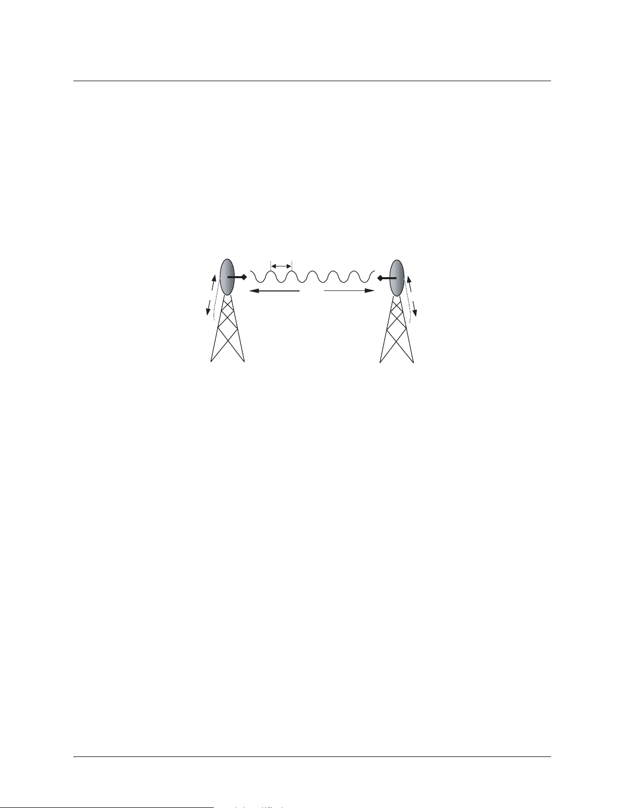
Figure 1 illustrate s a wireless link containing all of the parameter s previously discussed.
λ
G
T
T
d, L
P
G
R
P
R
Figure 1. Example Microwave Path with Parameters
6. ANTENNA ALIGNMENT
With line-of-sight microwave communications, optimum system performance requires that the
transmitting a nd receivi ng a ntennas are proper ly aligne d. This will ensure maxi mum recei ved signal p ower
at each receiver. Antenna alignment must be achieved in both azimuth (along a horizontal plane) and
elevation (along a vertical plane). A received signal strength indicator (RSSI) is used to aid the equipment
installer in deter mining when alignment is maximized, by simply ensuring maximum RSSI. The RSSI
indicator for the TRACER 4206 system is provi ded through the VT100 terminal menus accessed through
the RS-232 inter face, and is present ed as a series of bars indicating signal str ength. More bars means mo re
RSSI, which ensures more received signa l strength and better link performance.
If the local system has acquire d a useful signal from the remote system, then the remote TRACER 4206
RSSI can also be viewed from the local TRACER 4206 VT100 terminal menu interface.
An RSSI T est point is also provided on the front panel. The vol tage (relative to the gnd test point) present
on this test point represe nts a relative signal level of receive stre ngth from the far end. The voltage at this
test point can vary from approxi matly 0 to greater than 4 Volts DC, with 0 Volts corresponding to no signal
and 4 Volts or better to full signal strength.
Antenna Beam Patterns
Directly related to the subject of antenna alignment is the topic of antenna beam patterns. Antennas being
used with the TRACER 4206 system will have a particula r beam shape determined in part by the physical
construction and geometr y of the ant enna. The antenna beam patterns are characterized by a dominant
main lobe, which is the preferred lobe to use for poi nt-to-point communications, and several side lobes, as
612804206L1-1A © 2002 ADTRAN, Inc. 17
Page 18

Section 2, Microwave Path Engineering Basics TRACER 4206 System Manual
shown in Figure 2 on page 18. The antenna alignm ent step to set ting up a microwave link is in f act steer ing
the main lobes of both a ntennas until the main lobe of one transmitter is center ed on the receiving element
of the receiving antenna.
main lobe
side lobes
Figure 2. Typical Antenna Beam Pattern
Antennas are also designed to radiate RF energy efficiently for a specific range of frequencies. Please
consult the data shee t for your parti cular ante nna make and model to ensur e that it is specified to ope rat e in
the 5725 MHz to 5850 MHz frequency band.
Fresnel Zones, Earth Curvature, & Antenna Heights
The Fresnel zones correspond to regions in the microwave path where reflections of the intended signal
occur and combine in both constructive and destructive manners with the main signal, thereby either
enhancing or reducing the net power at the receiver.
In general, the odd numbered Fresnel zo nes (1, 3, 5, ...) add constructively at the receive r, while the even
numbered Fresnel zones (2, 4, 6, ... ) add destructively at the receiver.
The first Fres nel z one corresp onds to the main lobe, and must b e at le ast 60% fr ee of p hysical obstr uctions for
the path calculations to be vali d. Since the main lobe contains the vast majority of the micr owave energ y, this
zone is typically used to determine proper antenna heights when placing antennas on towers or buildings.
The curvature of t he Earth be comes a le git imate obst ructi on for pa th length s of 7 mi les or gr eater, and must
also be accounted for when determining minimum antenna heights.
The aggregate expression f or minimum antenna height that incorporates bot h the 60% first Fresnel zone
and the Earth curvature is given by
h 72.1
d
---- - 0.125d
+=
2
(feet)
4f
where f is in GHz and d is in miles.
Table 3 tabulates minimum antenna heights for given path lengths.
18 © 2002 ADTRAN, Inc. 612804206L1-1A
Page 19

TRACER 4206 System Manual Section 2, Microwave Path Engineering Basics
Table 3. Minimu m An t enna Height for Gi v en P at h Lengths
Path Length
(miles)
2 22
4 32
6 41
8 50
10 60
14 81
16 92
18 104
20 117
22 131
24 145
26 161
28 177
30 194
32 213
34 232
36 252
Min. Antenna Height
(ft)
7. COAXIAL CABLE
Coaxial cable will be re quire d to at tach the TRACER 4206 to t he ant enna. The length of the cabl e will var y
from a few feet to several feet, depending upon your application and the proximity of the TRACER 4206
to the antenna.
Various grades of coaxial cable will work suffic iently well for connecting the TRACER 4206 unit to the
antenna. A low-loss coaxial cable is suggested to minimize cable losses. One end of the cable will require
an N-type male connector (plug) to mate with the TRACER 4206 unit. The other end of the coax will
require a con nector com patible wit h the antenna chose n for the insta llati on, which is usually also a n N-type
male connector (plug). Additionally, it is recommended that both connectors on the coaxial cable be
weatherproofed from the elemen ts to prevent corrosion and electrical shor ting.
T able 3 gives typical loss figures for some of the more common coaxial cable types, per 100 feet.
612804206L1-1A © 2002 ADTRAN, Inc. 19
Page 20

Section 2, Microwave Path Engineering Basics TRACER 4206 System Manual
Table 4. Typical Coaxial Loss for Common Cable Types, per 100 ft
Cable Type Cable Loss (dB/ft)
RG-213, RG-214, RG-293
1/4” Coax
3/8” Coax
1/2” Coax
5/8” Coax
5.8 GHz Elliptical Waveguide
20
11.36
9.65
6.49
4.90
1.23
In certain areas whe r e lightning strikes are frequent, a lightning arre stor should be installed directly on the
antenna coax. This will help protect the RF electronics in the downstream path from damaging voltages
and currents, including the TRACER 4206 unit.
8. RECEIVER SENSITIVITY
Receiver sensitivity is a value expressed in decibels referenced to one milliwatt (dBm) that corresponds to
the minimum amount of signal power needed at the receiver to achieve a given bit error rate (BER).
Receiver sensitivity is usually a negative number of decibels, and as such smaller receiver sensitivity is
better for a given BER. Several fact ors affect receiver sensitivity, including the data bandwidth of the
wireless link, and the amount of additional signal degradation intr oduced in the receiver electronics . The
receiver sensitivity of the TRACER 4206 is -89 dBm at 10
for frequenc y agil ity, should an interfe rer b e ne arby.
-6
bit error rate. Three band plans are provided
9. FADE MARGIN
Fade margin is a val ue indicating the amount of extra si gnal power available to the receiver to operate at a
maximum bit error rat e (BER). Higher levels of fade margin are better, and will protect th e viability of the
microwave link against signa l fading. For most applications, 20 to 30 dB of fade margin should ensure a
reliable link. Fade margin is simply the differenc e between the available signal power at the receiv er and
the receiver sensit ivity, discussed previously:
FPRP
– PRGTGRL– LP– P
sens
–++==
sens
(dB)
10. PATH AVAILABILITY
The path availability of a wireless link is a metric that expresses the fractional amount of time a link is
available over some fixe d a mount of time, and depends on several facto rs. Path availability is expr es sed as
A 12.510
6–
×()abfd310
F 10⁄–
()–[]100%×=
(dB)
20 © 2002 ADTRAN, Inc. 612804206L1-1A
Page 21

TRACER 4206 System Manual Section 2, Microwave Path Engineering Basics
where the parameters are
a terrain factor
b climate factor
f carrier frequency (GHz)
d path length (miles)
F fade margin (dB)
The terrain factor is a quantity that compensates the link availability for different types of terrain.
Generally speaking , the more smooth an area 's terrain is, the less availabil ity a wireless link running
over that terrain will have, primarily due to multipath reflections. In contrast, secondary microwave
signals will be randomly dispe rsed over rough terrain, and will not interfere with the main signal lobe
as badly as in the smooth terrain case. The terrain factor values normally used are listed below:
Terrain Terrain Factor Description
Smooth 4 water, flat desert
Average 1 moderate roughne ss
Mountainous 1/4 very rough, mountainous
The climate factor is a quantity that compensates the link availability for different types of climates
(weather). In general , micr owave links operating in areas with high humidity will have less availability
than those in arid are as , pri ma rily becau s e wat er is a disper siv e me ch an is m t o mic ro wav e en ergy, and
causes the main signal lobe to refract and disperse away from the receiver location. The climate factor
values normally used are liste d be low.
Climate Climate F a ctor Des c r iptio n
Very Dry 1/8 desert regions
Temperate 1/4 mainland, interior region
Humid 1/2 humid and coastal regions
612804206L1-1A © 2002 ADTRAN, Inc. 21
Page 22

Section 2, Microwave Path Engineering Basics TRACER 4206 System Manual
22 © 2002 ADTRAN, Inc. 612804206L1-1A
Page 23

ENGINEERING GUIDELINES
CONTENTS
Equipment Dimensions . . . . . . . . . . . . . . . . . . . . . . . . . . . . . . . . . . . . . . . . . . . . . . . . . . . . . . . . . . 24
Power Requirements . . . . . . . . . . . . . . . . . . . . . . . . . . . . . . . . . . . . . . . . . . . . . . . . . . . . . . . . . . . . 24
Reviewing the Front Panel Design . . . . . . . . . . . . . . . . . . . . . . . . . . . . . . . . . . . . . . . . . . . . . . . . . 24
RSSI Monitoring Interface. . . . . . . . . . . . . . . . . . . . . . . . . . . . . . . . . . . . . . . . . . . . . . . . . . . . . . 24
TX PWR Monitoring Interface . . . . . . . . . . . . . . . . . . . . . . . . . . . . . . . . . . . . . . . . . . . . . . . . . . . 25
Front Panel LEDs . . . . . . . . . . . . . . . . . . . . . . . . . . . . . . . . . . . . . . . . . . . . . . . . . . . . . . . . . . . . 25
Reviewing the TRACER 4206 Rear Panel Design . . . . . . . . . . . . . . . . . . . . . . . . . . . . . . . . . . . . . 26
Antenna Interface . . . . . . . . . . . . . . . . . . . . . . . . . . . . . . . . . . . . . . . . . . . . . . . . . . . . . . . . . . . . 26
Fuse . . . . . . . . . . . . . . . . . . . . . . . . . . . . . . . . . . . . . . . . . . . . . . . . . . . . . . . . . . . . . . . . . . . . . . 26
DC Power Connection. . . . . . . . . . . . . . . . . . . . . . . . . . . . . . . . . . . . . . . . . . . . . . . . . . . . . . . . . 2 7
Alarm Contacts . . . . . . . . . . . . . . . . . . . . . . . . . . . . . . . . . . . . . . . . . . . . . . . . . . . . . . . . . . . . . . 27
T1 Connections. . . . . . . . . . . . . . . . . . . . . . . . . . . . . . . . . . . . . . . . . . . . . . . . . . . . . . . . . . . . . . 27
RS-232 Connection (Terminal Use) . . . . . . . . . . . . . . . . . . . . . . . . . . . . . . . . . . . . . . . . . . . . . . 28
RS-232 Connection (Modem Use) . . . . . . . . . . . . . . . . . . . . . . . . . . . . . . . . . . . . . . . . . . . . . . . 29
At-A-Glance Specifications . . . . . . . . . . . . . . . . . . . . . . . . . . . . . . . . . . . . . . . . . . . . . . . . . . . . . . . 30
FIGURES
Figure 1. TRACE R 4206 Front Panel Layout . . . . . . . . . . . . . . . . . . . . . . . . . . . . . . . . . . . . . . . . 24
Figure 2. TRACE R 4206 Rear Pa nel Layout. . . . . . . . . . . . . . . . . . . . . . . . . . . . . . . . . . . . . . . . . 26
TABLES
Table 1. TRACER 4206 Front Panel Description . . . . . . . . . . . . . . . . . . . . . . . . . . . . . . . . . . . . . 25
Table 2. TRACER 4206 LEDs . . . . . . . . . . . . . . . . . . . . . . . . . . . . . . . . . . . . . . . . . . . . . . . . . . . .25
Table 3. DC Power Connector Pinout . . . . . . . . . . . . . . . . . . . . . . . . . . . . . . . . . . . . . . . . . . . . . . 27
Table 4. Alarm Contact Connector Pinout . . . . . . . . . . . . . . . . . . . . . . . . . . . . . . . . . . . . . . . . . . . 27
Table 5. T1 Interface Connector Pinout . . . . . . . . . . . . . . . . . . . . . . . . . . . . . . . . . . . . . . . . . . . . 27
Table 6. RS-232 Connection Pinout . . . . . . . . . . . . . . . . . . . . . . . . . . . . . . . . . . . . . . . . . . . . . . .28
Table 7. TRACER 4206 (DCE) to Terminal (DTE) Diagram (DB-25) . . . . . . . . . . . . . . . . . . . . . . 28
Table 8. TRACER 4206 (DCE) to Personal Computer (DB-9) . . . . . . . . . . . . . . . . . . . . . . . . . . . 29
Table 9. TRACER 4206 (DCE) to Modem (DCE) . . . . . . . . . . . . . . . . . . . . . . . . . . . . . . . . . . . . . 30
612804206L1-1A © 2002 ADTRAN, Inc. 23
Page 24

Section 3, Engineering Guidelines TRACER 4206 System Manua l
1. EQUIPMENT DIMENSIONS
The TRACER 4206 unit is 19” W, 10.5” D, and 1.75” H, weighs 7 lbs, and can be used in rack-mount
configurations.
2. POWER REQUIREMENTS
The TRACER 4206 system has a maximum power consumption of 25W and a maximum current draw of
1.2A (at 21 VDC).
3. REVIEWING THE FRONT PANEL DESIGN
The front panel contains RSSI and TX PWR monitoring interfaces, a GND interface for reference with the
monitoring interfa ces, and status LEDs to provide visual information about the TRACER 4206 system.
Figure 1 identifies the various bantam interfaces and the LEDs.
Status LEDs
ALARM
TRACER 4206
RSSI
Figure 1. TRACER 4206 Front Panel Layout
T1A T1B T1C T1D
TX PWR
GND
RSSI Monitoring Interface
The RSSI voltage is a function of the signal strength at the receiver and is used to measure the received
signal strength. RSSI varies approximately from 0 to greater than 4 Volts (V), with 0V corresponding to a
weaker received signal and 4V or better corresponding to a stronger received signal.
The voltage level present at the RSSI test point represents only a relative sign al leve l of
receiv e strength from the far end. No direct correlation can be made between RSSI voltage
levels and actual receive levels in dBm. This test point is provide d to assess relative signal
level for alignment of antennas.
24 © 2002 ADTRAN, Inc. 612804206L1-1A
Page 25

TRACER 4206 System Manual Section 3, Engineering Guidelines
TX PWR Monitoring Interface
The TX PWR voltage is a function of the selected tr ansmit power le vel. Thi s voltage ranges appr oximately
from 0 to 5V, with 0V corresponding to +5 dBm (3 milliwatts) and 5V corresponding to +20 dBm (100
milliwatts).
Front Panel LEDs
With the TRACER 4206 powered-on, the front panel LEDs provide visual information about the status of
the TRACER 4206 system. Table 1 provides a brief description of the front panel features, and Table 2
(continued on page 27) provide s detailed information about the LEDs.
Table 1. TRACER 4206 Front Panel Description
Feature Description
RSSI Interface DC voltage indicating strength of the received signal at the antenna
TX PWR Interface DC voltage indicating strength of transmitted signal
GND Interface Ground reference for RSSI and TX PWR interfaces
Status LEDs Provides status information about the system
Table 2. TRACER 4206 LEDs
For these LEDs... Th is co lo r li ght. .. Indicates that...
PWR Green (solid) the TRACER 4206 is connected to a power source.
Off the TRACER 4206 is not currently powered up.
PLAN A Green (solid) the TRACER 4206 is transmitting on Frequency Plan A.
Off the TRACER 4206 is not transmitting on Freque ncy
Plan A.
PLAN B Green (solid) the TRACER 4206 is transmitting on Frequency Plan B.
Off the TRACER 4206 is not transmitting on Freque ncy
Plan B.
RF DOWN Red (solid) there is a communication problem between the local and
remote TRACER 4206 systems.
T1 Alarms
T1A
T1B
T1C
T1D
Red (solid) an Alarm Condition on a T1 Interface. Check the respective
T1 status page to identify the active alarm.
Red (blinking) the respective T1 is in a loopback mode.
612804206L1-1A © 2002 ADTRAN, Inc. 25
Page 26
Section 3, Engineering Guidelines TRACER 4206 System Manua l
Antenna
DC Power
RS232 Interface
Table 2. TRACER 4206 LEDs (Continued)
For these LEDs... This co lor light... Indicates that...
RF LOW Red (solid) the RSSI level is below suggested minimum threshold.
TST Amber (solid) there is an active test being performed by the system or
there is an active loopback.
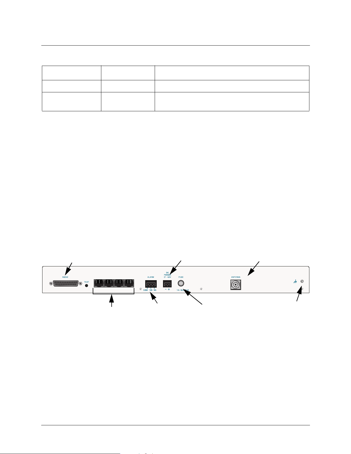
4. REVIEWING THE TRACER 4206 REAR PANEL DESIGN
The TRACER 4206 rear panel contains the followi ng interfaces:
• ALARM interface (terminal block) for connecting to an external alarm monitoring system
DC POWER (terminal block) for connecting to a prope r 21-63 VDC power source
•
T1A, T1B, T1C and T1D (RJ- 48C jacks) for connecting to a T1 device
•
ANTENNA (N-Type connector) for the antenna feedline cable
•
TEST (1/4” stereo jack) for QPSK constellation test point
•
• Ground lug for connecting to earth gr ound
RS-232 (DB-25 female) for connecting to a VT100 terminal or PC with terminal emulation
•
software
Figure 2 on page 26 ide ntifies the various features of the TRACER 4206 rear panel. A detailed discussion
of all interfaces (inc luding pinouts, where applicable) follows the figure.
Antenna Interface
The ANTENNA interface (N-Type connector) connects to the antenna (customer supplied) using standard
antenna feedline cable. When determining the cable specifica tions f or your application, refer to Section 2,
Microwave Path Engineering Basics (Coaxial Cable on page 19) for a discussion on cable length and loss
factors.
Fuse
The fuse holder, accessible from the rear panel of the TRACER 4206, accepts a generic 1 Amp, 250 Volt,
2-inch slow-blo fuse.
(VT100 Terminal)
T1 Interfaces
T1A T1B T1C T1D
Figure 2. TRACER 4206 Rear Panel Layout
Connection
Alarm
Contacts
Fuse
Connector
Ground
Lug
26 © 2002 ADTRAN, Inc. 612804206L1-1A
Page 27

TRACER 4206 System Manual Section 3, Engineering Guidelines
DC Power Connection
The TRACER 4206 can operate from a suppl y between 21 and 63 VDC, with either polarity ref erenced to
ground, and consumes less than 25 Watts (W). Power supplies should be able to provide up to 30 W at
the selected voltag e. Current r equired (in amps) is determined by dividing the power cons umed (in watts)
by the applied voltage (i n volts). For example, at 48 V, TRACER 4206 would draw approximately 0.521 A
(25 W/48 V).
Connec tor t ype Terminal Block
Table 3. DC Power Connector Pinout
PIN NAME DESCRIPTION
1 + POS ITIVE LE AD (referenced to ground)
2 - NEGATIVE LEAD (referenced to ground)
Alarm Contacts
Normally open (NO) and normally closed (NC) alarm conta cts are provided on the rear panel of the
TRACER 4206 system. In normal operation, the NC contact is electrically connected to the common
contact (COM) and the NO contact is isolated. During an alarm condition, the NC contact becomes
isolated and the NO is electri cally connected to COM. This allows alarm conditions to be reported to
external alarm monitoring systems.
Connec tor t ype Terminal Block
Table 4. Alarm Contact Connector Pinout
PIN NAME DESCRIPTION
1 COM COMMON CONTACT
2 NO NO RMALLY-OPEN CONTACT
3 NC NORMALLY-CLOSED CONTACT
T1 Connections
The physical T1 interfaces a re pro vided by 4 RJ-48C jacks that comply with the applicable ANSI and
®
AT&T
Connec tor t ype RJ-48C
standards.
Table 5. T1 Interface Connector Pinout
PIN NAME DESCRIPTION
1 R Transmit data (ring) towards the network
2 T Transmit data (TIP) towards the network
3, 6-8 UNUS ED ——
4 R1 Receive data (ring) toward the network
5 T1 Transmit data (TIP) from the network
612804206L1-1A © 2002 ADTRAN, Inc. 27
Page 28

Section 3, Engineering Guidelines TRACER 4206 System Manua l
RS-232 Connection (Terminal Use)
The RS-232 connector provides a female DB-25 terminal connec tion (wired as a DCE interface), which is
used for terminal access to the TRACER 4206 system. The RS-232 port provides the following functions:
• Accepts EIA-232 input from a PC or terminal for controlling the TRACER 4206 system
• Operates at 9600 bps
Table 6 on page 28 shows the pi nout. W ir ing diagra ms for c onnecting to th e RS-232 connector ( for various
applications) are provided following the pinout.
Connec tor t ype (USOC) DB-25
Table 6. RS-232 Connection Pinout
PIN NAME DESCRIPTION
1, 7 GND GROUND
2TXTRANSMIT
3 RX RECEIVE
4 RTS REQUEST TO SEND
5 CTS CLEAR TO SEND
6 DSR DATA SET READY (MODEM CONTROL ONLY)
8 CD CARRIER DETECT
9-19 — UNUSED
20 DTR DATA TERMINAL READY (MODEM CONTROL ONLY)
21 — UNUSED
22 RI RING INDICATOR
23-25 — UNUSED
Table 7. TRACER 4206 (DCE) to Terminal (DTE) Diagram (DB-25)
PIN NAME PIN NAME
2 TX 2 TX
3 RX 3 RX
4 RTS 4 RTS
5 CTS 5 CT S
6 DSR 6 DSR
7 GND 7 GND
28 © 2002 ADTRAN, Inc. 612804206L1-1A
Page 29
TRACER 4206 System Manual Section 3, Engineering Guidelines
Table 8. TRACER 4206 (DCE) to Personal Computer (DB-9)
PIN NAME PIN NAME
2 TX 2 TX
3 RX 3 RX
4 RTS 7 RTS
5 CTS 8 CT S
6 DSR 6 DSR
7 GND 5 GND
RS-232 Connection (Modem Use)
Modem controls, discussed in Section 5, User Inte rface Guide, of this manual, will enable or disable
modem control through the RS-232 inter face. When this option is enabled from a standard termina l
connection, all RS-232 communications will cease until a modem is attached with a null modem adapter
between the TRACER 4206 and the data modem. The data modem should be configured for AUTO
ANSWER and 9600 bps. When the user connects via modem to the TRACER 4206 unit, communications
via the RS-232 port will resume. If a user acc identa lly enable s modem control from a termina l and disrupts
the RS-232 communication, pr essing <Ctrl + Z> three times will temporaril y disable the modem control
option (until the system is reset) and access the system configuration to disable modem control.
The TRACER 4206 must be interfaced to a modem via an RS-232 null modem adapter or cable. The null
modem will convert Clear To Send (CTS) and Data Set Ready (DSR) into Ready To Send (RTS) and Data
T erminal Ready (DTR), respectiv ely. The se signals will indicate (to most modems) that a valid DTE
terminal device is pr esent. The null mo dem inter face must rout e Carrie r Detec t (CD) on pin 8 di rectly fr om
the modem, and the modem must source CD only wh en actually connected to a carrier when us ing the
RS-232 interface for modem control.
When MODEM CONNECTION (logout) is selecte d in the menu system, the TRACER 4206 will de-ass ert DTR
and DSR for a time greater than 20 ms. The null modem will consequently dr op DTR and RTS at the
modem interface, signaling the modem to hang up the line. If password functionality is enable d in the
TRACER 4206, selecting
MODEM CONNECTION (logout) will rese t the TRACER 4206 to the pa ssword e ntry
screen.
Hangup-on-DTR-drop may need to be explicitly enabled on some modems.
Table 9 on page 30 contains the wiring diagr am needed for connecting the TRACER 4206 RS-232
interface to a modem using the null modem adapter.
612804206L1-1A © 2002 ADTRAN, Inc. 29
Page 30
Section 3, Engineering Guidelines TRACER 4206 System Manua l
Table 9. TRACER 4206 (DCE) to Modem (DCE)
PIN NAME PIN NAME
2 TX 3 RX
3 RX 2 TX
4 RTS 5 CT S
5 CTS 4 RTS
6 DSR 20 DTR
7 GND 7 GND
8 CD 8 CD
5. AT-A-GLANCE SPECIFICATIONS
The following is a list of specifications for the TRACER 4206 system.
Hardware Description Specification
Transmitter
Receiver
Frequency Plan
Output Power +20 dBm, max
Frequency Range 5725 to 5850 MHz
Receive Level, Minimum -8 9dBm
Receive Level, Maximum -3 0 dBm
Receive Level, Nominal -55 dBm
Band Plan
1 Tx 5.734 GHz, Rx 5.814 GHz
Plan A
2 Tx 5.744 GHz, Rx 5.824 GHz
3 Tx 5.753 GHz, Rx 5.833 GHz
30 © 2002 ADTRAN, Inc. 612804206L1-1A
Page 31

TRACER 4206 System Manual Section 3, Engineering Guidelines
Hardware Description Specification
Frequency Plan (continued)
Band Plan
T1 Interface
User Interface
Plan B
1 Tx 5.814 GHz, Rx 5.734 GHz
2 Tx 5.824 GHz, Rx 5.744 GHz
3 Tx 5.833 GHz, Rx 5.753 GHz
Capacity 1.544 Mbps (each)
Connection RJ-48C jacks
Line Code B8ZS, AMI
Framing ESF, D4
Alarms AIS, Red, Yel low, BPVs, LOS
Loopbacks Local and remo te (line and link)
Panel Alarm LEDs
Diagnostics Line and Link Loopbacks
Test Points QPSK Constellation, RSSI, Tx PWR
Alarms Normally Open (NO) and Normally
Closed (NC)
VT100 Terminal Menu Driven User Interface, Control of
the Remote End, Loopback Test,
Optional Password Protection, Event
History
VT100 Terminal Interface
Data Rate 9600 bps
Data B its 8
Parity None
Stop Bits 1
Termi nal Emulation VT100
Mechanical and Environmental
Operating Temperature -25ºC to 65ºC
Size 19” W x 10.5” D x 1.75” H
Humidity 95%, Non-condensing
612804206L1-1A © 2002 ADTRAN, Inc. 31
Page 32

Section 3, Engineering Guidelines TRACER 4206 System Manua l
Hardware Description Specification
Mechanical and Environmental (continued)
Weight 7 lbs
Power
Input Voltage 21 to 63 VDC, either polarity
referenced to ground
Power Consumption <
25 W atts
Connector 2 pin terminal block (DC)
Fuse 1 amp, 250 Volt slow-blo fuse (2-inch)
32 © 2002 ADTRAN, Inc. 612804206L1-1A
Page 33

NETWORK TURNUP PROCEDURE
CONTENTS
Introduction . . . . . . . . . . . . . . . . . . . . . . . . . . . . . . . . . . . . . . . . . . . . . . . . . . . . . . . . . . . . . . . . . . . . 34
Tools Required . . . . . . . . . . . . . . . . . . . . . . . . . . . . . . . . . . . . . . . . . . . . . . . . . . . . . . . . . . . . . . . . . 34
Unpack and Inspect the System . . . . . . . . . . . . . . . . . . . . . . . . . . . . . . . . . . . . . . . . . . . . . . . . . . . 3 4
Contents of ADTRAN Shipment . . . . . . . . . . . . . . . . . . . . . . . . . . . . . . . . . . . . . . . . . . . . . . . . . 34
Customer Provides . . . . . . . . . . . . . . . . . . . . . . . . . . . . . . . . . . . . . . . . . . . . . . . . . . . . . . . . . . . 34
Channel Selection . . . . . . . . . . . . . . . . . . . . . . . . . . . . . . . . . . . . . . . . . . . . . . . . . . . . . . . . . . . . . . 35
Grounding Instructions . . . . . . . . . . . . . . . . . . . . . . . . . . . . . . . . . . . . . . . . . . . . . . . . . . . . . . . . . .35
Supplying Power to the Unit . . . . . . . . . . . . . . . . . . . . . . . . . . . . . . . . . . . . . . . . . . . . . . . . . . . . . . 36
Mounting Options . . . . . . . . . . . . . . . . . . . . . . . . . . . . . . . . . . . . . . . . . . . . . . . . . . . . . . . . . . . . . . . 3 7
Connecting the T1 Interface . . . . . . . . . . . . . . . . . . . . . . . . . . . . . . . . . . . . . . . . . . . . . . . . . . . . . . 37
FIGURES
Figure 1. Bandwidth Division. . . . . . . . . . . . . . . . . . . . . . . . . . . . . . . . . . . . . . . . . . . . . . . . . . . . . 35
612804206L1-1A © 2002 ADTRAN, Inc. 33
Page 34

Section 4, Network Turnup Procedure TRACER 4206 System Manual
1. INTRODUCTION
This section discusses the installation process of the TRACER 4206 system.
Changes or modifications not expressly approved by ADTRAN could void the user’s
authority to operate the equipment.
2. TOOLS REQUIRED
The tools required for the ins tallation of the TRACER 4206 are:
• VT100 terminal or PC with terminal emulation software
• RS-232 (DB-25 male for TRACER 4206 end) cable for connecting to terminal
To prevent electrica l shock, do not inst all equi pment in a wet location or du ring a lightning
storm.
3. UNPACK AND INSPECT THE SYSTEM
Each TRACER 4206 is shipped in its own cardboard shipping carton. Open each carton carefully and
avoid deep penetration into the carton with sharp objects.
After unpacking the unit, inspect it for possible shipping damage. I f the equipment has been damaged in
transit, immed i atel y file a cl ai m wi th the carri er, then cont act A D TRA N Cus tom er Serv i ce (see Customer
Service, Product Support Information, and Training information in the front of this manual).
Contents of ADTRAN Shipment
Your ADTRAN shipment includes the following items:
• TRACER 4206 unit
• TRACER 4206 Documentation CD
• 4 T1 Interconnect Cables (RJ-4 8C Straight-Through)
Customer Provides
The following items are necess ary for the installation of the TRACER 4206 system and are not provided
by ADTRAN:
• 21 to 63 VDC power source (or AC adapter availa ble from ADTRAN P/N 1280650L1), eit her polar ity
referenced to ground
• Antenna and mounting hardware
• Antenna feedline cabl e
34 © 2002 ADTRAN, Inc. 612804206L1-1A
Page 35

TRACER 4206 System Manual Section 4, Network Turnup Pro cedure
z
4. CHANNEL SELECTION
The FCC has allocated 125 MHz of spectrum in the band in which the TRACER 4206 operates. Figur e 1
illustrates the bandwidth division.
Channel A
Band 3Band 2Band 1
57395725 5787 58505749 5758MHz MH
Figure 1. Bandwidth Division
5819 5829 5838
Channel B
Band 3Band 2Band 1
T o designate the utilization of the ISM bandwidth, the re are two differen t channel plans, labeled A and B.
The letter of each channel plan setting is preset by the factory and refers to the physica l configuration of
the diplexer filter inside the environmental housing. Each channel is then divided into three Bandplans (1,
2 or 3). The Bandplans must be the same for the local and remote TRACER 4206. For example, the
transmitter at one end of the lin k will tr ansmit in Bandplan 1 of the lower portion of the spectrum and
receive in Bandplan 1 of the upper portion. Consequently, the receiver at the other end should receive in
Bandplan 1 of the lower portion and transmi t in Bandplan 1 of the upper portion.
The letter of the channel plan (A or B) must be different on both ends and the number of the Bandplan (1,
2, or 3) must be the same on both e nds. Shipmen t of a link will c onsis t of one Plan A, B andplan 2, a nd Plan
B, Bandplan 2, unit.
The channel plan (A or B) of the unit may be changed in the field if necessary by rewiring the internal
diplexer. Contact ADTRAN Technical Support for more information on this procedure.
5. GROUNDING INSTRUCTIONS
The following provides grounding instruction information from the Underwriters’ Laboratory UL 60950
Standard for Safe ty of Information Technology Equipment Including Electrical Business Equipment, of
December, 2000.
An equipment grounding conduct or that is not smaller in size than the ungrounded branch-cir cuit supply
conductors is to be installe d as part of the circuit that supplies the product or system. Bare, covered, or
insulated grounding c onductors are acceptable. Individually covered or insulated equipment grounding
conductors shall have a continuous outer finish that is either green, or green with one or more yellow
stripes. The equipment grounding conductor is to be connected to ground at the service equipment.
The attachment-plug rec ep tacles in the vicinity of the product or system are all to be of a groundi ng type,
612804206L1-1A © 2002 ADTRAN, Inc. 35
Page 36

Section 4, Network Turnup Procedure TRACER 4206 System Manual
and the equipment grounding conduc tors serving these receptacles are to be connected to earth ground at
the service equip ment.
A supplementary equipment grounding conductor shall be installed be tween the product or system and
ground that is in addition to the equipm ent grounding conductor in the power supply cord.
The supplementary equipment gr ounding conductor shall not be smaller in size than the ungr ounded
branch-circuit supply conductors. The supplementary equipment grounding conductor shall be connected
to the product at the terminal pro vide d, a nd shall be connected to ground in a manner that will retain the
ground connection when the produc t is unplugged from the receptacle. The connection to ground of the
supplementary equip ment grounding conductor shall be in compliance with the rule s for terminating
bonding jumpers at Part K or Artic le 250 of the National Electrical Code, ANSI/NFPA 70. Te rmination of
the supplementary equipm ent grounding conductor is permitted to be made to building ste el, to a metal
electrical raceway system, or to any grounded item that is permanently and reliably connected to the
electrical ser vice equipment ground.
The supplemental grounding con ductor sha ll be conne cted to t he equipment using a number 8 ring t erm inal
and should be fastened to the gro unding lug provi ded on the rear panel of th e equipment . The ring termin al
should be installed using the appropriate crimping tool (AMP P/N 59250 T-EAD Crimping Tool or
equivalent.)
The supplemental equipment grounding terminal is located on the rear panel of the
TRACER 4206.
• This unit shall be in stall ed in accorda nce with Arti cle 400 and 364.8 of the N EC NFPA
70 when installed outside of a Restricted Access Locat ion (i.e ., centr al office , behind a
locked door, service personne l only area).
• Power to the TRACER 4206 DC system must be from a reliably grounded 21-63 VDC
source which is electrica lly isolated from the AC source.
• The branch circuit overcur rent protection shall be a fuse or circuit breake r rated minimum 60 VDC, maximum 10A.
• A readily accessible disconne ct device that is suitably approved and rated shall be incorporated in the field wiring.
• Maximum recommended ambient operating te mperature is 45 oC.
6. SUPPLYING PO WER TO THE UNIT
The TRACER 4206 can operate from a suppl y between 21 and 63 VDC, with either polarity ref erenced to
ground. Power supplies should be able to provide up to 30 watts at the selected voltage. A dual pin
terminal plug accepts power at the rear panel of the unit, providing a + and - polarity reference point.
Adapters for this plug are available (P/N 1175043L2) and are furnished with the unit and optional power
supply (P/N 1280650L1).
36 © 2002 ADTRAN, Inc. 612804206L1-1A
Page 37

TRACER 4206 System Manual Section 4, Network Turnup Pro cedure
7. MOUNTING OPTIONS
Install th e TRACER 4206 in a l ocation that requir es minimal antenna feedline length (the loss in this cable
directly aff ects overall system performance) . The TRACER 4206 is design ed to be mounted in a rack. I f
multiple units are insta lled in one location, one half inch of spacing is recommended above and below the
unit.
8. CONNECTING THE T1 INTERFACE
The physical T1 interface is provided using 4 RJ-48C jacks for transmit and receive. Th e provided straight
through T1 interface cable s can be used to inte rface to any standard T1 DTE device.
612804206L1-1A © 2002 ADTRAN, Inc. 37
Page 38

Section 4, Network Turnup Procedure TRACER 4206 System Manual
38 © 2002 ADTRAN, Inc. 612804206L1-1A
Page 39

USER INTERFACE GUIDE
CONTENTS
Navigating the Terminal Menu . . . . . . . . . . . . . . . . . . . . . . . . . . . . . . . . . . . . . . . . . . . . . . . . . . . . 41
Terminal Menu Window . . . . . . . . . . . . . . . . . . . . . . . . . . . . . . . . . . . . . . . . . . . . . . . . . . . . . . . 41
Navigating using the Keyboard Keys . . . . . . . . . . . . . . . . . . . . . . . . . . . . . . . . . . . . . . . . . . . . . 42
Terminal Menu and System Control . . . . . . . . . . . . . . . . . . . . . . . . . . . . . . . . . . . . . . . . . . . . . . . .42
Password Protection. . . . . . . . . . . . . . . . . . . . . . . . . . . . . . . . . . . . . . . . . . . . . . . . . . . . . . . . . . 42
Menu Descriptions . . . . . . . . . . . . . . . . . . . . . . . . . . . . . . . . . . . . . . . . . . . . . . . . . . . . . . . . . . . . . . 43
>TRACER System Status. . . . . . . . . . . . . . . . . . . . . . . . . . . . . . . . . . . . . . . . . . . . . . . . . . . . . . 43
>Main Menu . . . . . . . . . . . . . . . . . . . . . . . . . . . . . . . . . . . . . . . . . . . . . . . . . . . . . . . . . . . . . . . . 45
>TRACER System Configuration . . . . . . . . . . . . . . . . . . . . . . . . . . . . . . . . . . . . . . . . . . . . . . . . 46
>TRACER Link Performance History . . . . . . . . . . . . . . . . . . . . . . . . . . . . . . . . . . . . . . . . . . . . . 48
>T1A Status/Configuration/Loop back . . . . . . . . . . . . . . . . . . . . . . . . . . . . . . . . . . . . . . . . . . . . . 49
>T1A Performance History . . . . . . . . . . . . . . . . . . . . . . . . . . . . . . . . . . . . . . . . . . . . . . . . . . . . . 51
>T1B Status/Configuration/Loop back . . . . . . . . . . . . . . . . . . . . . . . . . . . . . . . . . . . . . . . . . . . . . 52
>T1B Performance History . . . . . . . . . . . . . . . . . . . . . . . . . . . . . . . . . . . . . . . . . . . . . . . . . . . . . 54
>T1C Status/Configuration/Loopback . . . . . . . . . . . . . . . . . . . . . . . . . . . . . . . . . . . . . . . . . . . . . 55
>T1C Performance History . . . . . . . . . . . . . . . . . . . . . . . . . . . . . . . . . . . . . . . . . . . . . . . . . . . . . 57
>T1D Status/Configuration/Loopback . . . . . . . . . . . . . . . . . . . . . . . . . . . . . . . . . . . . . . . . . . . . . 58
>T1D Performance History . . . . . . . . . . . . . . . . . . . . . . . . . . . . . . . . . . . . . . . . . . . . . . . . . . . . . 60
FIGURES
Figure 1. Main Menu Screen. . . . . . . . . . . . . . . . . . . . . . . . . . . . . . . . . . . . . . . . . . . . . . . . . . . . . 41
Figure 2. TRACER System Status . . . . . . . . . . . . . . . . . . . . . . . . . . . . . . . . . . . . . . . . . . . . . . . . 43
Figure 3. Main Menu . . . . . . . . . . . . . . . . . . . . . . . . . . . . . . . . . . . . . . . . . . . . . . . . . . . . . . . . . . . 4 5
Figure 4. TRACER System Configuration. . . . . . . . . . . . . . . . . . . . . . . . . . . . . . . . . . . . . . . . . . . 46
Figure 5. RF Bandplan Band width Division. . . . . . . . . . . . . . . . . . . . . . . . . . . . . . . . . . . . . . . . . . 47
Figure 6. TRACER Link Performance History. . . . . . . . . . . . . . . . . . . . . . . . . . . . . . . . . . . . . . . . 48
Figure 7. T1A Status/Co nfiguration/ Loopback . . . . . . . . . . . . . . . . . . . . . . . . . . . . . . . . . . . . . . . 49
Figure 8. T1A Link Loopba ck . . . . . . . . . . . . . . . . . . . . . . . . . . . . . . . . . . . . . . . . . . . . . . . . . . . . 51
Figure 9. T1A Line Loop back . . . . . . . . . . . . . . . . . . . . . . . . . . . . . . . . . . . . . . . . . . . . . . . . . . . . 51
Figure 10. T1A Link Performance History. . . . . . . . . . . . . . . . . . . . . . . . . . . . . . . . . . . . . . . . . . . . 51
Figure 11. T1B Status/Configuration/Loopback . . . . . . . . . . . . . . . . . . . . . . . . . . . . . . . . . . . . . . . 52
Figure 12. T1B Link Loopback . . . . . . . . . . . . . . . . . . . . . . . . . . . . . . . . . . . . . . . . . . . . . . . . . . . . 53
Figure 13. T1B Line Loopback . . . . . . . . . . . . . . . . . . . . . . . . . . . . . . . . . . . . . . . . . . . . . . . . . . . . 54
Figure 14. T1B Link Performance History. . . . . . . . . . . . . . . . . . . . . . . . . . . . . . . . . . . . . . . . . . . . 54
Figure 15. T1C Status/Configuration/Loop back . . . . . . . . . . . . . . . . . . . . . . . . . . . . . . . . . . . . . . . 55
Figure 16. T1C Link Loopback . . . . . . . . . . . . . . . . . . . . . . . . . . . . . . . . . . . . . . . . . . . . . . . . . . . . 56
Figure 17. T1C Line Loopback . . . . . . . . . . . . . . . . . . . . . . . . . . . . . . . . . . . . . . . . . . . . . . . . . . . . 57
Figure 18. T1C Performance History. . . . . . . . . . . . . . . . . . . . . . . . . . . . . . . . . . . . . . . . . . . . . . . . 57
Figure 19. T1D Status/Configuration/Loop back . . . . . . . . . . . . . . . . . . . . . . . . . . . . . . . . . . . . . . . 58
Figure 20. T1D Link Loopback . . . . . . . . . . . . . . . . . . . . . . . . . . . . . . . . . . . . . . . . . . . . . . . . . . . . 59
Figure 21. T1D Line Loopback . . . . . . . . . . . . . . . . . . . . . . . . . . . . . . . . . . . . . . . . . . . . . . . . . . . . 59
Figure 22. T1D Performance History. . . . . . . . . . . . . . . . . . . . . . . . . . . . . . . . . . . . . . . . . . . . . . . . 60
612804206L1-1A © 2002 ADTRAN, Inc. 39
Page 40

Section 5, User Interface Guide TRACER 4206 System Manual
TABLES
Table 1. T1 Interface Alarms . . . . . . . . . . . . . . . . . . . . . . . . . . . . . . . . . . . . . . . . . . . . . . . . . . . . . 50
40 © 2002 ADTRAN, Inc. 612804206L1-1A
Page 41

TRACER 4206 System Manual Section 5, User Interface Guide
1. NAVIGATING THE TERMINAL MENU
The TRACER 4206 menu system can be accessed with a VT100 compatible terminal set to 9600 bits per
second, 8 data bits, 1 stop bit, and no parity, connected to the RS-232 port located on the back of the unit.
Flow control on the serial inte rface should be configured to None for proper operation. Once a terminal is
connected, pre ssin g <C tr l + L> wil l refres h the curr en t scre en . If pas sw or d acces s has been en abl ed , the
ENTER PASSWORD message will be displayed at the bottom of the TRACER 4206 system status menu.
All TRACER 4206 systems ar e shipped factory default with password prote ction disabled.
Terminal Menu Window
The TRACER 4206 uses 11 (eleven) menu pages and a single main menu page to access its many features.
The main menu page (see Figure 1) provides a link to all available configura tion/status pages.
After connecting a VT100 terminal to the TRACER 4206, press <Ctrl + L> to redraw the
current screen.
Figure 1. Main Menu Screen
612804206L1-1A © 2002 ADTRAN, Inc. 41
Page 42

Section 5, User Interface Guide TRACER 4206 System Manual
Navigating using the Keyboard Keys
You can use various keystrokes to move through the terminal menu, to manage a terminal menu session,
and to configure the system.
Moving through the Menus
To do this... Press this key...
Move up to select items Up Arrow
Move down to select items Down Arrow
Edit a selected menu item Enter
Scroll through configuration parameters for a menu item Spacebar
Left/ Righ t Arrows
P or N (Prev/Next)
Cancel an edit Escape
Return to Main Menu page M
Session Management Keystrokes
To do this... Press this key...
Log into a session Spacebar
Refresh the screen
To sa ve time, only the portion of the screen that has changed is refreshed.
<Ctrl + L>
2. TERMINAL MENU AND SYSTEM CONTROL Password Prot ection
The TRACER 4206 provide s optio nal password pr ot ection of t he termina l interfac e. If enable d, a passwor d
prompt is presented at power-up, reboot, modem logout, or after ten minute s of inactivity on the terminal.
Password protection is enabled and a password is defined via the system configuration menu.
All TRACER 4206 systems ar e shipped factory default with password prote ction disabled.
42 © 2002 ADTRAN, Inc. 612804206L1-1A
Page 43
TRACER 4206 System Manual Section 5, User Interface Guide
3. MENU DESCRIPTIONS
The remainder of this section describes the TRACER 4206 menus and submenus.
The menu structur e of the TRACER 4206 system is depicted below as follows:
> MENU PAGE
> MENU PAGE > MENU SELECTION
> MENU PAGE > MENU SELECTION > SUB-MENU
>TRACER SYSTEM STATUS
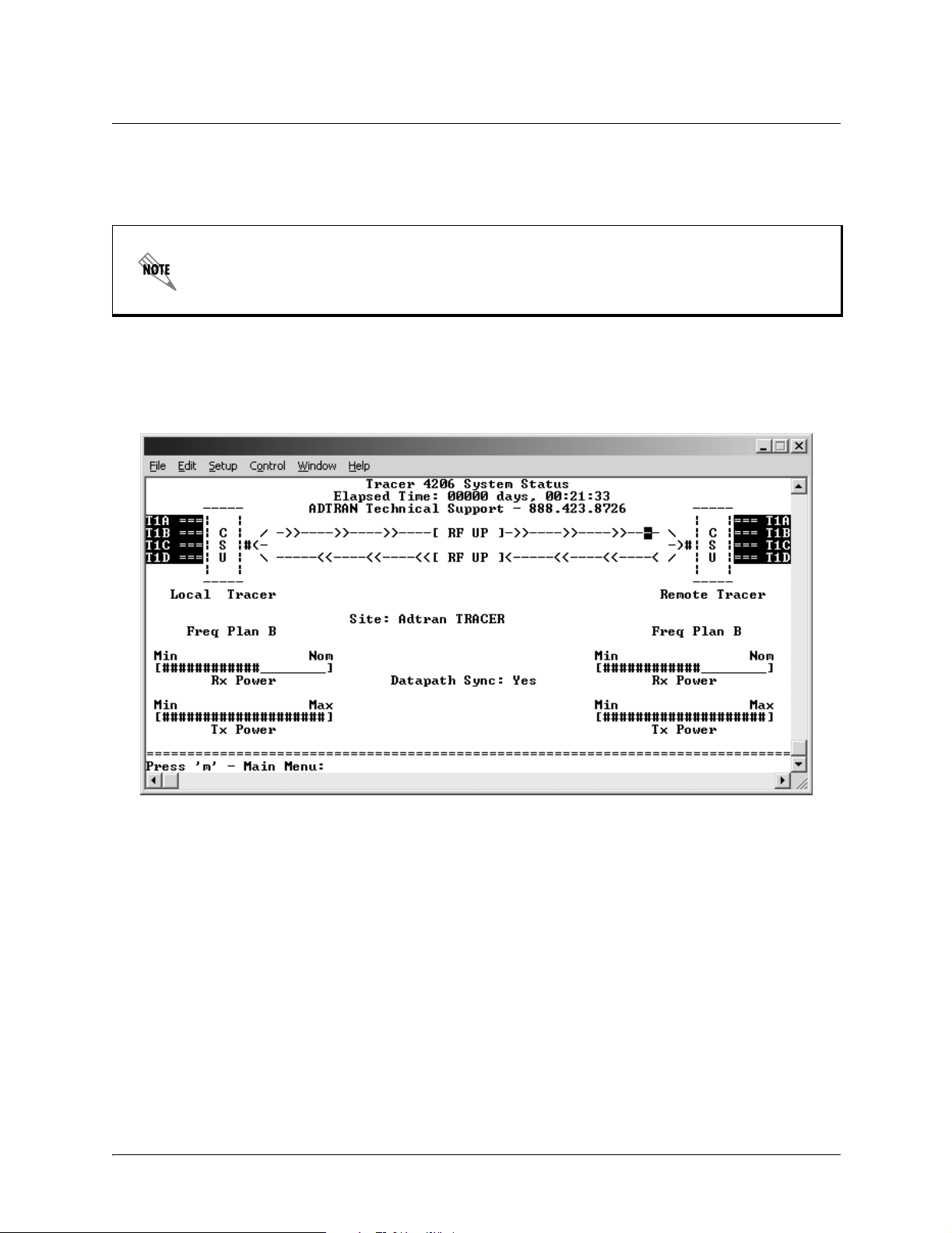
Figure 2 shows the TRACER System S tatus m enu page. S ta tus of majo r system component s fo r both sides
of the TRACER link are displayed, but no configuration can be performed from this view.
Figure 2. TRACER System Status
The top of the TRACER System Status menu page display s the elapsed time the TRACER 4206 system
has been operational sinc e the last power reset. Located directly beneath the ADTRAN Technical Support
phone number is a graphical indic ator of the status of the TRACER 4206 T1 and RF links (as reported by
both the local and remote units). The T1 labels will be reverse highli ghte d if any error conditions exist on
that T1 interface.
The status of the rece ived radio link is indicate d as RF UP or RF DOWN for each direction. The left portion
of the menu page reports the status of the local TRACER 4206 (the system where the active terminal is
attached). The right portion of the screen reports the status of the remot e system. If the RF link is down,
DATA NOT AVAILABLE will be displayed in place of the remote system status.
T o enter the TRACER main menu, press <M>.
612804206L1-1A © 2002 ADTRAN, Inc. 43
Page 44

Section 5, User Interface Guide TRACER 4206 System Manual
Press <0> from any menu in the TRACER 4206 VT100 menu structure to access the
TRACER System Status page.
>TRACER SYSTEM STATUS > FREQUENCY PLAN
Displays the frequency pla n (A or B) for the TRACER 4206 unit. For an operational TRACER 4206
system, the local and remote units should display opposite frequency pla ns.
>TRACER SYSTEM STATUS > SITE
Displays the site name config ured from the TRACER System Configuration page.
>TRACER SYSTEM STATUS > RX POWER
Displays the appr oximate re ceiver le vels ( for both t he local and remote units ) us ing a ser ies of symbols (#).
The more symbols (#) displayed, the stronger the signal. If the link is down and remote end data is
unavailable, DATA NOT AVAILABLE is displayed in place of the symbols (#).
>TRACER SYSTEM STATUS > TX POWER
Displays the approximate transmitter levels (for both the local and remote units) using a series of symbols
(#). The more symbols (#) displayed, the stronger the signal. If the link is down and remote end data is
unavailable,
DATA NOT AVAILABLE is displayed in place of the symbols (#).
44 © 2002 ADTRAN, Inc. 612804206L1-1A
Page 45

TRACER 4206 System Manual Section 5, User Interface Guide
>MAIN MENU
The TRACER 4206 Main Menu page provides access to all other configuration/status pages. Figure 3
shows the TRACER Main Menu page.
Figure 3. Main Menu
Use the up and down arrow keys to scroll through the available pages, or enter the number or letter of the
selected page (to highlight the menu page) and press <Enter>.
Press <M> from any menu in the TRACER 4206 VT100 menu structure to access the
TRACER Main Menu page.
612804206L1-1A © 2002 ADTRAN, Inc. 45
Page 46

Section 5, User Interface Guide TRACER 4206 System Manual
>TRACER SYSTEM CONFIGURATION
Figure 4 shows the TRACER Sy stem Conf iguration m enu page. System conf igura tion para meter s for both
the local and remote TRACER 4206 units are available through this menu page.
Figure 4. TRACER System Configuration
Press <C> from any menu in the TRACER 4206 VT100 menu structure to access the
TRACER System Configuration menu page.
>TRACER SYSTEM CONFIGURATION > RX POWER
Displays the appr oximate re ceiver le vels ( for both t he local and remote units ) us ing a ser ies of symbols (#).
The more symbols (#) displayed, the stronger the signal. If the link is down and remote end data is
unavailable, DATA NOT AVAILABLE is displayed in place of the symbols (#). This parameter is display only.
>TRACER SYSTEM CONFIGURATION > TX POWER
Allows the transmitter levels (for both the local and remote units) to be adjusted. The current transmitter
level is di splayed using a series of symbols (#). The more symbols (#) displayed, the stronger the signal. If
the link is down and remote end data is unavailable, DATA NOT AVAILABLE is displayed in place of the
symbols (#).
Reducing the transmitter power of the remote TRACER 4206 could negatively impact the
TRACER RF link.
46 © 2002 ADTRAN, Inc. 612804206L1-1A
Page 47

TRACER 4206 System Manual Section 5, User Interface Guide
>TRACER SYSTEM CONFIGURATION > SITE NAME
Enter up to 25 alphanumeric characters to be displayed for identification of the TRACER 4206 system.
>TRACER SYSTEM CONFIGURATION > RF BANDPLAN
Sets the bandplan f or the TRACER 42 06. Each c hannel is divide d into four Bandpla ns (1, 2 , 3, or 4) . Both
local and remote TRACER 4206 must be configured with the same bandplan (1, 2, 3, or 4) but different
channel plans (Plan A or Plan B). For example, the transmitter at one end of the link will transmit in
Bandplan 1 of the lower portion of the spectrum and receive in Bandplan 1 of the upper portion.
Consequently, the receiver at the other end should receiv e in Bandplan 1 of the lower portion and transmit
in Bandplan 1 of the upper portion (Refer to Figure 5)
Channel A
Band 3Band 2Band 1
57395725 5787 58505749 5758MHz MHz
Figure 5. RF Ba n dpl a n Ban dwidth Divi si on
5819 5829 5838
Channel B
Band 3Band 2Band 1
>TRACER SYSTEM CONFIGURATION > MODEM CONTROL
Configures the modem control leads on the RS-232 port (termi nal interfa ce located on the rear pa nel of the
unit). Set MODEM CONTROL to ENABLED when connecting the unit to a modem (using a null modem
adapter). Setting MODEM CONTROL to DISABLED prevents the TRACER 4206 from monitoring DCD and
enables data to be sent to the VT 100 continuously. MODEM CONTROL must be set to DISABLED when the
VT100 terminal is in use. The TRACER 4206 comes factory programmed with
DISABLED.
MODEM CONTROL se t t o
Press <Ctrl+Z> three times from the terminal interface to temporarily disable MODEM
ONTROL when the modem control le ads are active.
C
>TRACER SYSTEM CONFIGURATION > MODEM CONNECTION (LOGOUT)
Activator to c ause the TRACER 4206 t o de -assert C lear To Send (CTS) and DSR for a time gr eater tha n 20
milliseconds. This signals the modem to disconnect the analog connection. Hangup-On-DTR-Drop may
need to be explicitly enabled on some modems. If
causes the unit to close the current session and return to the TRACER System Status menu page and wait
for passwor d input .
612804206L1-1A © 2002 ADTRAN, Inc. 47
PASSWORD PROTECTION is ENABLED, this menu also
Page 48

Section 5, User Interface Guide TRACER 4206 System Manual
>TRACER SYSTEM CONFIGURATION > PASSWORD ENABLE
Configures password prote ction for the VT100 terminal interface. Password protection for the TRACER
4206 requires password inpu t from the TRACER System Status menu page when connecting to the unit.
When configured for Password protection, the TRACER 4206 closes any terminal session that remains
inactive for more than 10 minutes. The TRACER 4206 comes factory programmed with
NABLE set to DISABLED.
E
PASSWORD
>TRACER SYSTEM CONFIGURATION > PASSWORD
Sets the password for password protection of the TRACER 4206 VT100 terminal interface. Enter up to 8
alphanumeric chara cter s. The system password is case sensitive.
The default password for the TRACER 4206 is tracer.
>TRACER SYSTEM CONFIGURATION > PERFORMANCE STATS (CLEAR)
Activator to reset all system error counters for the TRACER 4206.
>TRACER LINK PERFORMANCE HISTORY
Figure 6 shows the TRACER Link Performance History menu page. The TRACER Link Performance
History menu page displa ys detailed error stati stics a nd received signal level for the RF link (fr om both the
local and remote TRACER 4206 units) in 15-minute incre ments.
Figure 6. TRACER Link Performance History
48 © 2002 ADTRAN, Inc. 612804206L1-1A
Page 49

TRACER 4206 System Manual Section 5, User Interface Guide
The minimum received signal leve l (MIN RSL) is represented as a numerical value from 0 to 255 with 0
corresponding to no recei ve power and 255 corresponding to an extremely hot signal. The minimum
received signal level is directly related to RSSI.
The error count and received signal level for the most recent 24 hours are recorded and displa yed on the
right side of the page. The left side of the page displays the 24 hour totals for the most recent 7 days.
Press <N> to view the next 8 hours worth of 15-minute totals and <P> to view the
previ ous 8 hours.
Press <L> from any menu in the TRACER 4206 VT100 menu structure to access the
TRACER Link Performance History menu page.
>T1A STATUS/CONFIGURATION/LOOPBACK
Figure 7 shows the T1A Stat us/Configuration/Loopba ck menu page. Real-time graphical representation
for the T1A link (using data from both the local and remote TRACER 4206 units) is displayed on this
page. T1A operational configuration parameters and testing functions are configured from this menu.
Figure 7. T1A Sta t us/Con f iguration/Loopback
Press <1> from any menu in the TRACER 4206 VT100 menu structure to access the
T1A Status/Configuration/Loopback menu page.
612804206L1-1A © 2002 ADTRAN, Inc. 49
Page 50

Section 5, User Interface Guide TRACER 4206 System Manual
>T1A STATUS/CONFIGURATION/LOOPBACK > T1A INTERFACE ALARMS
Displays any active alar ms on the T1A link (reported from both the local and remote TRACER 4206
units). These alarms include Red, Blue, Yellow, AIS, and bipolar violations (BPV). See Secti on 6,
Troubleshooting Guide, for more information on these alarms.
Table 1. T1 Interface Alarms
RED Activates when a local facility failure occurs.
BPV Activates when the incoming T1 stream presents bipolar violations (BPVs).
AIS Activates when an incoming remote alarm is received from a connected T1 device. An AIS
signal is an unframed All One signal that replaces the normal traffic signal
YEL Activates when an incoming remote alarm is received from the T1 device indicating that a
failure has occurred in the received direction.
LOS Activates when no T1 signal is present from the connected T1 equipment. LOS is
activated after receiving 192 consecutive zeros.
>T1A STATUS/CONFIGURATION/LOOPBACK > T1A LINE BUILD OUT
Configures the T1A for the appropria te line buildout, based on the distance to the T1A equipment.
>T1A STATUS/CONFIGURATION/LOOPBACK > ALARM REPORTING
Determines whether the TRACER 4206 unit will report active alarms. If DISABLED, no alarms will be
displayed on this menu page. The ALARM REPORTING parameter is independently configured for the local
and remote TRACER 4206 units. When DISABLED, the front panel LED alarms will also be disabl ed (OFF).
>T1A STATUS/CONFIGURATION/LOOPBACK > SIGNALING
Configures the framing format for the T1A link for both the local and remote TRACER 4206 units. The
TRACER 4206 transports T1A data across the link (as long as the T1A signal is properly timed).
Configure the framing format ( using the SIGNALING menu) to enable the TRACER 4206 to monitor
incoming framing error events and indicate problems with the attached metallic service. The TRACER
4206 supports both
ESF and D4 framing formats.
>T1A STATUS/CONFIGURATION/LOOPBACK > LINE CODE
Sets the line coding for the T1A link. The TRACER 4206 supports B8ZS and AMI line coding.
>T1A STATUS/CONFIGURATION/LOOPBACK > LOOP/NORMAL STATE
Controls the loop status of the T1A link. Act ivates/deactivates loopba ck conditions for testing purposes.
>T1A STATUS/CONFIGURATION/LOOPBACK > LOOP/NORMAL STATE > NORMAL
The T1A link is in normal data transport mode - there are no active loopbacks.
50 © 2002 ADTRAN, Inc. 612804206L1-1A
Page 51

TRACER 4206 System Manual Section 5, User Interface Guide
>T1A STATUS/CONFIGURATION/LOOPBACK > LOOP/NORMAL STATE > LINK
Activates a loopback at the TRACER 4206 T1A framer towards the wireless link (see Figure 8). Use the
LINK loopback to test data path integrity from one unit across the wirele ss link.
Figure 8. T1A Link Loopback
>T1A STATUS/CONFIGURATION/LOOPBACK > LOOP/NORMAL STATE > LINE
Activates a loo pback at th e TRACER 4206 T1A fr amer towards th e locall y con nected T1A equipm ent ( see
Figure 9). Use the LINE loopback to test data path integrity from the TRACER 4206 unit to the T1A
equipment.
Figure 9. T1A Line Loopback
>T1A PERFORMANCE HISTORY
Figure 10 shows the T1A Performance History menu page. The T1A Performance History menu page
displays detaile d error statistics for the T1A link (from both the local and remote TRACER 4206 units) in
15-minute increments.
Figure 10. T1A Li nk Performance History
612804206L1-1A © 2002 ADTRAN, Inc. 51
Page 52

Section 5, User Interface Guide TRACER 4206 System Manual
T1A performance data is presente d as Err ored Seconds (ES) and Severely Errored Seconds (SES) on the
T1A link. The following events qualify as an ES–AIS, LOS or LOF Alarm Second, a single BPV or
excessive zero event, or a single parity bit. An SES is caused by an AIS, LOS or LOF Alarm Second, or
excessive Bi po la r Violations (BPV s) o r fram ed Pari ty Bit errors cau si n g a line Bit Erro r Rat e (B E R) of
-6
10
.
The error count for the most recent 24 hours are reco rded and displayed on the right side of the page. The
left side of the page displays the 24 hour tota ls for the most recent 7 days.
Press <N> to view the next 8 hours worth of 15-minute totals and <P> to view the
previ ous 8 hours.
Press <2> from any menu in the TRACER 4206 VT100 menu structure to access the
T1A Link Performance History menu page.
>T1B STATUS/CONFIGURATION/LOOPBACK
Figure 11 shows the T1B Status/Configuration/Loopback menu page. Real-time graphical representation
for the T1B link ( using da ta f rom bot h t he loc al and r emote TRACER 4206 unit s) is di splaye d o n this pa ge.
T1B operational configur ation parameters and testing functi ons are configured from this menu.
Figure 11. T1B S ta tu s/ C onfigurati on /L oopback
52 © 2002 ADTRAN, Inc. 612804206L1-1A
Page 53

TRACER 4206 System Manual Section 5, User Interface Guide
Press <3> from any menu in the TRACER 4206 VT100 menu structure to access the
T1B Status/Configuration/Loopback menu page.
>T1B STATUS/CONFIGURATION/LOOPBACK > T1B INTERFACE ALARMS
Displays active alarm s on the T1B link reported from both the local and remote TRACER 4206 units.
These alarms include Red, Blue, Yellow, AIS, and bipolar violations (BPV). See Table 1 on page 50 for
more information on these alarms.
>T1B STATUS/CONFIGURATION/LOOPBACK > T1B LINE BUILD OUT
Configures the T1B for the appropriate line buildout, based on the distance to the T1B equipment.
>T1B STATUS/CONFIGURATION/LOOPBACK > ALARM REPORTING
Determines whether the TRACER 4206 unit will report active alarms. If DISABLED, no alarms will be
displayed on this menu page. The Alarm Reporting parameter is independently configur ed for local and
remote TRACER 4206 units. When DISABLED, the front panel LED alarms will also be disabled (off).
>T1B STATUS/CONFIGURATION/LOOPBACK > SIGNALING
Configure the framing format f or the T1B link for both the local and remote TRACER 4206 units. The
TRACER 4206 transports T1B data across the link (as long as the T1B signal is properly timed).
Configure the framing format ( using the SIGNALING menu) to enable the TRACER 4206 to monitor the
incoming framing error events and indicate problems with the attached metallic service. The TRACER
4206 supports both
ESF and D4 framing formats.
>T1B STATUS/CONFIGURATION/LOOPBACK > LINE CODE
Sets the line coding for the T1B link. The TRACER 4206 supports B8ZS and AMI line coding.
>T1B STATUS/CONFIGURATION/LOOPBACK > LOOP/NORMAL STATE
Controls the loop status of the T1B link. Activates/deactivates loopback conditions for testing purposes.
>T1B STATUS/CONFIGURATION/LOOPBACK >LOOP/NORMAL STATE > NORMAL
The T1B link is in normal data transport mode - there are no active loopbacks.
>T1B STATUS/CONFIGURATION/LOOPBACK >LOOP/NORMAL STATE > LINK
Activates a loopback at the TRACER 4206 T1B framer towards the wireless link (see Figur e 12). Use the
LINK loopback to test data path integrity from one unit across the wirele ss link.
Figure 12. T1B Link Loopba c k
612804206L1-1A © 2002 ADTRAN, Inc. 53
Page 54

Section 5, User Interface Guide TRACER 4206 System Manual
>T1B STATUS/CONFIGURATION/LOOPBACK >LOOP/NORMAL STATE > LINE
Activates a loopbac k at the TRACER 4206 T1B framer towards the wireless link (see Figure 13). Use the
LINE loopback to tes t data path integrity from the TRACER 4206 unit to the T1 equipment.
Figure 13. T1B Line Loopba c k
>T1B PERFORMANCE HISTORY
Figure 14 shows the T1B Performance History menu page. The T1B Performance History menu page
displays detaile d error statistics for the T1B link (from both the local an d remote TRACER 4206 units) in
15 minute increments.
Figure 14. T1B Li nk Performance History
T1B performance data is presented as Errored Seconds (ES) and Severely Errored Seconds (SES) on the
T1B link. The following events qualify as an ES–AIS, LOS or LOF Alarm Second, a single BPV or
excessive zero event, or a single parity bit. An SES is caused by an AIS, LOS or LOF Alarm Second, or
excessive Bi po la r Violations (BPV s) o r fram ed Pari ty Bit errors cau si n g a line Bit Erro r Rat e (B E R) of
-6
10
.
The error count for the most recent 24 hours are recorded and displaye d on the right side of the page. The
54 © 2002 ADTRAN, Inc. 612804206L1-1A
Page 55

TRACER 4206 System Manual Section 5, User Interface Guide
left side of the page displays the 24 hour tota ls for the most recent 7 days.
Press <N> to view the next 8 hours worth of 15 minute totals and <P> to view the
previ ous 8 hours.
Press <4> from any menu in the TRACER 4206 VT100 menu structure to access the T1B
Link Performance History page.
>T1C STATUS/CONFIGURATION/LOOPBACK
Figure 15 shows the T1C Status/Configuration/Loop back menu page. Real-time graphical representation
for the T1C link usi ng data from bot h the loc al and remot e TRACER 4206 unit s) is disp layed on this page.
T1C operational configur ation parameters and testing functi ons are configured from this menu.
Figure 15. T1C S ta tu s/ C onfigurati on /L oopback
Press <5> from any menu in the TRACER 4206 VT100 menu structure to access the T1C
Status /Configuration/Loopbac k menu page.
612804206L1-1A © 2002 ADTRAN, Inc. 55
Page 56

Section 5, User Interface Guide TRACER 4206 System Manual
>T1C STATUS/CONFIGURATION/LOOPBACK > T1C INTERFACE ALARMS
Displays and ac tive alarms on the T1C link reported from both the local and remote TRACER 4206 units.
These alarms include Red, Blue, Yellow, AIS, and bipolar violations (BPV). See Table 1 on page 50, for
more information on these alarms.
>T1C STATUS/CONFIGURATION/LOOPBACK > T1C LINE BUILD OUT
Configures the T1C for the appropriate line buildout, based on the distance to the T1C equipment.
>T1C STATUS/CONFIGURATION/LOOPBACK > ALARM REPORTING
Determines whether the TRACER 4206 unit will report active alarms. If DISABLED, no alarms will be
displayed on this menu page. The Alarm Reporting parameter is independently configur ed for local and
remote TRACER 4206 units. When
DISABLED, the front panel LED alarms will also be disabled (off).
>T1C STATUS/CONFIGURATION/LOOPBACK > SIGNALING
Configure the framing format f or the T1C link for both the local and remote TRACER 4206 units. The
TRACER 4206 transports T1C data across the link (as long as the T1C signal is properly timed).
Configure the framing format ( using the SIGNALING menu) to enable the TRACER 4206 to monitor the
incoming framing error events and indicate problems with the attached metallic service. The TRACER
4206 supports both
ESF and D4 framing formats.
>T1C STATUS/CONFIGURATION/LOOPBACK > LINE CODE
Sets the line coding for the T1C link. The TRACER 4206 supports B8ZS and AMI line coding.
>T1C STATUS/CONFIGURATION/LOOPBACK > LOOP/NORMAL STATE
Controls the loop status of the T1C link. Activates/deactivates loopback conditions for testing purposes.
>T1C STATUS/CONFIGURATION/LOOPBACK > LOOP/NORMAL STATE > NORMAL
The T1C link is in normal data transport mode - there are no active loopbacks.
>T1C STATUS/CONFIGURATION/LOOPBACK > LOOP/NORMAL STATE > LINK
Activates a loopback at the TRACER 4206 T1C framer towards the wireless link (see Figur e 17). Use the
LINK loopback to test data path integrity from one unit across the wirele ss link.
Figure 16. T1C Link Loopba c k
56 © 2002 ADTRAN, Inc. 612804206L1-1A
Page 57

TRACER 4206 System Manual Section 5, User Interface Guide
>T1C STATUS/CONFIGURATION/LOOPBACK > LOOP/NORMAL STATE > LINE
Activates a loopback at the TRACER 4206 T1C framer towards the wireless link (see Figur e 17). Use the
LINE loopback to test data path integrity from the TRACER 4206 unit to the T1 equipment.
Figure 17. T1C Line Loopba c k
>T1C PERFORMANCE HISTORY
Figure 18 shows the T1C Performance History menu page. The T1C Performance History menu page
displays detaile d error statistics for the T1C link (from both the local an d remote TRACER 4206 units) in
15 minute increments.
Figure 18. T1C Pe rformance Hist ory
T1C performance data is presented as Errored Seconds (ES) and Severely Errored Seconds (SES) on the
T1C link. The following events qualify as an ES–AIS, LOS or LOF Alarm Second, a single BPV or
excessive zero event, or a single parity bit. An SES is caused by an AIS, LOS or LOF Alarm Second, or
excessive Bi po la r Violations (BPV s) o r fram ed Pari ty Bit errors cau si n g a line Bit Erro r Rat e (B E R) of
-6
10
.
The error count for the most recent 24 hours are recorded and displaye d on the right side of the page. The
left side of the page displays the 24 hour tota ls for the most recent 7 days.
612804206L1-1A © 2002 ADTRAN, Inc. 57
Page 58
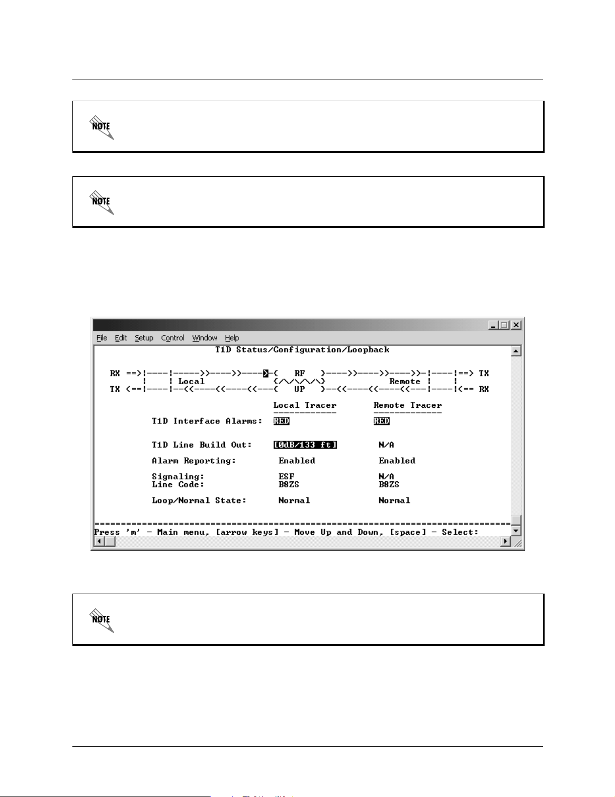
Section 5, User Interface Guide TRACER 4206 System Manual
Press <N> to view the next 8 hours worth of 15 minute totals and <P> to view the
previ ous 8 hours.
Press <6> from any menu in the TRACER 4206 VT100 menu structure to access the T1C
Link Performance History page.
>T1D STATUS/CONFIGURATION/LOOPBACK
Figure 19 shows the T1D Status/Configuration/Loopback menu page. Real-time graphical representation
for the T1D link (using data from both the local and remote TRACER 4206 units) is displayed on this
page. T1D operational configuration parameters and testing functions are configured from this menu.
Figure 19. T1D S ta tu s/ C onfigurati on /L oopback
Press <7> from any menu in the TRACER 4206 VT100 menu structure to access the T1D
Status/Configuration/Loopback menu page.
>T1D STATUS/CONFIGURATION/LOOPBACK > T1D INTERFACE ALARMS
Displays and active alarms on the T1D link reported from both the local and remote TR ACER 4206 units.
These alarms include Red, Blue, Yellow, AIS, and bipolar violations (BPV). See Table 1 on page 50, for
more information on these alarms.
58 © 2002 ADTRAN, Inc. 612804206L1-1A
Page 59
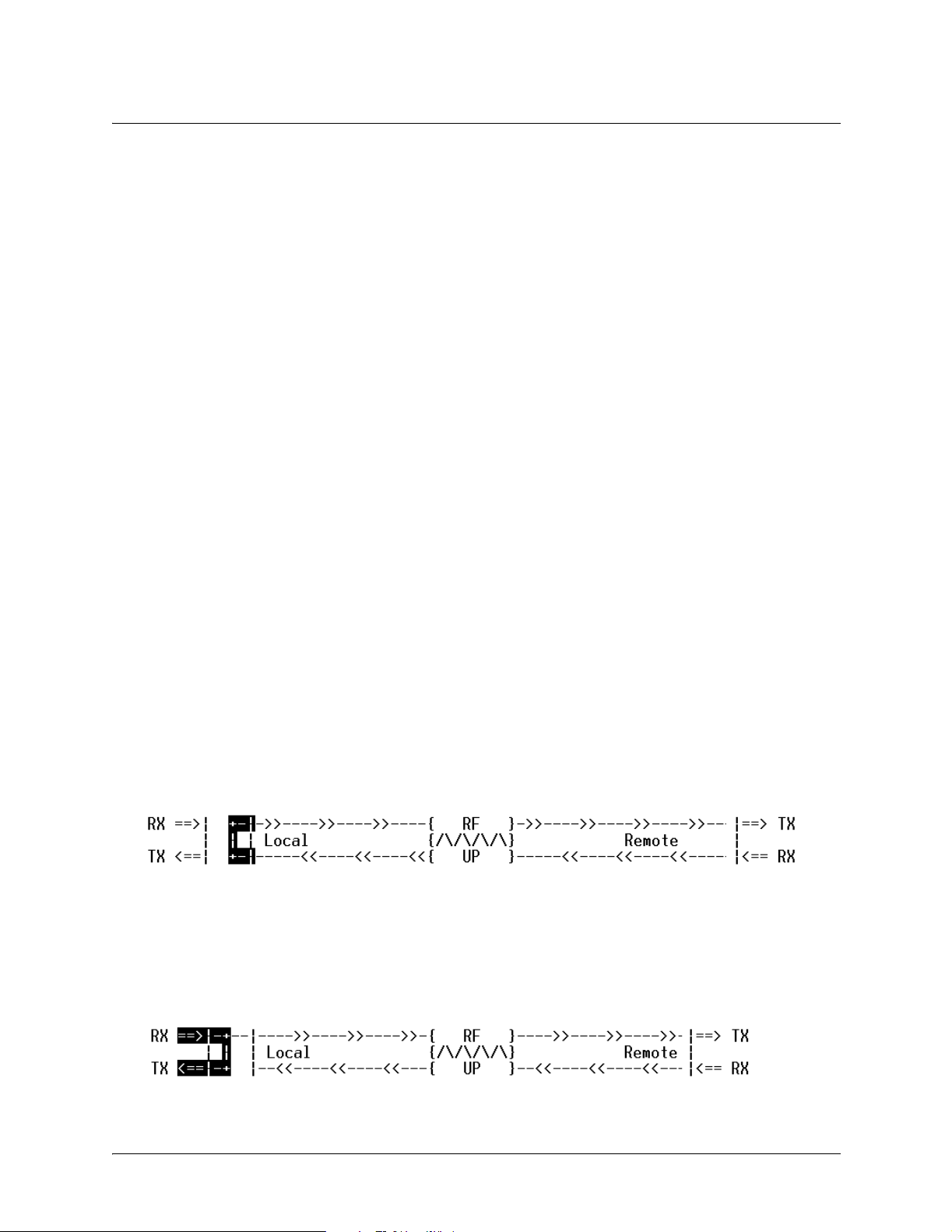
TRACER 4206 System Manual Section 5, User Interface Guide
>T1D STATUS/CONFIGURATION/LOOPBACK > T1D LINE BUILD OUT
Configures the T1D for the appropria te line buildout, based on the distance to the T1D equipment.
>T1D STATUS/CONFIGURATION/LOOPBACK > ALARM REPORTING
Determines whether the TRACER 4206 unit will report active alarms. If DISABLED, no alarms will be
displayed on this menu page. The Alarm Reporting parameter is independently configur ed for local and
remote TRACER 4206 units. When
DISABLED, the front panel LED alarms will also be disabled (off).
>T1D STATUS/CONFIGURATION/LOOPBACK > SIGNALING
Configure the framing format f or the T1D link for both the local and remote TRACER 4206 units. The
TRACER 4206 transports T1D data across the link (as long as the T1D signal is properly timed).
Configure the framing format ( using the
SIGNALING menu) to enable the TRACER 4206 to monitor the
incoming framing error events and indicate problems with the attached metallic service. The TRACER
4206 supports both ESF and D4 framin g for ma ts.
>T1D STATUS/CONFIGURATION/LOOPBACK > LINE CODE
Sets the line coding for the T1D link. The TRACER 4206 supports B8ZS and AMI line coding.
>T1D STATUS/CONFIGURATION/LOOPBACK > LOOP/NORMAL STATE
Controls the loop status of the T1D link. Activ ates/deactivates loopback cond itions for testing purposes.
>T1D STATUS/CONFIGURATION/LOOPBACK > LOOP/NORMAL STATE > NORMAL
The T1D link is in normal data transport mode - there are no active loopbacks.
>T1D STATUS/CONFIGURATION/LOOPBACK > LOOP/NORMAL STATE > LINK
Activates a loopback at the TRACER 4206 T1D f ramer towards the wireless link (see Figure 20). Use th e
LINK loopback to test data path integrity from one unit across the wirele ss link.
Figure 20. T1D Link Loopba c k
>T1D STATUS/CONFIGURATION/LOOPBACK > LOOP/NORMAL STATE > LINE
Activates a loopback at the TRACER 4206 T1D f ramer towards the wireless link (see Figure 21). Use th e
LINE loopback to tes t data path integrity from the TRACER 4206 unit to the T1 equipment.
Figure 21. T1D Line Loopba c k
612804206L1-1A © 2002 ADTRAN, Inc. 59
Page 60
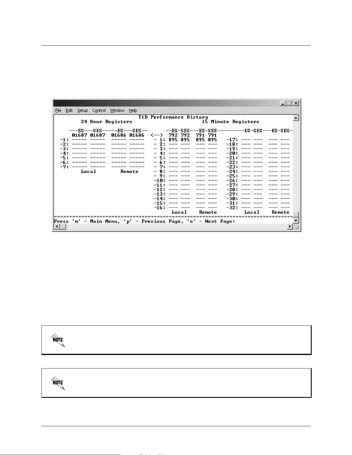
Section 5, User Interface Guide TRACER 4206 System Manual
>T1D PERFORMANCE HISTORY
Figure 22 shows the T1D Performanc e History menu page. The T1D Performance History menu page
displays detaile d error statistics for the T1D link (from both the local and remote TRACER 4206 units) in
15 minute increments.
Figure 22. T1D Pe rformance Hist ory
T1D performance data is presente d as Err ored Seconds (ES) and Severely Errored Seconds (SES) on the
T1D link. The following events qualify as an ES–AIS, LOS or LOF Alarm Second, a single BPV or
excessive zero event, or a single parity bit. An SES is caused by an AIS, LOS or LOF Alarm Second, or
excessive Bi po la r Violations (BPV s) o r fram ed Pari ty Bit errors cau si n g a line Bit Erro r Rat e (B E R) of
-6
10
.
The error count for the most recent 24 hours are recorded and displaye d on the right side of the page. The
left side of the page displays the 24 hour tota ls for the most recent 7 days.
Press <N> to view the next 8 hours worth of 15 minute totals and <P> to view the
previ ous 8 hours.
Press <8> from any menu in the TRACER 4206 VT100 menu structure to access the T1D
Link Performance History page.
60 © 2002 ADTRAN, Inc. 612804206L1-1A
Page 61

TROUBLESHOOTING GUIDE
CONTENTS
Overview. . . . . . . . . . . . . . . . . . . . . . . . . . . . . . . . . . . . . . . . . . . . . . . . . . . . . . . . . . . . . . . . . . . . . . . 6 2
LED Indicators. . . . . . . . . . . . . . . . . . . . . . . . . . . . . . . . . . . . . . . . . . . . . . . . . . . . . . . . . . . . . . . . . . 62
PWR LED . . . . . . . . . . . . . . . . . . . . . . . . . . . . . . . . . . . . . . . . . . . . . . . . . . . . . . . . . . . . . . . . . . .62
TST LED. . . . . . . . . . . . . . . . . . . . . . . . . . . . . . . . . . . . . . . . . . . . . . . . . . . . . . . . . . . . . . . . . . . .62
RF DOWN LED . . . . . . . . . . . . . . . . . . . . . . . . . . . . . . . . . . . . . . . . . . . . . . . . . . . . . . . . . . . . . . .62
RF LOW LED . . . . . . . . . . . . . . . . . . . . . . . . . . . . . . . . . . . . . . . . . . . . . . . . . . . . . . . . . . . . . . . .63
T1 Alarm LEDs . . . . . . . . . . . . . . . . . . . . . . . . . . . . . . . . . . . . . . . . . . . . . . . . . . . . . . . . . . . . . . .63
RF Errors . . . . . . . . . . . . . . . . . . . . . . . . . . . . . . . . . . . . . . . . . . . . . . . . . . . . . . . . . . . . . . . . . . . . . . 64
Step-by-Step Troubleshooting. . . . . . . . . . . . . . . . . . . . . . . . . . . . . . . . . . . . . . . . . . . . . . . . . . . . . 6 4
Installing/Troubleshootin g the TRACER Hardware . . . . . . . . . . . . . . . . . . . . . . . . . . . . . . . . . . . . 64
Installing/Configuring T1 Hardware. . . . . . . . . . . . . . . . . . . . . . . . . . . . . . . . . . . . . . . . . . . . . . . .66
612804206L1-1A © 2002 ADTRAN, Inc. 61
Page 62

Section 6, Troubleshooting Guide TRACER 4206 System Manual
1. OVERVIEW
This troubleshooting guide provides recommended actions for various conditions of the TRACER 4206
system. The status LEDs (located on the front panel of the unit) provide information to help determine the
necessary troubleshooting action. Recommended actions for resolving possible status LED indicators are
contained in this guide.
2. LED INDICATORS
PWR LED
If the PWR LED is not ON and solid green, it is an indicator that the TRACER 4206 is not receiving
adequate DC power.
Recommended Actions:
1. Verify that the power source is delivering between 21 and 63 VDC.
2. Check the polarity of the power connection (referenced to ground) of both the TRACER 4206 unit and
the power source.
3. Check the internal fuse. The fuse is accessed from the rear panel of the unit. If this fuse is open,
replace with a 1Amp, 250 Volt (2-inch) slow-blo fuse.
TST LED
The TST will remain ON (solid Amber) during power-up to indicate a self-test is in progress. If the TST
LED is blinking or remains ON after 10 seconds, this indicates that the TRACER 4206 unit has failed
self-test. This is an internal failure, and ADTRAN technical support should be contacted.
RF DOWN LED
If the RF DOWN LED is ON (solid Red), it is an indicator that there is a problem with the RF link to the
TRACER 4206.
Recommended Actions:
1. Check the RF coaxial cable connection.
2. Measure the RSSI voltage. If the signal is acceptable (> 2.0 VDC at RSSI test point), go to Step 6.
3. Verify that one end of the link is configured as Plan A and the other end is Plan B and that both ends
have the same Band Plan Number (ex. A1 and B1).
4. Verify that the antenna polarization is the same at both ends of the RF signal transmit and receive
path.
5. Verify the RF signal path is clear.
6. Check for possible interference at both ends of the link. If necessary, change polarization and/or Band
Plans at both ends.
62 © 2002 ADTRAN, Inc. 612804206L1-1A
Page 63

TRACER 4206 System Manual Section 6, Troubleshoot ing Guide
RF LOW LED
If the RF LOW LED is ON (solid Red), it is an indicator that the received signal is within 10 dB
(approximately ) of the minimum opera ble signal. This condition is typically indicative of a path problem.
Recommended Actions:
1. Verify the far-end transmitter power setting is the value that the link planning budget allows.
2. Check all coaxial cable connectors for solid connections. Check for water and corrosion around any of
the connectors. If water is apparent in the coax connectors, replace the coax.
3. Verify the RF signal path by verifying the antenna alignment.
4. Check the integrity of the cable plant.
5. Check the integrity of lightning arrestors.
T1 Alarm LEDs
If the ALARM LED is ON ( solid red), it is an indication that the TRACER 4206 is detect ing an act ive T1
alarm. To identify the T1 interface in alarm and the specific alarm present, display the T1 (x) Status
Screens and check the T1(X) INT ERFACE ALARMS field.
Recommended Actions:
1. Display the T1(X) St atus Screen and Check the T1(X) Interface Alarm field to identify the active alarm.
2. Follow the steps below for the appropriate alarm.
LOS Alarm (Red Alarm)
LOS ALARM is an indication that the TRACER 4206 may be unable to detect a viable T1 received
signal from the co nnected T1 equipment. This error may be due to a degraded signal or no signal, or is
may be caused by improper framing.
Recommended Actions:
1. Verify that the T1 cable is connected to the T1 interface on the TRACER 4206.
2. Verify the connections at the opposite end of the T1 cable.
3. Verify that the framing mode (D4 or ESF) is the same for both the TRACER 4206 and the T1
equipment.
Yellow Alarm
A Yellow Alarm is generated by the attached equipment. Whe n the attached equipment’s T1 interface
is in Red Alarm, a Yellow Alarm will be generated at the TRACER 4206 unit.
Recommended Actions:
1. Follow the troubleshooting steps for Red Alarm, but do so at the attached equipment.
612804206L1-1A © 2002 ADTRAN, Inc. 63
Page 64

Section 6, Troubleshooting Guide TRACER 4206 System Manual
Blue Alarm
A remote alarm (alarm indication signal or AIS) is generated by the attached equipment. The root
cause must be determined at the attached equipment. A typical cause of a blue alarm is a lack of input
to a CSU.
Recommended Actions:
1. Verify the input to any attached data equipment.
BPV
Bipolar violati ons (BPVs) indicate an improper configuration or faulty wiring.
Recommended Actions:
1. Veri fy the TRACER 4206 unit and the attached equipment are configured for the same line coding
(B8ZS or AMI).
2. Verify the cable connections for the T1 interface are solid.
3. RF ERRORS
RF errors can range anywhere from a non-viable microwave path to loose RF connectors.
Non-viable path conditions c ould be caused by physical obstructions suc h as buildings, moutainous terra in,
trees, etc., as well as other physical limitations such as excessive path distances and in-band RF
interference . The se types of errors are remedied by performing a detaile d line-of-sight microwave path
study to determine whether or not a microwave link is feasible for the terrain and environment unde r
consideration.
If after performing a microwave path study the system is still not operational, ensure that the antennas are
properly aligned. Note that alignment must be achieved in both elevation and azimuth for optimal link
performance. The TRACER 4206 can be used to aid in antenna alignment by looking at the RSSI
submenu. Optimal antenna alignment will correspond to the maximum number of RSSI bars on the
TRACER 4206 terminal display.
4. STEP-BY-STEP TROUBLESHOOTING
The logical troubleshooting flow presented in this section can be used to set up your TRACER 4206
system, and also to dia gno se a pr ev io usl y ins tal le d system. Please co nta ct ADTR A N Technical suppor t at
any stage during installation and/or troubleshooting if you require assistance.
5. INSTALLING/TROUBLESHOOTING THE TRACER HARDWARE
1. Perform a detailed path profile for each TRACER 4206 microwave link. A thorough path study can
be used to estimate signal power budgets, fade margins at each receiver, identity potential
line-of-site obstacles, properly size antenna dishes, and determine minimum antenna dish heights
above the earth.
2. Setup all of the TRACER hardware on a work bench. It is also recommended that the actual
cables to be used in the permanent installation be used in the work bench setup. A rigorous work
bench “simulation” of the link will help you alleviate and avoid time-consuming errors.
64 © 2002 ADTRAN, Inc. 612804206L1-1A
Page 65

TRACER 4206 System Manual Section 6, Troubleshoot ing Guide
3. Examine the PLAN A and PLAN B lights on the front panel of each unit. These LEDs indicate the
frequency plan for each TRACER 4206 unit. The frequency plan (PLAN A, PLAN B) LED should
be the opposite on both TRACER 4206 units.
4. Attach the RF coaxial cables to be used in the permanent installation to the N-type connectors on
the base of the TRACER 4206 unit. Attach the other end of the coaxial cable(s) to an RF power
meter or spectrum analyzer if either is available. The power measured by the met er/ analy z er w ill
be the RF power available at the input of the antenna. The TRACER 4206 unit is programmed at
the factory to output approximately 100 mW (20 dBm) of 5.8 GHz RF power. The actual power
level measured by the meter/analyzer will be less than 100 mW due to RF losses through the
coaxial cable, and is a function of cable type and length of cable being used. In any event, the
power level at the output of the coaxial cable should be a significant fraction of 100 mW. A power
meter/analyzer reading that is not on the order of at least tens-of - m illiwatts could be an indication
of any combination of either unsuitable RF, faulty, or unreasonably long coaxial cable.
5. Resolve all RF coaxial cabling errors before proceeding.
6. Attach the RF coaxial cables to a 5.8 GHz attenuator, if possible. If you do not have an attenuator,
attach the coaxial cables to the antennas to be used in the permanent installation. If the installation
antennas are not available, small, inexpensive dipole or patch antennas can be used for
verification purposes. If an adjustable attenuator is being used, dial in the amount of attenuation
that corresponds to the path loss value expected for the microwave link in which the TRACER
hardware will be installed. The path loss value can be calculated from a knowledge of the path
length, or provided by a path study. Remember to subtract both antenna gain values from the
attenuator level if these values have not already be accounted for.
7. After setting up the RF pieces, examine the RF DOWN LED on the front panel of each TRACER
4206 unit. If the RF DOWN LED is illuminated (red), the corresponding TRACER 4206 is not
receiving a suitable RF signal from the other TRACER 4206 unit. In this case, the receiving
TRACER 4206 is either receiving a very weak signal, or no signal at all. If the RF DOWN LED is
not illuminated, then the TRACER 4206 units are receiving a suitable RF signal. Suitable RF
power levels for low error rate communication will range from -30 dBm to -92 dBm measured at the
N-type connector input on the TRACER 4206 unit.
8. Resolve any signal level issues before proceeding.
9. Examine the RF LOW LED on the front panel of each TRACER 4206. If this LED is illuminated,
then the TRACER 4206 is receiving a relatively weak signal, however if the RF DOWN LED is not
illuminated, the received signal is being suitably processed by the TRACER system. If you are
receiving a weak signal (RF LOW is ON), please verif y that the weak signal is not being caused by
a faulty cable, an insufficiently tightened cable, or some other installation-related problem. Also,
make sure an unreasonably large attenuation value has not been selected if you are using an
attenuator on a work bench setup.
Use the tables in Section 2, Microwave Path Engineering Basics, of this manual to select the
proper free-space attenuation value (in dB) based on the estimated length of the microwave path.
Remember to subtract out both antenna gains (local and remote) from the attenuator setting.
10. Command a link loopback in one TRACER 4206 unit and run pattern from the connected T1
equipment. This will v er if y data path between the T1 equipment and the TRACER 4206 unit.
External pattern generators are required to test data path integrity. A T1 BERT tester is
suggested.
612804206L1-1A © 2002 ADTRAN, Inc. 65
Page 66

Section 6, Troubleshooting Guide TRACER 4206 System Manual
Installing/Configuring T1 Hardware
1. If possible, attach any or all of the intended T1 hardware to the TRACER 4206 units using the
same work bench setup. This step offers the perfect opportunity to configure your T1 hardware for
proper functioning with the TRACER hardware.
2. Resolve any remaining T1 equipment-to-TRACER 4206 c onfiguration issues before field
installation, if possible. This will s igni fican tly r educe the probability of unsuccess ful field
installation.
66 © 2002 ADTRAN, Inc. 612804206L1-1A
 Loading...