

Page 1

TRACER 4205
System Manual
12804205L1A TRACER 4205 System (Plan A)
12804205L1B TRACER 4205 System (Plan B)
612804205L1-1A
August 2002
Page 2

Trademarks
Any brand names and product names included in this manua l are trademarks, registered trademarks, or
trade names of their respective holders.
To the Holder of the Manual
The contents of t his manual are curre nt as of the date of publi catio n. ADTRAN reser ves the right t o change
the contents without pri or notice.
In no event will ADTRAN be liable for any special, incidental, or consequential damages or for
commercial losses even if ADTRAN has been advised thereof as a result of issue of this publication.
901 Explorer Boulevard
P.O. Box 140000
Huntsville, AL 35814-4000
Phone: (256) 963-8000
©2002 ADTRAN, Inc.
All Rights Reserved.
Printed in U.S.A.
Page 3

About this Manual
This manual provides a complete description of the TRACER 4205 system and system software.
The purpose of this manual is to provide the technician, system administrato r, and manager with
general and specific inf ormation related to the planning, insta llation, operation, and maintenance of the
TRACER 4205. This manual is arranged so that needed information can be quickly and easily found. The
following is an overview of the cont ents.
Section 1 4205 System Description
Provides managers with an overview of the TRACER 4205 system.
Section 2 Microwave Path Engineering Basics
Explains the basics of analyz ing a wireless microwave link, or path. The significant
parameters are defin ed, and several recommendations are offered.
Section 3 Engineering Guidelines
Provides information to a ssist network designers with incor porating the
TRACER 4205 system into their networks.
Section 4 Network Turnup Procedure
Provides step-by- step in struc tions on how to in sta ll the TRACER 4205 unit , dete rmin e the
parameters for the syst em, install the network and option modules, and power up the
system.
Section 5 User Interface Guide
Explains the termina l interface and provides a description for each of the menus availabl e
for the TRACER 4205 system.
Section 6 Troubleshooting Guide
Provides helpful inf ormation for troubleshooting common config uration problems for the
TRACER 4205 system.
Revision History
This is the first issue of this manual.
612804205L1-1A © 2002 ADTRAN, Inc. 3
Page 4
Notes provide additional useful informat ion.
Cautions signify information that could prevent service interruption.
Warnings provide information that could prevent damage to the equipment or
endangerment to human life.
Safety Instructions
When using your telephone equipment , please follow these basic safety precautions to reduce the risk of
fire, electrical shock, or personal injury:
1. Do not use this product near water, such as a bathtub, wash bowl, kitchen sink, laundry tub, in a
wet basement, or near a swimming pool.
2. Avoid using a telephone (other than a cordless-type) during an electrical storm. There is a remote
risk of shock from lightning.
3. Do not use the telephone to report a gas leak in the vicinity of the leak.
4. Use only the power cord , power supply, an d/or ba tteries indicate d in the manua l. Do not disp ose of
batteries in a fire. They may explode . Chec k with local codes for special disposal instructions.
Save These Important Safety Instructions
4 © 2002 ADTRAN, Inc. 612804205L1-1A
Page 5
Federal Communications Commission Radio Frequency Interference Statement
This equipment has been tested and found to comply with the limits for a Class A digital device, pursuant
to Part 15 of the FCC Rules. These limits are designed to pro vide reasonable protection against ha rmful
interference when the equipment is operated in a commercial environment. This equipment generates,
uses, and can radiate radio fre quency energy and, if not install ed and used in accor dance with the
instruction manual, may cause harmful interference to radio freque ncies. Operation of this equipment in a
residential area is likely to cause harmful interference in which case the user will be required to correct the
interference at his own expense.
Shielded cables must be used with this unit to e nsure compliance with Class A FCC limits.
Changes or modifications to this unit not e xpressly approved by the party
responsible for compliance could void the user’s authority to operate the equipme nt.
612804205L1-1A © 2002 ADTRAN, Inc. 5
Page 6

Warranty and Customer Service
ADTRAN will repair and ret urn this produc t wit hin five year s from the dat e of shipme nt if it does not m eet
its published specif ications or fails while in service. For detailed warranty, repair , and return information
refer to the ADTRAN Equipment Warranty and Repair and Return Policy Procedure.
Return Material Authoriz ation (RMA) is required prior to returning equipment to ADTRAN.
For service, RMA requests, or further information, contact one of the numbers listed at the end of this
section.
LIMITED PRODUCT WARRANTY
ADTRAN warrants that for five years from the dat e of shipment to Customer, all pro ducts manufactured
by ADTRAN will be free from defects in materials and workmanship. ADTRAN also warrants that
products will conform to the applicable specifications and drawings for such products, as contained in the
Product Manual or in ADTRAN's internal specifications and drawings for such products (which may or
may not be reflected in the Product Manual ). This warranty only applies if Customer gives ADTRAN
written noti ce of defects during the warranty period. Upon such notice, ADTRAN will, at its option, either
repair or replace the defe ctive item. If ADTRAN is unable, in a reasonable time, to repair or replace any
equipment to a condition as warra nted, Customer is entitled to a full refund of the purchase price upon
return of the equipment to ADTRAN. This warranty applies only to the original purchaser and is not
transferable without ADTRAN's express written permission. This warranty becomes null and void if
Customer modifies or alters the equipment in any way, other than as specif ically authorized by ADTRAN.
EXCEPT FOR THE LIMITED WARRANTY DESCRIBED ABOVE, THE FOREGOING
CONSTITUTES THE SOLE AND EXCLUSIVE REMEDY OF THE CUSTOMER AND THE
EXCLUSIVE LIABILITY OF ADTRAN AND I S I N LIEU OF ANY AND ALL OTHER WARRANTIES
(EXPRESSED OR IMPLIED). ADTRAN SPECIFICALLY DISCLAIMS ALL OTHER WARRANTIES,
INCLUDING (WITHOUT LIMITATION), ALL WARRANTIES OF MERCHANT ABILITY AND
FITNESS FOR A PARTICULAR PURPOSE. SOME STATES DO NOT ALLOW THE EXCLUSION
OF IMPLIED WARRANTIES, SO THIS EXCLUSION MAY NOT APPLY TO CUSTOMER.
In no event will ADTRAN or its suppliers be liable to the Customer for any incidental, special, punitive ,
exemplary or consequentia l damages experienced by either the Customer or a third party (including, but
not limited to, loss of data or information, loss of profits, or loss of use). ADTRAN is not liable for
damages for any cause whatsoever (whether based in contract, tort, or otherwise) in excess of the amount
paid for the item. Some states do not allow the limitation or exclusion of liability for incidental or
consequential damages, so the above limitation or exclusion may not apply to the Customer.
6 © 2002 ADTRAN, Inc. 612804205L1-1A
Page 7

Customer Service, Product Support Information, and Training
ADTRAN will repair and return this product if within five years from the date of shipment the product
does not meet its published specif ication or the product fails while in service.
A return material author ization (RMA) is required prior to retu rning equipment to ADTRAN. For service,
RMA requests, training, or more information, use the contact information given below .
Repair and Return
If you determine that a repair is neede d, please contact our Customer and Product Servi ce (CAPS)
department to have an RMA number issued. CAPS should also be contacted to obtain information
regarding equipment curr ently in house or possible fees associated with repair .
CAPS Department (256) 963-8722
Identify the RM A num b er cl early on t he pac k age (b el ow addre s s) , and return to the follow ing ad d ress :
ADTRAN Customer and Product Service
901 Explorer Blvd. (East Tower)
Huntsville, Alabama 35806
RMA # _____________
Pre-Sales Inquiries and Applications Support
Your reseller should serve as the first point of cont act for support . If additi onal pre-sa les suppor t is needed,
the ADTRAN Support web site provides a variety of support services such as a searchable knowledge
base, latest product documentation, application br iefs, case studies, and a link to submit a question to an
Applications Engineer. All of this, and more, is available at:
http://support.adtran.com
When needed, further pre-sales a ssistance is available by calling our Applications Engineering
Department.
Applications Engineering (800) 615-1176
612804205L1-1A © 2002 ADTRAN, Inc. 7
Page 8

Post-Sale Support
Your reseller should serve as the first point of contac t for support. If additional support is needed, the
ADTRAN Support web site provides a variety of suppo rt services such as a searchable knowledge base,
updated firmware relea ses, latest product documentation, service request ticket genera tion and
trouble-shooting tools. All of this, and more, is available at:
http://support.adtran.com
When needed, further post-sales assistance is availabl e by calling our Technical Support Center. Please
have your unit serial number available when you call.
Technical Support (888) 4ADTRAN
Installation and Mainte nance Supp ort
The ADTRAN Custom Extended Services (ACES) progra m offers multiple types and levels of ins talla tion
and maintenance servic es which allow you to choose the kind of assistance you need. This support is
available at:
http://www.adtran.com/aces
For questions, call the ACES Help Desk.
ACES Help Desk (888) 874-ACES (2237)
Training
The Enterprise Ne twork (EN) Technical Tr aining Depa rtment off ers training on our most popular products.
These courses include overviews on product features and functions while covering applications of
ADTRAN's product lines. ADTRAN provides a variety of training options, including customized training
and courses taught at our facilit ies or at your site. For more informati on about training, please cont act your
T erritory Manager or the Enterprise Training Coordinator.
Training Phone (800) 615-1176, ext. 7500
Training Fax (256) 963-6700
Training Email training@adtran.com
8 © 2002 ADTRAN, Inc. 612804205L1-1A
Page 9

Radio Frequency Interface Statement
This equipment ha s been tested and found to comply with the limits for an intentional radiator, pursuant to
Part 15, Subpart C of the FCC Rules. This equipment genera tes, uses, and can radiate radio frequency
energy. If not installed and used in accordance with the instructions, it may cause interferenc e to radi o
communications.
The limits are des igned to provid e re asonable prot ecti on again st such int erferenc e in a re sidenti al situatio n.
However, ther e is no guarante e tha t interf erence will not occu r in a partic ular install ation. If this equipment
does cause interfere nce to radio or tele vision rec eption, which can be determi ned by turning the equipm ent
on and off, the user is encouraged to try to correct the interference by one or more of the following
measures:
• Reorient or relocate the receiving antenna of the affected radio or television.
• Increase the separation betw een the equip me n t and the aff ected rece iver.
• Connect the equipment and the affected receiver to power outlets on separate circuits.
• Consult the dealer or an experie nced r adio/TV technician for help.
Changes or modificati ons not expre ssly approved by ADTRAN coul d void th e user’s
authority to operate the equi pment.
612804205L1-1A © 2002 ADTRAN, Inc. 9
Page 10

FCC Output Power Restrictions
The FCC does not require licensing to implement this device. It is the responsibility of the individuals
designing and imple menting the ra dio sys tem to assure complianc e with these and any other pe rtine nt FCC
Rules and Regulations. This device must be professionally installed.
Exposure to Radio Fre quency Fields
The TRACER 4205 is designed to operate at 5.725 to 5.850 GHz with 100 mW maximum transmit power.
This level of RF energy is below the Maximum Permissible Exposure (MPE) leve ls specified in FCC OET
65:97-01. The installation of high gain antenna equipment in the system configuration may c reate the
opportunity for expos ure to levels higher than recommended for the general popula tion at a distance less
than 15 feet ( 4.6 meter) from the ce nter o f the antenna. The following precautions must be taken during
installation of this equ ipment:
• The installed a ntenna m ust no t be loca ted in a manner t hat a llows expo sure o f the general pop ulation to
the direct beam path of the antenna at a dista nce less than 15 feet (4.6 meters). Install ation on towers,
masts, or rooftops not accessible to the general population is recommended; or
• Mount the antenna in a manner that prevent s any personnel from entering the area within 15 feet (4.6
meter) from the fron t of the anten n a.
• It is recommended that the installer place radio frequency hazard warnings signs on the barrier that
prevents acce ss to the anten n a.
• Prior to installing the antenna to the TRACER 4205 output, make sure the power is adjusted to the
settings specified in section 2 of this manual.
• During antenna installation, be sure that power to the TRACER equipment is turned off in order to
prevent any energy presence on the coaxi al connector.
• During installation and alignment of the antenna, do not stand in front of the antenna assembly.
• During installation and alignment of the antenna, do not handle or touch the front of the antenna.
These simple precautio ns must be taken to prevent general population and instal lation personnel from
exposure to RF energy in excess of specified MPE levels.
10 © 2002 ADTRAN, Inc. 612804205L1-1A
Page 11

4205 SYSTEM DESCRIPTION
This section of ADTRAN’s TRACER 4205 System manual is designed for use by network engineer s,
planners, and designers for overview information about the TRACER 4205.
It contains general inf ormation and describes physical and operational concepts, network relationships,
provisioning, test ing, alarm st atus, and sys tem monitor ing. This se ction s hould be use d in conjuncti on with
Section 2, Engineering Guidelines, of the system manual.
CONTENTS
System Overview . . . . . . . . . . . . . . . . . . . . . . . . . . . . . . . . . . . . . . . . . . . . . . . . . . . . . . . . . . . . . . . 12
Features and Benefits . . . . . . . . . . . . . . . . . . . . . . . . . . . . . . . . . . . . . . . . . . . . . . . . . . . . . . . . . . .12
Configuration and Management . . . . . . . . . . . . . . . . . . . . . . . . . . . . . . . . . . . . . . . . . . . . . . . . . 12
Operational . . . . . . . . . . . . . . . . . . . . . . . . . . . . . . . . . . . . . . . . . . . . . . . . . . . . . . . . . . . . . . . . . 12
612804205L1-1A © 2002 ADTRAN, Inc. 11
Page 12

Section 1, System Description TRACER 4205 System Manua l
1. SYSTEM OVERVIEW
The ADTRAN TRACER® 4205 wireless data system provides tr ansparent extension of DS3 circuits over
wireless links for up to 25 mi les (line-of-sight path required). As authorized under Par t 15.247 of the FCC
Rules, the TRACER 4205 operates license-free in the 5.8 GHz industrial, scientific, and medical (ISM)
band requiring no FCC licensing of end users.
For configuration and testing, the TRACER 4205 provides the capability to control the remote TRACER
4205 through a separate maintenance channel. The TRACER 4205 has several built-in test capabilities
including remote loopba ck. Complete configuration and performance dat a is available through menus
accessed using a standard RS-232 terminal interface.
2. FEATURES AND BENEFITS
The following is a brief list of TRACER 4205 features and be nefits:
Configuration and Management
• Easy to use VT100 control port (RS-232 inte rface) for configuration and monitoring
• Remote configuration
Operational
• Transparent DS3 transmission over digital microwave link
• No license required per FCC Rules Part 15.247
• Frequency: 5.725 to 5.850 GHz
• Point-to-point, up to 25 miles
• 1-U high unit for easy rack-mounting
12 © 2002 ADTRAN, Inc. 612804205L1-1A
Page 13

MICROWAVE PATH ENGINEERING BASICS
CONTENTS
Line-of-site . . . . . . . . . . . . . . . . . . . . . . . . . . . . . . . . . . . . . . . . . . . . . . . . . . . . . . . . . . . . . . . . . . . . 14
Decibels . . . . . . . . . . . . . . . . . . . . . . . . . . . . . . . . . . . . . . . . . . . . . . . . . . . . . . . . . . . . . . . . . . . . . . . 14
Receiver Power . . . . . . . . . . . . . . . . . . . . . . . . . . . . . . . . . . . . . . . . . . . . . . . . . . . . . . . . . . . . . . . . . 14
Antenna Gain . . . . . . . . . . . . . . . . . . . . . . . . . . . . . . . . . . . . . . . . . . . . . . . . . . . . . . . . . . . . . . . . . . 15
Path Loss . . . . . . . . . . . . . . . . . . . . . . . . . . . . . . . . . . . . . . . . . . . . . . . . . . . . . . . . . . . . . . . . . . . . . 16
Antenna Alignment . . . . . . . . . . . . . . . . . . . . . . . . . . . . . . . . . . . . . . . . . . . . . . . . . . . . . . . . . . . . . . 18
Antenna Beam Patterns . . . . . . . . . . . . . . . . . . . . . . . . . . . . . . . . . . . . . . . . . . . . . . . . . . . . . . . 19
Fresnel Zones, Earth Curvature, & Antenna Heights . . . . . . . . . . . . . . . . . . . . . . . . . . . . . . . . . 19
Coaxial Cable . . . . . . . . . . . . . . . . . . . . . . . . . . . . . . . . . . . . . . . . . . . . . . . . . . . . . . . . . . . . . . . . . . 20
Receiver Sensitivity . . . . . . . . . . . . . . . . . . . . . . . . . . . . . . . . . . . . . . . . . . . . . . . . . . . . . . . . . . . . . 21
Fade Margin . . . . . . . . . . . . . . . . . . . . . . . . . . . . . . . . . . . . . . . . . . . . . . . . . . . . . . . . . . . . . . . . . . . 21
Path Availability . . . . . . . . . . . . . . . . . . . . . . . . . . . . . . . . . . . . . . . . . . . . . . . . . . . . . . . . . . . . . . . . 21
FIGURES
Figu r e 1 . Exam p le Microwave Pa th with Para meters . . . . . . . . . . . . . . . . . . . . . . . . . . . . . . . . . . 18
Figure 2. Typical Antenna B eam Pattern . . . . . . . . . . . . . . . . . . . . . . . . . . . . . . . . . . . . . . . . . . . 19
TABLES
Table 1. Antenna Gain for Given Dish Di ameters . . . . . . . . . . . . . . . . . . . . . . . . . . . . . . . . . . . . . 15
Table 2. Path Loss for Given Path Lengths . . . . . . . . . . . . . . . . . . . . . . . . . . . . . . . . . . . . . . . . . 16
Table 3. Minimum Antenna Height for Given Path Lengths . . . . . . . . . . . . . . . . . . . . . . . . . . . . . 20
Table 4. Typical Coaxial Loss for Common Cable Types, per 100ft . . . . . . . . . . . . . . . . . . . . . . .20
612804205L1-1A © 2002 ADTRAN, Inc. 13
Page 14

Section 2, Microwave Path Engineering Basics TRACER 4205 System Manual
1. LINE-OF-SITE
The TRACER 4205 system is designed for operation in the 5725 MHz to 5850 MHz license-free
industrial, scientific and medical (ISM) band. Radio wave propaga tion in this band exhibits microwave
characteristics, which are ideally suited for point-to-point, line-of- sight communications. Line-of-sight
essentially requires that the transmitting antenna and receiving antenna are able to “see” each other, and
that the straight-line path between the two antennas is free of any obstructions, such as buildings, trees,
mountains, and, in longer paths, even the curvature of the earth.
Point-to-Point Wireless communication from a single site to another
individual site. Contrast with point-to-multipoint
Line-of-Sight An unobstructed, direct path exists between the
transmitting and the receiving antennas.
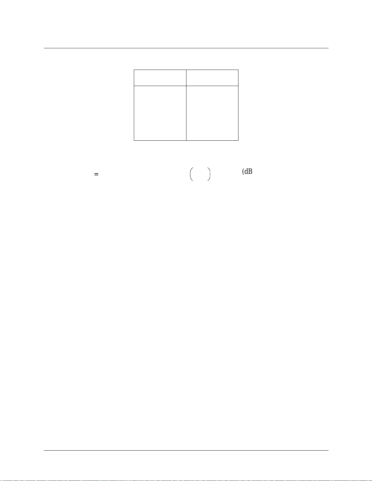
2. DECIBELS
The received signal power equation is often expressed in a decibel (dB) format, which turns the power
multiplication a nd division operations into addition and subtraction operations. In gener al , an y quantity
can be expressed in decibels . If the quant ity (x) is a power level, the decibel equivalent is defi ned as
x
If the quantity x is referenced to a milliwatt (mW), then the decibel-milliwatt (dBm) is used instead of a
generic decibel.
x
dBm
dB
10 log10x()⋅=
10 log
⋅=
x
------------ -
10
1mW
(dB)
(dBm)
3. RECEIVER POWER
The radio frequenc y (RF) signal power that is a vailable at the input to the receiving TRACER 420 5 system
is the next parameter of inter est in analyzing a wireless path. The TRACER 4205 has a maximum output
power level of 100 mW, which is equivalent to 20 dBm. This output signal will be attenuated and distorted
by various factors, all of which will degrade the original signal and affect the signal strength and quality as
sensed by the receiving unit. A simplified power budget analysis is beneficial to perform after verifying a
suitable line-o f-sight path to determine if the microwave path is suit able, even for ideal, non-distorted
signals.
The equation relatin g received signal power to the other microwave parameters is
PTGTG
---------------------------
=
P
R
4π()2d2L
2
λ
R
(watts, W)
14 © 2002 ADTRAN, Inc. 612804205L1-1A
Page 15

TRACER 4205 System Manual Section 2, Microwave Path Engineering Basics
where the variables in the equation are defined as
P
R
P
T
G
T
G
R
received p ow er (Watts)
transmitted power (100 mW (max) for TRACER 4205 - adjustable)
transmit antenna gain
receive ant enn a g ain
λ carrier wavelength (c / ƒ) (meters)
d pat h dist ance (meters)
L other losses (RF coaxial cable, etc.)
The actual tran smit and rec eive antenna gain va lues ar e str ictly depe ndent upon the physic al chara cte ristics
of the antennas install ed for each link. T ypical gains are between 20 and 40 dB. For example, a 4 foot
diameter Parabolic dish has 34.2 dB of gain at 5.8 GHz. The carrier wavelength is the physi cal wavelengt h
of the main RF carrier being used for communication, and is usually approximated at the center frequency
of the band, which is 5787.5 MHz. This gives a wavelength of 5. 18 cm.
The path distance is simply the physical distance between the transmit and receive antennas. For the
TRACER 4205 these distances can range up to 25 miles. The final parameter L incorporates all other
signal power losses in the microwave link, most of which are caused by antenna feed.
4. ANTENNA GAIN
Best performance will res ult from the use of a parabolic dish antenna. Antenna gain is determi ned by the
size of the dish, with typical features detailed below. Dish manufatureres will be able to supply gains for
other types of antennas.
Table 1. Antenna Gain for Given Dish Diameters
Dish Diameter
(in feet)
2 28.5
4 34.2
6 37.5
8 40.7
10 42.5
12 44.2
Gain
(in dBi)
612804205L1-1A © 2002 ADTRAN, Inc. 15
Page 16

Section 2, Microwave Path Engineering Basics TRACER 4205 System Manual
5. PATH LOSS
The expression
L
--------- -
==
P
λ
2
4πd
4πdf
----------- -
2
(dB)
c
where
f carrier frequency (Hz)
λ carrier wavelength (c / f) (meters)
d pat h dist ance (meters)
c speed of light, free-space (meters)
is called the path loss, and increases rapidly as either path length increases or carrier wavelength decreases
(which happens as the carrier frequency increases). So, longer microwave paths will naturally experienc e
more path loss than shorter paths. Likewise, higher frequency microwa ve communication will experience
more path loss than lower frequenc y microwave communication.
T able 1 tabulates path loss values for various path lengths for the TRACER 4205 system. Values not listed
in the table can be interp o lat ed from t hose l isted .
Table 2. Path Loss for Given Path Lengths
Path Length
(miles)
1112
2118
3 121
4 124
5 126
6 127
7 129
8 130
9 131
10 132
11 133
12 133
13 134
14 135
15 135
16 136
17 136
18 137
19 137
Path Loss
(dB)
16 © 2002 ADTRAN, Inc. 612804205L1-1A
Page 17
TRACER 4205 System Manual Section 2, Microwave Path Engineering Basics
Table 2. Path Loss for Given Path Lengths
Path Length
(miles)
20 138
21 138
22 139
23 139
24 139
25 140
Path Loss
(dB)
When using decibel notation, the received power equation becomes
4πdf
P
PTGTGRL– 20 · log
=
R
–++
----------- -
10
c
(dBm)
or
P
PTGTGRL– LP–++=
R
Where, in the second equation the path loss has been lumped into a single quantity, L
(dBm)
, as discussed
P
previously. When using decibel notation, it is necessary that al l quantities are individually converted to
decibels prior to performing addition and subtraction.
When d is expressed in miles and f in GHz, the path loss expression in deci bels becomes
L
96.6 20 log10d() 20·log+
P
10
f()⋅+=
(dB)
Figure 1 illustrate s a wireless link containing all of the parameter s previously discussed.
612804205L1-1A © 2002 ADTRAN, Inc. 17
Page 18

Section 2, Microwave Path Engineering Basics TRACER 4205 System Manual
P
L
L
λ
G
T
d, L
P
G
R
T
Figure 1. Example Microwave Path with Parameters
P
R
6. ANTENNA ALIGNMENT
With line-of-sight microwave communications, optimum system performance requires that the
transmitting a nd receivi ng a ntennas are proper ly aligne d. This will ensure m aximum recei ved signal p ower
at each receiver. Antenna alignment must be achieved in both azimuth (along a horizontal plane) and
elevation (along a vertical plane). A received sig nal strength indicator (RSSI) is used to aid the equipment
installer in deter mining when alignment is maximized, by simply ensuring maximu m RSSI. The RSSI
indicator for the TRACER 4205 system is provi ded through the VT100 terminal menus accessed through
the RS-232 inter face, and is present ed as a series of bars indicating signal strength. More bars means mo re
RSSI, which ensures more received signal strength and better link performance.
If the remote system has acqui red a useful signal from the remote system, then the remote TRACER 4205
RSSI can also be viewed from the local TRACER 4205 VT100 terminal menu interface.
An RSSI T est point is also provided on the front panel. The vol tage (relative to the gnd test point) present
on this test point represe nts a relative signal level of receive stre ngth from the far end. The voltage at this
test point can vary from approxi matly 0 to greater than 4 Volts DC, with 0 Volts correspondin g to no signal
and 4 Volts or better to full signal strength.
18 © 2002 ADTRAN, Inc. 612804205L1-1A
Page 19

TRACER 4205 System Manual Section 2, Microwave Path Engineering Basics
Antenna Beam Patterns
Directly related to the subject of antenna alignment is the topic of antenna beam patte rns. Antennas being
used with the TRACER 4205 system will have a particula r beam shap e determined in part by the physical
construction and geometr y of the antenna. The antenna beam patterns are character ized by a dominant
main lobe, which is the preferred lobe to use for point-to-point communicati ons, and several side lobes, as
shown in Figure 2 on page 19. The antenna alignm ent step to set ting up a microwa ve link is in f act steer ing
the main lobes of both a ntennas until the main lobe of one transmitter is centered on the receiving element
of the receiving antenna.
main lobe
side lobes
Figure 2. Typical Antenna Beam Pattern
Antennas are also designed to radiate RF energy efficiently for a specific range of frequencies. Please
consult the data shee t for your parti cular ante nna make and model to e nsure that it is specified to ope rat e in
the 5725 MHz to 5850 MHz frequency band.
Fresnel Zones, Earth Curvature, & Antenna Heights
The Fresnel zones correspond to r egions in the microwave path where reflections of the intended signal
occur and combine in both constructive and destructive manners with the main signal, thereby either
enhancing or reducing the net power at the receiver.
In general, the odd numbered Fresnel zo nes (1, 3, 5, ...) add constructively at the receiver, while the even
numbered Fresnel zones (2, 4, 6, ... ) add destructively at the receiver.
The first Fres nel z one corresp onds to the main lobe, and must b e at least 6 0% fr ee of ph ysical obstructi ons fo r
the path calculations to be valid . Since the main lobe contains the vast majorit y of the microwave ener g y, this
zone is typically used to determine proper antenna heights when placing antennas on towers or buildings.
The curvature of t he Earth be comes a legit imate obst ructi on for pa th length s of 7 mi les or greater, and must
also be accounted for when determining minimum antenna heights.
The aggregate expression f or minimum antenna height that incorporates both the 60% first Fresnel zone
and the Earth curvature is given by
h 72.1
d
---- - 0.125d
+= (feet)
2
4f
where f is in GHz and d is in miles.
612804205L1-1A © 2002 ADTRAN, Inc. 19
Page 20

Section 2, Microwave Path Engineering Basics TRACER 4205 System Manual
Table 3 tabulates minimum antenna heights for given path lengths.
Table 3. Minimu m An t enn a H eig ht f or Gi ve n P at h Len gt hs
Path Length
(miles)
222
432
641
850
10 60
15 86
20 117
25 153
Min. Antenna Height
(ft)
7. COAXIAL CABLE
Coaxial cable will be re quired to at tach the TRACER 4205 to t he ant enna. The length of the cable wi ll vary
from a few feet to several feet, depending upon your application and the proximity of the TRACER 4205
to the antenna.
Various grades of coaxial cable will work suff iciently well for connecting the TRACER 4205 unit to the
antenna. A low-loss coaxial cable is suggested to minimize cable losses. One end of the cable will require
an N-type male connector (plug) to mate with the TRACER 4205 unit. The other end of the coax will
require a con nector com patible wit h the antenna chose n for the i nstallati on, which is usually al so an N-type
male connector (plug). Additionally, it is recommended that both connector s on the coaxial cable be
weatherproofed from the elemen ts to prevent corrosion and electrical shorting.
T able 3 gives typical loss figures for some of the more common coaxial cable types, per 100 feet
Table 4. Typical Coaxial Loss for Common Cable Types, per 100ft
Cable Type Cable Loss (dB/ft)
RG-213, RG-214, RG-293 20
1/4” Coax 1 1.36
3/8” Coax 9.65
1/2” Coax 6.49
5/8” Coax 4.90
RG-58, RG-8 (air, foam) Not Recommended
7/8”, 1 1/4”, 1 5/8” Coax Not Recommended
5.8 GHz Elliptical Waveguide 1.23
In certain areas whe re lightning strikes are frequent, a lightning a rrestor should be installed directly on the
antenna coax. This will help protect the RF electronics in the downstream path from damaging voltages
and currents, including the TRACER 4205 unit.
20 © 2002 ADTRAN, Inc. 612804205L1-1A
Page 21

TRACER 4205 System Manual Section 2, Microwave Path Engineering Basics
8. RECEIVER SENSITIVITY
Receiver sensitivity is a value expressed in decibels referenced to one milliwatt (dBm) that corresponds to
the minimum amount of signal power needed at the receiver to achieve a given bit error rate (BER).
Receiver sensitivity is usually a negative number of decibels, and as such smaller receiver sensitivity is
better for a given BER. Several fact ors affect receiver sensitivity, including the data bandwidth of the
wireless link, and the amount of additional signal degradation introduced in the receiver electroni cs. The
receiver sensitivity of the TRACER 4205 is -78 dBm at 10
-6
BER.
9. FADE MARGIN
Fade margin is a val ue indicating the amount of extra si gnal power available to the receiver to operate at a
maximum bit error rat e (BER). Higher levels of fade margin are better, and will prot ect the viability of the
microwave link against signa l fading. For most applications, 20 to 30 dB of fade margin should ensure a
reliable link. Fade margin is simply the difference between the available signal power at the receiver and
the receiver sensit ivity, discussed previousl y:
FPRP
– PRGTGRL– LP– P
sens
–++==
sens
(dB)
10. PATH AVAILABILITY
The path availability of a wireless link is a metric that expresses the fractional amount of time a link is
available over some fixe d amount of time, and depends on several fa cto rs. Path availability is expr essed as
A 12.510
6–
×()abfd310
where the parameters are
a terrain factor
b climate factor
f carrier frequency (GHz)
d path length (miles)
F fade margin (dB)
The terrain factor is a quantity that compensates the link availability for different types of terrain.
Generally speaking, the more smooth an area's terrain is, the less availability a wireless link running over
that terrain will have, primar ily due to multipath r eflections . In contras t, secondary microwa ve signals will
be randomly dispers ed over rough te rrain , and will not int erfere with t he main signa l lob e as badly as in th e
smooth terrain case. The terrain factor values normally used are lis ted below:
F 10⁄–
()–[]100%×=
(dB)
Terrain Terrain Factor Description
Smooth 4 water, flat desert
Average 1 moderate roughness
Mountainous 1/4 very rough, mountainous
612804205L1-1A © 2002 ADTRAN, Inc. 21
Page 22

Section 2, Microwave Path Engineering Basics TRACER 4205 System Manual
The climate factor is a quantity that compensates the link availability for different types of climates
(weather). In general , micr owave links operating in areas with high humidity will have less availability
than those in arid are as , pri ma rily becau s e wat er is a dispersive mechan i sm t o mic ro w ave en erg y, and
causes the main signal lobe to refract and disperse away from the receiver location. The climate factor
values normally used are liste d below.
Climate Climate F a ctor Descrip t ion
Very Dry 1/8 desert regions
Temperate 1/4 mainland, interior region
Humid 1/2 humid and coastal regions
22 © 2002 ADTRAN, Inc. 612804205L1-1A
Page 23

ENGINEERING GUIDELINES
CONTENTS
Equipment Dimensions . . . . . . . . . . . . . . . . . . . . . . . . . . . . . . . . . . . . . . . . . . . . . . . . . . . . . . . . . . 2 4
Power Requirements . . . . . . . . . . . . . . . . . . . . . . . . . . . . . . . . . . . . . . . . . . . . . . . . . . . . . . . . . . . . 24
Reviewing the Front Panel Design . . . . . . . . . . . . . . . . . . . . . . . . . . . . . . . . . . . . . . . . . . . . . . . . . 24
RSSI Monitoring Interface. . . . . . . . . . . . . . . . . . . . . . . . . . . . . . . . . . . . . . . . . . . . . . . . . . . . . . 24
TX PWR Monitoring Interface. . . . . . . . . . . . . . . . . . . . . . . . . . . . . . . . . . . . . . . . . . . . . . . . . . . 25
Front Panel LEDs . . . . . . . . . . . . . . . . . . . . . . . . . . . . . . . . . . . . . . . . . . . . . . . . . . . . . . . . . . . . 25
Reviewing the TRACER 4205 Rear Panel Design . . . . . . . . . . . . . . . . . . . . . . . . . . . . . . . . . . . . . 26
Antenna Interface . . . . . . . . . . . . . . . . . . . . . . . . . . . . . . . . . . . . . . . . . . . . . . . . . . . . . . . . . . . . 27
Fuse . . . . . . . . . . . . . . . . . . . . . . . . . . . . . . . . . . . . . . . . . . . . . . . . . . . . . . . . . . . . . . . . . . . . . . 27
DC Power Connection. . . . . . . . . . . . . . . . . . . . . . . . . . . . . . . . . . . . . . . . . . . . . . . . . . . . . . . . . 27
Alarm Contacts . . . . . . . . . . . . . . . . . . . . . . . . . . . . . . . . . . . . . . . . . . . . . . . . . . . . . . . . . . . . . . 28
DS3 (In and Out) Connection . . . . . . . . . . . . . . . . . . . . . . . . . . . . . . . . . . . . . . . . . . . . . . . . . . . 28
RS-232 Connection (Terminal Use) . . . . . . . . . . . . . . . . . . . . . . . . . . . . . . . . . . . . . . . . . . . . . . 28
RS-232 Connection (Modem Use) . . . . . . . . . . . . . . . . . . . . . . . . . . . . . . . . . . . . . . . . . . . . . . . 30
At-A-Glance Specificatio ns . . . . . . . . . . . . . . . . . . . . . . . . . . . . . . . . . . . . . . . . . . . . . . . . . . . . . . . 31
FIGURES
Figure 1. TRACE R 4205 Front Panel Layout . . . . . . . . . . . . . . . . . . . . . . . . . . . . . . . . . . . . . . . . 24
Figure 2. TRACE R 4205 Rear Pa nel Layout. . . . . . . . . . . . . . . . . . . . . . . . . . . . . . . . . . . . . . . . . 27
TABLES
Table 1. TRACER 4205 Front Panel Description . . . . . . . . . . . . . . . . . . . . . . . . . . . . . . . . . . . . . 25
Table 2. TRACER 4205 LEDs . . . . . . . . . . . . . . . . . . . . . . . . . . . . . . . . . . . . . . . . . . . . . . . . . . . .25
Table 3. DC Power Connector Pinout . . . . . . . . . . . . . . . . . . . . . . . . . . . . . . . . . . . . . . . . . . . . . .27
Table 4. Alarm Contact Connector Pinout . . . . . . . . . . . . . . . . . . . . . . . . . . . . . . . . . . . . . . . . . . .28
Table 5. RS-232 Connection Pinout . . . . . . . . . . . . . . . . . . . . . . . . . . . . . . . . . . . . . . . . . . . . . . . 29
Table 6. TRACER 4205 (DCE) to Terminal (DTE) Diagram (DB-25) . . . . . . . . . . . . . . . . . . . . . .29
Table 7. TRACER 4205 (DCE) to Personal Computer (DB-9) . . . . . . . . . . . . . . . . . . . . . . . . . . . 29
Table 8. TRACER 4205 (DCE) to Modem (DCE) . . . . . . . . . . . . . . . . . . . . . . . . . . . . . . . . . . . . . 30
612804205L1-1A © 2002 ADTRAN, Inc. 23
Page 24

Section 3, Engineering Guidelines TRACER 4205 System Manua l
1. EQUIPMENT DIMENSIONS
The TRACER 4205 unit is 19” W, 10.5” D, and 1.75” H, weighs 7 lbs, and can be used in rack-mount
configurations.
2. POWER REQUIREMENTS
The TRACER 4205 system has a maximum power consumption of 25W and a maximum current draw of
1.2A (at 21 VDC).
3. REVIEWING THE FRONT PANEL DESIGN
The front panel contains a singl e control switch for activating a DS3 line loopback , RSSI and TX PWR
monitoring interfa ces, a GND interface for reference with the monitor ing interfaces, and status LEDs to
provide visual inf ormation about the TRACER 4205 system. Figur e 1 identifies the DS3 loopback switch,
the various bantam inter faces, and the LEDs.
DS3 Loopback
Status LEDs
Switch
RSSI
Figure 1. TRACER 4205 Front Panel Layout
TX PWR
GND
RSSI Monitoring Interface
The RSSI voltage is a function of the signal strength at the receiver and is used to measure the received
signal strength. RSSI varies approximately from 0 to greater than 4 Volts (V), with 0V corresponding to a
weaker received signal and 4V or better corresponding to a stronger received sig nal.
The voltage level present at the RSSI test point represents only a relative signal level of
receiv e strength from the far end. No direct correlation can be made between RSSI voltage
levels and actual receive levels in dBm. This test point is provided to assess relative signal
level for alignment of antennas.
24 © 2002 ADTRAN, Inc. 612804205L1-1A
Page 25

TRACER 4205 System Manual Section 3, Engineering Guidelines
TX PWR Monitoring Interface
The TX PWR voltage is a function of the selected tr ansmit power le vel. Thi s voltage ranges appr oximately
from 0 to 5V, with 0V corresponding to +5 dBm (3 milliwatts) and 5V corresponding to +20 dBm (100
milliwatts).
Front Panel LEDs
With the TRACER 4205 powered-on, the front panel LEDs provide visual information about the status of
the TRACER 4205 system. Table 1 provides a brief description of the front panel features, and Table 2
(continued on page 27) provide s detailed information about the LEDs.
Table 1. TRACER 4205 Front Panel Description
Feature Description
DS3 Loopback Switch Allows quick activation/deactivation of DS3 line loopbacks
RSSI Interface DC voltage indicating strength of the received signal at the antenna
TX PWR Interface DC voltage indicating strength of transmitted signal
GND Interface Ground reference for RSSI and TX PWR Interfaces
Status LEDs Provides status information about the system
Table 2. TRACER 4205 LEDs
For these LEDs... This color light... Ind icates that...
PWR Green (solid) the TRACER 4205 is connected to a power source.
Off the TRACER 4205 is not currently powered up.
PLAN A Green (solid) the TRACER 4205 is transmitting on Frequency Plan A.
Off the TRACER 4205 is not transmitting on Frequency
Plan A.
PLAN B Green (solid) the TRACER 4205 is transmitting on Frequency Plan B.
Off the TRACER 4205 is not transmitting on Frequency
Plan B.
RF DOWN R ed (solid) there is a commun ication problem betwe en the local and
remote TRACER 4205 systems.
RF LOW Red (solid) the RSSI level is below suggested minimum threshold.
TST Amber (solid) unit is performing power-on self-test.
RAI Red (solid) the TRACER 4205 received a remote alarm in the DS3 EOC
channel (bits X1 and X2 are both set to zero).
612804205L1-1A © 2002 ADTRAN, Inc. 25
Page 26

Section 3, Engineering Guidelines TRACER 4205 System Manua l
Table 2. TRACER 4205 LEDs (Continued)
For these LEDs... This color light... Ind icates that...
AIS Red (solid) the TRACER 4205 received a remote alarm from a connected
DS3 device (properly aligned and framed alternating one-zero
pattern).
LOF Red (solid) the TRAC ER 4205 DS3 framer has lost alignment (due to
receiving too many F or M bits in error).
LOS Red (solid) the TRACER 4205 does not detect a DS3 from the connected
DS3 device signal (indicated by receiving 192 consecutive
zeros).
BPV Red (solid) the TRACER 4205 detects Bipolar Violations on the received
signal from the connected DS3 device (receiving two
consecutive “one” bits with the same polarity).
LBK Amber (solid) the TRACER 4205 is currently in DS3 line loopback.
Amber (flashing) the TRACER 4205 is currently in DS3 link loopback.
4. REVIEWING THE TRACER 4205 REAR PANEL DESIGN
The TRACER 4205 rear panel contains the followi ng interfaces:
ALARM interface (terminal block) for connecting to an external alarm monitoring system
•
DC POWER (terminal block) for connecting to a proper 21-63 VDC power source
•
DS3 IN and OUT (BNC interfaces) fo r co nne ct ing t o a DS3 dev ice
•
• Antenna (N-Type connector) for the antenna feedline cable
• Ground lug for connecting to earth gr ound
RS-232 (DB-25 female) for connecting to a VT100 terminal or PC with terminal emulation
•
software
Figure 2 on page 27 identifies the various features of the TRACER 4205 rear panel. A detailed discussion
of all interfaces (inc luding pinouts, where applicable) follows the figure.
26 © 2002 ADTRAN, Inc. 612804205L1-1A
Page 27

TRACER 4205 System Manual Section 3, Engineering Guidelines
RS232 Interface
(VT100 Terminal)
DS3 In
(Receive)
DS3 Out
(Transmit)
Alarm
DC Power Connection
Fuse
Contacts
Figure 2. TRACER 4205 Rear Panel Layout
Antenna
Connector
Ground
Lug
Antenna Interface
The ANTENNA interface (N-Type connector) connects to the antenna (customer supplied) using standard
antenna feedline cable . When determining the cable specifica tions for your application, refer to Sec tion 2,
Microwave Path Engineering Basics (Coaxial Cable on page 20) for a discussion on cable length and loss
factors.
Fuse
The fuse holder, accessible from the rear panel of the TRACER 4205, accepts a generic 1 Amp, 2-inch
slow-blo fuse.
DC Power Connection
The TRACER 4205 can operate from a suppl y between 21 and 63 VDC, with either polarity referenced to
ground, and consumes less than 25 Watts (W). Power supplies should be able to provide up to 30 W at
the selected voltag e. Current required (in amps) is determined by dividing the power consumed (in watts)
by the applied voltage (in volt s). For example, at 48 V, TRACER 4205 would draw approximately 0.52 A
(25 W/48 V).
Connec tor t ype Terminal Block
Table 3. DC Power Connector Pinout
PIN NAME DESCRIPTION
1 + POSITIVE LEAD (referenced to ground)
2 - NEGATIVE LEAD (referenced to ground)
612804205L1-1A © 2002 ADTRAN, Inc. 27
Page 28

Section 3, Engineering Guidelines TRACER 4205 System Manua l
Alarm Contacts
Normally open (NO) and normally closed (NC) alarm conta cts are provided on the rear panel of the
TRACER 4205 system. In normal operation, the NC contact is electrically connected to the common
contact (COM) and the NO contact is isolated. During an alarm condition, the NC contact becomes
isolated and the NO is electri cally connected to COM. This allows alarm conditions to be reported to
external alarm monitoring systems.
Connec tor t ype Terminal Block
Table 4. Alarm Contact Connector Pinout
PIN NAME DESCRIPTION
1 COM COMMON CONTACT
2 NO NORMALLY-OPEN CONTACT
3 NC NO RMALLY-CLOSED CONTACT
DS3 (In and Out) Connection
The physical DS3 interface is provided by a pair of 75 Ω BNC connectors for transmit and receive.
The shielding on both BNC connectors are grounded pe r ANSI T1.4 04.
RS-232 Connection (Terminal Use)
The RS-232 connector provides a female DB-25 terminal connec tion (wired as a DCE interface), whic h is
used for terminal access to the TRACER 4205 system. The RS-232 port provides the following functions:
• Accepts EIA-232 input from a PC or terminal for controlling the TRACER 4205 system
• Operates at 9600 bps
T abl e 5 on page 29 shows the pinout. W i ring dia grams for conne cting to the RS -232 connector (for var ious
applications) are provided following the pinout.
28 © 2002 ADTRAN, Inc. 612804205L1-1A
Page 29

TRACER 4205 System Manual Section 3, Engineering Guidelines
Connec tor t ype (USOC) DB-25
Table 5. RS-232 Connection Pinout
PIN NAME DESCRIPTION
1, 7 GND GROUND
2TXTRANSMIT
3 RX RECEIVE
4 RTS REQUEST TO SEND
5 CTS CLEAR TO SEND
6 DSR DATA SET READY (MODEM CONTR OL ONLY)
8 CD CARRIER DETECT
9-19 — UNUSED
20 DTR DATA TERMINAL READY (MODEM CONTROL ONLY)
21 — UNUSED
22 RI RING INDICATOR
23-25 — UNUSED
Table 6. TRACER 4205 (DCE) to Terminal (DTE) Diagram (DB-25)
PIN NAME PIN NAME
2TX 2 TX
3RX 3 RX
4RTS 4 RTS
5CTS 5 CTS
6 DSR 6 DSR
7GND 7 GND
Table 7. TRACER 4205 (DCE) to Personal Computer (DB-9)
PIN NAME PIN NAME
2TX 2 TX
3RX 3 RX
4RTS 7 RTS
5CTS 8 CTS
6 DSR 6 DSR
7GND 5 GND
612804205L1-1A © 2002 ADTRAN, Inc. 29
Page 30

Section 3, Engineering Guidelines TRACER 4205 System Manua l
RS-232 Connection (Modem Use)
Modem controls, discussed in Section 5, User Inte rface Guide, of this manual, will enable or disable
modem control through the RS-232 inter face. When this option is enabled from a standard terminal
connection, all RS-232 communications will cease until a modem is attached with a null modem adapter
between the TRACER 4205 and the data modem. The data modem should be configured for AUTO
ANSWER and 9600 bps. When the user connects via modem to the TRACER 4205 unit, communications
via the RS-232 port will resume. If a user accidenta lly enables modem control from a termina l and disr upts
the RS-232 communication, pr essing <Ctrl + Z> three times will temporarily disable the modem control
option (until the system is reset) and access the system configuration to disable modem control.
The TRACER 4205 must be interfaced to a modem via an RS-232 null modem adapter or cable. The null
modem will convert Clear To Send (CTS) and Data Set Ready (DSR) into Read y To Send (RTS) a nd Dat a
T erminal Ready (DTR), respectiv ely. The se signals will indicate (to most modems) that a valid DTE
terminal device is pr esent. The null mo dem interfac e must rout e Carrie r Detect ( CD) on pin 8 di rectly fr om
the mod em, and the mod em must source CD only when actu ally connect ed to a carrier when using the
RS-232 interface for modem control.
When
MODEM CONNECTION is selected in the menu system, the TRACER 4205 will de-assert DTR and
DSR for a time greater than 20 ms. The null modem will consequently drop DTR and RTS at the modem
interface, signaling the modem to hang up the line. If password functionality is enabled in the TRACER
4205, selecting MODEM CONNECTION (logout) will reset the TRACER 4205 to the password entry screen.
Hangup-on-DTR-drop may need to be explicitly enabled on some modems.
T able 8 contains the wiring diagram needed for connecting the TRACER 4205 RS-232 interface to a
modem using the null modem adapter.
Table 8. TRACER 4205 (DCE) to Modem (DCE)
PIN NAME PIN NAME
2TX 3 RX
3RX 2 TX
4 RTS 5 CTS
5 CTS 4 RTS
6DSR 20 DTR
7GND 7 GND
8CD 8 CD
30 © 2002 ADTRAN, Inc. 612804205L1-1A
Page 31

TRACER 4205 System Manual Section 3, Engineering Guidelines
5. AT-A-GLANCE SPECIFICATIONS
The following is a list of specifications for the TRACER 4205 system.
Hardwa re Description Specification
Transmitter
Output Pow er +20 dBm, m ax
Frequency Range 5725 to 5850 MHz
Receiver
Receive Level, Range -30 to -78 dBm
Receive Level, Maximum -30 dBm
Receive Level, Nominal -50 dBm
Frequency Plan
Plan A Tx 5.747 GHz, Rx 5.800 GHz
Plan B Tx 5.827 GHz, Rx 5.750 GHz
DS3 Interface
User Interface
VT100 Terminal Interface
Capacity 44.736 Mbps
Connection dual 75 Ω BNC connectors (Tx and Rx)
Line Code B3ZS
Framing M13, C-Bit Parity
Alarms AIS, Red, Yellow, BPVs
Loopbacks Lo ca l and remote (line and link)
Diagnostics DS3 Line and Link Loopbacks
Test Points RSSI, Tx PWR
Data Rate 9600 bps
Data Bits 8
Parity None
Stop Bits 1
Terminal Emulation VT100
612804205L1-1A © 2002 ADTRAN, Inc. 31
Page 32

Section 3, Engineering Guidelines TRACER 4205 System Manua l
Hardware Description Specification
Mechanical and Environmental
Operating Te mpe rature -25º C to 65ºC
Size 19” W x 10.5” D x 1.75” H
Humidity 95%, Non-condensing
Weight 7 lbs
Power
Input Voltage 21 to 63 VDC, either polarity
referenced to ground
Power Consumption <
25 Watts
Connector 2 pin terminal block (DC)
Fuse 1 amp, 250 Volt slow-blo fuse (2-inch)
32 © 2002 ADTRAN, Inc. 612804205L1-1A
Page 33

NETWORK TURNUP PROCEDURE
CONTENTS
Introduction . . . . . . . . . . . . . . . . . . . . . . . . . . . . . . . . . . . . . . . . . . . . . . . . . . . . . . . . . . . . . . . . . . . .34
Tools Required . . . . . . . . . . . . . . . . . . . . . . . . . . . . . . . . . . . . . . . . . . . . . . . . . . . . . . . . . . . . . . . . . 3 4
Unpack and Inspect the System . . . . . . . . . . . . . . . . . . . . . . . . . . . . . . . . . . . . . . . . . . . . . . . . . . . 34
Contents of ADTRAN Shipment . . . . . . . . . . . . . . . . . . . . . . . . . . . . . . . . . . . . . . . . . . . . . . . . . 34
Customer Provides . . . . . . . . . . . . . . . . . . . . . . . . . . . . . . . . . . . . . . . . . . . . . . . . . . . . . . . . . . . 3 4
Channel Selection . . . . . . . . . . . . . . . . . . . . . . . . . . . . . . . . . . . . . . . . . . . . . . . . . . . . . . . . . . . . . . 35
Grounding Instructions . . . . . . . . . . . . . . . . . . . . . . . . . . . . . . . . . . . . . . . . . . . . . . . . . . . . . . . . . . 35
Supplying Po wer to the Unit . . . . . . . . . . . . . . . . . . . . . . . . . . . . . . . . . . . . . . . . . . . . . . . . . . . . . .36
Mounting Options . . . . . . . . . . . . . . . . . . . . . . . . . . . . . . . . . . . . . . . . . . . . . . . . . . . . . . . . . . . . . . . 36
Connecting the DS3 Interface . . . . . . . . . . . . . . . . . . . . . . . . . . . . . . . . . . . . . . . . . . . . . . . . . . . . . 36
FIGURES
Figure 1. Bandwidth Division. . . . . . . . . . . . . . . . . . . . . . . . . . . . . . . . . . . . . . . . . . . . . . . . . . . . . 3 5
612804205L1-1A © 2002 ADTRAN, Inc. 33
Page 34

Section 4, Network Turnup Procedure TRACER 4205 System Manual
1. INTRODUCTION
This section discusses the installation process of the TRACER 4205 system.
Changes or modifications not expressly approved by ADTRAN could void the user’s
authority to operate the equipment.
2. TOOLS REQUIRED
The tools required for the ins tallation of the TRACER 4205 are:
• VT100 terminal or PC with terminal emulation software
• RS-232 (DB-25 male for TRACER 4205 end) cable for c onnecting to terminal
To prevent electr ical sho ck, do not inst all equipmen t in a wet loc ation or du ring a ligh tning
storm.
3. UNPACK AND INSPECT THE SYSTEM
Each TRACER 4205 is shipped in its own cardboard shipping carton. Open each carton carefully and
avoid deep penetration into the carton with sharp objects.
After unpacking the unit, inspect it for possible shipping damage. I f the equipment has been damaged in
transit, immed i atel y file a cl ai m wi th the carri er, then cont act A D TRA N Cus tom er Serv i ce (see Warranty
and Customer Service information in the front of this manual).
Contents of ADTRAN Shipment
Your ADTRAN shipment includes the following items:
• TRACER 4205 unit
• TRACER 4205 Documentation CD
Customer Provides
The following items are necess ary for the installation of the TRACER 4205 system and are not provided
by ADTRAN:
• 21 to 63 VDC power source (or AC adapter availa ble from ADTRAN P/N 1280650L1), either polar ity
referenced to ground
• Antenna and mounting hardware
• Antenna feedline cabl e
• DS3 cables (BNC for TRACER 4205 end) for connecting to DS3 equipment
34 © 2002 ADTRAN, Inc. 612804205L1-1A
Page 35

TRACER 4205 System Manual Section 4, Network Turnup Proce dure
4. CHANNEL SELECTION
The FCC has allocated 100 MHz of spectrum in the band in which the TRACER 4205 operates. Figur e 1
illustrates the bandwidth division.
A
5747 MHz
Channel Plan describes which lobe is transmitted upon.
Example: A will transmit at A lobe and receive at B.
Figure 1. Bandwidth Division
5827 MHz
B
To designate the utilization of the ISM bandwidth, there are two different channel plans, labeled A and B.
The letter of each channel plan setting is preset by the factory and refers to the physica l configuration of
the diplexer filte r inside the environmental housing. The transmitter at one end of the link will transmit in
the lower portion of the spectrum and recei ve in the upper portion. Consequently, the receiver at the other
end should receive in the lower portion and transmit in the upper portion. There is one rule for successful
TRACER 4205 configuration.
1. The letter of the channel plan must be d iff erent on both ends . Shipment of a li nk will cons ist o f one
Plan A and Plan B unit.
5. GROUNDING INSTRUCTIONS
The following provides grounding instruction information from the Underwriters’ Laboratory UL 60950
Standard for Safe ty of Information Technology Equipment Inclu ding Electrical Business Equipment, of
December, 2000.
An equipment grounding conduct or that is not smaller in size than the ungrounded branch-circuit supply
conductors is to be installe d as part of the circuit that supplies the product or system. Bare, covered, or
insulated grounding c onductors are acceptable. Indivi dually covered or insulated equipment grounding
conductors shall have a continuous outer finish that is either green, or green with one or more yellow
stripes. The equipment grounding conductor is to be connected to ground at the service equipment.
The attachment-plug receptacles in the vicinity of the product or system are all to be of a grounding type,
and the equipment grounding conduc tors serving these receptacles are to be connected to earth ground at
the service equi pment.
A supplementary equipment grounding conductor shall be installed be tween the product or system and
ground that is in addition to the equipm ent grounding conductor in the power supply cord.
612804205L1-1A © 2002 ADTRAN, Inc. 35
Page 36

Section 4, Network Turnup Procedure TRACER 4205 System Manual
The supplementary equipment gr ounding conductor shall not be smaller in size than the ungr ounded
branch-circuit supply conductors. The supplementary equipment grounding conductor shall be connected
to the product at the terminal pro vide d, a nd shall be connected to ground in a manner that will retain the
ground connection when the produc t is unplugged from the receptacle. The connection to ground of the
supplementary equip ment grounding conductor shall be in compliance with the rule s for terminating
bonding jumpers at Part K or Artic le 250 of the National Electrical Code, ANSI/NFPA 70. Termination of
the supplementary equipm ent grounding conductor is permitted to be made to building ste el, to a metal
electrical raceway system, or to any grounded item that is permanently and reliably connected to the
electrical ser vice equipment ground.
The supplemental grounding con ductor sha ll be conne cted to t he equipment using a number 8 ring t erm inal
and should be fastened to the gro unding lug provi ded on the rear panel of th e equipment . The ring termin al
should be installed using the appropriate crimping tool (AMP P/N 59250 T-EAD Crimping Tool or
equivalent.)
The supplemental equipment grounding terminal is located on the rear panel of the
TRACER 4205.
6. SUPPLYING PO WER TO THE UNIT
The TRACER 4205 can operate from a suppl y between 21 and 63 VDC, with either polarity ref erenced to
ground. Power supplies should be able to provide up to 30 watts at the selected voltage. A dual pin
terminal plug accepts power at the rear panel of the unit, providing a + and - polarity reference point.
Adapters for this plug are available (P/N 1175043L2) and are furnished with the unit and optional power
supply (P/N 1280650L1).
7. MOUNTING OPTIONS
Install th e TRACER 4205 in a l ocation that requir es minimal antenna feedline length (the loss in this cable
directly aff ects overall system performance) . The TRACER 4205 is design ed to be mounted in a rack. I f
multiple units are insta lled in one location, one half inch of spacing is recommended above and below the
unit.
8. CONNECTING THE DS3 INTERFACE
The physical DS3 interface is provided using a pair of 75 Ω BNC connectors for transmit and receive.
Using standard coaxial cable, connect the
interface of the DS3 equipment . Connec t the DS3 IN interface of the TRACER 4205 to the transmit data
interface of the DS3 equipment .
DS3 OUT interface of the TRACER 4205 to the receive data
36 © 2002 ADTRAN, Inc. 612804205L1-1A
Page 37

USER INTERFACE GUIDE
CONTENTS
Navigating the Terminal Menu . . . . . . . . . . . . . . . . . . . . . . . . . . . . . . . . . . . . . . . . . . . . . . . . . . . . 38
Terminal Menu Window . . . . . . . . . . . . . . . . . . . . . . . . . . . . . . . . . . . . . . . . . . . . . . . . . . . . . . . 38
Navigating using the Keyboard Keys . . . . . . . . . . . . . . . . . . . . . . . . . . . . . . . . . . . . . . . . . . . . . 39
Terminal Menu and System Control . . . . . . . . . . . . . . . . . . . . . . . . . . . . . . . . . . . . . . . . . . . . . . . .39
Password Protection. . . . . . . . . . . . . . . . . . . . . . . . . . . . . . . . . . . . . . . . . . . . . . . . . . . . . . . . . . 39
Menu Descriptions . . . . . . . . . . . . . . . . . . . . . . . . . . . . . . . . . . . . . . . . . . . . . . . . . . . . . . . . . . . . . .40
>TRACER System Status. . . . . . . . . . . . . . . . . . . . . . . . . . . . . . . . . . . . . . . . . . . . . . . . . . . . . . 40
>Main Menu . . . . . . . . . . . . . . . . . . . . . . . . . . . . . . . . . . . . . . . . . . . . . . . . . . . . . . . . . . . . . . . . 42
>TRACER System Configuration . . . . . . . . . . . . . . . . . . . . . . . . . . . . . . . . . . . . . . . . . . . . . . . . 43
>TRACER Link Performance History . . . . . . . . . . . . . . . . . . . . . . . . . . . . . . . . . . . . . . . . . . . . . 45
>DS3 Status/Configuration/Loopback. . . . . . . . . . . . . . . . . . . . . . . . . . . . . . . . . . . . . . . . . . . . . 46
>DS3 Performance History . . . . . . . . . . . . . . . . . . . . . . . . . . . . . . . . . . . . . . . . . . . . . . . . . . . . . 48
FIGURES
Figure 1. Main Menu Screen. . . . . . . . . . . . . . . . . . . . . . . . . . . . . . . . . . . . . . . . . . . . . . . . . . . . . 38
Figure 2. TRACER System Status . . . . . . . . . . . . . . . . . . . . . . . . . . . . . . . . . . . . . . . . . . . . . . . . 40
Figure 3. Main Menu . . . . . . . . . . . . . . . . . . . . . . . . . . . . . . . . . . . . . . . . . . . . . . . . . . . . . . . . . . . 42
Figure 4. TRACER System Configuration. . . . . . . . . . . . . . . . . . . . . . . . . . . . . . . . . . . . . . . . . . . 43
Figure 5. TRACER Link Performance History. . . . . . . . . . . . . . . . . . . . . . . . . . . . . . . . . . . . . . . . 45
Figure 6. DS3 Status/Configu ra tion/Loopbac k . . . . . . . . . . . . . . . . . . . . . . . . . . . . . . . . . . . . . . . 46
Figure 7. DS3 Link Loopback . . . . . . . . . . . . . . . . . . . . . . . . . . . . . . . . . . . . . . . . . . . . . . . . . . . . 47
Figure 8. DS3 Line Loopba ck . . . . . . . . . . . . . . . . . . . . . . . . . . . . . . . . . . . . . . . . . . . . . . . . . . . . 48
Figure 9. DS3 Link Performance Hi story. . . . . . . . . . . . . . . . . . . . . . . . . . . . . . . . . . . . . . . . . . . . 48
TABLES
Table 1. DS3 Interface Alarms . . . . . . . . . . . . . . . . . . . . . . . . . . . . . . . . . . . . . . . . . . . . . . . . . . . 4 6
612804205L1-1A © 2002 ADTRAN, Inc. 37
Page 38

Section 5, User Interface Guide TRACER 4205 System Manual
1. NAVIGATING THE TERMINAL MENU
The TRACER 4205 menu system can be accessed with a VT100 compatible terminal set to 9600 bits per
second, 8 data bits, 1 stop bit, and no parity, connected to the RS-232 port located on the back of the unit.
Flow control on the serial inte rface should be configured to None for proper operation. Once a terminal is
connected, pre ssin g <C tr l + L> wil l refres h the curr en t scre en . If pas sw or d acces s has been en abl ed , the
ENTER PASSWORD message will be displayed at the bottom of the TRACER 4205 system status menu.
All TRACER 4205 systems ar e shipped factory default with password protection disabled.
Terminal Menu Window
The TRACER 4205 uses five menu pages and a single main menu page to access its many features. The
main menu page (see Figure 1) provides a link to all available configuration/status pages.
After connecting a VT100 terminal to the TRACER 4205, press <Ctrl + L> to redraw the
current screen. VT100 access will not be possible until this step is performed.
Figure 1. Main Menu Screen
38 © 2002 ADTRAN, Inc. 612804205L1-1A
Page 39

TRACER 4205 System Manual Section 5, User Interface Guide
Navigating using the Keyboard Keys
You can use various keystrokes to move through the terminal menu, to manage a terminal menu se ssion,
and to configure the system.
Moving through the Menus
To do this... Press this key...
Move up to select items Up Arrow
Move down to select items Down Arrow
Edit a selected menu item Enter
Scroll through configuration parameters for a menu item Spacebar
Left/ Righ t Arrows
P or N (Prev/Next)
Cancel an edit Escape
Return to Main Menu page M
Session Management Keystrokes
To do this... Press this key...
Log into a session Spacebar
Refresh the screen
To save time, only the portion of the screen that has changed is refreshed. This
option should only be necessary if the display picks up incorrect characters
<Ctrl + L>
2. TERMINAL MENU AND SYSTEM CONTROL Password Prot ection
The TRACER 4205 provide s optio nal password pr ot ection of t he termina l interfac e. If enable d, a passwor d
prompt is presented at power-up, reboot, modem logout, or after ten minute s of inactivity on the terminal.
Password protection is enabled and a password is defined via the system configuration menu.
All TRACER 4205 systems ar e shipped factory default with password protection disabled.
If the password is forgotten, physical access to the TRACER 4205 unit is required to access the terminal
interface. The password may be bypassed by pressing the
This disabled the password and will initialize the TRACER 4205 system status menu to allow the
password to be changed (via the configuration screen).
DS3 LBK button while the system is rebooted.
Rebooting the unit to bypass password protection and redefine the installed password is
service affecti ng.
612804205L1-1A © 2002 ADTRAN, Inc. 39
Page 40

Section 5, User Interface Guide TRACER 4205 System Manual
3. MENU DESCRIPTIONS
The remainder of this section describes the TRACER 4205 menus and submenus.
The menu structur e of the TRACER 4205 system is depicted below as follows:
> MENU PAGE
> MENU PAGE > MENU SELECTION
> MENU PAGE > MENU SELECTION > SUB-MENU
>TRACER SYSTEM STATUS
Figure 2 shows the TRACER System Status menu page. Status of maj or system components for both sides
of the TRACER link are displayed, but no configuration can be performed from this view.
Figure 2. TRACER System Status
The top of the TRACER System Status menu page display s the elapsed time the TRACER 4205 system
has been operational sinc e the last power reset. Located directly beneath the ADTRAN Technical Support
phone number is a graphical indi cator of the stat us of the TRACER 4205 DS3 and RF links (as rep orted by
both the local and remote units). The
DS3 labels will be reverse highli ghte d if any error c onditi ons exist on
that DS3 in t e rface.
The status of the rece ived radio link is indicate d as RF UP or RF DOWN for each direction. The left portion
of the menu page reports the status of the local TRACER 4205 (the system where the active terminal is
attached). The right portion of the screen reports the status of the remote system. If the RF link is down
from the remote unit to the local unit,
LOCAL RX LINK ERROR will be displayed. If the RF link is down from
the local unit to the remote unit, or if the RF link status cannot be determined, REMOTE RX LINK ERROR will
be displayed.
40 © 2002 ADTRAN, Inc. 612804205L1-1A
Page 41

TRACER 4205 System Manual Section 5, User Interface Guide
Press <0> from any menu in the TRACER 4205 VT100 menu structure to access the
TRACER System Status page.
>TRACER SYSTEM STATUS > FREQUENCY PLAN
Displays the frequency pla n (A or B) for the TRACER 4205 unit. For an operational TRACER 4205
system, the local and remote units should display opposite frequency pla ns.
>TRACER SYSTEM STATUS > SITE
Displays the site name config ured from the TRACER System Configuration page.
>TRACER SYSTEM STATUS > RX POWER
Displays the appr oximate re ceiver le vels ( for both t he local and remote units ) us ing a ser ies of symbols (#).
The more symbols (#) displayed, the stronger the signal. If the link is down and remote end data is
unavailable, DATA NOT AVAILABLE is displayed in place of the symbols (#).
>TRACER SYSTEM STATUS > TX POWER
Displays the approximate transmitter levels (for both the local and remote units) using a series of symbols
(#). The more symbols (#) displayed, the stronger the signal. If the link is down and remote end data is
unavailable,
DATA NOT AVAILABLE is displayed in place of the symbols (#).
612804205L1-1A © 2002 ADTRAN, Inc. 41
Page 42

Section 5, User Interface Guide TRACER 4205 System Manual
>MAIN MENU
The TRACER 4205 Main Menu page provides access to all other configuration/status pages. Figure 3
shows the TRACER Main Menu page.
Figure 3. Main Menu
Use the up and down arrow keys to scroll through the available pages, or enter the number of the selected
page (to highlight the menu page) and pre ss <Enter>.
Press <M> from any menu in the TRACER 4205 VT100 menu structure to access the
TRACER Main Menu page.
42 © 2002 ADTRAN, Inc. 612804205L1-1A
Page 43

TRACER 4205 System Manual Section 5, User Interface Guide
>TRACER SYSTEM CONFIGURATION
Figure 4 shows the TRACER System Configuration menu page. System configuration parameters for both
the local and remote TRACER 4205 units are available through this menu page.
Figure 4. TRACER System Configuration
Press <1> from any menu in the TRACER 4205 VT100 menu structure to access the
TRACER System Configuration menu page.
>TRACER SYSTEM CONFIGURATION > RX POWER
Displays the appr oximate re ceiver le vels ( for both t he local and remote units ) us ing a ser ies of symbols (#).
The more symbols (
#) displayed, the stronger the signal. If the link is down and remote end data is
unavailable, DATA NOT AVAILABLE is displayed in place of the symbols (#). This parameter is display only.
>TRACER SYSTEM CONFIGURATION > TX POWER
Allows the transmitter levels (for both the local and remote units) to be adjusted. The current transmitter
level is di splayed using a series of symbols (#). The more symbols (#) displayed, the stronger the signal. If
the link is down and remote end data is unavailable, DATA NOT AVAILABLE is displayed in place of the
symbols (#).
Reducing the transmitter power of the remote TRACER 4205 could negatively impact the
TRACER RF link.
612804205L1-1A © 2002 ADTRAN, Inc. 43
Page 44

Section 5, User Interface Guide TRACER 4205 System Manual
>TRACER SYSTEM CONFIGURATION > SITE NAME
Enter up to 32 alphanumeric characters to be displayed for identification of the TRACER 4205 system.
>TRACER SYSTEM CONFIGURATION > MODEM CONTROL
Configures the modem control leads on the RS-232 port (termi nal interfa ce located on the rear pa nel of the
unit). Set MODEM CONTROL to ENABLED when connecting the unit to a modem (using a null modem
adapter). Setting
enables data to be sent to the VT 100 continuously.
MODEM CONTROL to DISABLED prevents the TRACER 4205 from monitoring DCD and
MODEM CONTROL must be set to DISABLED when the
VT100 terminal is in use. The TRACER 4205 comes factory programmed with MODEM CONTROL set t o
DISABLED.
Press <Ctrl+Z> three times from the terminal interface to temporarily disable MODEM
ONTROL when the modem control le ads are active.
C
>TRACER SYSTEM CONFIGURATION > MODEM CONNECTION (LOGOUT)
Activator to c ause the TRACER 4205 t o de -assert C lear To Send (CTS) and DSR for a ti me greater than 20
milliseconds. This signals the modem to disconnect the analog connection. Hangup-On-DTR-Drop may
need to be explicitly enabled on some modems. If PASSWORD PROTE CTION is ENABLED, this menu also
causes the unit to close the curr ent session and return to the TRACER System Status menu page and wait
for passwor d input .
>TRACER SYSTEM CONFIGURATION > PASSWORD ENABLE
Configures password prote ction for the VT100 terminal interface. Password protection for the TRACER
4205 requires password inpu t from the TRACER System Status menu page when connecting to the unit.
When configured for Password protection, the TRACER 4205 closes any terminal session that remains
inactive for more than 10 minutes. The TRACER 4205 comes factory programmed with
NABLE set to DISABLED.
E
PASSWORD
>TRACER SYSTEM CONFIGURATION > PASSWORD
Sets the password for password protection of the TRACER 4205 VT100 terminal interface. Enter up to 8
alphanumeric chara cter s. The system password is case sensitive.
The default password for the TRACER 4205 is tracer.
>TRACER SYSTEM CONFIGURATION > PERFORMANCE STATS (CLEAR)
Activator to reset all system error counters for the TRACER 4205.
44 © 2002 ADTRAN, Inc. 612804205L1-1A
Page 45

TRACER 4205 System Manual Section 5, User Interface Guide
>TRACER LINK PERFORMANCE HISTORY
Figure 5 shows the TRACER Link Performance History menu page. The TRACER Link Performance
History menu page displays detailed error statistics for the RF link (from both the local and remote
TRACER 4205 units) in 15-minute increments.
Figure 5. TRACER Link Performance History
RF performance data is presented as link (LNK) errors which represent errored seconds received on the
wireless link. This is generally an indication of path or interfer ence problems.
The minimum received signal leve l (MIN RSL) is represe nted as a numerical value from 0 to 255 with 0
corresponding to no recei ve power and 255 corresponding to an extremely hot signal. The minimum
received signal level is directly related to RSSI.
The error count for the most recent 24 hours are reco rded and displayed on the right side of the page. The
left side of the page displays the 24 hour tota ls for the most recent 7 days.
Press <N> to view the next 8 hours worth of 15-minute totals and <P> to view the
previ ous 8 hours.
Press <2> from any menu in the TRACER 4205 VT100 menu structure to access the
TRACER Link Performance History menu page.
612804205L1-1A © 2002 ADTRAN, Inc. 45
Page 46

Section 5, User Interface Guide TRACER 4205 System Manual
>DS3 STATUS/CONFIGURATION/LOOPBACK
Figure 6 shows t he DS3 Sta tus/Confi gurati on/Loop back me nu page. R eal-t ime gra phical r epresenta ti on for
the DS3 link (using data from both the local and remote TRACER 4205 units) is displayed on this page.
DS3 operational configur ation parameters and testing functi ons are configured from this menu.
Figure 6. DS3 Status/Configuration/Loopback
Press <3> from any menu in the TRACER 4205 VT100 menu structure to access the
DS3 Status/ Configuration/Loopback menu page.
>DS3 STATUS/CONFIGURATION/LOOPBACK > DS3 INTERFACE ALARMS
Displays any active alar ms on the DS3 link (reported from both the local and remote TRACER 4205
units). These alarms include R ed, Blue, Yellow, AIS, and bipolar violations (BPV). See Section 6,
Troubleshooting Guide, fo r more information on these alarms.
Table 1. DS3 Interface Alarms
BPV Activates when the incoming DS3 stream presents bipolar violations (BPVs). BPVs are
received when two consecutive “one” bits are the same polarity.
AIS An AIS signal is a properly aligned and framed alternating one-zero pattern. The TRACER
4205 will transmit a blue alarm (RMT) to the remote equipment when an incoming alarm is
received from a connected DS3 device. The remote equipment should transmi t the AIS
yellow alarm which will be passed by the TRACER 4205 to the connected DS3 device.
RMT Activates when an incoming remote alarm is received (from the DS3 equipme nt) in the
DS3 EOC channel (bits X1 and X2 are both set to zero).
46 © 2002 ADTRAN, Inc. 612804205L1-1A
Page 47

TRACER 4205 System Manual Section 5, User Interface Guide
Table 1. DS3 Interface Alarms (Continued)
LOS Activates when no DS3 signal is present from the connected DS3 equipment. LOS is
activated after receiving 192 consecutive zeros.
LOF Ac tivates when the DS3 framer loses alignment due to too many F bits or M bits in error.
IDLE Connected DS3 equipment is indicating that the line is not in use by transmitting a
properly aligned and frame 1100... pattern.
>DS3 STATUS/CONFIGURATION/LOOPBACK > DS3 LINE BUILD OUT
Configures the DS3 for the appropriate line buildout, based on the distance to the DS3 equipment. Use
DSX for 0-255 feet and HIGH for distances greater than 255 feet.
>DS3 STATUS/CONFIGURATION/LOOPBACK > ALARM REPORTING
Determines whether the TRACER 4205 unit will report active alarms. If DISABLED, no alarms will be
displayed on this menu page. The ALARM REPORTING parameter is independently configured for the local
and remote TRACER 4205 units. When disabled, the f ront panel LED alarms will also be disabled (OFF).
>DS3 STATUS/CONFIGURATION/LOOPBACK > SIGNALING
Configures the framing form at for the DS3 link for both the local and remote TRACER 4205 units. The
TRACER 4205 transparently tran sports DS3 data across the link (as long as the DS3 signal is properly
timed). Configure the framing form at (using the SIGNALING menu) to enable the TRACER 4205 to monitor
incoming framing error events and indicate problems with the attached metallic service. The TRACER
4205 supports both
M13 and C-BIT parity modes.
>DS3 STATUS/CONFIGURATION/LOOPBACK > LINE CODE
Sets the line coding for the DS3 link. The TRACER 4205 supports only B3ZS line coding.
>DS3 STATUS/CONFIGURATION/LOOPBACK > LOOP/NORMAL STATE
Controls the loop status of the DS3 link. Activates/deactivates loopback conditions for te sting purposes.
>DS3 STATUS/CONFIGURATION/LOOPBACK > LOOP/NORMAL STATE > NORMAL
The DS3 link is in normal data transport mode - there are no active loopbacks.
>DS3 STATUS/CONFIGURATION/LOOPBACK > LOOP/NORMAL STATE > LINK
Activates a loopback at the TRACER 4205 DS3 framer toward s the wire less link (see Figure 7). Use the
LINK loopback to test data path integrity from one unit across the wirele ss link.
Figure 7. DS 3 Li nk Loopback
612804205L1-1A © 2002 ADTRAN, Inc. 47
Page 48

Section 5, User Interface Guide TRACER 4205 System Manual
>DS3 STATUS/CONFIGURATION/LOOPBACK > LOOP/NORMAL STATE > LINE
Activates a loopback at the TRACER 4205 DS3 framer towards the locall y connected DS3 equipment ( see
Figure 8). Use the LINE loopback to test data path integrity from the TRACER 4205 unit to the DS3
equipment.
Figure 8. DS 3 Li ne Loopback
>DS3 PERFORMANCE HISTORY
Figure 5 shows the DS3 Performance History menu page. The DS3 Performance History menu page
displays detaile d error statistics for the DS3 link (from both the local an d remote TRACER 4205 units) in
15-minute increments.
Figure 9. DS3 Link Performance History
DS3 performance data is presented as Errored Seconds (ES) and Severely Errored Seconds (SES) on the
DS3 link. The following events qualify as an ES–AIS, LOS or LOF Alarm Second, a single BPV or
excessive zero event, or a single parity bit. An SES is caused by an AIS, LOS or LOF Alarm Second, or
excessive Bi po la r Violations (BPV s) o r fram ed Pari ty Bit errors cau si n g a line Bit Erro r Rat e (B E R) of
-6
10^
.
48 © 2002 ADTRAN, Inc. 612804205L1-1A
Page 49

TRACER 4205 System Manual Section 5, User Interface Guide
The error count for the most recent 24 hours are reco rded and displayed on the right side of the page. The
left side of the page displays the 24 hour tota ls for the most recent 7 days.
Press <N> to view the next 8 hours worth of 15-minute totals and <P> to view the
previ ous 8 hours.
Press <4> from any menu in the TRACER 4205 VT100 menu structure to access the
DS3 Link Performance History menu page.
612804205L1-1A © 2002 ADTRAN, Inc. 49
Page 50

Section 5, User Interface Guide TRACER 4205 System Manual
50 © 2002 ADTRAN, Inc. 612804205L1-1A
Page 51

TROUBLESHOOTING GUIDE
CONTENTS
Overview. . . . . . . . . . . . . . . . . . . . . . . . . . . . . . . . . . . . . . . . . . . . . . . . . . . . . . . . . . . . . . . . . . . . . . . 52
LED Indicators. . . . . . . . . . . . . . . . . . . . . . . . . . . . . . . . . . . . . . . . . . . . . . . . . . . . . . . . . . . . . . . . . . 52
PWR LED . . . . . . . . . . . . . . . . . . . . . . . . . . . . . . . . . . . . . . . . . . . . . . . . . . . . . . . . . . . . . . . . . . .52
TST LED. . . . . . . . . . . . . . . . . . . . . . . . . . . . . . . . . . . . . . . . . . . . . . . . . . . . . . . . . . . . . . . . . . . .52
RF DOWN LED . . . . . . . . . . . . . . . . . . . . . . . . . . . . . . . . . . . . . . . . . . . . . . . . . . . . . . . . . . . . . . .52
RF LOW LED . . . . . . . . . . . . . . . . . . . . . . . . . . . . . . . . . . . . . . . . . . . . . . . . . . . . . . . . . . . . . . . .53
LOS LED. . . . . . . . . . . . . . . . . . . . . . . . . . . . . . . . . . . . . . . . . . . . . . . . . . . . . . . . . . . . . . . . . . . .53
LOF LED. . . . . . . . . . . . . . . . . . . . . . . . . . . . . . . . . . . . . . . . . . . . . . . . . . . . . . . . . . . . . . . . . . . .53
AIS LED . . . . . . . . . . . . . . . . . . . . . . . . . . . . . . . . . . . . . . . . . . . . . . . . . . . . . . . . . . . . . . . . . . . .54
RAI LED . . . . . . . . . . . . . . . . . . . . . . . . . . . . . . . . . . . . . . . . . . . . . . . . . . . . . . . . . . . . . . . . . . . .54
BPV LED. . . . . . . . . . . . . . . . . . . . . . . . . . . . . . . . . . . . . . . . . . . . . . . . . . . . . . . . . . . . . . . . . . . .54
RF Errors . . . . . . . . . . . . . . . . . . . . . . . . . . . . . . . . . . . . . . . . . . . . . . . . . . . . . . . . . . . . . . . . . . . . . . 54
Step-by-Step Troubleshooting. . . . . . . . . . . . . . . . . . . . . . . . . . . . . . . . . . . . . . . . . . . . . . . . . . . . . 54
Installing/Troubleshootin g the TRACER Hardware . . . . . . . . . . . . . . . . . . . . . . . . . . . . . . . . . . . . 55
Installing/Configuring DS3 Hardware . . . . . . . . . . . . . . . . . . . . . . . . . . . . . . . . . . . . . . . . . . . . . . 56
612804205L1-1A © 2002 ADTRAN, Inc. 51
Page 52

Section 6, Troubleshooting Guide TRACER 4205 System Manual
1. OVERVIEW
This troubleshooting guide provides recommended actions for various conditions of the TRACER 4205
system. The status LEDs (located on the front panel of the unit) provide information to help determine the
necessary troubleshooting action. Recommended actions for resolving possible status LED indicators are
contained in this guide.
2. LED INDICATORS
PWR LED
If the PWR LED is not ON and solid green, it is an indicator that the TRACER 4205 is not receiving
adequate DC power.
Recommended Actions:
1. Verify that the power source is delivering between 21 and 63 VDC.
2. Check the polarity of the power connection (referenced to ground) of both the TRACER 4205 unit and
the power source.
3. Check the internal fuse. The fuse is accessed from the rear panel of the unit. If this fuse is open,
replace with a 1Amp, 250 Volt (2-inch) slow-blo fuse.
TST LED
The TST will remain ON (solid Amber) during power-up to indicate a self-test is in progress. If the TST
LED is blinking or remains ON after 10 seconds, this indicates that the TRACER 4205 unit has failed
self-test. This is an internal failure, and ADTRAN technical support should be contacted.
RF DOWN LED
If the RF DOWN LED is ON (solid Red), it is an indicator that there is a problem with the RF link to the
TRACER 4205.
Recommended Actions:
1. Check the RF coaxial cable connection.
2. Measure the RSSI voltage. If the signal is acceptable (>
3. Verify that one end of the link is configured as Plan A and the other end is Plan B.
4. Verify that the antenna polarization is the same at both ends of the RF signal transmit and receive
path.
5. Verify the RF signal path is clear.
6. Check for possible interference at both ends of the link. If necessary, change polarization and/or Band
Plans at both ends.
7. Check the integrity of lightning arrestors.
2.0 VDC at RSSI test point), go to Ste p 6.
52 © 2002 ADTRAN, Inc. 612804205L1-1A
Page 53

TRACER 4205 System Manual Section 6, Troubleshoot ing Guide
RF LOW LED
If the RF LOW LED is ON (solid Red), it is an indicator that the received signal is within 10 dB
(approximately ) of the minimum opera ble signal. This condition is typically indicative of a path problem.
Recommended Actions:
1. Verify the far-end transmitter power setting is the value that the link planning budget allows.
2. Check all coaxial cable connectors for solid connections. Check for water and corrosion around any of
the connectors.
3. Verify the RF signal path by verifying the antenna alignment.
4. Check the integrity of the cable plant.
5. Check the integrity of lightning arrestors.
LOS LED
If the LOS LED is ON (solid Red), it is an indica tor that t he TRACER 4205 is unable to detect a vi abl e DS3
received signal from the connected DS3 equipment. This error may be due to a degraded signal or no
signal, or is may be caused by improper framing.
Recommended Actions:
1. Verify that the DS3 Coaxial cable is connected to the DS3 interface on the TRACER 4205.
2. Verify that the DS3 Out interface on the TRACER 4205 is connected to the transmit interface of the
DS3 equipment.
3. Verify that the DS3 In interface on the TRACER 4205 is connected to the receive interface of the DS3
equipment.
4. Verify the connections at the opposite end of the DS3 cable.
5. Verify that the framing mode (C-Bit or M13 parity) is the same for both the TRACER 4205 and the DS3
equipment.
LOF LED
If the LOF LED is ON (solid Red), it is an indicator that the TRACER 4205 is unable to detect a viable
framing pattern from the connec ted DS3 equipment. This error may be due to a degraded incoming signal
or improper framing coming from the attached equipment.
Recommended Actions:
1. Verify that the DS3 Coaxial cable is connected to the DS3 interface on the TRACER 4205.
2. Verify that the DS3 Out interface on the TRACER 4205 is connected to the transmit interface of the
DS3 equipment.
3. Verify that the DS3 In interface on the TRACER 4205 is connected to the receive interface of the DS3
equipment.
4. Verify the connections at the opposite end of the DS3 cable.
5. Verify that the framing mode (C-Bit or M13 parity) is the same for both the TRACER 4205 and the DS3
equipment.
612804205L1-1A © 2002 ADTRAN, Inc. 53
Page 54

Section 6, Troubleshooting Guide TRACER 4205 System Manual
AIS LED
An AIS Alarm, when indi cated at the TRACER 4205 by a solid red AIS LED, i s ge nerated by the attached
equipment in response to an error conditio n. The root caus e must be determined at the att ached equi pment.
A typical cause of an AIS alarm is a lack of input to a CSU.
Recommended Actions:
1. Verify the input to any attached data equipment.
RAI LED
A Remote Alarm , when indi cat e d at the TRA C E R 4 205 b y a solid Red RA I LED, is generated by the
attached equipment. When the 4205's DS3 interface experiences a LOF or LOS error, the TRACER 4205
will transmit a n AIS Alarm t o the r emote equipm ent. The r emote e quipment shoul d r espond wit h a Remote
alarm.
Recommended Actions:
1. Follow the troubleshooting steps for the LOS Alarm, but do so at the attached equipment.
BPV LED
If the BPV LED is ON (solid Red at time of incident), a Bipolar Violation (BPV) has occurred. BPVs
indicate an improper conf iguration or faulty wiring.
Recommended Actions:
1. Verify the TRACER 4205 unit and the attached equipment are configured for the same line coding
(B3ZS).
2. Verify the cable connections for the DS3 interface are solid.
3. RF ERRORS
RF errors can range anywhere from a non-viable microwave path to loose RF connectors.
Non-viable path conditions c ould be caused by physical obstructions suc h as buildings, moutainous terra in,
trees, etc., as well as other physical limitations such as excessive path distances and in-band RF
interference . The se types of errors are remedied by performing a detaile d line-of-sight microwave path
study to determine whether or not a microwave link is feasible for the terrain and environment unde r
consideration.
If after performing a microwave path study the system is still not operational, ensure that the antennas are
properly aligned. Note that alignment must be achieved in both elevation and azimuth for optimal link
performance. The TRACER 4205 can be used to aid in antenna alignment by looking at the RSSI
submenu. Optimal a ntenna alignment will correspond to the maximum number of RSSI bars on the
TRACER 4205 terminal display.
4. STEP-BY-STEP TROUBLESHOOTING
The logical troubleshooting flow presented in this section can be used to set up your TRACER 4205
54 © 2002 ADTRAN, Inc. 612804205L1-1A
Page 55

TRACER 4205 System Manual Section 6, Troubleshoot ing Guide
system, and also to diagnose a previously installed system. Ple ase contact Adtran Technical support at any
stage during instal lation and/or troubleshooting if you require assistance.
5. INSTALLING/TROUBLESHOOTING THE TRACER HARDWARE
1. Perform a detailed path profile for each TRACER 4205 microwave link. A thorough path study
can be used to estimate signal power budgets, fade margins at each receiver, identity potential
line-of-sit e obstacles, properly size antenna dishes, and determine minimum antenna dish heights
above the earth.
2. Setup all of the TRACER hardware on a work be nch. It is a lso recommende d that the actua l cabl es
to be used in the permanent installation be used in the work bench setup. A rigorous work bench
"simulation" of the link will help you alleviate and avoid time-consuming errors.
3. Examine the PLAN A and PLAN Blights on the front panel of each unit. These LEDs indicate the
frequency plan for each TRACER 4205 unit. The frequency plan (PLAN A, PLAN B) LED should
be the opposite on both TRACER 4205 units.
4. Attach the RF coaxial cables to be used in the permanent installation to the N-type connectors on
the base of the TRACER 4205 unit. Attach the other end of the coaxia l cable(s) to an RF power
meter or spectrum analyzer if either is available. The power measured by the meter/analyzer will
be the RF power available at the input of the antenna. The TRACER 4205 unit is progra mmed at
the factory to output approxim ately 100 mW (20 dBm) of 5.8 GHz RF power. The actual power
level measured by the meter/analyzer will be less than 100 mW due to RF losses through the
coaxial cable, and is a function of cable type and length of cable being used. In any event, the
power level at the output of the co axial cable should be a significant fraction of 100 mW. A power
meter/analyzer r eading tha t is not on the order of at least tens-of-milliwa tts could be an indication
of any combination of either unsuitable RF, faulty, or unreasonably long coaxial cable.
5. Resolve all RF coaxial cabling err ors before proceeding.
6. Attach the RF coaxial cables to a 5.8 GHz attenuator, if possible. I f you do not have an attenuator,
attach the coa xial cables to the antennas to be used in the permanent installa tion. If the insta llation
antennas are not ava ilable, sma ll, ine xpensive dipole or pa tch antennas c an be used f or verific ation
purposes. If a n adjustable attenuator is being used, dial in the amount of attenuation that
corresponds to the path loss value expected for the microwave link in which the TRACER
hardware will be installed. The path loss va lue can be calculated from a knowledge of the path
length, or provided by a path study. Remember to subtract both antenna gain values from the
attenuator level if these values have not already be accounted for.
7. After setting up the RF pieces, examin e the
RF DOWN LED on the front panel of each TRACER
4205 unit. If the RF DOWN LED is illuminated (red), the corresponding TRACER 4205 is not
receiving a suitable RF signal from the other TRACER 4205 unit. In this case, the receiving
TRACER 4205 is either receivin g a very weak signal, or no signal at all. If the RF DOWN LED is
not illuminated, then the TRACER 4205 units are receiving a suitable RF signal. Suitable RF
power levels for low error rate communication will range from -30 dBm to -78 dBm measured at
the N-type connector input on the TRACER 4205 unit.
8. Resolve any signal level issue s befor e proceeding.
612804205L1-1A © 2002 ADTRAN, Inc. 55
Page 56

Section 6, Troubleshooting Guide TRACER 4205 System Manual
9. Examine the RF LOW LED on the front panel of each TRACER 4205. If this LED is illuminated,
then the TRACER 4205 is receiving a relative ly weak signal, however if the
RF DOWN LED is
not illuminated, the receiv ed sign al is being suitabl y processed by the TRACER system. If you are
receiving a we ak signal (
RF LOW is ON), please verify that the weak signal is not being caused by
a faulty cable, an insufficiently tightened cable, or some other installation-related problem. Also,
make sure an unreasonably large attenuation value has not been selected if you are using an
attenuator on a work bench setup.
Use the tables in Section 2, Microwave Path Engineering Basics, of this manual to select the
proper free-spac e atte nuation value (in dB) based on the estimated length of the microwave path.
Remember to subtract out both anten na gains ( local and remote) from the attenuator setting.
10. Command a link loopback in one TRACER 4205 unit and run patter n from the connected DS3
equipment. This will verify data path between the DS3 equipment and the TRACER 4205 unit.
External pattern generators are required to test data path integrity. A DS3 BERT tester is
suggested.
Installing/Configuring DS3 Hardware
1. If possible, attach any or all of the intended DS3 hardware to the TRACER 4205 units using the
same work bench setup. This ste p offers the perfect opportunity to configure your DS3 hardware
for proper functioning with the TRACER hardware.
2. Resolve any remaining DS3 equipment-to-TRACER 4205 configur ation issues before field
installati on, if possible. This will significant ly reduce the probability of unsuccessf ul field
installation.
56 © 2002 ADTRAN, Inc. 612804205L1-1A
 Loading...