

Page 1
Installing and Configuring the
NetVanta 950 IAD
(with Octal FXS/FXO, Octal Ethernet, and T1/V.35 modules)
Quick Start Guide
64200788L1-13B June 2004
Tools Required
• A VT100 terminal or a PC with VT100 emulator software for connecting to the unit
• DB-9 (male) to DB-9 (female) straight-through serial cable for configuring the unit
• Appropriate cable(s) for connecting the system to the existing network
The configuration sections of this quick start guide are formatted to provide both step-by-step
text descriptions and screen shots containing a text script. The configuration scripts are
available on the ADTRAN OS Documentation CD.
The configuration parameters used in the example outlined in this document are for
instructional purposes only. Please replace all bold underlined entries (example
specific parameters to configure your application.
) with your
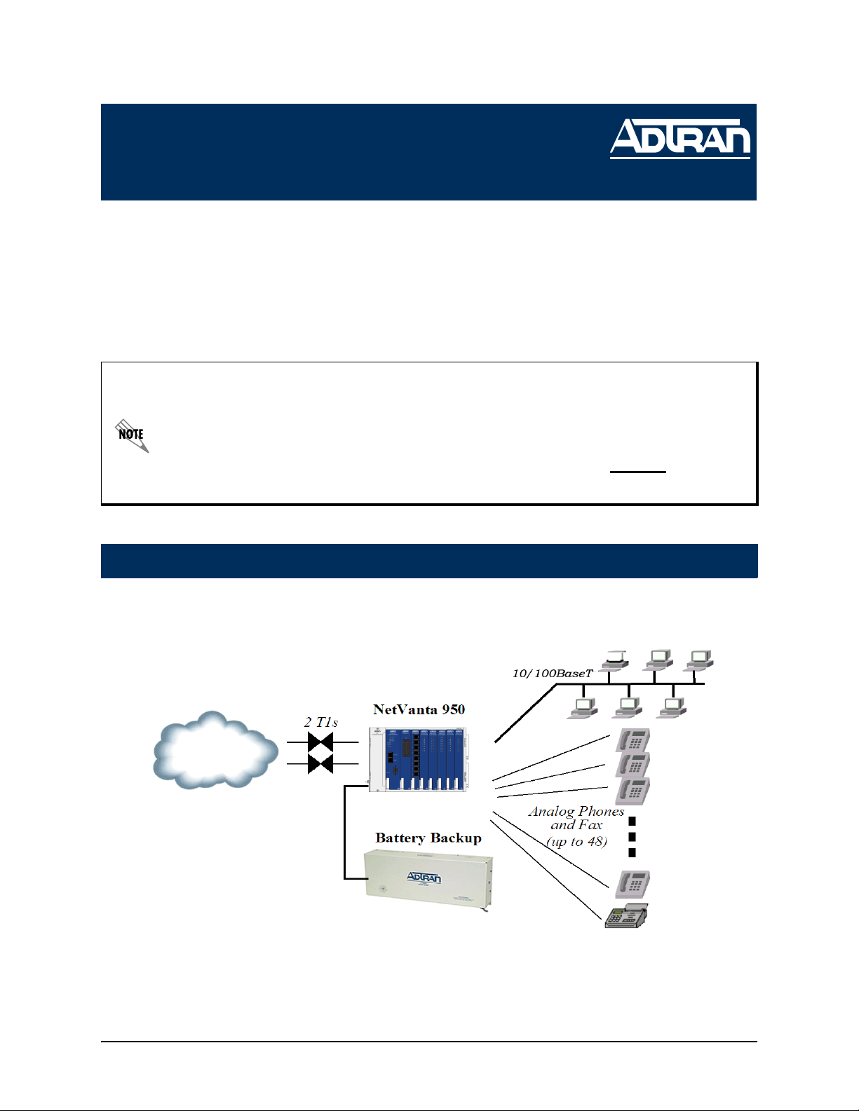
Network Diagram
Technical Support 1-888-4ADTRAN (1-888-423-8726)
Page 2

Connect to the NetVanta 950 IAD
You can access your NetVanta 950 IAD in two ways in order to configure it: (1) through the ADTRAN
Operating System Command Line Interface (AOS CLI), or (2) through the web-based GUI. The steps
below explain how to access you unit using these methods.
AOS CLI
The AOS CLI allows the user to access and control the system through a command driven CONSOLE connection. Users have more configuration control and advanced options available via this
type of connection.
1. Connect a VT100 terminal (or PC with VT100 emulation software) to the NetVanta
CONSOLE port on the front panel of your Controller Module using a DB-9 (male) to DB-9
(female) straight-through serial cable.
2. Connect the other end of the serial cable to the terminal or PDC.
3. Insert the connector of the provided power cord into the power interface on the rear panel of
the unit, and plug the cord into a standard electrical outlet.
4. Open a VT100 terminal session and configure the terminal’s COM port with the following
parameters:
Data Rate: 9600
Data Bits: 8
Parity Bits: None
Stop Bits: 1
Flow Control: None
5. Press the <Enter> key activate the ADTRAN operating system command line interface (AOS
CLI).
6. Enter enable at the > prompt.
7. Enter the password when prompted. The default password is password.
Web-Based GUI
The web-based GUI is an online configuration too that allows you to easily configure and view
the main setting and status of your system. However, use of the AOS CLI may be necessary for
more advanced configurations. Access the CLI via the CONSOLE port or a Telnet session. See
the AOS CLI section above.
1. Connect the unit to your network using on of the Ethernet ports on the faceplate of the
Controller module.
2. Enter the IP address in you Internet browser Address field.
2 Technical Support 1-888-4ADTRAN (1-888-423-8726) 64200788L1-13B
Page 3
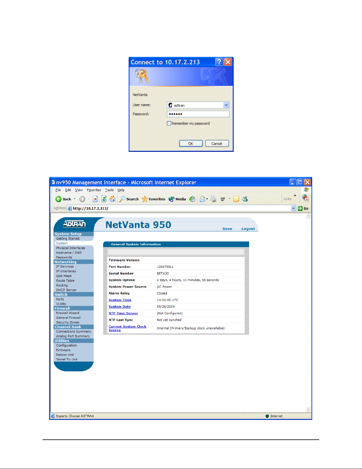
3. Once you are connected, you will be prompted to enter the username and password. The
default settings are adtran and adtran.
4. The initial GUI screen appears.
64200788L1-13B Technical Support 1-888-4ADTRAN (1-888-423-8726) 3
Page 4

Once you gain access to your unit via one of the methods described on pages 2 and 3, you can
configure it using the following guidelines.
Configure the Ethernet Interface
1. Enter enable to enter the Enable
command security mode.
2. Enter config terminal to enter the
Global configuration mode.
3. Enter enable password password
to
assign an Enable security mode
password. This is necessary for Telnet
configuration sessions (password
is an
example).
4. Enter interfac vlan 1 to access the
VLAN (virtual LAN) interface.
5. Enter ip address 10.26.12.12
255.255.255.0
to assign an IP address
to the Ethernet port using a 24-bit
subnet mask. Contact your Network
Administrator to obtain the IP address
(and subnet mask) for your particular
configuration.
6. Enter no shutdown to activate the
interface to pass data.
7. Enter interface eth 0/1 to access the
configuration parameters for the
Ethernet port.
! Begin Script
!
enable
!
config terminal
!
enable password password
!
interface vlan 1
!
ip address 10.26.12.12 255.255.255.0
!
no shutdown
!
interface eth 0/1
!
no shutdown
!
exit
!
ip route 0.0.0.0 0.0.0.0 192.22.72.2
! End Script
8. Enter no shutdown to activate the interface to pass data.
9. Enter exit to exit the interface commands and return to the Global configuration mode.
10. Enter ip route 0.0.0.0 0.0.0.0 192.22.72.2
to add a default route to the route table. Contact
you Network Administrator to obtain the IP address of your default gateway.
4 Technical Support 1-888-4ADTRAN (1-888-423-8726) 64200788L1-13B
Page 5

Configure a Telnet Session
1. Verify that the prompt of your unit displays IAD (config) #.
2. Enter line telnet 0 to activate the configuration parameters for the Telnet sessions.
3. Enter password password
to create a login password for the Telnet sessions.
4. Enter exit to return to the Global configuration mode.
Configure the Frame Relay Virtual Interface
The following steps outline configuring a frame relay virtual interface (labeled 1) using a single DLCI back
to the corporate router (defined as DLCI 16).
The following steps assume the Global configuration mode is currently active. Verify the
prompt of your unit displays (config)#.
Create the Interface and Define the Encapsulation
1. Enter interface fr 1 to create a
frame relay virtual interface
labeled 1.
2. Enter frame-relay lmi-type
ansi
to configure frame relay
virtual interface 1 to use ANSI
(Annex D) signaling. The default
LMI type is Cisco.
3. Enter no shutdown to activate
the interface to pass data.
4. Enter exit to return to the Global
configuration mode.
fr1.txt - Notepad
! This script creates a virtual frame relay interface labeled 1
! and defines ANSI (Annex D) as the signaling method. A
! text version of this script (fr1.txt) is available on the
! ADTRAN OS Documentation CD.
!
! First create the virtual frame relay interface and enter the
! configuration mode for the interface.
interface fr 1
!
! The prompt should now display (config-f1)#.
!
! Next assign the lmi type for the interface.
frame-relay lmi-type ansi
!
! Activate the interface to pass data.
no shutdown
!
! Exit back to the global configuration mode.
exit
!
! End script
64200788L1-13B Technical Support 1-888-4ADTRAN (1-888-423-8726) 5
Page 6

Create the PVC and Assign an IP Address
1. Enter interface fr 1.1 to create the first
PVC assigned to frame relay virtual
interface 1. This activates the
configuration parameters for the PVC.
Your prompt should now display IAD
(config-fr1.1)#.
2. Enter frame-relay interface-dlci 16 to
assign DLCI 16 to this PVC. (DLCIs
should be supplied by your network
provider.)
3. Enter ip address 192.22.72.1
255.255.255.0
to assign an IP address
of 192.22.72.1 for this PVC using a 24bit subnet mask.
4. Enter exit to return to the Global
configuration mode.
pvc16.txt - Notepad
! This script creates a pvc assigned to frame relay virtual
! interface 1 using DLCI 16. A text version of this script
! (pvc16.txt) is available on the ADTRAN OS
! Documentation CD.
!
! First create the first pvc assigned to frame relay
! virtual interface 1.
interface fr 1.1
!
! Your prompt should now display (config-fr1.16)#.
!
! Now assign DLCI 16 to the pvc.
frame-relay interface-dlci 16
!
! Next, assign an IP address to this pvc.
ip address 192.22.72.1 255.255.255.0
!
! Activate the interface to pass data.
no shutdown
!
! Exit back to the global configuration mode.
exit
!
! End script
6 Technical Support 1-888-4ADTRAN (1-888-423-8726) 64200788L1-13B
Page 7

Configure the Virtual PPP Interface
The following steps outline configuring a PPP Global configuration interface (labeled 1) to the
NetVanta 950 IAD.
The following steps assume the Global configuration mode is currently active. Verify the
prompt of the unit displays (config)#.
1. Enter the interface ppp 1 to create a
PPP virtual interface labeled 1.
2. Enter ip address 192.22.72.1
255.255.255.0
to assign an IP
address to the PPP endpoint using a
24-bit mask.
3. Enter no shutdown to activate the
interface to pass data.
4. Enter exit to return to the Global
configuration mode.
ppp1-IP.txt - Notepad
This script configures the virtual PPP endpoint labeled 1
! with an IP address. A text version of this script
! (ppp1-IP.txt) is available on the ADTRAN OS
! Documentation CD.
!
! First activate the PPP interface configuration mode.
interface ppp 1
!
! This activates the configuration parameters for this
! interface. Your prompt should now display
! (config-ppp1)#.
!
! Next, assign an IP address using a 24 bit mask.
ip address 192.22.72.1 255.255.255.0
!
! Activate the interface to pass data.
no shutdown
!
!Exit back to the global configuration mode
exit
!
!End script
64200788L1-13B Technical Support 1-888-4ADTRAN (1-888-423-8726) 7
Page 8

Create a T1 to Virtual Interface Cross-Connect
For this example we will configure a T1 WAN interface with DS0s 1-10 for data. The following
steps assume the Global configuration mode is currently active. Verify that the prompt of your
unit displays (config)#.
1. Enter interface t1 0/1 to activate the
interface configuration mode for the
T1 WAN interface.
2. Enter tdm-group 1 timeslots 1-10 to
create a TDM group for DS0s 1-10
(the data DS0s) on the T1 network
connection (t1 0/1).
3. Enter no shutdown to activate the
interface to pass data.
4. Enter exit to return to the Global
configuration mode.
5. Enter cross-connect 1 t1 0/1 1
frame-relay 1 to connect DS0s 1-10
of the T1 network connection (t1 0/1)
to the virtual frame-relay interface fr
1.16.
Alternately,
6. Enter cross-connect 1 t1 0/1 1 ppp
1 to connect DS0s 1-10 of the T1
network connection (t1 0/1) to the
virtual PPP interface labeled 1.
t1-x-fr.txt - Notepad
! This script creates a connection between a T1
! interface and a virtual interface. A text version
! of this script (t1-x-fr.txt) is available on the
! Adtran OS Documentation CD.
!
! First activate the first T1 interface configuration mode.
interface t1 0/1
!
! Your prompt should now display
! (config-t1 0/1)#.
!
! Create a TDM group on this T1 interface
tdm-group 1 timeslots 1-10 speed 64
!
! Activate the interface to pass data.
no shutdown
!
! Exit back to the global configuration mode
exit
!
! Connect the TDM Group on T1 0/1 to the virtual frame
! relay interface
cross-connect 1 t1 0/1 1 frame-relay 1
!
! Alternately, the cross-connect could be used to connect
! to the virtual PPP interface.
cross-connect 1 t1 0/1 1 ppp 1
!
! End script
8 Technical Support 1-888-4ADTRAN (1-888-423-8726) 64200788L1-13B
Page 9

Create a T1 to FXS Cross-Connect
For this example we will map DS0 1 from T1 WAN 0/1 to FXS 2/1. The NetVanta 950 IAD
Octal FXS access module (1200791L1) must be installed for this application to work. The
following steps assume the Global configuration mode is currently active. Verify that the
prompt of your unit displays (config)#.
1. Enter interface fxs 2/1 to access the
configuration parameters for the FXO
interface.
2. Enter no shutdown to activate the
voice interface.
3. Enter interface t1 0/1 to access the
configuration parameters for the
WAN 0/1 interface.
4. Enter tdm-group 1 timeslots 1 to
create a TDM group for DS0 1 on the
T1 network t1 0/1 at.
5. Enter exit to return to Global
configuration mode.
6. Enter cross-connect 1 t1 0/1 1.1 fxs
2/1 to connect DS0 2 of the T1
network to the FXS port (fxs 2/1).
t1-x-fxs.txt - Notepad
!This script configures the cross-connect T1 WAN
! connection (t1 0/1) to the FXS interface. A text version of
! this script (t1-x-fxs.txt) is available on the ADTRAN OS
! Documentation CD.
! Mapping DS0 1 from T1 0/1 to FXS 2/1
interface fxs 2/1
!
no shutdown
!
interface t1 0/1
!
tdm-group 1 timeslots 1
!
exit
!
cross-connect 1 t1 0/1 1.1 fxs 2/1
!
!End script
64200788L1-13B Technical Support 1-888-4ADTRAN (1-888-423-8726) 9
Page 10

Create a T1 to FXO Cross-Connect
For this example we will map DS0 2 from T1 WAN 0/1 to FXO 4/1. The NetVanta 950 IAD
Octal FXO access module (1200792L1) must be installed for this application to work. The
following steps assume the Global configuration mode is currently active. Verify that the
prompt of your unit displays (config)#.
1. Enter interface fxo 4/1 to access the
configuration parameters for the FXO
interface.
2. Enter no shutdown to activate the
voice interface.
3. Enter interface t1 0/1 to access the
configuration parameters for the
WAN 0/1 interface.
4. Enter tdm-group 1 timeslots 2
speed 64 to create a TDM group for
DS0 2 on the T1 network t1 0/1 at 64
kbps.
5. Enter exit to return to Global
configuration mode.
6. Enter cross-connect 1 t1 0/1 1.2 fxo
4/1 to connect DS0 2 of the T1
network to the FXO port (4/1).
t1-x-fxs.txt - Notepad
!This script configures the cross-connect T1 WAN
! connection (t1 0/1) to the FXS interface. A text version of
! this script (t1-x-fxo.txt) is available on the ADTRAN OS
! Documentation CD.
! Mapping DS0 2 from T1 0/1 to FXS 4/1
interface fxs 4/1
!
no shutdown
!
interface t1 0/1
!
tdm-group 1 timeslots 2
!
exit
!
cross-connect 1 t1 0/1 1.2 fxs 4/1
!
!End script
10 Technical Support 1-888-4ADTRAN (1-888-423-8726) 64200788L1-13B
Page 11

Create a T1 to Serial Cross-Connect
For this example we will map DS0s 1-12 from T1 WAN 0/1 to Serial 1/1. The NetVanta 950
IAD T1/V.35 Expansion Module (1200798L1) must be installed for this application to work.
The following steps assume the Global configuration mode is currently active. Verify that the
prompt of your unit displays (config)#.
1. Enter interface serial 1/1 to access
the configuration parameters for the
serial interface.
2. Enter no shutdown to activate the
serial interface.
3. Enter config terminal to enter the
Global configuration mode.
4. Enter interface t1 0/1 to access the
configuration parameters for the
WAN 0/1 interface.
5. Enter tdm-group 1 timeslots 1-12
speed 64 to create a TDM group for
DS0 1-12 on the T1 network (t1 0/1)
at the speed of 64 kbps for each
DS0.
6. Enter exit to return to Global
configuration mode.
7. Enter cross-connect 1 t1 0/1 1 ser
1/1 to connect DS0 1-12 of the T1
network to the serial 1/1 (V.35)
interface.
t1-x-ser.txt - Notepad
! This script configures the cross-connect for the T1 WAN
! connection (t1 0/1) to the Serial Interface (1/1). A text
! version of this script (t1-x-ser.txt) is available on the
! ADTRAN OS Documentation CD.
!Mapping 12 channels from WAN 0/1 to Serial 1/1
interface serial 1/1
!
no shutdown
!
interface t1 0/1
!
tdm-group 1 timeslots 1-12 speed 64
!
exit
!
cross-connect 1 t1 0/1 1 ser 1/1
!
! End Script
64200788L1-13B Technical Support 1-888-4ADTRAN (1-888-423-8726) 11
Page 12

Create a T1 to T1 Cross-Connect
For this example we will map DS0s 1-12 from T1 WAN 0/1 to T1 1/1. The NetVanta 950 IAD
T1/V.35 Expansion module (1200798L1) must be installed for this application to work.
1. Enter interface t1 0/1 to access the
configuration parameters for the
WAN 0/1 interface.
2. Enter tdm-group 1 timeslots 1-12
speed 64 to create a TDM group for
DS0s 1-12 on the T1 network (t1 0/1)
at the speed of 64 kbps for each
DS0.
3. Enter exit to return to Global
configuration mode.
4. Enter interface t1 1/1 to access the
configuration parameters for the T1
interface (t1 1/1).
5. Enter tdm group 2 timeslots 1-12
speed 64 to create a TDM group for
DS0s 1-12 on the Expansion Slot T1
interface at a speed of 64 kbps for
each DS0.
6. Enter cross-connect 1 t1 0/1 1 t1
1/1 2 rbs to connect DS0s 1-12 of
the T1 network to the Expansion Slot
T1 interface (rbs is optional and is
used when doing robbed-bitsignaling with voice applications).
t1-x-t1.txt - Notepad
This script creates a TDM connection between two T1
! interfaces for digital voice. A text version of this
! script (t1-x-t1.txt) is available on the Adtran OS
! Documentation CD.
! First activate the first T1 interface configuration mode.
interface t1 0/1
!
! This activates the configuration parameters for this
! interface. Your prompt should now display
! IAD(config-t1 0/1)#.
!
! Create a TDM group on this T1 interface
tdm-group 1 timeslots 1-12
!
! Activate the interface to pass data.
no shutdown
!
! Activate the second T1 interface configuration mode.
interface t1 1/1
!
! Create a TDM group on this T1 interface
tdm-group 2 timeslots 1-12
!
! Activate the interface to pass data.
no shutdown
!
! Exit back to the global configuration mode
exit
! Connect TDM Group on T1 0/1 to TDM Group onT1 1/1
Save the Configuration
1. Verify that the prompt of your unit displays IAD#.
2. Enter copy running-config startup-config to save the current configuration to memory.
3. Enter exit to close the configuration session.
12 Technical Support 1-888-4ADTRAN (1-888-423-8726) 64200788L1-13B
 Loading...