

Page 1
NetVanta Series
(with 56K/64K Network Interface Module)
Quick Configuration Guide
64200861L1-42A February 2004
Equipment Required
• Category 5 - UTP cable for connecting the system to the existing network.
• VT100 terminal or PC with VT100 emulation software.
• DB-9 (male) to DB-9 (female) straight-through serial cable for configuring the unit.
This quick start guide provides step-by-step instructions for configuring your application. The
configuration scripts are available on the ADTRAN OS System Documentation CD.
The configuration parameters used in the example outlined in this document are for
instructional purposes only. Please replace all underlined entries (example
parameters to configure your application
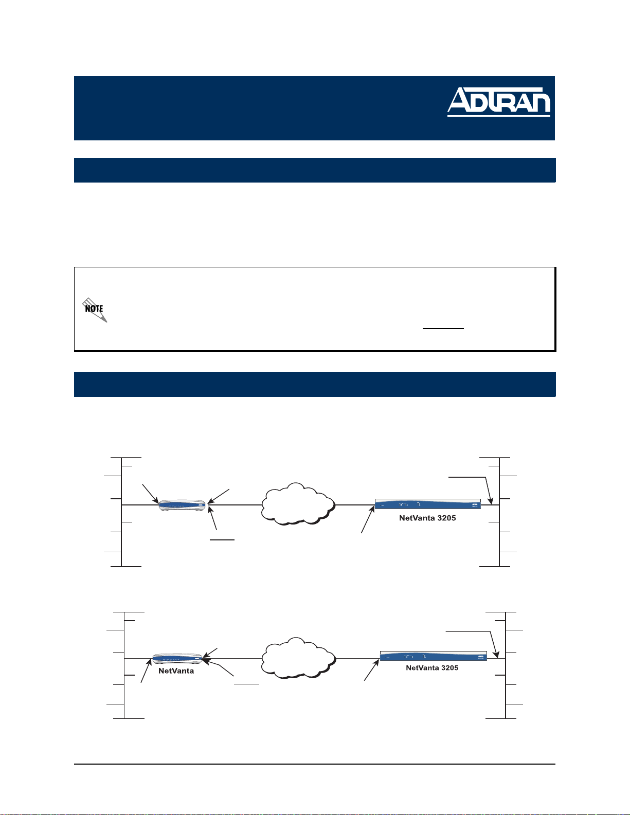
Network Diagrams
Frame-Relay over DDS Connection Diagram
) with your specific
Branch Office Corporate HQ
eth 0/1
LAN IP:
10.10.20.7/24
NetVanta 3200
WAN LAN
WAN LAN
VPN
VPN
PWR
PWR
RD
RD
STAT
STAT
TD
TD
RD
TD
TD
TD
RD
RD
NetVanta
FR 1
DLCI 16
Annex D Signaling
192.168.72.1/30
PPP over DDS Connection Diagram
Branch Office Corporate HQ
dds 1/1
NetVanta 3200
VPN
VPN
WAN LAN
WAN LAN
PWR
PWR
RD
RD
STAT
STAT
TD
TD
RD
TD
TD
TD
RD
RD
eth 0/1
10.10.20.7/24
LAN IP:
dds 1/1
Frame Relay
DDS Network
PPP 1
PPP Signaling
192.168.72.1/30
LAN IP: 10.10.10.1/24
WAN IP: 192.168.72.2/30
LAN IP: 10.10.10.1/24
WAN IP: 192.168.72.2/30
Technical Support 1-888-4ADTRAN (1-888-423-8726)
Page 2

Configuring the Unit
1
The NetVanta may be initially accessed and managed either via a console session or
through a Telnet session. See step 1a for console session instructions. Initiating a Telnet session requires using a hub and two Ethernet cables (one for the PC and one for
the unit). The default Ethernet IP address is 10.10.10.1. Refer to step 9 to change Telnet session settings.
1a
Initiating a Console Session
1. Connect a VT100 terminal (or PC with VT100 emulation software) to the NetVanta
CONSOLE port using a DB-9 (male) to DB-9 (female) straight-through serial cable.
2. Configure the COM port with the following parameters:
Data Rate: 9600
Data Bits: 8
Parity Bits: None
Stop Bits: 1
Flow Control: None
3. Open a VT100 terminal session. (Please refer to the appropriate VT100 terminal
software documentation for detailed instructions.)
4. Press the <Enter> key.
5. Enter enable at the > prompt.
6. Enter the password when prompted. The default password is password.
7. You are now at the # prompt. At the # prompt, enter config terminal to enter the
global configuration mode.
2 Technical Support 1-888-4ADTRAN (1-888-423-8726) 64200861L1-42A
Page 3
Configuring the Ethernet Port Parameters
2
1. At the (config)# prompt, enter interface eth 0/1 to access the configuration
parameters for the Ethernet port located on the rear panel of the unit.
2. Enter ip address 10.10.20.7
255.255.255.0 to assign an IP address to the
Ethernet port using a 24-bit subnet mask.
If you are accessing the NetVanta via Telnet, once you change this IP address, you will
lose connection to the NetVanta. You must change the IP address of your PC before you
can proceed.
ADTRAN recommends that you set the Ethernet speed and duplex to match the switch or
hub it is plugged in to.
For example: (config-eth 0/1)#speed 10
(config-eth 0/1)#half-duplex
3. Enter no shutdown to activate the interface to pass data.
4. Enter exit to exit the Ethernet interface commands and return to the global
configuration mode.
The NetVanta Network Interface Modules (NIMs) use a slot/port notation for interface
identification. All non-modular interfaces built into the base unit (e.g., the Ethernet port) are
identified using 0 as the slot number.
Configuring the DDS Network Interface
3
The following steps demonstrate configuring a 56K or 64K DDS network connection.
1. At the (config)# prompt, enter interface dds 1/1 to activate the interface
configuration mode for the DDS network interface.
2. Enter clock source line
to configure the unit to recover clocking from the DDS
network connection.
3. Enter clock rate bps56k to configure the interface for 56K service, or enter clock
rate bps64k for 64K service.
4. Enter no shutdown to activate the interface to pass data.
5. Enter exit to return to the global configuration mode.
Skip to step 6 for PPP configuration.
64200861L1-42A Technical Support 1-888-4ADTRAN (1-888-423-8726) 3
Page 4
Configuring the Frame-Relay Virtual Interface
4
The following steps outline configuring a frame-relay virtual interface (labeled 1) using
a single DLCI back to the corporate router (defined as DLCI 16).
1. At the (config)# prompt, enter interface fr 1 to create a frame-relay virtual
interface labeled 1.
2. If the default setting of ansi was changed, enter frame-relay lmi-type ansi to
configure frame-relay virtual interface 1 to use ANSI (Annex D) signaling.
3. Enter no shutdown to activate the virtual interface to pass data.
4. Enter exit to return to the global configuration mode.
5. The unit has a factory default PPP 1 interface. Enter the command no ppp 1 to
remove this interface.
Creating the PVC and Assigning an IP Address
5
1. At the (config)# prompt, enter interface fr 1.16 to create a PVC assigned to frame-
relay virtual interface 1. This activates the configuration parameters for the PVC.
Your prompt should now display (config-fr 1.16)#.
2. Enter frame-relay interface-dlci 16
3. Enter ip address 192.168.72.1
192.168.72.1 for this PVC using a 30-bit subnet mask.
4. Enter exit to return to the global configuration mode.
5. If you are configuring the NetVanta for use in a frame-relay application and have
completed this step, skip to step 7.
to assign DLCI 16 to this PVC.
255.255.255.252 to assign an IP address of
The default encapsulation is RFC 1490 or IETF. Make certain the remote unit uses the same
encapsulation for frame-relay.
Configuring the Virtual PPP Interface
6
The following steps show how to configure a PPP virtual interface (labeled 1) to the
corporate router. Skip to step 7 if you are using frame-relay.
1. At the (config)# prompt, enter interface ppp 1 to create a PPP virtual interface
labeled 1.
2. Enter ip address 192.168.72.1
PPP endpoint using a 30-bit mask.
3. Enter no shutdown to activate the virtual interface to pass data.
4. Enter exit to return to the global configuration mode.
255.255.255.252 to assign an IP address to the
4 Technical Support 1-888-4ADTRAN (1-888-423-8726) 64200861L1-42A
Page 5

Creating the Cross-Connect
7
1. For frame-relay applications, at the (config)# prompt, enter cross-connect 1 dds
1/1 frame-relay 1
frame-relay interface (fr 1.16).
or,
to connect the DDS network connection (dds 1/1) to the virtual
2. For PPP applications, enter cross-connect 1
network connection (dds 1/1) to the virtual PPP interface (ppp 1).
Configuring the Routes
8
Depending on your network setup, configure your unit in one of the following ways
beginning at the (config)# prompt:
Scenario 1: Static Route to the Far Side/Internet Access at Local Site
1. Set up the static route: ip route 10.10.10.0
(or frame-relay 1.16).
2. Set up the default route: ip route 0.0.0.0 0.0.0.0 10.10.20.x
internet router).
Scenario 2: No Internet Access at Local Site
1. Set up the default route: ip route 0.0.0.0 0.0.0.0 ppp 1 (or frame-relay 1.16).
2. The internet router at the far side will need a route statement to send traffic back to
this network through the NetVanta 3205. The information (based on the diagram
shown at the beginning of this document) is as follows:
dds 1/1 ppp 1 to connect the DDS
255.255.255.0 ppp 1
(i.e., address of
• Destination address: 10.10.20.0 (remote LAN)
• Subnet mask: 255.255.255.0
• Gateway: 10.10.10.1 (NetVanta 3205’s Ethernet)
64200861L1-42A Technical Support 1-888-4ADTRAN (1-888-423-8726) 5
Page 6
Configuring Telnet
9
The following steps show how to access the Telnet configuration parameters and
change the password. The default password for initializing a Telnet session is
password (all lower-case). For security purposes, change the password to something
unique. For this example, replace the underlined word
choosing. The NetVanta supports five Telnet sessions (0-4).
1. Verify that the prompt of your unit displays (config)#.
2. Enter line telnet 0 4 to change the configuration parameters for the Telnet session.
3. Enter password word
4. Enter exit to return to the global configuration mode.
An enable security mode password must be defined before configured Telnet sessions are
activated. See the following step (Step 10) for information on password configuration.
to change the login password for the Telnet session.
with a password of your
10
11
Setting the Enable Security Mode Password
1. Verify that the prompt of your unit displays (config)#.
2. Enter enable password word
or
3. Enter enable password md5 word
encryption.
The enable command security level passwords are case sensitive.
to set the enable security mode password.
to encrypt the enable password using MD5
Saving the Configuration
1. Verify that the prompt of your unit displays (config)#.
2. Enter exit to leave configuration mode.
3. Enter copy running-config startup-config to save the current configuration to
memory. This command may be abbreviated as copy run start.
4. Enter exit to close the configuration session.
12
6 Technical Support 1-888-4ADTRAN (1-888-423-8726) 64200861L1-42A
Completing the Installation
The NetVanta is now configured and operational. Complete the installation by connecting the appropriate cables to the DDS and Ethernet networks. Please refer to the
NetVanta Hardware Installation Guide for more details on pinouts and cabling.
 Loading...