

Page 1

NetVanta 340 Series Hardware Installation Guide
1200422L1 NetVanta 340 Unit
61200422L1-34A
November 2004
Page 2

Trademarks NetVanta 340 Series Hardware Installation Guide
Trademarks
Any brand names and product names included in this manual are trademarks, registered trademarks, or
trade names of their respective holders.
To the Holder of the Manual
The contents of this manual are current as of th e date of publication. ADTRAN reserves the right to change
the contents without prior notice.
In no event will ADTRAN be liable for any special, incidental, or consequential damages or for
commercial losses even if ADTRAN has been advised thereof as a result of issue of this publication.
901 Explorer Boulevard
P.O. Box 140000
Huntsville, AL 35814-4000
Phone: (256) 963-8000
© 2004 ADTRAN, Inc.
All Rights Reserved.
Printed in U.S.A.
2 © 2004 ADTRAN, Inc. 61200422L1-34A
Page 3
NetVanta 340 Series Hardware Installation Guide Conventions
Conventions
Notes provide additional useful information.
Cautions signify information that could prevent service interruption.
Warnings provide information that could prevent damage to the equipment or
endangerment to human life.
61200422L1-34A © 2004 ADTRAN, Inc. 3
Page 4
Safety Instructions NetVanta 340 Series Hardware Installation Guide
Safety Instructions
When using your telephone equipment, please follow these basic safety precautions to reduce the risk of
fire, electrical shock, or personal injury:
1. Do not use this product near water, such as a bathtub, wash bowl, kitchen sink, laundry tub, in a
wet basement, or near a swimming pool.
2. Avoid using a telephone (other than a cordless-type) during an electrical storm. There is a remote
risk of shock from lightning.
3. Do not use the telephone to report a gas leak in the vicinity of the leak.
4. Use only the power cord, power supply, and/or batteries indicated in the manual. Do not dispose of
batteries in a fire. They may explode. Check with local codes for special disposal instructions.
5. The socket-outlet shall be installed near the equipment and shall be easily accessible.
This equipment incorporates double pole/neutral fusing. If the neutral fuse opens and the
line fuse does not open, voltage could still be present in the unit.
Save These Important Safety Instructions
Changes or modifications to this unit not expressly approved by the party
responsible for compliance could void the user’s authority to operate the equipment.
4 © 2004 ADTRAN, Inc. 61200422L1-34A
Page 5

NetVanta 340 Series Hardware Installation Guide FCC-Required Information
FCC-Required Information
FCC regulations require that the following information be provided in this manual:
1. This equipment complies with Part 68 of FCC rules and requirements adopted by ACTA. Each
registered interface has a label that contains, among other information, a product identifier in the
format US:AAAEQ##TXXXX. If requested, provide this information to the telephone company.
2. If this equipment causes harm to the telephone network, the telephone company may temporarily
discontinue service. If possible, advance notification is given; otherwise, notification is given as
soon as possible. The telephone company will advise the customer of the right to file a complaint
with the FCC.
3. The telephone company may make changes in its facilities, equipment, operations, or procedures
that could effect the proper operation of this equipment. Advance notification and the opportunity
to maintain uninterrupted service are given.
4. If experiencing difficulty with this equipment, please contact ADTRAN for repair and warranty
information. The telephone company may require this equipment to be disconnected from the
network until the problem is corrected or it is certain the equipment is not malfunctioning.
5. This unit contains no user-serviceable parts.
6. This equipment is designed to connect to the telephone network or premises wiring using an FCCcompatible modular jack, which is compliant with Part 68 and requirements adopted by ACTA.
7. The following information may be required when applying to the local telephone company for
leased line facilities:
Registration
Part Number
1200422L1 US: HDCDL01A1200422L1 ADSL 0.1A/9.0F 02LS2 RJ-11C
Number Service Type REN/SOC FIC USOC
8. The REN is useful in determining the quantity of devices you may connect to your telephone line
and still have all of those devices ring when your number is called. In most areas, the sum of the
RENs of all devices should not exceed five. To be certain of the number of devices you may
connect to your line as determined by the REN, call your telephone company to determine the
maximum REN for your calling area.
9. This equipment may not be used on coin service provided by the telephone company. Connection
to party lines is subject to state tariffs. Contact your state public utility commission or corporation
commission for information.
61200422L1-34A © 2004 ADTRAN, Inc. 5
Page 6

FCC Radio Frequency Interference Statement NetVanta 340 Series Hardware Installation Guide
FCC Radio Frequency Interference Statement
This equipment has been tested and found to comply with the limits for a Class B digital device, pursuant
to Part 15 of the FCC Rules. These limits are designed to provide reasonable protection against harmful
interference in a residential installation. This equipment generates, uses, and can radiate radio frequency
energy and, if not installed and used in accordance with the instruction manual, may cause harmful
interference to radio communications. However , there is no guarantee that interference will not occur in a
particular installation. If this equipment does cause harmful interference to radio or television reception,
which can be determined by turning the equipment off and on, the user is encouraged to try to correct the
interference by one or more of the following measures:
• Reorient or relocate the receiving antenna.
• Increase the separation between the equipment and receiver.
• Connect the equipment into an outlet on a circuit different from that to which the receiver is connected.
• Consult the dealer or an experienced radio/TV technician for help.
Changes or modifications to this unit not expressly approved by the party
responsible for compliance could void the user’s authority to operate the
equipment.
6 © 2004 ADTRAN, Inc. 61200422L1-34A
Page 7

NetVanta 340 Series Hardware Installation Guide Industry Canada Compliance Information
Industry Canada Compliance Information
The Industry Canada label applied to the product (identified by the Industry Canada logo or the “IC:” in
front of the certification/registration number) signifies that the Industry Canada technical specifications
were met.
The Ringer Equivalence Number (REN) for this terminal equipment is supplied in the documentation or on
the product labeling/markings. The REN assigned to each terminal device indicates the maximum number
of terminals that can be connected to a telephone interface. The termination on an interface may consist of
any combination of devices subject only to the requirement that the sum of the RENs of all the devices
should not exceed five (5).
Canadian Emissions Requirements
This digital apparatus does not exceed the Class B limits for radio noise emissions from digital apparatus
as set out in the interference-causing equipment standard entitled “Digital Apparatus,” ICES-003 of the
Department of Communications.
Cet appareil numérique respecte les limites de bruits radioelectriques applicables aux appareils numériques
de Class A prescrites dans la norme sur le materiel brouilleur: “Appareils Numériques,” NMB-003 edictee
par le ministre des Communications.
61200422L1-34A © 2004 ADTRAN, Inc. 7
Page 8

Warranty and Customer Service NetVanta 340 Series Hardware Installation Guide
Warranty and Customer Service
ADTRAN will repair and return this product within the warranty period if it does not meet its published
specifications or fails while in service. Warranty information can be found at: http://support.adtran.com
(Click on Warranty and Repair Information, under Support.).
Product Registration
Registering your product helps ensure complete customer satisfaction. Please take time to register your
products on line at http://support.adtran.com
. Click on Service/Support and then on Product Registration
under Support.
Product Support Information
A return material authorization (RMA) is required prior to returning equipment to ADTRAN. For service,
RMA requests, training, or more information, use the following contact information:
Repair and Return
If you determine that a repair is needed, please contact our Customer and Product Service (CaPS)
department to have an RMA number issued. CaPS should also be contacted to obtain information
regarding equipment currently in house or possible fees associated with repair.
CaPS Department (256) 963-8722
Identify the RMA number clearly on the package (below address), and return to the following address:
ADTRAN Customer and Product Service
901 Explorer Blvd. (East Tower)
Huntsville, Alabama 35806
RMA # _____________
8 © 2004 ADTRAN, Inc. 61200422L1-34A
Page 9

NetVanta 340 Series Hardware Installation Guide Product Support Information
Pre-Sales Inquiries and Applications Support
Your reseller should serve as the first point of contact for support. If additional pre-sales support is needed,
the ADTRAN Support web site provides a variety of support services such as a searchable knowledge
base, latest product documentation, application briefs, case studies, and a link to submit a question to an
Applications Engineer. All of this, and more, is available at:
http://support.adtran.com
When needed, further pre-sales assistance is available by calling our Applications Engineering
Department.
Applications Engineering (800) 615-1176
Post-Sale Support
Your reseller should serve as the first point of contact for support. If additional support is needed, the
ADTRAN Support web site provides a variety of support services such as a searcha ble knowledge base,
updated firmware releases, latest product documentation, service request ticket generation and troubleshooting tools. All of this, and more, is available at:
http://support.adtran.com
When needed, further post-sales assistance is available by calling our Technical Support Center. Please
have your unit serial number available when you call.
Technical Support (888) 4ADTRAN
International Technical Support 1-256-963-8716
Installation and Maintenance Support
The ADTRAN Custom Extended Services (ACES) program offers multiple types and levels of installation
and maintenance services which allow you to choose the kind of assistance you need. This support is
available at:
http://support.adtran.com
For questions, call the ACES Help Desk.
ACES Help Desk (888) 874-ACES (2237)
61200422L1-34A © 2004 ADTRAN, Inc. 9
Page 10

Product Support Information NetVanta 340 Series Hardware Installation Guide
Training
The Enterprise Network (EN) T echnical T raining Department offers training on our most po pular products.
These courses include overviews on product features and functions while covering applications of
ADTRAN's product lines. ADTRAN provides a variety of training options, including customized training
and courses taught at our facilities or at your site. For more information about training, please contact your
Territory Manager or the Enterprise Training Coordinator.
Training Phone (800) 615-1176, ext. 7500
Training Fax (256) 963-6700
Training Email training@adtran.com
10 © 2004 ADTRAN, Inc. 61200422L1-34A
Page 11

Table of Contents
Introduction to the NetVanta Solution. . . . . . . . . . . . . . . . . . . . . . . . . . . . . . . . . . . . . . . . . . . . . . . . . . 17
Features and Specifications . . . . . . . . . . . . . . . . . . . . . . . . . . . . . . . . . . . . . . . . . . . . . . . . . . . . . . . . 17
Unpack and Inspect the System . . . . . . . . . . . . . . . . . . . . . . . . . . . . . . . . . . . . . . . . . . . . . . . . . . . . . 19
Contents of ADTRAN Shipments . . . . . . . . . . . . . . . . . . . . . . . . . . . . . . . . . . . . . . . . . . . . . . . . . 19
Physical Description . . . . . . . . . . . . . . . . . . . . . . . . . . . . . . . . . . . . . . . . . . . . . . . . . . . . . . . . . . . . . . . . 20
Reviewing the Base Unit Front Panel Design. . . . . . . . . . . . . . . . . . . . . . . . . . . . . . . . . . . . . . . . . . . 20
Front Panel LEDs . . . . . . . . . . . . . . . . . . . . . . . . . . . . . . . . . . . . . . . . . . . . . . . . . . . . . . . . . . . . . 20
Reviewing the Rear Panel Design . . . . . . . . . . . . . . . . . . . . . . . . . . . . . . . . . . . . . . . . . . . . . . . . . . . 21
Rear Panel Interfaces and LEDs . . . . . . . . . . . . . . . . . . . . . . . . . . . . . . . . . . . . . . . . . . . . . . . . . 21
Unit Installation . . . . . . . . . . . . . . . . . . . . . . . . . . . . . . . . . . . . . . . . . . . . . . . . . . . . . . . . . . . . . . . . . . . . 22
Mounting Options . . . . . . . . . . . . . . . . . . . . . . . . . . . . . . . . . . . . . . . . . . . . . . . . . . . . . . . . . . . . . . . . 22
Wall Mounting. . . . . . . . . . . . . . . . . . . . . . . . . . . . . . . . . . . . . . . . . . . . . . . . . . . . . . . . . . . . . . . . 23
Getting Started . . . . . . . . . . . . . . . . . . . . . . . . . . . . . . . . . . . . . . . . . . . . . . . . . . . . . . . . . . . . . . . . . . 24
Connect to the NetVanta 340 . . . . . . . . . . . . . . . . . . . . . . . . . . . . . . . . . . . . . . . . . . . . . . . . . . . . 24
Configure the ATM PVC. . . . . . . . . . . . . . . . . . . . . . . . . . . . . . . . . . . . . . . . . . . . . . . . . . . . . . . . 24
Factory Default Switch . . . . . . . . . . . . . . . . . . . . . . . . . . . . . . . . . . . . . . . . . . . . . . . . . . . . . . . . . 25
Appendix A. Connector Pin Definitions . . . . . . . . . . . . . . . . . . . . . . . . . . . . . . . . . . . . . . . . . . . . . . . . 27
Index. . . . . . . . . . . . . . . . . . . . . . . . . . . . . . . . . . . . . . . . . . . . . . . . . . . . . . . . . . . . . . . . . . . . . . . . . . . . . 29
61200422L1-34A © 2004 ADTRAN, Inc. 11
Page 12

Table of Contents NetVanta 340 Series Hardware Installation Guide
12 © 2004 ADTRAN, Inc. 61200422L1-34A
Page 13

List of Figures
Figure 1. NetVanta 340 Front Panel Layout . . . . . . . . . . . . . . . . . . . . . . . . . . . . . . . . . . . . . . . . . . . . . 20
Figure 2. NetVanta 340 Rear Panel Layout . . . . . . . . . . . . . . . . . . . . . . . . . . . . . . . . . . . . . . . . . . . . . 21
Figure 3. Wall Mounting the NetVanta 340 . . . . . . . . . . . . . . . . . . . . . . . . . . . . . . . . . . . . . . . . . . . . . . 23
61200422L1-34A © 2004 ADTRAN, Inc. 13
Page 14

List of Figures NetVanta 340 Series Hardware Installation Guide
14 © 2004 ADTRAN, Inc. 61200422L1-34A
Page 15

List of Tables
Table 1. Features and Specifications . . . . . . . . . . . . . . . . . . . . . . . . . . . . . . . . . . . . . . . . . . . . . . . . 17
Table 2. NetVanta 340 LEDs . . . . . . . . . . . . . . . . . . . . . . . . . . . . . . . . . . . . . . . . . . . . . . . . . . . . . . 20
Table A-1. ADSL Connector Pinouts . . . . . . . . . . . . . . . . . . . . . . . . . . . . . . . . . . . . . . . . . . . . . . . . . . 27
Table A-2. 10/100BaseT Ethernet Port Pinouts . . . . . . . . . . . . . . . . . . . . . . . . . . . . . . . . . . . . . . . . . . 27
61200422L1-34A © 2004 ADTRAN, Inc. 15
Page 16

List of Tables NetVanta 340 Series Hardware Installation Guide
16 © 2004 ADTRAN, Inc. 61200422L1-34A
Page 17

1. INTRODUCTION TO THE NETVANTA SOLUTION
The NetVanta 340 is an ATM router designed for cost-effective branch office connectivity over frame relay
or point-to-point (PPP) networks. This product is designed for small- to medium-sized business customers.
This unit comes equipped with a 10/100BaseT Ethernet LAN interface and an ADSL network interface.
Features and Specifications
The following table highlights the major features of the NetVanta 340.
Table 1. Features and Specifications
Layer 2 protocol: ATM
Routed protocol: IP
Learning bridge functionality
Protocol Support
10/100BaseT RJ-48C
ADSL Interface
ATM Specific Support
Static routes
RIP v1/v2
802.1d bridging with spanning tree
LLC-SNAP and VC-MUX (null) encapsulation over AAL5
RJ-11
ITU G.992.1 (G.dmt) Annex A, ITU G.992.2 (G.lite), ITU G.992.3 (G.dmt.bis),
ITU G.992.4 (G.lite.bis), ITU G.992.5 (Adsl 2+)
ANSI T1.413 Issue 2
Extended reach (ER-ADSL)
Dynamic rate adaptation
Bit swapping
Dying gasp
AAL5 support for at least 16 PVCs
RFC 2364 support -- PPP over AAL5 (LLC and VC muxing)
RFC 2684 support -- Multi-protocol over ATM
PPPoE Relay and PPPoE Client (RFC 2516)
I.610 F4/F5 OAM loopback support
Full support of ATM WAN statistics
Stateful Inspection Firewall
Firewall
DHCP/DNS Support DHCP Client, DHCP Server, DNS Proxy
61200422L1-34A © 2004 ADTRAN, Inc. 17
Cyber assault protection
Denial of Service (DoS) protection
Page 18

Introduction to the NetVanta Solution NetVanta 340 Series Hardware Installation Guide
Table 1. Features and Specifications (Continued)
Familiar Command Line Interface (CLI)
Web configuration interface (HTTP, HTTPS)
Telnet
Management
Routing Protocol OSPF, RIP, BGP, and Static
Routed Protocol
PPP
WAN Protocol ATM
Quality of Service
(QoS)
Optional Virtual
Private Network (VPN)
SNMP
SYSLOG logging
RADIUS authentication
Secure Shell (SSH) management
Policy statistics
IP
Bridging (other protocols)
LCP, IPCP, BCP
Disaster recovery
Priority and Weighted Fair Queuing (WFQ)
DiffServ packet marking and recognition
IPSec Mode: Tunnel
Encryption: DES, 3DES, and AES
Diffie Hellman Group Support: Group 1 - MODP 768; Group 2 - MODP 1024
Has Algorithms: MD5-HMAC, SHA1-HMAC
Authentication mechanisms: XAUTH, digital certificates,preshared keys
Key management: IKE (ISAKMP/Oakley)
IKE modes: Main, Aggressive
Environmental
Physical
Agency Approvals
Operating temperature: 0° to 40°C; humidity 8% to 100%, noncondensing
Storage/Transport temperature: -20° to 85°C; humidity 5% to 100%
Dimensions: 7.5 inches W x 1.75 inches H x 5.375 inches D
Weight: 0.8 lb
Power: 120 VAC, 60 Hz, 65 mA, double insulated
FCC Part 15, Class B; ACTA/FCC Part 68, UL 60950
Industry Canada CS-03, CNA/CSA C.22.2, No. 60950
This hardware installation guide describes the NetVanta 340, details basic functionality, gives installation
instructions, and lists unit specifications. For more information on router configuration for a specific
application, refer to the quick configuration documents provided on the ADTRAN website at
www .adtran.com. For details on the command line interfa ce, refer to the AOS Command Reference Guide,
also on the website.
18 © 2004 ADTRAN, Inc. 61200422L1-34A
Page 19

NetVanta 340 Series Hardware Installation Guide Introduction to the NetVanta Solution
Unpack and Inspect the System
Each NetVanta 340 unit is shipped in its own cardboard shipping carton. Open each carton carefully, and
avoid deep penetration into the carton with sharp objects.
After unpacking the unit, inspect it for possible shipping damage. If the equipment has been damaged in
transit, immediately file a claim with the carrier and contact ADTRAN Customer Service (see W arranty
and Customer Service on page 8).
Contents of ADTRAN Shipments
Shipments of the NetVanta 340 include the following items:
• NetVanta 340 Base Unit
• NetVanta 340 Quick Start Guide
• NetVanta 340 power cable (black)
• NetVanta 340 phone cable (silver)
• NetVanta 340 Ethernet cable (yellow)
61200422L1-34A © 2004 ADTRAN, Inc. 19
Page 20
Physical Description NetVanta 340 Series Hardware Installation Guide
2. PHYSICAL DESCRIPTION
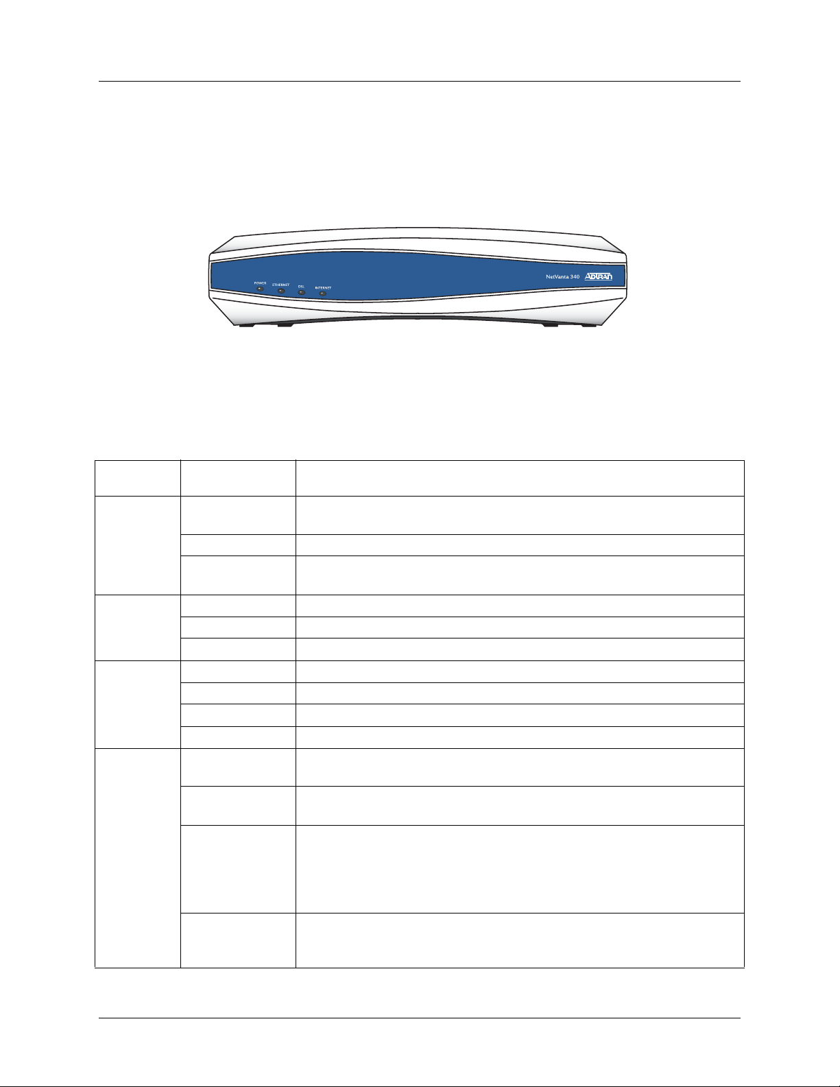
Reviewing the Base Unit Front Panel Design
Figure 1 shows the NetVanta 340 front panel.
Figure 1. NetVanta 340 Front Panel Layout
Front Panel LEDs
Table 2 describes the front panel LEDs.
Table 2. NetVanta 340 LEDs
For this
LED…
Power
Ethernet Gree n (fla sh in g) LAN activity is present (traffic in either direction).
DSL Off Modem power is off.
Internet
This activity… Indicates that…
Green (flashing)
Green (solid) Power is on and self-test passed.
Red (solid)
Green (solid) Powered device is connected to the Ethernet port (i.e., link integrity).
Off There is no LAN activity on the Ethernet port (or modem is powered off).
Green (flashing) Attempting DSL sync.
Green (solid) DSL link is up and everything is operational.
Red (solid) DSL connection failure.
Off
Green (flashing)
Green (solid)
Red (solid)
Unit is powering up. On power-up the Power LED flashes rapidl y for five
seconds, during which time the user may escape to boot mode.
Power is on, but the self-test failed or the boot mode (if applicable) code
could not be booted.
Modem power is off, modem is in bridged mode, or ADSL connection is
not present.
IP connected and IP traffic is passing through the device (in either
direction).
IP connected (the device has a WAN IP address from IPCP or DHCP
and DSL connection is up) and no traffic is detected. If the IP or PPPoE
session is dropped, the light remains green if an ADSL connection is still
present. Light turns red when it attempts to reconnect and DHCP or
PPPoE fails.
Modem attempted to become IP connected and failed (no DHCP
response, no PPPoE response, PPPoE authentication failed, no IP
address from IPCP, etc.).
20 © 2004 ADTRAN, Inc. 61200422L1-34A
Page 21
NetVanta 340 Series Hardware Installation Guide Physical Description
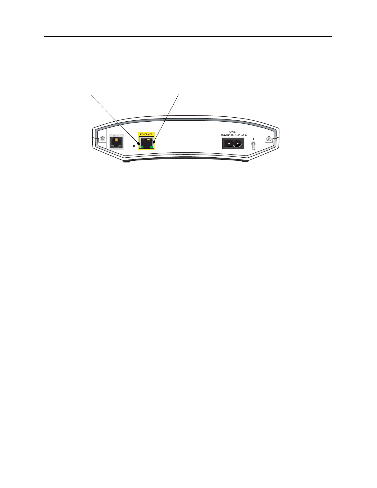
Reviewing the Rear Panel Design
Figure 2 shows the NetVa nta 340 rear panel. The Activity and Link LEDs, which are present on all
NetVanta Ethernet ports, are pointed out.
Link LED (green)
Figure 2. NetVanta 340 Rear Panel Layout
Activity LED (amber)
Rear Panel Interfaces and LEDs
ADSL Interface
The ADSL port is an RJ-11 conn ector. See T able A-1 on page 27 for the ADSL port pinout. The ADSL
port provides the following:
• ITU G.992.1 (G.dmt) Annex A
• ITU G.992.2 (G.lite)
• ITU G.992.3 (G.dmt.bis)
• ITU G.992.4 (G.lite.bis)
• ITU G.992.5 (Adsl2+)
• ANSI T1.413 Issue 2
• Extended Reach (ER-ADSL)
• Dynamic Rate Adaptation
• Bit Swapping
• Dying Gasp
10/100BaseT Ethernet Interface and Activity LEDs
The ETHERNET port is an RJ-48C connector with LEDs. The yellow activity LED flashes when data
traffic is being sent or received on the Ethernet port. The green link LED is on when the unit has a
good connection to the LAN. See Table A-2 on page 27 for the Ethernet port pinout. The Ethernet port
provides the following:
• 10BaseT or 100BaseT with a single connector
• Auto-negotiation
•CSMA/CD
• IEEE 802.3 compatibility
• Auto MDI/MDIX
61200422L1-34A © 2004 ADTRAN, Inc. 21
Page 22

Unit Installation NetVanta 340 Series Hardware Installation Guide
3. UNIT INSTALLATION
The instructions and guidelines provided in this section cover hardware installation topics such as wall
mounting and supplying power to the unit.
To prevent electrical shock, do not install equipment in a wet location or during a
lightning storm.
Mounting Options
The NetVanta 340 may be installed in a wallmount or tabletop configuration. The following section
provides step-by-step instructions for wall mounting.
22 © 2004 ADTRAN, Inc. 61200422L1-34A
Page 23

NetVanta 340 Series Hardware Installation Guide Unit Installation
Wall Mounting
Instructions for Wall Mounting
Step Action
1 Decide on a location for the NetVanta 340. Keep in mind that the unit need s to be mounted at or
below eye-level so that the LEDs are viewable.
2 Prepare the mounting surface by attaching a boar d (typically plywood, 3/ 4" to 1" thick) to a wall
stud.
Important! Mounting to a stud ensures stability. Using sheetrock anchors may not provide
sufficient long-term stability.
3 Install two #8 PAN headscrews (1 1/ 2" or greater in length) wood screws into the mounted
board, following these guidelines and referring to Figure 3:
• Screws should be spaced horizontally, approximately 5 inches apart. Find exact positioning
by using the location of the two eyed insets on the bottom of the NetVanta 340 as a guide.
• Screws should be horizontally level with each other.
• Leave approximately 1/4 inch of the screws protruding from the board to allow the heads of
the screws to slide into place in the unit’s keyed insets.
4 Slide the keyed insets on the bottom of the NetVanta 340 chassis securely onto the screws.
5 Proceed to the steps given in Getting Started on page 24.
S
T
A
T
W
A
N
D
B
U
T
D
Figure 3. Wall Mounting the NetVanta 340
61200422L1-34A © 2004 ADTRAN, Inc. 23
Page 24

Unit Installation NetVanta 340 Series Hardware Installation Guide
Getting Started
The 10/100BaseT Ethernet interface MUST NOT be metallically connected to
interfaces which connect to the Outside Plant or its wiring. This interface is designed
for use as an intrabuilding interface only. The addition of primary protectors is not
sufficient protection in order to connect this interface metallically to OSP wiring.
Connect to the NetVanta 340
1. Connect the NetVanta 340 ETHERNET interface to the PC using the appropriate Ethernet cable.
2. Supply power to the PC and the NetVanta 340 and begin the operating system boot up process.
During boot up, the PC obtains an IP address from the NetVanta 340 DHCP server. By default,
both the DHCP and HTTP servers are enabled. The default IP address is 10.10.10.1.
3. Open your internet browser and enter 10.10.10.1. in the URL field. The NetVanta 340 login
window appears.
4. Enter the default username (admin) and password (adtran), and click the OK button.
For security purposes, you should set up an admin password immediately. Use the
Passwords page of the Web GUI to change this password.
5. By default, the NetVanta 340 comes with an ADSL and an ATM (Asynchronous Transfer Mode)
port already configured and enabled. The service provider should provide a PVC (VPI / VCI)
number which will be used to configure the ATM PVC.
Configure the ATM PVC
1. Click on the Getting Started link under the System menu. This will bring up a side bar page.
2. Click on
PVC page.
3. Fill in the PVC number and select an
IP routing is chosen, you will need to enter an IP address.
4. Click
after clicking
passwords, and the
Negotiated. Click Apply when all the information is complete.
Step 1 - Configure the Public Interf ace at the top of the side bar page to open the ATM
Interface Mode. This is usually PPP or PPPoE; however, if
Apply. If PPP or PPPoE is selected as the Interface Mode, you will be taken to the PPP page
Apply. Here you will need to select the type of authentication needed, authentication
Address Type. In most cases you will want the Address Type to be
24 © 2004 ADTRAN, Inc. 61200422L1-34A
Page 25
NetVanta 340 Series Hardware Installation Guide Unit Installation
Factory Default Switch
• If pressed during bootup, the default switch will cause the unit to stay in bootstrap mode. Since the unit
has no serial port, Telnet has been built into the boot code. The default IP address is 10.10.10.1.
The default switch must be pressed WHILE the power light is flashing gr een. Do not pr ess
the default switch BEFORE the power light is flashing green, as this will cause boot to be
missed.
• If pressed and held for 5 seconds after boot, the
ETHERNET interface will default to 10.10.10.1, and all
access policies will be removed from that interface.
• If pressed for 30 seconds, a default configuration will overwrite your existing configuration and reboot
the unit.
Maximum recommended ambient operating tempera t ure is 50°C.
To prevent electrical shock, do not install equipment in a wet location or during a
lightning storm.
61200422L1-34A © 2004 ADTRAN, Inc. 25
Page 26

Unit Installation NetVanta 340 Series Hardware Installation Guide
26 © 2004 ADTRAN, Inc. 61200422L1-34A
Page 27

APPENDIX A. CONNECTOR PIN DEFINITIONS
The following tables provide the pin assignments for the NetVanta 340.
Table A-1. ADSL Connector Pinouts
Pin Name Description
1-2 — Unused
3T ADSL Tip
4R ADSL Ring
5-6 — Unused
Table A-2. 10/100BaseT Ethernet Port Pinouts
Pin Name Description
1 TX1 Transmit Positive
2 TX2 Transmit Negative
3 RX1 Receive Positive
6 RX2 Receive Negative
4, 5, 7, 8 — Unused
61200422L1-34A © 2004 ADTRAN, Inc. 27
Page 28

Appendix A. Connector Pin Definitions NetVanta 340 Series Hardware Installation Guide
28 © 2004 ADTRAN, Inc. 61200422L1-34A
Page 29

Index
Numerics
10/100BaseT Ethernet interface 21
pinout
27
A
admin password 24
ADSL interface
pinout
ATM PVC
configuring
21
27
24
B
boot up 24
C
configuring ATM PVC 24
connecting to unit
contents of shipment
24
19
D
default switch 25
F
factory default switch 25
features of NetVanta 340
front panel
LEDs
20
20
17
M
mounting options 22
N
NetVanta 340
connecting to
default switch
features
front panel
getting started
installation
interfaces
LEDs
20, 21
mounting options
physical description
rear panel
unpacking and inspecting the system
wall mounting
24
25
17
20
24
22
21
22
20
21
23
P
passwords page 24
pinouts
10/100BaseT
ADSL
product registration
27
27
8
R
rear panel 21
19
G
getting started 24
I
installing unit 22
interfaces
21
L
LEDs 20, 21
61200422L1-34A © 2004 ADTRAN, Inc. 29
S
shipping contents 19
U
unpacking and inspecting the system 19
W
wall mounting NetVanta 340 23
warranty
web GUI
8
passwords page
24
Page 30

Index NetVanta 340 Series Hardware Installation Guide
30 © 2004 ADTRAN, Inc. 61200422L1-34A
 Loading...