

Page 1
TECHNICAL SUPPORT NOTE
NetVanta 3000 Series Routers
Bridging (Point-to-Point & Multipoint)
_____________________________________________________________________________________
Introduction
Bridging is an OSI Model Layer 2 function. Bridges and switches are often talked about
interchangeably because both of these devices work at the Data Link Layer. Bridges are a step
above a network device called a hub. A hub operates at the Physical Layer, connecting one or
more network devices on the LAN, sharing bandwidth or acting as a termination point for multiple
network devices in a star topology. A bridge is a LAN (Local Bridge) or WAN (Remote Bridge)
device that interconnects network segments and uses the destination MAC address of each frame
of information to determine whether to pass the signal to the other network segment. Bridges can
be used to connect network segments of dissimilar media, extend the number of hosts allowed on
a single segment, or segment data traffic to reduce overall bandwidth usage.
A bridge keeps a forwarding table, which is a list of MAC (or Layer 2) addresses with their
associated interface. If the bridge does not have an entry for a destination address that comes
across, the packet is forwarded to all attached interfaces. All broadcast and multicast packets are
forwarded to all interfaces (flooded).
Care should be used in deciding when to use a bridge. In general, it is only wise to bridge data
that cannot be routed. The NetVanta 3000 Router can route IP while bridging all other protocols.
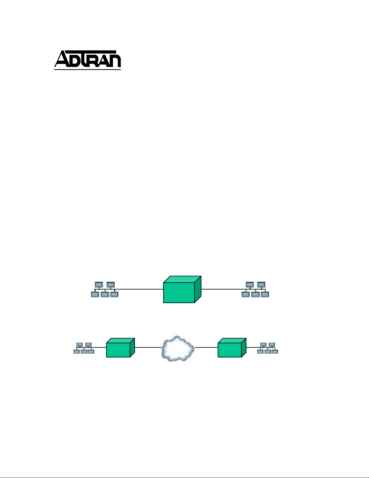
Local Bridge
Remote Bridge – Like the Net Vant as
☛
☛ Before You Begin
☛☛
Before configuring and testing a bridging application, verify that the point-to-point network
connection is installed and operational. All cables necessary for network connection installation
Page 2
Bridging: NetVanta 3000 Series Routers
are provided with your NetVanta shipment. Obtain the correct IP Addresses for the Ethernet
interfaces from your network administrator before configuring this application. Generally, the
Ethernet interfaces on all units will need to be on the same subnet for bridging applications.
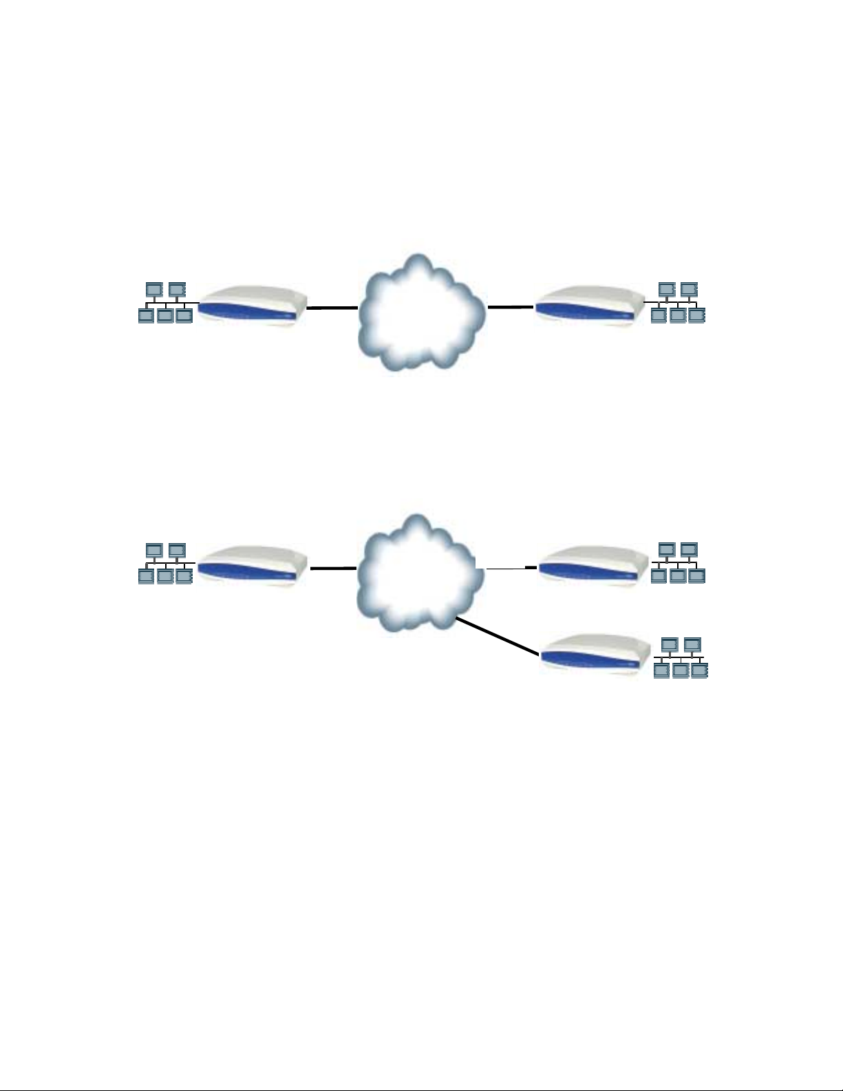
The first example details a simple point-to-point bridge configured using PPP as the WAN
protocol. The second example demonstrates the NetVanta router configuration for multipoint
bridging over frame relay.
Denver
T1
T1
Atlanta
TELCO
PPP Point-to-Point Bridging Example
Denver
T1
T1
Frame
T1
Frame Relay Multipoint Bridging example
Atlanta
Albany
Page 2
Page 3

Bridging: NetVanta 3000 Series Routers
Configuring Point-to-Point Bridging
Log into the router via the craft port and enter the enable (privileged) mode by typing enable and
entering the password (if enable passwords are configured). Next, enter the global configuration
mode by typing config t . From the global configuration mode, enter the bridge command and
specify a bridge group number. (The valid range for a bridge group number is 1 through 255.)
Specify the protocol for the bridge group at the end of the command. The bridging protocol must
match the protocol used on the remote NetVanta or compatible router. In this example, the bridge
group 1 is being configured to use the IEEE bridging protocol.
Router(config)# bridge 1 protocol ieee
Bridge Command Example Syntax
Configuring Bridge Interfaces
1. All interfaces that are involved in the bridging process (WAN & LAN) must belong to the
appropriate bridge group. (Refer to the previous section, Configuring Point-to-Point Bridging,
for details on creating a bridge group.) Include an interface in the bridge group by using the
bridge command while in the interface configuration mode. To enter the interface
configuration mode, enter interface <interface type interface slot/port> from the global
configuration prompt. For example, interface eth 0/1.
Router(config-eth 0/1)# bridge-group 1
SPANNING TREE: Using default Address 00:A0:C8:08:CA:EE.
Please ensure this is unique.
Assigning Ethernet 0/1 Interface to Bridge Group 1
2. The bridge command must be used on the sub-interface to configure bridging interfaces on
WAN ports implementing Frame Relay signaling. Enter the sub-interface configuration mode
by typing interface frame relay X.Y from the global configuration mode prompt (where X is the
frame relay interface number and Y is the sub-interface – usually the DLCI – number). For
example, interface frame-relay 1.16. For PPP, the virtual interface must be included in the
bridge group (e.g., interface ppp 1).
Router(config-fr 1.16)# bridge-group 1
SPANNING TREE: Using default Address 00:A0:C8:08:CA:EE.
Please ensure this is unique.
Assigning a Frame Relay Sub-Interface to Bridge Group 1
Page 3
Page 4

Bridging: NetVanta 3000 Series Routers
Router(config-ppp 1)# bridge-group 1
SPANNING TREE: Using default Address 00:A0:C8:08:CA:EE.
Please ensure this is unique.
Assigning a PPP Sub-Interface to Bridge Group 1
3. If you are bridging and do not wish to route IP, IP routing should be disabled. Enter no ip
routing at the global configuration mode prompt to disable IP routing for all interfaces on the
router. For simple bridging applications (IP traffic is routed and all other protocols are
bridged), IP routing is not disabled and the unit must be properly configured for routing ( the
remote ip address must be on a unique subnet). Also the command bridge 1 route ip must
be issued in global configuration mode to allow IP routing and bridging of other protocols.
Router(config)# no ip routing
Disabling IP Routing
4. The complete configuration for the point-to-point PPP bridging application is shown below in
the format of a script:
no ip routing
!
interface eth 0/1
full-duplex
speed auto
ip address 192.168.4.1 255.255.255.0
bridge-group 1
bridge-group 1 spanning-disabled
no shutdown
!
interface ser 1/1
no shutdown
!
interface ppp 1
no shutdown
cross-connect 1 serial 1/1 ppp 1
!
bridge-group 1
bridge-group 1 spanning-disabled
!
exit
bridge 1 protocol ieee
end
PPP Point-Point Configuration Script
Page 4
Page 5

Bridging: NetVanta 3000 Series Routers
5. Frame-Relay Multipoint – Multipoint bridging applications are useful for two remote offices that
have small traffic requirements and need to access local office resources (desiring minimal
changes to the local and main office servers). If all resources are using NetBEUI protocol,
bridging is the only option. There are minimal differences when configuring point-to-point and
multipoint applications (including frame relay configuration and assigning all sub-interfaces
(PVCs) to the bridge group). The complete configuration for multipoint bridging is shown
below and is annotated to highlight the differences from the point-to-point application.
no ip routing
!
interface eth 0/1
full-duplex
speed auto
ip address 192.168.4.1 255.255.255.0
bridge-group 1
bridge-group 1 spanning-disabled
no shutdown
!
interface ser 1/1
no shutdown
!
interface bri 1/2
shutdown
!
! Note that a frame relay virtual interface is created
interface fr 1 point-to-point
no shutdown
cross-connect 1 ser 1/1 frame-relay 1
!
! Here are the two sub-interfaces to the remote locations
interface fr 1.16 point-to-point
frame-relay interface-dlci 16
no ip address
bridge-group 1
bridge-group 1 spanning-disabled
!
interface fr 1.17 point-to-point
frame-relay interface-dlci 17
no ip address
bridge-group 1
bridge-group 1 spanning-disabled
bridge 1 protocol ieee
Frame Relay Multipoint Bridging Configuration
Page 5
Page 6

Bridging: NetVanta 3000 Series Routers
Troubleshooting the Application
If workstations at one end of the link cannot access workstations on the other end, use the
following tools to help determine the cause:
• Use the show interface (T1 1/1, or DDS 1/1, or Serial 1/1) command to display
information regarding the state of the physical layer.
• Link Layer:
show frame pvc – This command displays whether the frame relay virtual interface is
active, inactive, or deleted.
Router#sh fr pvc
Frame Relay Virtual Circuit Statistics for interface FR 1
local 1001
DLCI = 16, DLCI USAGE = LOCAL , PVC STATUS = ACTIVE, INTERFACE = FR 1.16
MTU: 1500
input pkts: 10 output pkts: 10 in bytes: 1000
out bytes: 1000 dropped pkts: 0 in FECN pkts: 0
in BECN pkts: 0 in DE pkts: 0 out DE pkts: 0
pvc create time: 00:00:00:15 last time pvc status changed:
00:00:00:47
show ppp 1 – Shows the state of the PPP connection.
Router# sho int ppp 1
ppp 1
Link state is OPENED
Internet address is 192.168.1.1, Mask is 255.255.255.0
Far end internet address is 192.168.1.2
MTU is unknown
BW 1544 Kbit
Keepalive set (10 sec)
Authentication protocol is NONE
OPEN: LCP, IPCP
CLOSED: Bridge
8 packets input, 134 bytes
Received 8 broadcasts
0 input errors, 0 discards
9 packets output, 162 bytes
0 output errors, 0 discards
• show bridge 1 – This command gives the current state of the bridge group and the
forwarded addresses.
When troubleshooting any network problem, it is essential to work through all layers of the OSI
model beginning with the physical layer. For bridging applications, verify that the interface and link
layer protocol are functioning properly before troubleshooting the bridging configuration.
Active Inactive Deleted Static
Page 6
Page 7

Bridging: NetVanta 3000 Series Routers
Completing the Application
Configure the remote end NetVanta 3000 Series Router similarly to the local site, with only one
frame relay sub-interface for the multipoint application. The remote PPP site is similar to the local
site shown previously. Both the local and remote NetVanta 3000 Series Routers will have distinct
host addresses assigned to the respective Ethernet ports, and they will be in the same subnet.
If you experience any problems using your ADTRAN product, please contact ADTRAN Technical
Support (1.888.4ADTRAN or 1.256.963.8716).
DISCLAIMER
ADTRAN provides the foregoing application description solely for the reader's consideration and
study, and without any representation or suggestion that the foregoing application is or may be free
from claims of third parties for infringement of intellectual property rights, including but not limited to,
direct and contributory infringement as well as for active inducement to infringe. In addition, the
reader's attention is drawn to the following disclaimer with regard to the reader's use of the foregoing
material in products and/or systems. That is:
ADTRAN SPECIFICALLY DISCLAIMS ALL WARRANTIES, EXPRESSED OR IMPLIED, INCLUDING
BUT NOT LIMITED TO, MERCHANTABILITY AND FITNESS FOR A PARTICULAR PURPOSE. IN
NO EVENT SHALL ADTRAN BE LIABLE FOR ANY LOSS OR DAMAGE, AND FOR PERSONAL
INJURY, INCLUDING BUT NOT LIMITED TO, COMPENSATORY, SPECIAL, INCIDENTAL,
CONSEQUENTIAL, OR OTHER DAMAGES.
Page 7
 Loading...