

Page 1

NETVANTA 2000 SERIES
System Manual
1200362L1 NetVanta 2050 System
1200361L1 NetVanta 2100 System
1200366L1 NetVanta 2300 System
1200367L1 NetVanta 2400 System
61200361L1-1E
May 2002
Page 2

Trademarks
Any brand names and product names included in this manual are trademarks, registered trademarks, or
trade names of their respective holders.
To the Holder of the Manual
The contents of this manual are current as of the date of publication. ADTRAN reserves the right to change
the contents without prior notice.
In no event will ADTRAN be liable for any special, incidental, or consequential damages or for
commercial losses even if ADTRAN has been advised thereof as a result of issue of this publication.
901 Explorer Boulevard
P.O. Box 140000
Huntsville, AL 35814-4000
Phone: (256) 963-8000
©2001 ADTRAN, Inc.
All Rights Reserved.
Printed in U.S.A.
NetVanta 2000 Series System Manual © 2001 ADTRAN, Inc.
Page 3

About this Manual
This manual provides a complete description of the NetVanta 2000 series system and system software. The
purpose of this manual is to provide the technician, system administrator, and manager with general and
specific information related to the planning, installation, operation, and maintenance of the NetVanta 2000
series. This manual is arranged so that needed information can be quickly and easily found. The following
is an overview of the contents.
Section 1 System Description
Provides managers with an overview of the NetVanta 2000 series system.
Section 2 Engineering Guidelines
Provides information to assist network designers with incorporating the NetVanta 2000
series system into their networks.
Section 3 Network Turnup Procedure
Provides step-by-step instructions on how to install the NetVanta 2000 series unit,
determine the parameters for the system, install the network and option modules, and
power up the system.
Section 4 User Interface Guide
A reference guide listing all menu options contained in the NetVanta 2000 series.
Section 5 Detail Level Procedures
Provides the Provides the Detail Level Procedures to perform various unit functions
(upgrading firmware, telnet, etc). Level Procedures called out in Section 3.
Glossary and Acronyms
Gives definitions of terms and acronyms used in the manual.
Revision History
This is the 4th issue of this manual. Revisions include:
• NetVanta 2050 and 2400 additions
© 2001 ADTRAN, Inc. NetVanta 2000 Series System Manual
Page 4

Notes provide additional useful information.
Cautions signify information that could prevent service interruption.
Warnings provide information that could prevent damage to the equipment or
endangerment to human life.
Safety Instructions
When using your telephone equipment, please follow these basic safety precautions to reduce the risk of
fire, electrical shock, or personal injury:
1. Do not use this product near water, such as a bathtub, wash bowl, kitchen sink, laundry tub, in a
wet basement, or near a swimming pool.
2. Avoid using a telephone (other than a cordless-type) during an electrical storm. There is a remote
risk of shock from lightning.
3. Do not use the telephone to report a gas leak in the vicinity of the leak.
4. Use only the power cord, power supply, and/or batteries indicated in the manual. Do not dispose of
batteries in a fire. They may explode. Check with local codes for special disposal instructions.
Save These Important Safety Instructions
NetVanta 2000 Series System Manual © 2001 ADTRAN, Inc.
Page 5

Federal Communications Commission Radio Frequency Interference Statement
This equipment has been tested and found to comply with the limits for a Class A digital device, pursuant
to Part 15 of the FCC Rules. These limits are designed to provide reasonable protection against harmful
interference when the equipment is operated in a commercial environment. This equipment generates,
uses, and can radiate radio frequency energy and, if not installed and used in accordance with the
instruction manual, may cause harmful interference to radio frequencies. Operation of this equipment in a
residential area is likely to cause harmful interference in which case the user will be required to correct the
interference at his own expense.
Shielded cables must be used with this unit to ensure compliance with Class A FCC limits.
Changes or modifications to this unit not expressly approved by the party responsible
for compliance could void the user’s authority to operate the equipment.
Canadian Emissions Requirements
This digital apparatus does not exceed the Class A limits for radio noise emissions from digital apparatus
as set out in the interference-causing equipment standard entitled “Digital Apparatus,” ICES-003 of the
Department of Communications.
Cet appareil numérique respecte les limites de bruits radioelectriques applicables aux appareils numériques
de Class A prescrites dans la norme sur le materiel brouilleur: “Appareils Numériques,” NMB-003 edictee
par le ministre des Communications.
© 2001 ADTRAN, Inc. NetVanta 2000 Series System Manual
Page 6

Canadian Equipment Limitations
Notice: The Canadian Industry and Science Canada label identifies certified equipment. This certification
means that the equipment meets certain telecommunications network protective, operational, and safety
requirements. The Department does not guarantee the equipment will operate to the user’s satisfaction.
Before installing this equipment, users should ensure that it is permissible to be connected to the facilities
of the local telecommunications company. The equipment must also be installed using an acceptable
method of connection. In some cases, the company’s inside wiring associated with a single line individual
service may be extended by means of a certified connector assembly (telephone extension cord). The
customer should be aware that compliance with the above limitations may not prevent degradation of
service in some situations.
Repairs to certified equipment should be made by an authorized Canadian maintenance facility designated
by the supplier. Any repairs or alterations made by the user to this equipment, or equipment malfunctions,
may give the telecommunications company cause to request the user to disconnect the equipment.
Users should ensure for their own protection that the electrical ground connections of the power utility,
telephone lines and internal metallic water pipe system, if present, are connected together. This precaution
may be particularly important in rural areas.
Users should not attempt to make such connections themselves, but should contract the
appropriate electric inspection authority, or an electrician, as appropriate.
The Load Number (LN) assigned to each terminal device denotes the percentage of the total load to be
connected to a telephone loop which is used by the device, to prevent overloading. The termination on a
loop may consist of any combination of devices subject only to the requirement that the total of the Load
Numbers of all devices does not exceed 100.
NetVanta 2000 Series System Manual © 2001 ADTRAN, Inc.
Page 7

Warranty and Customer Service
ADTRAN will repair and return this product within five years from the date of shipment if it does not meet
its published specifications or fails while in service. For detailed warranty, repair, and return information
refer to the ADTRAN Equipment Warranty and Repair and Return Policy Procedure.
Return Material Authorization (RMA) is required prior to returning equipment to ADTRAN.
For service, RMA requests, or further information, contact one of the numbers listed at the end of this
section.
LIMITED PRODUCT WARRANTY
ADTRAN warrants that for five years from the date of shipment to Customer, all products manufactured
by ADTRAN will be free from defects in materials and workmanship. ADTRAN also warrants that
products will conform to the applicable specifications and drawings for such products, as contained in the
Product Manual or in ADTRAN's internal specifications and drawings for such products (which may or
may not be reflected in the Product Manual). This warranty only applies if Customer gives ADTRAN
written notice of defects during the warranty period. Upon such notice, ADTRAN will, at its option, either
repair or replace the defective item. If ADTRAN is unable, in a reasonable time, to repair or replace any
equipment to a condition as warranted, Customer is entitled to a full refund of the purchase price upon
return of the equipment to ADTRAN. This warranty applies only to the original purchaser and is not
transferable without ADTRAN's express written permission. This warranty becomes null and void if
Customer modifies or alters the equipment in any way, other than as specifically authorized by ADTRAN.
EXCEPT FOR THE LIMITED WARRANTY DESCRIBED ABOVE, THE FOREGOING
CONSTITUTES THE SOLE AND EXCLUSIVE REMEDY OF THE CUSTOMER AND THE
EXCLUSIVE LIABILITY OF ADTRAN AND IS IN LIEU OF ANY AND ALL OTHER WARRANTIES
(EXPRESSED OR IMPLIED). ADTRAN SPECIFICALLY DISCLAIMS ALL OTHER WARRANTIES,
INCLUDING (WITHOUT LIMITATION), ALL WARRANTIES OF MERCHANTABILITY AND
FITNESS FOR A PARTICULAR PURPOSE. SOME STATES DO NOT ALLOW THE EXCLUSION
OF IMPLIED WARRANTIES, SO THIS EXCLUSION MAY NOT APPLY TO CUSTOMER.
In no event will ADTRAN or its suppliers be liable to the Customer for any incidental, special, punitive,
exemplary or consequential damages experienced by either the Customer or a third party (including, but
not limited to, loss of data or information, loss of profits, or loss of use). ADTRAN is not liable for
damages for any cause whatsoever (whether based in contract, tort, or otherwise) in excess of the amount
paid for the item. Some states do not allow the limitation or exclusion of liability for incidental or
consequential damages, so the above limitation or exclusion may not apply to the Customer.
© 2001 ADTRAN, Inc. NetVanta 2000 Series System Manual
Page 8

Customer Service, Product Support Information, and Training
ADTRAN will repair and return this product if within five years from the date of shipment the product
does not meet its published specification or the product fails while in service.
A return material authorization (RMA) is required prior to returning equipment to ADTRAN. For service,
RMA requests, training, or more information, use the contact information given below.
Repair and Return
If you determine that a repair is needed, please contact our Customer and Product Service (CAPS)
department to have an RMA number issued. CAPS should also be contacted to obtain information
regarding equipment currently in house or possible fees associated with repair.
CAPS Department (256) 963-8722
Identify the RMA number clearly on the package (below address), and return to the following address:
ADTRAN Customer and Product Service
901 Explorer Blvd. (East Tower)
Huntsville, Alabama 35806
RMA # _____________
Pre-Sales Inquiries and Applications Support
Your reseller should serve as the first point of contact for support. If additional pre-sales support is needed,
the ADTRAN Support web site provides a variety of support services such as a searchable knowledge
base, latest product documentation, application briefs, case studies, and a link to submit a question to an
Applications Engineer. All of this, and more, is available at:
http://support.adtran.com
When needed, further pre-sales assistance is available by calling our Applications Engineering
Department.
Applications Engineering (800) 615-1176
NetVanta 2000 Series System Manual © 2001 ADTRAN, Inc.
Page 9

Post-Sale Support
Your reseller should serve as the first point of contact for support. If additional support is needed, the
ADTRAN Support web site provides a variety of support services such as a searchable knowledge base,
updated firmware releases, latest product documentation, service request ticket generation and
trouble-shooting tools. All of this, and more, is available at:
http://support.adtran.com
When needed, further post-sales assistance is available by calling our Technical Support Center. Please
have your unit serial number available when you call.
Technical Support (888) 4ADTRAN
Installation and Maintenance Support
The ADTRAN Custom Extended Services (ACES) program offers multiple types and levels of installation
and maintenance services which allow you to choose the kind of assistance you need. This support is
available at:
http://www.adtran.com/aces
For questions, call the ACES Help Desk.
ACES Help Desk (888) 874-ACES (2237)
Training
The Enterprise Network (EN) Technical Training Department offers training on our most popular products.
These courses include overviews on product features and functions while covering applications of
ADTRAN's product lines. ADTRAN provides a variety of training options, including customized training
and courses taught at our facilities or at your site. For more information about training, please contact your
Territory Manager or the Enterprise Training Coordinator.
Training Phone (800) 615-1176, ext. 7500
Training Fax (256) 963-6700
Training Email training@adtran.com
© 2001 ADTRAN, Inc. NetVanta 2000 Series System Manual
Page 10

NetVanta 2000 Series System Manual © 2001 ADTRAN, Inc.
Page 11

SYSTEM DESCRIPTION
CONTENTS
System Overview . . . . . . . . . . . . . . . . . . . . . . . . . . . . . . . . . . . . . . . . . . . . . . . . . . . . . . . . . . . . . . . 12
Features and Benefits . . . . . . . . . . . . . . . . . . . . . . . . . . . . . . . . . . . . . . . . . . . . . . . . . . . . . . . . . . . 13
Physical Interfaces . . . . . . . . . . . . . . . . . . . . . . . . . . . . . . . . . . . . . . . . . . . . . . . . . . . . . . . . . . . 13
Firewall Features. . . . . . . . . . . . . . . . . . . . . . . . . . . . . . . . . . . . . . . . . . . . . . . . . . . . . . . . . . . . . 13
Address Translation . . . . . . . . . . . . . . . . . . . . . . . . . . . . . . . . . . . . . . . . . . . . . . . . . . . . . . . . . . 13
IPSec Tunnel. . . . . . . . . . . . . . . . . . . . . . . . . . . . . . . . . . . . . . . . . . . . . . . . . . . . . . . . . . . . . . . . 13
Administration . . . . . . . . . . . . . . . . . . . . . . . . . . . . . . . . . . . . . . . . . . . . . . . . . . . . . . . . . . . . . . . 13
DHCP . . . . . . . . . . . . . . . . . . . . . . . . . . . . . . . . . . . . . . . . . . . . . . . . . . . . . . . . . . . . . . . . . . . . . 14
PPPoE. . . . . . . . . . . . . . . . . . . . . . . . . . . . . . . . . . . . . . . . . . . . . . . . . . . . . . . . . . . . . . . . . . . . . 14
Routing . . . . . . . . . . . . . . . . . . . . . . . . . . . . . . . . . . . . . . . . . . . . . . . . . . . . . . . . . . . . . . . . . . . . 14
61200361L1-1E © 2002 ADTRAN, Inc. 11
Page 12

Section 1, System Description NetVanta 2000 Series System Manual
1. SYSTEM OVERVIEW
The NetVanta 2000 series of VPN products include small to mid-range IPSec compliant gateways
providing all the necessary components required to secure an integrated VPN solution. Used primarily for
remote access and site-to-multisite connectivity, the NetVanta 2050 and NetVanta 2100 targets the
corporate branch office, the small office/home office (SOHO), as well as business-to-business
applications. As a branch office or mid-size host security gateway, the NetVanta 2300 provides the same
features as the NetVanta 2100 with an added DMZ port for public server access. For networks supporting a
large VPN network, the NetVanta 2400 is available to provide all necessary host site gateway functionality.
The NetVanta 2000 series provides several key security and data management features such as IPSec VPN
tunneling, stateful inspection firewall (providing cyber assault protection), authenticated remote user
access, and Network Address Translation. Adhering to IPSec standards (established and maintained by the
IETF) enables the NetVanta 2000 series to be interoperable with many other IPSec compliant gateways,
allowing for a multi-vendor VPN solution.
On a public infrastructure like the Internet, security is of the utmost importance. The NetVanta 2000 series
protect the corporate network against attacks with a built in firewall and provides data security through
encryption, authentication and key exchange. The NetVanta 2000 series employ a stateful inspection
firewall that protects an organization's network from common cyber attacks including TCP syn-flooding,
IP spoofing, ICMP redirect, land attacks, ping-of-death, and IP reassembly problems.
For encryption, the NetVanta 2000 series encrypt the data being sent out onto the network, using either the
Data Encryption Standard (DES) or 3DES encryption algorithms. Data integrity is ensured using MD5 or
SHA1 as it is transported across the public infrastructure. In addition, Internet Key Exchange (IKE) can be
used for user authentication supporting public and private keys or digital certificates, assuring that the
proper VPN tunnel is established and that the tunnel has not been redirected or compromised.
NetVanta 2000 series are Internet Protocol Security (IPSec) compliant devices that supports both ESP and
AH protocols and provides secure communication over potentially unsecure network components. Acting
as a security gateway, the NetVanta 2050 and 2100 can provide up to 10 private encryption communication
tunnels through the Internet with remote locations while the larger scale NetVanta 2300 offers support for
up to 100 private encryption tunnels. For networks requiring more than 100 tunnels, the NetVanta 2400
provides 1000 private encryption tunnels. The NetVanta 2000 series can also hide IP addresses from the
external world by performing Network Address Translation (NAT). The internal router allows multiple
users to share a VPN connection and can also direct incoming IP traffic.
A remote NetVanta 2000 series can easily be configured and managed using a standard web browser.
NetVanta 2000 series also have built-in alert and logging mechanisms for messaging and mail services.
This enables the unit to warn administrators about activities that are going on in the network by logging
them into a Syslog server or sending an email to the administrator.
Unlike a software implemented VPN solution, which depends on local CPU and memory performance to
implement encryption, the NetVanta 2000 series are standalone, hardware platforms that off-load the CPU
intensive encryption process. 3DES encryption significantly impacts CPU performance, possibly slowing
all the local processes on the computer. Since the NetVanta 2000 series offers dedicated processing
platforms to drive the encryption process, local computer performance is unaffected.
12 © 2002 ADTRAN, Inc. 61200361L1-1E
Page 13

NetVanta 2000 Series System Manual Section 1, System Description
2. FEATURES AND BENEFITS
The NetVanta 2000 series provide granular control over network access that includes maximum security,
data authenticity and privacy, and significant ease of use. The major features of the NetVanta 2000 series
are described below.
Physical Interfaces
• WAN: RJ-45 10/100 Auto-sensing ethernet interface
• LAN: RJ-45 10/100 Auto-sensing ethernet interface
• Serial Port: RS-232 for off-net configuration (NetVanta 2300 Only)
• DMZ: RJ-45 10/100 Auto-sensing ethernet interface
Firewall Features
• Stateful inspection firewall
• Application content filtering
• Cyber assault protection
• HTTP relay
Address Translation
• Basic NAT (1:1)
• NAPT (Many:1)
• Reverse NAT (translation of an inbound session’s destination IP address)
IPSec Tunnel
• Encapsulating Security Payload (ESP)
• Authentication Header (AH)
• Manual key management or automatic key management using Internet Key Exchange (IKE)
• X.509 certificate support
• MD5-HMAC 128-bit authentication algorithm
• SHA1-HMAC 160-bit authentication algorithm
• DES-CBC 56-bit encryption
• 3DES-CBC 168-bit encryption
Administration
• Web-based management
• Syslog logging in WELF format
• E-mail alerts (SMTP)
• User and group access control policies based on time-of-day
• User accounting policy statistics
61200361L1-1E © 2002 ADTRAN, Inc. 13
Page 14

Section 1, System Description NetVanta 2000 Series System Manual
DHCP
• Server (to manage IP addresses on local network)
• Client (to acquire the WAN-side IP address from service provider)
PPPoE
• Client (to acquire the WAN-side IP address from service provider)
Routing
•TCP/IP
• Static routes
• RIP (V1 and V2)
• RIP with Authentication
14 © 2002 ADTRAN, Inc. 61200361L1-1E
Page 15

ENGINEERING GUIDELINES
CONTENTS
Equipment Dimensions . . . . . . . . . . . . . . . . . . . . . . . . . . . . . . . . . . . . . . . . . . . . . . . . . . . . . . . . . . 16
Power Requirements . . . . . . . . . . . . . . . . . . . . . . . . . . . . . . . . . . . . . . . . . . . . . . . . . . . . . . . . . . . . 16
Reviewing the front Panel Design . . . . . . . . . . . . . . . . . . . . . . . . . . . . . . . . . . . . . . . . . . . . . . . . . . 16
Front Panel LEDs . . . . . . . . . . . . . . . . . . . . . . . . . . . . . . . . . . . . . . . . . . . . . . . . . . . . . . . . . . . . 17
Reviewing the Rear Panel Design . . . . . . . . . . . . . . . . . . . . . . . . . . . . . . . . . . . . . . . . . . . . . . . . . . 18
LAN Interface . . . . . . . . . . . . . . . . . . . . . . . . . . . . . . . . . . . . . . . . . . . . . . . . . . . . . . . . . . . . . . . 19
WAN Connection. . . . . . . . . . . . . . . . . . . . . . . . . . . . . . . . . . . . . . . . . . . . . . . . . . . . . . . . . . . . . 19
DMZ Connection (NetVanta 2300 Only) . . . . . . . . . . . . . . . . . . . . . . . . . . . . . . . . . . . . . . . . . . . 20
COM1 Interface. . . . . . . . . . . . . . . . . . . . . . . . . . . . . . . . . . . . . . . . . . . . . . . . . . . . . . . . . . . . . . 21
Power Connection. . . . . . . . . . . . . . . . . . . . . . . . . . . . . . . . . . . . . . . . . . . . . . . . . . . . . . . . . . . . 21
At-A-Glance Specifications . . . . . . . . . . . . . . . . . . . . . . . . . . . . . . . . . . . . . . . . . . . . . . . . . . . . . . . 22
FIGURES
Figure 1. NetVanta 2000 series Front Panel Layout . . . . . . . . . . . . . . . . . . . . . . . . . . . . . . . . . . . 16
Figure 2. NetVanta 2300 Front Panel Layout . . . . . . . . . . . . . . . . . . . . . . . . . . . . . . . . . . . . . . . . 17
Figure 3. NetVanta 2000 series Rear Panel Layout . . . . . . . . . . . . . . . . . . . . . . . . . . . . . . . . . . . 18
Figure 4. NetVanta 2300 Rear Panel Layout . . . . . . . . . . . . . . . . . . . . . . . . . . . . . . . . . . . . . . . . 19
TABLES
Table 1. NetVanta 2000 series Front Panel Description . . . . . . . . . . . . . . . . . . . . . . . . . . . . . . . . 17
Table 2. NetVanta 2000 series LEDs . . . . . . . . . . . . . . . . . . . . . . . . . . . . . . . . . . . . . . . . . . . . . . 17
Table 3. LAN Pinout . . . . . . . . . . . . . . . . . . . . . . . . . . . . . . . . . . . . . . . . . . . . . . . . . . . . . . . . . . . 19
Table 5. DMZ Pinout . . . . . . . . . . . . . . . . . . . . . . . . . . . . . . . . . . . . . . . . . . . . . . . . . . . . . . . . . . . 20
Table 4. WAN Pinout . . . . . . . . . . . . . . . . . . . . . . . . . . . . . . . . . . . . . . . . . . . . . . . . . . . . . . . . . . . 20
Table 6. DB-9 Connector Pinout . . . . . . . . . . . . . . . . . . . . . . . . . . . . . . . . . . . . . . . . . . . . . . . . . .21
Table 7. Specifications . . . . . . . . . . . . . . . . . . . . . . . . . . . . . . . . . . . . . . . . . . . . . . . . . . . . . . . . . 22
61200361L1-1E © 2002 ADTRAN, Inc. 15
Page 16
Section 2, Engineering Guidelines NetVanta 2000 Series System Manual
1. EQUIPMENT DIMENSIONS
NetVanta 2050 and 2100
The NetVanta 2050 and 2100 units are 9.0” W, 6.375” D, and 1.625” H and come equipped for table top
and wallmount use. An optional rackmount shelf is available from ADTRAN.
NetVanta 2300 and 2400
The NetVanta 2300 units are17.25" W, 7.75" D, and 1.26" H and come equipped for rackmount use.
2. POWER REQUIREMENTS
NetVanta 2050 and 2100
The NetVanta 2000 series has a maximum power consumption of 9W and a maximum current draw of
800mA.
NetVanta 2300 and 2400
The NetVanta 2300 has a maximum power consumption of 11W and a maximum current draw of 0.2A.
3. REVIEWING THE FRONT PANEL DESIGN
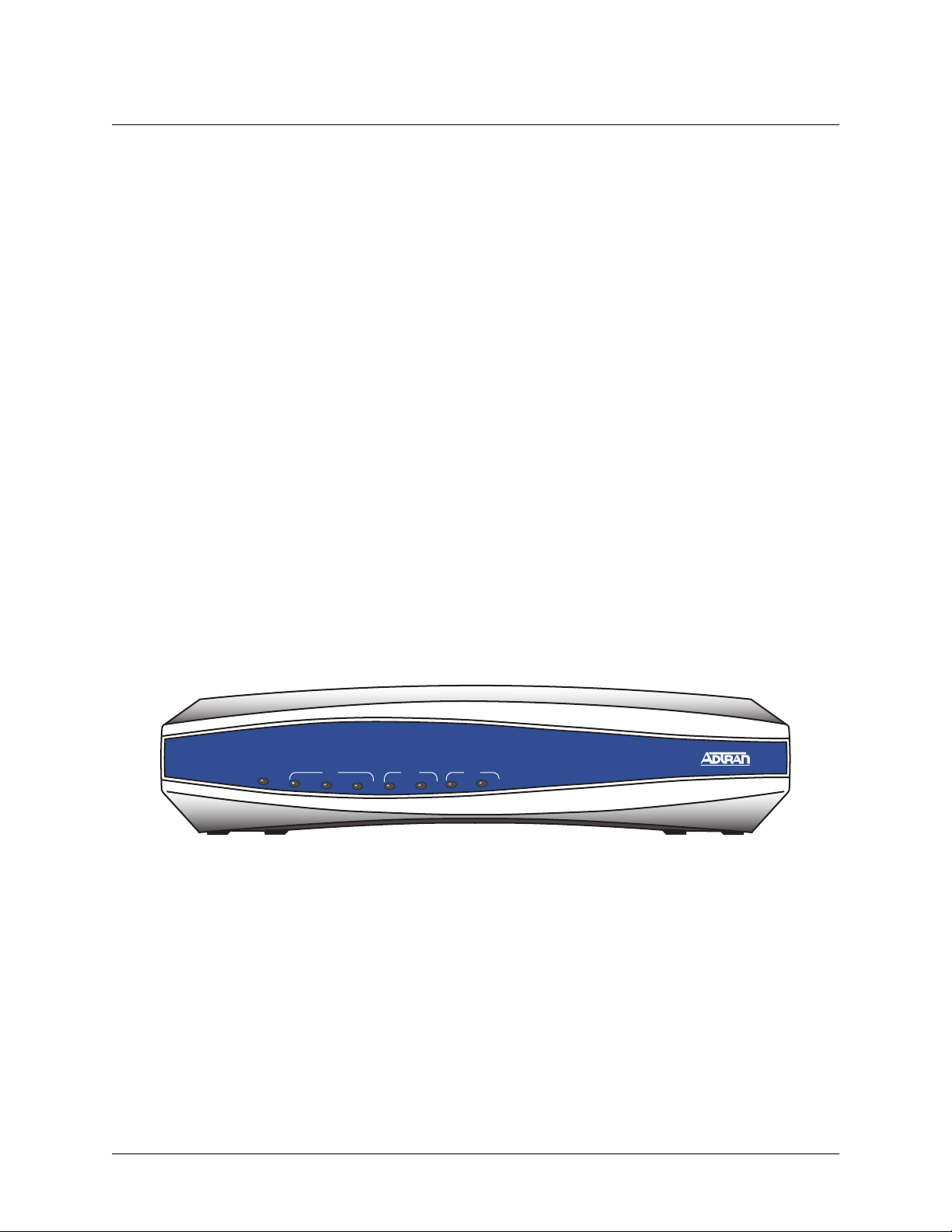
NetVanta 2050
The NetVanta 2100 front panel monitors operation by providing status LEDs for both the LAN and WAN
interfaces, as well as VPN tunnels and traffic. The front panel is shown in Figure 1.
NetVanta 2050
WAN LAN
PWR
PWR
STAT
STAT
VPN
VPN
TD
TD
RD
RD
WAN LAN
RD
TD
TD
RD
RD
TD
Figure 1. NetVanta 2050 Front Panel Layout
NetVanta 2050
16 © 2002 ADTRAN, Inc. 61200361L1-1E
Page 17
NetVanta 2000 Series System Manual Section 2, Engineering Guidelines
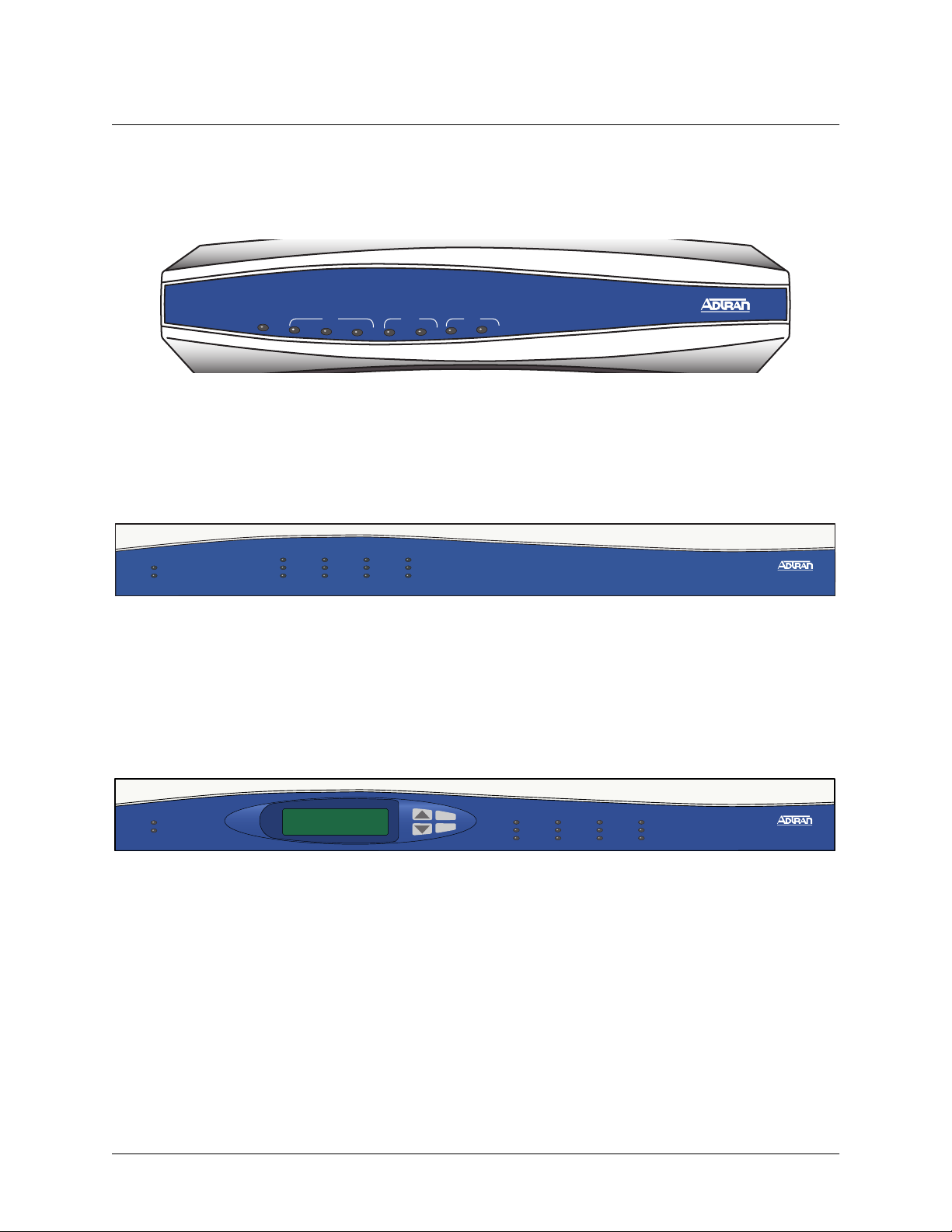
NetVanta 2100
The NetVanta 2100 front panel monitors operation by providing status LEDs for both the LAN and WAN
interfaces, as well as VPN tunnels and traffic. The front panel is shown in Figure 2.
NetVanta 2100
PWR
PWR
STAT
STAT
VPN
VPN
WAN LAN
RD
RD
WAN LAN
RD
TD
TD
TD
TD
RD
RD
TD
Figure 2. NetVanta 2100 Front Panel Layout
NetVanta 2300
The NetVanta 2300 front panel monitors operation by providing status LEDs for the LAN, WAN, and
DMZ interfaces, as well as VPN tunnels and traffic. The front panel is shown in Figure 3.
VPN
WAN
LAN
DMZ
TD
TD
RD
RD
LNK
LNK
NetVanta 2300
2300
STATUS
POWER
TD
TD
RD
RD
LNK
ACT
Figure 3. NetVanta 2300 Front Panel Layout
NetVanta 2400
The NetVanta 2300 front panel monitors operation by providing status LEDs for the LAN, WAN, and
DMZ interfaces, as well as VPN tunnels and traffic. Additionally, a LCD display provides quick-glance
access to the LAN IP parameters (IP address and subnet mask). The front panel is shown in Figure 4.
VPN
WAN
LAN
STATUS
POWER
ENTER
CANCEL
TD
TD
RD
RD
LNK
ACT
DMZ
TD
TD
RD
RD
LNK
LNK
NetVanta 2400
Figure 4. NetVanta 2400 Front Panel Layout
61200361L1-1E © 2002 ADTRAN, Inc. 17
Page 18

Section 2, Engineering Guidelines NetVanta 2000 Series System Manual
Front Panel LEDs
With the NetVanta 2000 series powered-up, the front panel LEDs provide visual information about the
status of the system. Table 1 provides a brief description of the front panel features, and Table 2 provides
detailed information about the LEDs.
Table 1. NetVanta 2000 series Front Panel Description
Feature Description
PWR Indicates whether the unit has power.
VPN (2050/2100 only) Indicates status of VPN negotiations.
VPN TD Indicates VPN traffic transmitted by the NetVanta.
VPN RD Indicates VPN traffic received by the NetVanta.
VPN ACT (2300/2400 only) Indicates status of VPN Negotiations.
LAN TD Indicates LAN traffic transmitted by the NetVanta.
LAN RD Indicates LAN traffic received by the NetVanta.
LAN LNK (2300/2400 Only) Indicates active physical link on the LAN port.
WAN TD Indicates WAN traffic transmitted by the NetVanta.
WAN RD Indicates WAN traffic received by the NetVanta.
WAN LNK (2300/2400 Only) Indicates active physical link on the WAN port.
Table 2. NetVanta 2000 series LEDs
For these LEDs... This color light... Indicates that...
PWR Red (solid) The unit has power and is in the boot process.
Green (solid) Unit has power and has successfully completed the
boot process.
VPN
(2050/2100 only)
VPN ACT
(2300/2400 Only)
Amber (slow blink) Initial Phase 1 IKE negotiation in progress.
Green (slow blink) Initial Phase 1 IKE negotiation completed successfully.
Red (slow blink) Phase 1 IKE negotiation failed.
Amber (fast blink) Phase 2 IKE negotiation in progress.
Green (solid) Phase 2 IKE negotiation completed successfully.
Red (fast blink) Phase 2 IKE negotiation failed.
Amber and Green
(alternating slow blink)
18 © 2002 ADTRAN, Inc. 61200361L1-1E
There is an active tunnel and an additional IKE Phase
1 negotiation in progress.
Page 19
NetVanta 2000 Series System Manual Section 2, Engineering Guidelines
Table 2. NetVanta 2000 series LEDs (Continued)
For these LEDs... This color light... Indicates that...
VPN TD Green (blink) Flashes with VPN data transmitted by the NetVanta
2000 series.
VPN RD Green (blink) Flashes with VPN data received by the NetVanta 2000
series.
LAN TD Green (blink) Flashes with data transmitted on the LAN interface.
LAN RD Green (blink) Flashes with data received on the LAN interface.
LAN LNK
(2300/2400 Only)
Green (solid) Unit has active physical connection on the LAN
interface.
WAN TD Green (blink) Flashes with data transmitted on the WAN interface.
WAN RD Green (blink) Flashes with data received on the WAN interface.
WAN LNK
(2300/2400 Only)
Green (solid) Unit has active physical connection on the WAN
interface.
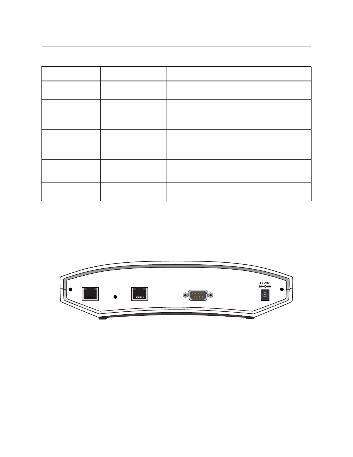
4. REVIEWING THE REAR PANEL DESIGN
NetVanta 2050 and 2100
The NetVanta 2050 and 2100 rear panel contains 2 Ethernet ports, a DB-9 serial connection, and a power
connection (see Figure 5).
WAN LAN
COM 1
POWER
Figure 5. NetVanta 2050 Rear Panel Layout
61200361L1-1E © 2002 ADTRAN, Inc. 19
Page 20
Section 2, Engineering Guidelines NetVanta 2000 Series System Manual
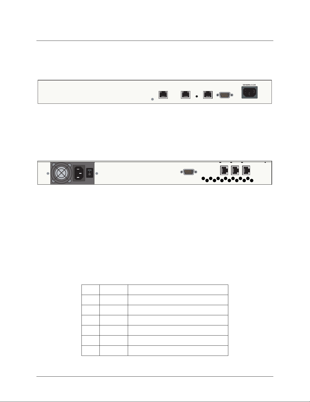
NetVanta 2300
The NetVanta 2300 rear panel contains 3 Ethernet ports, a DB-9 serial connection, and a power connection
(see Figure 6).
100-250VAC
WAN
LAN DMZ
Figure 6. NetVanta 2300 Rear Panel Layout
50/60Hz 0.2A
NetVanta 2400
The NetVanta 2300 rear panel contains 3 Ethernet ports, a DB-9 serial connection, a power connection and
ventilation openings (see Figure 7).
SERIAL
DMZLANWAN
Figure 7. NetVanta 2400 Rear Panel Layout
LAN Interface
The NetVanta 2000 series provides a standard 10/100BaseT Ethernet interface for connection to the local
corporate network. Connect the LAN interface to a hub located on your local corporate network. A DHCP
Server is enabled on the LAN interface by default. References to the LAN interface include LAN, CORP,
and Eth0
The LAN connection follows, and Ta bl e 3 shows the pinout.
Connector Type RJ-48C
Table 3. LAN Pinout
Pin Name Description
1 TX1 Transmit Positive
2 TX2 Transmit Negative
3 RX1 Receive Positive
4, 5 UNUSED —
6 RX2 Receive Negative
7, 8 UNUSED —
20 © 2002 ADTRAN, Inc. 61200361L1-1E
Page 21

NetVanta 2000 Series System Manual Section 2, Engineering Guidelines
WAN Connection
The NetVanta 2000 series provides a standard 10/100BaseT Ethernet interface for connection to the wide
area network. Connect the WAN interface to a hub connected to the router interfacing with the non-secure
Internet or the modem (cable or DSL) used for Internet access. A DHCP Client is enabled on the WAN
interface by default. References to the WAN interface include Internet, WAN, and Eth1.
Connector Type (USOC) RJ-48C
Table 4. WAN Pinout
Pin Name Description
1 TX1 Transmit Positive
2 TX2 Transmit Negative
3 RX1 Receive Positive
4, 5 UNUSED —
6 RX2 Receive Negative
7, 8 UNUSED —
DMZ Connection (NetVanta 2300 and 2400 Only)
The NetVanta 2300 and 2400 provide a standard 10/100BaseT Ethernet interface for providing public
server access. Tab le 5 shows the pinout for the DMZ port.
Connector Type (USOC) RJ-48C
Table 5. DMZ Pinout
Pin Name Description
1 TX1 Transmit Positive
2 TX2 Transmit Negative
3 RX1 Receive Positive
4, 5 UNUSED —
6 RX2 Receive Negative
7, 8 UNUSED —
61200361L1-1E © 2002 ADTRAN, Inc. 21
Page 22

Section 2, Engineering Guidelines NetVanta 2000 Series System Manual
COM1 Interface
The NetVanta 2000 series provides a DB-9 serial communication port for future command line. Ta bl e 6
shows the pinout for the DB-9 connector.
Connector Type DB-9
Table 6. DB-9 Connector Pinout
Pin Name Description
1 DCD Data Carrier Detect
2 RD Receive Data
3 TD Transmit Data
4 DTR Data Transmit Ready
5 SG Signal Ground
6 DSR Data Set Ready
7 RTS Request to Send
8 CTS Clear to Send
9 RI Ring Indicator
Power Connection
NetVanta 2050 and 2100
The NetVanta 2000 series includes a 12 VDC power supply. Connect the power supply to a standard
120VAC, 60-Hz electrical outlet for proper operation.
NetVanta 2300 and 2400
The NetVanta 2300 and 2400 include an auto sensing 100-250 VAC, 50/60 Hz power supply with a three
prong removable cable. Connect the power supply to a standard 120 VAC, 60 Hz or 220 VAC, 50 Hz
electrical outlet for proper operation.
22 © 2002 ADTRAN, Inc. 61200361L1-1E
Page 23

NetVanta 2000 Series System Manual Section 2, Engineering Guidelines
5. AT-A-GLANCE SPECIFICATIONS
Tab le 7 lists the specifications for the NetVanta 2000 series system.
Table 7. Specifications
Application Feature Specification
Firewall
Stateful Inspection Firewall Provides support against the following
attacks: IP Spoofing, Land Attack, Ping of
Death, and Reassembly Attack
Provides checks for the following attacks:
ICMP Redirect, Syn Flooding, Winnuke, and
Source Routing
IPSEC Tunnel
Encryption Encapsulating Security Payload (ESP)
DES-CBC 56-bit encryption
3DES-CBC 168-bit encryption
Authentication Authentication Header (AH)
MD5-HMAC 128-bit authentication algorithm
SHA1-HMAC 160-bit authentication algorithm
Certificate Support X.509 certificate support
IKE Manual key management for automatic key
management
61200361L1-1E © 2002 ADTRAN, Inc. 23
Page 24

Section 2, Engineering Guidelines NetVanta 2000 Series System Manual
Table 7. Specifications (Continued)
Application Feature Specification
DHCP
Server Supports three IP address ranges on local
network
User defined lease duration
Real time status of active leases
Client Ability to acquire the WAN-side IP address
from Service Provider DHCP Server
Routing
RIP Supports RIP v1, RIP v2 and a combination of
both
Separate RIP Configuration for the LAN and
WAN side
Supports RIP using Authentication Keys
Address Translation
NAT Supports one-to-one NAT (Static NAT)
NAPT Supports many-to-one (Dynamic NAT)
Reverse NAT Translates an inbound session destination IP
address
24 © 2002 ADTRAN, Inc. 61200361L1-1E
Page 25

NetVanta 2000 Series System Manual Section 2, Engineering Guidelines
Table 7. Specifications (Continued)
Application Feature Specification
Administration
Web Management Provides a GUI (graphical user interface) for
configuring the NetVanta 2000 series
SYSLOG Provides levels for logging events to an active
SYSLOG server on the network
E-Mail Alerts Capability to e-mail an alert message when
programmed thresholds are reached
Statistics User monitoring, policy, and access statistics
available
61200361L1-1E © 2002 ADTRAN, Inc. 25
Page 26

Section 2, Engineering Guidelines NetVanta 2000 Series System Manual
26 © 2002 ADTRAN, Inc. 61200361L1-1E
Page 27

NETWORK TURNUP PROCEDURE
CONTENTS
Introduction . . . . . . . . . . . . . . . . . . . . . . . . . . . . . . . . . . . . . . . . . . . . . . . . . . . . . . . . . . . . . . . . . . . . 26
Tools Required . . . . . . . . . . . . . . . . . . . . . . . . . . . . . . . . . . . . . . . . . . . . . . . . . . . . . . . . . . . . . . . . . 26
Unpack and Inspect the SYSTEM . . . . . . . . . . . . . . . . . . . . . . . . . . . . . . . . . . . . . . . . . . . . . . . . . .26
Contents of ADTRAN Shipments - NetVanta 2100. . . . . . . . . . . . . . . . . . . . . . . . . . . . . . . . . . . 26
Contents of ADTRAN Shipments - NetVanta 2300 . . . . . . . . . . . . . . . . . . . . . . . . . . . . . . . . . . 26
Supplying Power to the Unit . . . . . . . . . . . . . . . . . . . . . . . . . . . . . . . . . . . . . . . . . . . . . . . . . . . . . . 27
NetVanta 2100 . . . . . . . . . . . . . . . . . . . . . . . . . . . . . . . . . . . . . . . . . . . . . . . . . . . . . . . . . . . . . . 27
NetVanta 2300 . . . . . . . . . . . . . . . . . . . . . . . . . . . . . . . . . . . . . . . . . . . . . . . . . . . . . . . . . . . . . . 27
Installing NetVanta 2000 series Management Components . . . . . . . . . . . . . . . . . . . . . . . . . . . . . 27
Browsing Hosts Running Microsoft Windows NT, Windows 2000, or Windows 98/95 . . . . . . . . 28
Browsing Hosts Running POSIX-Compliant UNIX . . . . . . . . . . . . . . . . . . . . . . . . . . . . . . . . . . . 28
61200361L1-1E © 2002 ADTRAN, Inc. 27
Page 28

Section 3, Network Turnup Procedure NetVanta 2000 Series System Manual
1. INTRODUCTION
This section discusses the installation process of the NetVanta 2000 series systems.
2. TOOLS REQUIRED
The tools required for installation of the NetVanta 2000 series systems are:
• CATV-UTP Ethernet cable to connect the unit to the existing network
• An Internet browser for configuring the unit
To prevent electrical shock, do not install equipment in a wet location or during a
lightning storm.
3. UNPACK AND INSPECT THE SYSTEM
Each NetVanta 2000 series unit is shipped in its own cardboard shipping carton. Open each carton
carefully and avoid deep penetration into the carton with sharp objects.
After unpacking the unit, inspect it for possible shipping damage. If the equipment has been damaged in
transit, immediately file a claim with the carrier, then contact ADTRAN Customer Service (see Customer
Service, Product Support Information, and Training in the front of this manual).
Contents of ADTRAN Shipments - NetVanta 2050 and 2100
Your ADTRAN shipment includes the following items:
• The NetVanta 2050 or 2100 Unit
• The NetVanta 2000 series User Manual CD (ADTRAN P/N 3253041)
• AC Power supply - (ADTRAN P/N 336012 VUR01)
• Crossover Ethernet cable for connecting the NetVanta 2100 directly to a PC
(ADTRAN P/N 8125M012)
Contents of ADTRAN Shipments - NetVanta 2300 and 2400
Your ADTRAN shipment includes the following items:
• The NetVanta 2300 or 2400 Unit
• The NetVanta 2000 series User Manual CD (ADTRAN P/N 3253041)
• AC Power cable (ADTRAN P/N 3127009)
• (2) Brackets for installing the unit in a rackmount configuration (ADTRAN P/N 3265479)
28 © 2002 ADTRAN, Inc. 61200361L1-1E
Page 29

NetVanta 2000 Series System Manual Section 3, Network Turnup Procedure
4. SUPPLYING POWER TO THE UNIT
NetVanta 2050 and 2100
The AC powered NetVanta 2050 and 2100 come equipped with a detachable 12 VDC at 800 mA
wallmount power supply for connecting to a grounded power receptacle. As shipped, the NetVanta 2050
and 2100 are set to factory default conditions. After installing the unit, the NetVanta 2050 and 2100 are
ready for power-up. To power-up the unit, connect the unit to an appropriate power source.
• This unit shall be installed in accordance with Article 400 and 364.8 of the NEC NFPA
70 when installed outside of a Restricted Access Location (i.e., central office, behind a
locked door, service personnel only area).
• Power to the NetVanta 2050/2100 AC system must be from a grounded 90-130 VAC,
50/60 Hz source.
• The power receptacle uses double-pole, neutral fusing.
• Maximum recommended ambient operating temperature is 45
o
C.
NetVanta 2300 and 2400
The AC powered NetVanta 2300 adn 2400 come equipped with an auto-sensing 100-240 VAC, 50-60 Hz
power supply for connecting to a grounded power receptacle. A grounded three plug detachable cable is
included with the shipment. As shipped, the NetVanta 2300 and 2400 are set to factory default conditions.
After installing the unit, the NetVanta 2300 and 2400 are ready for power-up. To power-up the unit,
connect the unit to an appropriate power source.
• This unit shall be installed in accordance with Article 400 and 364.8 of the NEC NFPA
70 when installed outside of a Restricted Access Location (i.e., central office, behind a
locked door, service personnel only area).
• Power to the NetVanta 2300/2400 AC system must be from a grounded 100-240 VAC,
50/60 Hz source.
• The power receptacle uses double-pole, neutral fusing.
• Maximum recommended ambient operating temperature is 45
o
C.
5. INSTALLING NETVANTA 2000 SERIES MANAGEMENT COMPONENTS
Configuring the NetVanta 2000 series unit through the web interface requires a host computer with an
Ethernet interface and a web browser. ADTRAN recommends using Internet Explorer 5.0 or greater for
optimal viewing of configuration web pages.
The NetVanta 2000 series of products contains a default IP address of 10.10.10.1 and a netmask of
255.255.255.0. Select an IP address in the same range as the NetVanta unit and assign it to the host
computer running the web browser. An example IP address is 10.10.10.10 with a subnet mask of
255.255.255.0. This section contains detailed procedures for assigning the selected IP address to a host
computer for each of the popular operating systems.
61200361L1-1E © 2002 ADTRAN, Inc. 29
Page 30
Section 3, Network Turnup Procedure NetVanta 2000 Series System Manual
If you have a PC with DHCP client capabilities enabled, connect the NetVanta 2000 series
unit directly to your computer using the supplied ethernet crossover cable and follow the
procedure in DLP-1, Connecting to the Netvanta 2000 Series to connect for the first time.
The NetVanta 2000 series products have a DHCP Server capabilities enabled by
default. Connecting the unit to a network with a functioning DHCP server can cause
IP address assignment conflicts.
For any operating system not discussed in this section, refer to the system’s user
documentation for instructions on assigning IP addresses.
Browsing Hosts Running Microsoft Windows NT, Windows 2000, or Windows 98/95
1. Follow the menu path S
TART>SETTINGS>CONTROL PANEL
.
2. After the
C
ONTROL PANEL
appears, double-click the N
ETWORK
icon to display the existing network
configuration.
3. Select
TCP/IP from the list of installed network components. If there are multiple sessions, select
the one for the Ethernet card in the host computer.
4. Click
P
ROPERTIES
, which shows the existing properties of the TCP/IP protocol running on the host
computer in a multi-paned window.
5. Select the
6. Check the
7. Enter the
8. Click
9. Click
OK to close the properties window.
OK on the network configuration window, which will ask you to reboot the browser
IP A
DDRESS
S
PECIFY AN
IP A
DDRESS
pane by clicking on it.
IP A
DDRESS
radio button.
as: 10.10.10.50 and S
UBNET MASK
as: 255.255.255.0.
computer.
Y
to reboot your computer.
10. Click
ES
Browsing Hosts Running POSIX-Compliant UNIX
1. Log in as root, or change to superuser.
2. Run the ifconfig command -a option to list the configured network interfaces in the system. This
will show the Ethernet interface name as well. For example:
#ifconfig -a
lo0: flags=863<UP,LOOPBACK,RUNNING,MULTICAST> mtu 8232 inet 127.0.0.1 netmask
ff000000
hme0: flags=863<UP,BROADCAST,NOTRAILERS,RUNNING,MULTICAST> mtu 1500
inet 192.103.55.186 netmask ffffff00 broadcast 192.103.255.255
30 © 2002 ADTRAN, Inc. 61200361L1-1E
Page 31

NetVanta 2000 Series System Manual Section 3, Network Turnup Procedure
ether 8:0:20:a8:38:c6
3. Change the IP address of the Ethernet interface to 10.10.10.50 with subnet mask 255.255.255.0 by
using the ifconfig command. For example:
# ifconfig eth0 10.10.10.50 netmask 255.255.255.0
4. Run the ifconfig command -a option again to make sure the interface address change is effective.
61200361L1-1E © 2002 ADTRAN, Inc. 31
Page 32

Section 3, Network Turnup Procedure NetVanta 2000 Series System Manual
32 © 2002 ADTRAN, Inc. 61200361L1-1E
Page 33

USER INTERFACE GUIDE
CONTENTS
Navigating the Administration Console . . . . . . . . . . . . . . . . . . . . . . . . . . . . . . . . . . . . . . . . . . . . . 34
Administration Console . . . . . . . . . . . . . . . . . . . . . . . . . . . . . . . . . . . . . . . . . . . . . . . . . . . . . . . . 34
Menu Overview . . . . . . . . . . . . . . . . . . . . . . . . . . . . . . . . . . . . . . . . . . . . . . . . . . . . . . . . . . . . . . . . . 35
Config . . . . . . . . . . . . . . . . . . . . . . . . . . . . . . . . . . . . . . . . . . . . . . . . . . . . . . . . . . . . . . . . . . . . . 35
Admin . . . . . . . . . . . . . . . . . . . . . . . . . . . . . . . . . . . . . . . . . . . . . . . . . . . . . . . . . . . . . . . . . . . . . 36
Policies . . . . . . . . . . . . . . . . . . . . . . . . . . . . . . . . . . . . . . . . . . . . . . . . . . . . . . . . . . . . . . . . . . . . 37
Monitor . . . . . . . . . . . . . . . . . . . . . . . . . . . . . . . . . . . . . . . . . . . . . . . . . . . . . . . . . . . . . . . . . . . . 38
Menu Descriptions . . . . . . . . . . . . . . . . . . . . . . . . . . . . . . . . . . . . . . . . . . . . . . . . . . . . . . . . . . . . . . 39
> Config. . . . . . . . . . . . . . . . . . . . . . . . . . . . . . . . . . . . . . . . . . . . . . . . . . . . . . . . . . . . . . . . . . . . 39
> Admin. . . . . . . . . . . . . . . . . . . . . . . . . . . . . . . . . . . . . . . . . . . . . . . . . . . . . . . . . . . . . . . . . . . . 47
> Logout . . . . . . . . . . . . . . . . . . . . . . . . . . . . . . . . . . . . . . . . . . . . . . . . . . . . . . . . . . . . . . . . . . . 49
> Policies. . . . . . . . . . . . . . . . . . . . . . . . . . . . . . . . . . . . . . . . . . . . . . . . . . . . . . . . . . . . . . . . . . . 50
Changing the Priority of a Policy . . . . . . . . . . . . . . . . . . . . . . . . . . . . . . . . . . . . . . . . . . . . . . . . . 59
Default Access Policies . . . . . . . . . . . . . . . . . . . . . . . . . . . . . . . . . . . . . . . . . . . . . . . . . . . . . . . . 59
Changing the Priority of a Policy . . . . . . . . . . . . . . . . . . . . . . . . . . . . . . . . . . . . . . . . . . . . . . . . . 64
Default Access Policies . . . . . . . . . . . . . . . . . . . . . . . . . . . . . . . . . . . . . . . . . . . . . . . . . . . . . . . . 64
Deleting A VPN Policy. . . . . . . . . . . . . . . . . . . . . . . . . . . . . . . . . . . . . . . . . . . . . . . . . . . . . . . . . 64
Editing A VPN Policy. . . . . . . . . . . . . . . . . . . . . . . . . . . . . . . . . . . . . . . . . . . . . . . . . . . . . . . . . . 65
Viewing A VPN Policy . . . . . . . . . . . . . . . . . . . . . . . . . . . . . . . . . . . . . . . . . . . . . . . . . . . . . . . . . 65
Changing Priority of A VPN Policy . . . . . . . . . . . . . . . . . . . . . . . . . . . . . . . . . . . . . . . . . . . . . . . 65
ESP Configuration. . . . . . . . . . . . . . . . . . . . . . . . . . . . . . . . . . . . . . . . . . . . . . . . . . . . . . . . . . . . 67
AH Configuration. . . . . . . . . . . . . . . . . . . . . . . . . . . . . . . . . . . . . . . . . . . . . . . . . . . . . . . . . . . . . 69
ESP Configuration. . . . . . . . . . . . . . . . . . . . . . . . . . . . . . . . . . . . . . . . . . . . . . . . . . . . . . . . . . . . 69
> Monitor . . . . . . . . . . . . . . . . . . . . . . . . . . . . . . . . . . . . . . . . . . . . . . . . . . . . . . . . . . . . . . . . . . . 72
FIGURES
Figure 1. NetVanta 2000 series Administration Console. . . . . . . . . . . . . . . . . . . . . . . . . . . . . . . . 34
Figure 2. C
Figure 3. A
Figure 4. P
Figure 5. M
61200361L1-1E © 2002 ADTRAN, Inc. 33
ONFIG
Menu Information . . . . . . . . . . . . . . . . . . . . . . . . . . . . . . . . . . . . . . . . . . . . . . . 35
DMIN
Menu Information . . . . . . . . . . . . . . . . . . . . . . . . . . . . . . . . . . . . . . . . . . . . . . . . 36
OLICIES
ONITOR
Menu Information . . . . . . . . . . . . . . . . . . . . . . . . . . . . . . . . . . . . . . . . . . . . . . 37
Menu Information . . . . . . . . . . . . . . . . . . . . . . . . . . . . . . . . . . . . . . . . . . . . . . 38
Page 34

Section 4, User Interface Guide NetVanta 2000 Series System Manual
1. NAVIGATING THE ADMINISTRATION CONSOLE
The NetVanta 2000 series uses a web-based Administration Console for displaying both menu options and
data fields. All menu options display in the Administration Console Header (see Figure 1), through which
you have complete control of the NetVanta 2000 series.
Figure 1. NetVanta 2000 series Administration Console
Administration Console
The A
DMINISTRATION CONSOLE
the appropriate menu selections. This header remains visible as you navigate through the individual menu
pages. The console contains a main menu bar and a menu list.
shows the available areas of configuration for the NetVanta 2000 series and
Menu Bar
The A
DMINISTRATION CONSOLE
series. They are
C
ONFIG
, A
the hyperlink displays the applicable menu options in the menu list (located on the left side of the screen).
menu bar displays the four areas of configuration for the NetVanta 2000
DMIN
, P
OLICIES
, and M
ONITOR
. Selecting an area of configuration by clicking on
Menu List
The A
DMINISTRATION CONSOLE
desired menu from the menu bar). Each menu list selection is a hyperlink which displays the applicable
menu items and data fields in the display window.
34 © 2002 ADTRAN, Inc. 61200361L1-1E
menu list displays the selections available from the active menu (enable the
Page 35
NetVanta 2000 Series System Manual Section 4, User Interface Guide
2. MENU OVERVIEW
The NetVanta 2000 series configuration is divided into four main areas: C
M
ONITOR
. This section gives a brief discussion of each area and the menu options available. Menu
Descriptions on page 39 and following gives a more detailed discussion of these menu options.
ONFIG
, A
DMIN
, P
OLICIES
, and
CONFIG
The C
IP addresses assigned to the network interfaces, setting up a routing table, Firewall settings, and DHCP
server configuration. Figure 2 shows the available menu options (displayed in the option list) for the
C
ONFIG
menu contains the basic configuration parameters of the NetVanta 2000 series box including
ONFIG
menu.
Figure 2. C
61200361L1-1E © 2002 ADTRAN, Inc. 35
Menu Information
ONFIG
Page 36

Section 4, User Interface Guide NetVanta 2000 Series System Manual
ADMIN
The A
such as changing the root password, saving the configuration to permanent storage, factory defaults, and
rebooting the system. Figure 3 shows the available menu options (displayed in the option list) for the
A
DMIN
menu contains the various system administration activities on the NetVanta 2000 series box
DMIN
menu.
Figure 3. A
36 © 2002 ADTRAN, Inc. 61200361L1-1E
Menu Information
DMIN
Page 37

NetVanta 2000 Series System Manual Section 4, User Interface Guide
POLICIES
The P
OLICIES
Through the available menu options you can define the policies and determine how to maintain different
policy component tables (see Figure 4).
menu contains the system wide access policies and user-group specific access policies.
Figure 4. P
61200361L1-1E © 2002 ADTRAN, Inc. 37
OLICIES
Menu Information
Page 38

Section 4, User Interface Guide NetVanta 2000 Series System Manual
MONITOR
The M
ONITOR
Through the available menu options you can view the status of remote user sessions, configure the log
message categories, and view the log messages stored in the NetVanta 2000 series event log queue. Figure
5 shows the available menu options (displayed in the option list) for the
menu contains all information pertinent to policy statistics, user accounting, and log usage.
M
ONITOR
menu.
Figure 5. M
38 © 2002 ADTRAN, Inc. 61200361L1-1E
ONITOR
Menu Information
Page 39

NetVanta 2000 Series System Manual Section 4, User Interface Guide
3. MENU DESCRIPTIONS
The NetVanta 2000 series comes pre-configured with a default IP address of 10.10.10.1 assigned to the
corporate interface (LAN). To begin the configuration of the NetVanta 2000 series, point the active
browser on your computer to http://10.10.10.1
. Once the browser has successfully connected to the unit
you will be presented with the login screen. You must log in using a valid user name and password to start
the NetVanta 2000 series configuration in a MD5 authenticated web session. When setting up the first
MD5 authenticated session, the default user name is
admin
. There is no password set for this user. Refer to
DLP-001, Connecting to the Netvanta 2000 Series, for more instructions on logging in to the unit.
Enter
admin
in the user name field and click on the L
OGIN NOW
button. The NetVanta 2000 series Welcome
page will display after the login process has been successfully completed. You can now proceed with the
NetVanta 2000 series configuration.
ADTRAN strongly recommends immediately changing the admin password. Refer to
DLP-002, Changing the Admin Password in the NetVanta.
> CONFIG
This section discusses the basic configuration of the NetVanta 2000 series including IP addresses assigned
to the network interfaces, setting up a routing table, Firewall settings, and DHCP server configuration.
The basic configuration of the NetVanta 2000 series can be displayed by clicking on the
C
ONFIG
menu on
the Administration Console. Basic configuration includes setting the date and time on the box, network
interface configuration, setting up the IP routing table, basic firewall configuration, event logging
configuration, web proxy configuration, and DHCP (Dynamic Host Configuration Protocol) server
configuration.
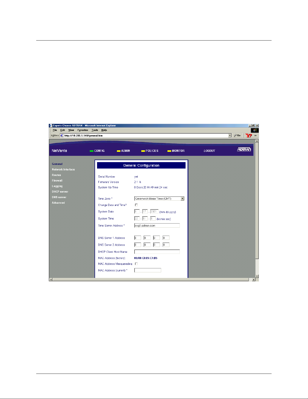
> CONFIG > GENERAL
The General Configuration page is displayed by clicking on G
ENERAL
side of the display window.
This page displays the important information of your NetVanta 2000 series system including the
N
UMBER
, current F
IRMWARE VERSION
, and S
YSTEM UP TIME
. Please have this information available before
contacting the ADTRAN Technical Support team at (888) 4-ADTRAN (423-8726).
To set the system date and time, enter the current date in the form mm-dd-yyyy (example: March 3, 2001 is
03-03-2001) and time in the form hours:minutes:seconds (example 11:02 pm is 23:02:00). Select the
C
HANGE DATE AND TIME
? checkbox and click the S
button to enter the new date and time.
UBMIT
The DNS server configuration for the NetVanta 2000 series is also located on the General Configuration
page. If the NetVanta 2000 series needs to resolve domain names it will use the DNS server IP address
configured here. Configuring a DNS server IP address is optional.
found in the menu list on the left
S
ERIAL
61200361L1-1E © 2002 ADTRAN, Inc. 39
Page 40

Section 4, User Interface Guide NetVanta 2000 Series System Manual
> CONFIG > NETWORK INTERFACE
The Network Interface configuration page is displayed by clicking on N
option list on the left side of the display window.
ETWORK INTERFACE
found in the
> CONFIG > NETWORK INTERFACE > ETHERNET CONFIG > ETHERNET IP ADDRESS
The E
THERNET
addresses, and subnet masks.
The
C
ORPORATE
corporate network connected to the LAN interface located on the back of the NetVanta 2000 series unit.
The
WAN IP T
or
STATIC if your ISP has assigned you a specific IP address to use each time you connect. If your WAN IP
is S
YPE
T
provided by your ISP.
The NetVanta 2000 series also supports PPPoE (PPP over Ethernet) to obtain a WAN interface IP address.
Select the
appropriate fields.
IP A
DDRESS
IP and S
should be set to D
YPE
, the WAN IP and S
TATIC
PPPOE radio button and enter the U
section contains the information for both the Corporate (LAN) and WAN IP
UBNET MASK
fields should be configured with parameters that correspond to the
YNAMIC
UBNET MASKS
if your ISP is using DHCP to assign IP addresses dynamically
fields should be configured with the specific information
SERNAME
and P
ASSWORD
provided by your ISP in the
> CONFIG > NETWORK INTERFACE > RIP CONFIG > RIP CONFIGURATION
The R
IP CONFIGURATION
standard Rip V1. The NetVanta 2000 series supports RIP V1 on both the LAN and WAN interfaces.
RIPTWO is standard RIP V2. NetVanta 2000 series supports RIP V2 on both the LAN and WAN
interfaces.
RIPCOMP is a combination of RIP V1 and RIP V2. When configured for RIPCOMP, the
NetVanta 2000 series is capable of listening to RIP V1 updates while maintaining full compatibility with
RIP V2 systems.
field selects the RIP version being used by the NetVanta 2000 series. RIPONE is
> CONFIG > NETWORK INTERFACE > RIP CONFIG > AUTHENTICATION TYPE
The Authentication Type field configures the NetVanta 2000 series to use the selected authentication when
performing RIP functions. If authentication is configured, other systems providing the NetVanta 2000
series with RIP updates must be configured for matching authentication. The NetVanta 2000 series
supports both
entered in the
SIMPLEAUTH (using a single password) or MD5 authentication (requiring the use of keys
MD5 AUTH KEY ID and MD5 AUTH KEY fields.
> CONFIG > NETWORK INTERFACE > DHCP INFO
The DHCP I
for both the LAN and WAN ports. This table is only valid if the NetVanta 2000 series is connected to a
network with an active DHCP server.
table for the NetVanta 2000 series displays the current DHCP client interface information
NFO
> CONFIG > ROUTES
The Routing table for the NetVanta 2000 series can be reached by clicking on R
list on the left side of the display window. The following is a description of the routing table fields.
found in the menu
OUTES
40 © 2002 ADTRAN, Inc. 61200361L1-1E
Page 41

NetVanta 2000 Series System Manual Section 4, User Interface Guide
> CONFIG > ROUTES > DESTINATION IP
The D
ESTINATION
NetVanta 2000 series uses this information when making routing decisions.
IP address field displays the IP address of the destination network for the route. The
> CONFIG > ROUTES > INTERFACE NAME
The I
NTERFACE NAME
route. The options are:
located on the back panel of the unit).
field displays the name of the interface that is accessed to send data using the listed
0 (the LAN port located on the back panel of the unit) and
ETH
1 (the WAN port
ETH
> CONFIG > ROUTES > NETMASK
The N
ET MASK
identify subnetworks to allow for IP sharing on a LAN.
field displays the current subnet mask used for the listed route. Subnet masks are used to
> CONFIG > ROUTES > GATEWAY IP
The G
ATEWAY
for its assigned network. The IP route table for the gateway of a network should contain routes to all
available subnets on the network.
IP field displays the IP address of the first intelligent device that intercepts and steers data
> CONFIG > ROUTES > HOP COUNT
The H
OP COUNT
their destination.
field displays the number of gateways datagrams pass through when taking this route to
> CONFIG > ROUTES > TYPE
The T
L
OCAL
field designates whether a route was configured or learned. Configured routes show up as
YPE
. Learned routes show up as D
YNAMIC
.
> CONFIG > ROUTES > DELETE ROUTE
Select the routing entry you want to delete by choosing the corresponding checkbox and clicking the
D
ELETE ROUTE
button. This will delete the selected route entry.
Before clicking the D
ELETE ROUTE
button, make sure that you have selected the correct
routing entry. Removing the routing entry for a destination may make it inaccessible.
> CONFIG > FIREWALL
The F
IREWALL CONFIGURATION
left side of the display window. This page provides control to activate different cyber attack checks. The
event logging thresholds for cyber attacks are also configured on the
page can be accessed by clicking on F
IREWALL
F
found in the menu list on the
IREWALL CONFIGURATION
page.
61200361L1-1E © 2002 ADTRAN, Inc. 41
Page 42

Section 4, User Interface Guide NetVanta 2000 Series System Manual
> CONFIG > FIREWALL > IP SPOOFING CHECK
IP Spoofing is a network intrusion that occurs when an outside user gains access to a computer on the
network by pretending to be at a trusted IP address.
IP S
POOFING CHECK
is always E
NABLED
, and the
NetVanta 2000 series discards any packets received on the WAN interface containing a source IP address
on the corporate network.
> CONFIG > FIREWALL > PING OF DEATH CHECK
Ping of Death is a denial of service attack which exploits the errors in the oversize datagram handling
mechanism of a TCP/IP stack. Many popular operating systems have difficulty handling datagrams larger
than then maximum datagram size defined by the IP standard. If hosts running these operating systems
encounter oversized ping packets, it is likely they will hang or crash causing network problems.
D
EATH CHECK
is always E
NABLED
, and the NetVanta 2000 series becomes the central entry point for all
P
ING OF
traffic entering the corporate network and it watches for such non-standard IP datagrams to filter them
before they reach vulnerable hosts on the network.
> CONFIG > FIREWALL > LAND ATTACKS CHECK
Land Attacks are a special type of denial of service attack on TCP-based services such as HTTP, SMTP,
and FTP. In a Land Attack an attacker forges the equal values for the source and destination port, and
source and destination IP addresses. These port values are often the well-known service port values, and
the IP addresses are the target hosts’s IP address. This attack exploits the inappropriate implementation of
the TCP connections establishment protocol in a TCP/IP stack; as a result the target server enters an
uncontrollable infinite spin and eventually the system crashes.
and the NetVanta 2000 series ensures that all service requests made to any of the hosts in the corporate
network are Land Attack free.
L
AND ATTACK CHECK
is always E
NABLED
,
> CONFIG > FIREWALL > REASSEMBLY ATTACK
Datagrams traveling in the Internet may pass through heterogeneous networks which require them to be
fragmented and reassembled at their destinations. Certain popular TCP/IP implementations cannot handle
all datagram reassembly scenarios properly. If an attacker sends datagram fragments to a host with limited
datagram reassembly capabilities the host is likely to behave unpredictably.
E
NABLED
, and the NetVanta 2000 series invokes its robust datagram reassembly engine to perform the
R
EASSEMBLY ATTACK
is always
datagram reassembly strictly conforming to IP standards.
> CONFIG > FIREWALL > SYN FLOODING ATTACK CHECK
SYN Flooding is a well-known denial of service attack on TCP based services. TCP requires a 3-way
handshake before the actual communications between two hosts begins. A server must allocate resources
to process new connection requests that are received. A malicious intruder is capable of transmitting large
amounts of service requests in a very short period causing servers to allocate all resources to process the
incoming requests. If
service requests and allows only legitimate requests to pass through.
SYN F
LOODING ATTACK CHECK
is selected, the NetVanta 2000 series filters out phony
42 © 2002 ADTRAN, Inc. 61200361L1-1E
Page 43

NetVanta 2000 Series System Manual Section 4, User Interface Guide
> CONFIG > FIREWALL > ICMP REDIRECT CHECK
ICMP Redirect is a standard ICMP message used to provide hosts with better route information to the
source. When this message is received, the recipient updates its routing table with the new routing
information provided with no authentication required. An intruder can provide a target with the route
information of his or her interest thereby gaining access to the hosts routing table. It is possible for an
intruder to access the data originated from the target hosts once the hosts routing table has been
compromised. If
ICMP R
EDIRECT CHECK
is E
NABLED
, the NetVanta 2000 series discards all ICMP Redirect
messages.
> CONFIG > FIREWALL > SOURCE ROUTING CHECK
Strict and loose source routing (as specified in IP standard RFC 791) allows datagrams to take a predefined
path towards a destination. An intruder can gain detailed information about the corporate network by
tracking datagrams through the corporate network. If
S
OURCE ROUTING CHECK
is E
NABLED
, the NetVanta
2000 series filters out all datagrams that contain the strict or loose source routing option.
> CONFIG > FIREWALL > WINNUKE ATTACK CHECK
WinNuke attack is a well-known denial of service attack on hosts running Windows operating systems. A
malicious intruder sends Out of Band (OOB) data over an established connection to a Windows user.
Windows cannot properly handle the OOB data and the host reacts unpredictably. Normal shut-down of the
hosts will generally return all functionality. If
series filters OOB data to prevent network problems.
WINN
UKE ATTACK CHECK
is selected, the NetVanta 2000
> CONFIG > FIREWALL > EVENT LOGGING THRESHOLDS
Event logging thresholds prevent large quantities of duplicate logs if the NetVanta 2000 series or the
corporate network connected to it is under attack.
The
LOG A
TTACKS FOR EVERY
threshold indicates the number of attack mounting attempts the NetVanta
2000 series should see before generating a log message. The default value for an attack log threshold is
100.
The
LOG P
OLICY FOR EVERY
threshold defines the number of connections required by an access policy
through the NetVanta 2000 series before a log message is generated for that policy. The default value for
the policy access log threshold is 100.
The
LOG VPN
FOR EVERY
threshold defines the number of VPN enabled connections required by a VPN
policy before generating a log message for that policy. The default value for the VPN log threshold is 100.
> CONFIG > LOGGING
The NetVanta 2000 series periodically exports event log messages to well-secured external systems for
secondary storage. The NetVanta 2000 series provides two industry-standard ways to export the event log:
e-mail and syslog. Log messages may be e-mailed to specified addresses, exported to a standard syslog
service, or a combination of both. The Logging Configuration page is displayed by clicking on Logging in
the menu list on the left side of the display window.
61200361L1-1E © 2002 ADTRAN, Inc. 43
Page 44

Section 4, User Interface Guide NetVanta 2000 Series System Manual
> CONFIG > LOGGING > LOG EXPORT SYSTEM
The Syslog Configuration page is displayed by clicking on the L
OG EXPORT SYSTEM
Logging submenu in the menu list. The configuration parameters for exporting event log messages using
the syslog service are displayed on this page.
hyperlink listed as a
> CONFIG > LOGGING > LOG EXPORT SYSTEM > LOG QUEUE LENGTH
The L
OG QUEUE LENGTH
triggering the log export process.
field defines the number of events to be collected in the log queue before
> CONFIG > LOGGING > LOG EXPORT SYSTEM > LOGTIME THRESHOLD
The L
OGTIME THRESHOLD
the log export process.
defines the maximum time interval (in minutes) which passes before triggering
> CONFIG > LOGGING > LOG EXPORT SYSTEM > DEVICE NAME
The D
EVICE NAME
identify the event log messages generated by the NetVanta 2000 series in a common log file. Using a
descriptive firewall name is useful when searching through the large log files.
field is an alphanumeric string attached to each log and alert message. This helps
> CONFIG > LOGGING > LOG EXPORT SYSTEM > ENABLE SYSLOG NOTIFICATION
The E
NABLE SYSLOG NOTIFICATION
syslog service.
check box configures the NetVanta 2000 series to export the log to the
> CONFIG > LOGGING > LOG EXPORT SYSTEM > SYSLOG SERVER
The S
YSLOG SERVER
on the corporate network.
field defines the syslog server’s IP address. The syslog server should be maintained
> CONFIG > LOGGING > LOG EXPORT SYSTEM > SYSLOG FACILITY
The S
YSLOG FACILITY
exporting log entries to the syslog service. Nine priority levels are provided ranging from SYSLOG_LOCAL0
to SYSLOG_LOCAL8. Choose any one of these priority levels and configure the syslog service accordingly.
For configuring the syslog service on the server, refer to the syslog documentation.
drop-down menu selects the syslog priority level which the NetVanta 2000 series uses for
> CONFIG > LOGGING > LOG EXPORT SYSTEM > ENABLE E-MAIL NOTIFICATION
The E
e-mail.
NABLE
E-M
AIL NOTIFICATION
check box configures the NetVanta 2000 series to export event logs through
> CONFIG > LOGGING > LOG EXPORT SYSTEM > MAIL SERVER ADDRESS
The M
AIL SERVER ADDRESS
series to e-mail out the log.
field defines the IP address of the SMTP server used by the NetVanta 2000
44 © 2002 ADTRAN, Inc. 61200361L1-1E
Page 45

NetVanta 2000 Series System Manual Section 4, User Interface Guide
> CONFIG > LOGGING > LOG EXPORT SYSTEM > RETURN MAIL ADDRESS
The R
ETURN MAIL ADDRESS
containing the NetVanta 2000 series event log messages.
field is an alphanumeric string that appears in the ‘From:’ field in all e-mail
> CONFIG > LOGGING > LOG EXPORT SYSTEM > EMAIL GENERAL LOG TO:
The EM
AIL GENERAL LOG TO
messages via e-mail.
: address is used by the NetVanta 2000 series when exporting event log
> CONFIG > LOGGING > LOG EXPORT SYSTEM > EMAIL ALERT LOG TO:
The EM
address.
AIL ALERT LOG TO
: address allows the NetVanta 2000 series to send alert logs only to the specified
> CONFIG > DHCP SERVER
The NetVanta 2000 series is equipped with Dynamic Host Configuration Protocol (DHCP) server
capabilities. A DHCP server eliminates static network configuration for hosts connected to the corporate
network by configuring them dynamically. A DHCP server manages the IP address pool in the corporate
network by leasing IP addresses to requesting hosts. It also supplies DNS configuration and default route
information to the requesting hosts. All requesting hosts must be running DHCP enabled operating
systems.
> CONFIG > DHCP SERVER > DHCP CONFIG
The DHCP C
submenu in the menu list. A description of the DHCP Server Configuration parameters follows.
page is displayed by clicking on the DHCP C
ONFIG
hyperlink listed as a DHCP server
ONFIG
> CONFIG > DHCP SERVER > DHCP CONFIG > DHCP ENABLED
The DHCP E
2000 series.
NABLED
radio button allows you to enable or disable the DHCP server capabilities of NetVanta
> CONFIG > DHCP SERVER > DHCP CONFIG > IP ADDRESS RANGE
IP A
DDRESS RANGE
DHCP enabled hosts. The IP address ranges must be included in the corporate network.
(1-3) fields specify up to three disjoint IP address ranges for leasing IP addresses to
> CONFIG > DHCP SERVER > DHCP CONFIG > GATEWAY IP ADDRESS
The G
ATEWAY
configuration requires this to be populated with the IP address assigned to the LAN port of NetVanta 2000
series.
IP A
DDRESS
field specifies the default gateway supplied to DHCP enabled hosts. Normal
> CONFIG > DHCP SERVER > DHCP CONFIG > DNS1/DNS2
The DNS 1-2 fields define the primary and secondary DNS server IP addresses supplied to the DHCP
enabled hosts in the corporate network.
61200361L1-1E © 2002 ADTRAN, Inc. 45
Page 46

Section 4, User Interface Guide NetVanta 2000 Series System Manual
> CONFIG > DHCP SERVER > DHCP CONFIG > LEASE DURATION
The L
EASE DURATION
assigned IP address. At the end of the lease duration, the host must send the DHCP server a lease renewal
request for the assigned IP address. If the request is denied the host must relinquish the address and send a
request for a new IP address to be assigned.
field defines the amount of time (in seconds) that a DHCP enabled host may lease an
> CONFIG > DHCP SERVER > ACTIVE LEASES
The A
CTIVE LEASES
DHCP server) to devices located on the LAN network.
page displays the DHCP leases that have been assigned (by the NetVanta 2000 series
> CONFIG > DNS SERVER
The NetVanta 2000 series comes equipped with a DNS server. To enter DNS names to the DNS Server
lookup table, enter the
IP A
DDRESS
field.
DNS N
in the appropriate field and the corresponding IP address beside it in the
AME
> CONFIG > ADVANCED
The A
DVANCED CONFIGURATION
side of the display window. The NetVanta 2000 series advanced configuration includes, box access
configuration and service timeout parameters.
page is displayed by clicking A
DVANCED
in the menu list located on the left
> CONFIG > ADVANCED > BOX ACCESS
The Box Access C
ONFIGURATION
Advanced Configuration submenu in the menu list. This page defines the access scheme for the NetVanta 2000
series system including both corporate network (LAN) and Internet (WAN) access.
page is displayed by clicking on the B
OX ACCESS
hyperlink listed as an
> CONFIG > ADVANCED > BOX ACCESS > LAN
The A
LWAYS ALLOW ADMIN LOGIN
status for the NetVanta 2000 series corporate network (LAN) interface. NetVanta 2000 series remote
administration is always allowed from the host having the specific IP address configured in this field.
Only use a trusted host IP address in the
The
A
LLOW ADMIN LOGIN
check box enables the NetVanta 2000 series HTTP configuration access from the
corporate network (LAN) interface. By default, HTTP configuration access is enabled from the corporate
network (LAN) interface.
The
A
LLOW PING
check box controls the NetVanta 2000 series's response to ICMP Echo Request messages
received on the corporate network (LAN) interface. Selecting this checkbox configures the NetVanta 2000
series to reply to the ICMP Echo Request received on the LAN interface. By default, Ping response is
enabled on the corporate network (LAN) interface.
field defines a specific IP address that overrides the A
LWAYS ALLOW ADMIN LOGIN
A
LLOW ADMIN LOGIN
field.
46 © 2002 ADTRAN, Inc. 61200361L1-1E
Page 47

NetVanta 2000 Series System Manual Section 4, User Interface Guide
> CONFIG > ADVANCED > BOX ACCESS > WAN
The A
LLOW ADMIN LOGIN
Internet (WAN) interface. By default, HTTP configuration access is disabled on the Internet (WAN)
interface.
The
A
LLOW PING
check box controls the NetVanta 2000 series's response to ICMP Echo Request messages
received on the Internet (WAN) interface. Selecting this checkbox configures the NetVanta 2000 series to
reply to the ICMP Echo Request received on the WAN interface. By default, Ping response is disabled on
the Internet (WAN) interface.
Disabling ping on the Internet (WAN) network interface filters out ICMP-based trace route traffic and
gives implicit protection to the ADVANTA 2100 and the corporate network behind it from many ICMP
Echo message based cyber attacks (Ping of Death, Ping Flood, Smurf, etc.).
The
A
LLOW TELNET
(WAN) interface. By default, telnet access to the ADVANTA 2100 is disabled on the Internet (WAN)
interface.
check box enables the NetVanta 2000 series HTTP configuration access from the
check box enables telnet access to the NetVanta 2000 series system on the Internet
> ADMIN
This section discusses all system administration activities including changing passwords, saving the
NetVanta 2000 series configuration to permanent storage, and factory defaulting the system. The system
administration options can be displayed by clicking on the
A
menu on the Administration Console.
DMIN
> ADMIN > CHANGE PASSWORD
The Password Setting page allows the user to change the current password. Click on C
found in the menu list on the left side of the display window. Refer to DLP-002, Changing the Admin
Password in the NetVanta for more details.
HANGE PASSWORD
> ADMIN > CHANGE PASSWORD > OLD PASSWORD
Enter the existing password in the O
password for the first time.
LD PASSWORD
field. Leave this field blank when setting the admin
> ADMIN > CHANGE PASSWORD > NEW PASSWORD
Enter the new password in the N
characters in length.
EW PASSWORD
field. A valid password is any alphanumeric string up to 16
> ADMIN > CHANGE PASSWORD > CONFIRM NEW PASSWORD
Re-enter the new password in the C
ONFIRM NEW PASSWORD
field.
> ADMIN > CHANGE PASSWORD > SESSION TIMEOUT
The S
ESSION TIMEOUT
before the NetVanta 2000 series automatically performs a forced logout. The default
300 seconds.
field defines the length of time (in seconds) that a user session may be inactive
S
ESSION TIMEOUT
is
61200361L1-1E © 2002 ADTRAN, Inc. 47
Page 48

Section 4, User Interface Guide NetVanta 2000 Series System Manual
> ADMIN > REBOOT SYSTEM
The Reboot System page allows users to reboot the NetVanta 2000 series system from a remote location.
Click on
Reboot System page.
R
EBOOT SYSTEM
found in the option list on the left side of the display window to display the
Rebooting the NetVanta 2000 series system requires confirmation. Click
sequence or
N
to cancel. When you restart the system, the following actions take place:
O
Y
to proceed with the reboot
ES
1. The NetVanta 2000 series is unresponsive until the system reboot sequence is complete.
2. All network accesses currently active in the system will be terminated/interrupted until the system
reboot sequence is complete.
3. The NetVanta 2000 series reboot sequence is approximately 30 seconds in length. To resume
configuration of the NetVanta 2000 series successfully complete the login procedures.
4. After a system reboot, the NetVanta 2000 series resumes service using the last saved configuration.
To ensure a configuration change becomes permanent save the configuration once all changes are
complete. For saving configuration procedure details refer to > Admin > Save Settings on page 48.
> ADMIN > SAVE SETTINGS
During an NetVanta 2000 series web session all configuration changes are immediately implemented. The
updated configuration is not saved to flash memory until a manual configuration download is performed.
Until the configuration is saved to flash memory, it is not available across power failures and system
reboots. To save the current configuration of the NetVanta 2000 series, click on
the option list on the left side of the display window. Saving the NetVanta 2000 series system configuration
requires confirmation. Click
Y
to proceed with the configuration download or NO to cancel. Once the
ES
configuration download is complete a confirmation message is displayed. Refer to DLP-003, Saving the
Current Settings of the NetVanta for more details.
S
AVE SETTINGS
found in
> ADMIN > FACTORY DEFAULTS
Restore the NetVanta 2000 series to default configuration by clicking on F
ACTORY DEFAULTS
menu list on the left side of the display window. Factory defaulting the NetVanta 2000 series requires
confirmation. Click
Y
to proceed with the factory default process or NO to cancel. During the factory
ES
default process, the NetVanta 2000 series erases the current configuration from memory and displays the
operation progress. When the configuration erase procedure is complete (estimated duration is a few
seconds) an operation completion message will be displayed and you will be instructed to reboot the
system manually to restore the factory default configuration. Refer to > Admin > Reboot System on page
48 for instructions on rebooting the NetVanta 2000 series system. Refer to DLP-021, Restoring the
NetVanta to Factory Defaults for more details.
48 © 2002 ADTRAN, Inc. 61200361L1-1E
found in the
Page 49

NetVanta 2000 Series System Manual Section 4, User Interface Guide
> ADMIN > UPGRADE FIRMWARE
The NetVanta 2000 series firmware may be upgraded using the U
PGRADE FIRMWARE
DLP-008, Upgrading the Firmware of the NetVanta 2000 series for more details.
page. Refer to
When displaying the
PGRADE FIRMWARE
U
page, a Windows security warning page will be
displayed. Install and run the necessary file to continue the upgrade firmware process.
This file is signed with full permissions by ADTRAN, Inc.
> ADMIN > CONFIGURATION TRANSFER
The NetVanta 2000 series supports configuration transfers from the unit (via either the LAN or WAN
interface) using an active browser session.
> ADMIN > CONFIGURATION TRANSFER > CONFIGURATION DOWNLOAD
The NetVanta 2000 series configuration can be saved to a file by clicking on the D
C
ONFIGURATION DOWNLOAD
dialog box under C
ONFIGURATION TRANSFER
. The W
OWNLOAD
INDOWS DOWNLOAD
box will appear, indicating that you have chosen to download a .bin file from this location. Select
THIS FILE TO DISK
and click OK. When the W
INDOWS SAVE AS
select the location in which to store it. Click the
S
button. A W
AVE
dialog box appears, enter the filename and
INDOWS DOWNLOAD COMPLETE
box will appear, indicating the download is complete and the file has been saved. Click on
DLP-009, Saving the Current Configuration of the NetVanta for more details.
If you want the
OWNLOAD COMPLETE
D
is complete, select that option inside the
to selecting
C
LOSE
.
dialog box to automatically close when the download
INDOWS DOWNLOAD COMPLETE
W
button in the
dialog
S
AVE
dialog
C
. Refer to
LOSE
dialog box prior
> ADMIN > CONFIGURATION TRANSFER > CONFIGURATION UPLOAD
A configuration can be uploaded into the NetVanta 2000 series by choosing the C
dialog box under
file box. If the filename is not known, the user may select the
Windows file browser will display. Select the appropriate file and click
appears in the file box, click the
C
ONFIGURATION TRANSFER
U
PLOAD
Upload done. The unit is rebooting with the new configuration...
. If the filename is known, it can be entered directly into the
B
ROWSE
button. After clicking B
O
button. The following message will display:
PEN
ONFIGURATION UPLOAD
ROWSE
. Once the correct filename
After waiting for the unit to complete the reboot cycle, the user should close out the active browser session,
initiate a new session, and login to the unit as before. Refer to DLP-010, Loading a Saved Configuration
into the NetVanta for more details.
, a
> LOGOUT
To logout of the NetVanta 2000 series system, click on L
Logging out requires confirmation by clicking the
L
OGOUT
confirming the logout, the web session will immediately be terminated and the
S
UCCESSFULLY
61200361L1-1E © 2002 ADTRAN, Inc. 49
page will be displayed.
found on the right side of the menu bar.
OGOUT
button on the logout confirmation dialog. After
L
OGGED OUT
Page 50

Section 4, User Interface Guide NetVanta 2000 Series System Manual
> POLICIES
This configuration section describes the various NetVanta 2000 series policies, including user access and
VPN policies, and how to create and maintain different policy component tables. To make the policies
configuration process easier, the NetVanta 2000 series is equipped with policy component tables that store
configuration parameters that are used repetitively during configuration. These tables are divided into six
categories: Users, User Groups, IP Address, Services, Schedule, and NAT. Policy component tables make
policy configuration quick and dynamic.The policy component tables and their respective applications are
discussed in this chapter.
The Policies Configuration page is displayed by clicking the
P
OLICIES
menu found on the Administration
Console. All access policies and policy component tables are accessed and configured through the
P
OLICIES
menu. These include Corporate Inbound and Outbound policies, VPN policies, and User-Group
Access policies.
> POLICIES > MANAGE LISTS
The Manage Lists Configuration page contains information and configuration parameters for the six policy
component table categories and is displayed by clicking on
M
ANAGE LISTS
found in the option list on the
left side of the display window.
> POLICIES > MANAGE LISTS > USERS
The Users table is used to define and classify the user community. To display the Users table, click on the
U
hyperlink shown as a Manage Lists submenu in the menu list on the left side of the display window.
SER
Refer to DLP-014, Adding a User to the Users Component Table for more details.
> POLICIES > MANAGE LISTS > USERS > USER NAME
The U
SER NAME
name. The ADVANTA 2100 users use this respective
and VPN policies.
field defines an alphanumeric string (up to 64 characters in length) used as the user login
U
SER NAME
as a trigger to activate individual access
> POLICIES > MANAGE LISTS > USERS > PASSWORD
The
Password
used for web based authentication.
field defines an alphanumeric string (up to 64 characters in length) used as the user password
> POLICIES > MANAGE LISTS > USERS > CONFIRM PASSWORD
Re-enter the user password from the P
ASSWORD
field in the C
ONFIRM PASSWORD
text box.
> POLICIES > MANAGE LISTS > USERS > GROUP NAME
The G
ROUP NAME
50 © 2002 ADTRAN, Inc. 61200361L1-1E
drop down menu defines the user group this user is assigned to.
A user group must be configured in the
SER GROUP
U
table, before a specific user may be
added. Refer to DLP-013, Defining a User Group in the NetVanta, for more details.
Page 51

NetVanta 2000 Series System Manual Section 4, User Interface Guide
> POLICIES > MANAGE LISTS > USER GROUPS
The User Groups table allows you to classify your network user community into multiple sets of similar
users. Access and VPN policies can be created for a specific user group and members can be
added/removed dynamically. For example, a user wants to access the Internet from the corporate network
or vice versa and is required to login to the ADVANTA 2100 box first. Once the login is successful, the
ADVANTA 2100 finds the user group for the new user. The NetVanta 2000 series then makes a copy of the
user group's network access and VPN policies and activates them for the user's IP address.
The User Groups table is displayed by clicking on the
U
SER GROUPS
hyperlink shown as a Manage Lists
submenu in the menu list on the left side of the display window. Refer to DLP-013, Defining a User Group
in the NetVanta for more details.
> POLICIES > MANAGE LISTS > USER GROUPS > GROUP NAME
The G
group.
ROUP NAME
field defines an alphanumeric string (up to 20 characters) used as the name of the user
> POLICIES > MANAGE LISTS > USER GROUPS > AUTHENTICATION TYPE
The A
UTHENTICATION TYPE
for either HTTP or IKE. Enabling this option allows all users belonging to this user group to login to the
ADVANTA 2100 and activate their policies. If this checkbox is left unchecked, the user group is disabled
and members of the group cannot login to the NetVanta 2000 series.
checkbox allows you to set the authentication type for the selected user group
> POLICIES > MANAGE LISTS > USER GROUPS > IKE POLICY NAME
The IKE P
OLICY NAME
If
P
drop down menu displays a list of all available IKE policies.
UTHENTICATION TYPE
A
OLICY NAME
field.
is set to
, a specific IKE policy must be selected in the
IKE
IKE
> POLICIES > MANAGE LISTS > IP ADDRESS
The IP Address table is used to save frequently used IP addresses. To display the IP Address table, click on
the IP Address hyperlink shown as a Manage Lists submenu in the menu list on the left side of the display
window. Refer to DLP-015, Using the IP Address Component Table for more details.
> POLICIES > MANAGE LISTS > IP ADDRESS > IP NAME
The IP N
address group.
61200361L1-1E © 2002 ADTRAN, Inc. 51
field defines an alphanumeric string (up to 64 characters) used as the identifier for the IP
AME
Page 52

Section 4, User Interface Guide NetVanta 2000 Series System Manual
> POLICIES > MANAGE LISTS > IP ADDRESS > ADDRESS CATEGORY
The A
DDRESS CATEGORY
IP address, or
An IP
R
IP Address in the
An IP
S
A
NY
is a set of IP addresses defined by start and end addresses. To add an IP R
ANGE
IP A
is a set of IP addresses defined by a network address and subnet mask. To add an IP S
UBNET
enter the network address in the
field configures the IP address group to be an IP R
IP address.
DDRESS
1 field and the end address in the IP A
IP A
DDRESS
1 field and the subnet mask in the IP A
DDRESS
ANGE
2 field.
, an IP S
ANGE
DDRESS
, a S
UBNET
INGLE
, enter the start
UBNET
2 field.
,
To add a
S
IP Address, enter the specific address in the
INGLE
IP A
DDRESS
field.
1
> POLICIES > MANAGE LISTS > SERVICES
The Services table defines the transport protocol options and configuration parameters. The Services table
is displayed by clicking on the
S
ERVICES
hyperlink shown as a Manage Lists submenu in the option list on
the left side of the display window. Refer to DLP-016, Adding a Service to the Services Component Table
for more details.
> POLICIES > MANAGE LISTS > SERVICES > SERVICE NAME
The S
ERVICE NAME
the service.
field defines an alphanumeric string (up to 20 characters) used as the display name for
> POLICIES > MANAGE LISTS > SERVICES > PROTOCOL TYPE
The P
ROTOCOL
radio button allows you to define the transport protocol used by this service.
> POLICIES > MANAGE LISTS > SERVICES > SERVICE PORT
The P
ORT NUMBER
field defines the port number used by this service.
> POLICIES > MANAGE LISTS > SCHEDULE
The Time Schedule table is used to define weekly time schedules to use when defining policies. To display
the Time Schedule table, click on the
S
CHEDULE
hyperlink shown as a Manage List submenu in the menu
list on the left side of the display window.
To add a new time schedule record to the Time Schedule table, click the
A
button in the Time Schedule
DD
dialog box. The Time Window Configuration page is displayed. A discussion of the fields listed on the
Time Window Configuration page follows.
> POLICIES > MANAGE LISTS > SCHEDULE > WINDOW NAME
The W
INDOW NAME
of the time schedule record.
52 © 2002 ADTRAN, Inc. 61200361L1-1E
field defines an alphanumeric string (up to 20 characters) used as the identifying name
Page 53

NetVanta 2000 Series System Manual Section 4, User Interface Guide
> POLICIES > MANAGE LISTS > SCHEDULE > OPTION 1, 2, 3
The O
(1-3) field allows you to define up to three distinct time windows in a week.
PTION
> POLICIES > MANAGE LISTS > SCHEDULE > WORKING DAYS
The W
option.
ORKING DAYS
drop down menus define the start and end days of the time interval for the selected
> POLICIES > MANAGE LISTS > SCHEDULE > OPEN HRS AND MINS
The O
PEN HRS
each week day configured in the
& M
drop down menus define the beginning of the time interval in hours and minutes on
INS
W
ORKING DAY
s field.
> POLICIES > MANAGE LISTS > SCHEDULE > CLOSE HRS AND MINS
The C
LOSE HRS
week day configured in the
& M
drop down menus define the end of the time interval in hours and minutes on each
INS
W
ORKING DAYS
field.
> POLICIES > MANAGE LISTS > NAT
The NAT table is displayed by clicking on the NAT hyperlink shown as a Manage Lists submenu in the
option list on the left side of the display window.
To add a new NAT filter scheme to the NAT table, click the
A
button found in the NAT Configuration
DD
dialog box. The NAT Configuration page is displayed. A discussion of the fields on the NAT Configuration
page follows.
> POLICIES > MANAGE LISTS > NAT > NAT NAME
The NAT N
filtering scheme.
field defines an alphanumeric string (up to 20 characters) assigned to this NAT content
AME
> POLICIES > MANAGE LISTS > NAT > MANY TO ONE MAPPING - FROM LAN POLICY
Many to One Mapping configures the NetVanta 2000 series to use the defined NAT parameters on all
traffic associated with the particular From LAN policy that references the NAT record. To NAT all policy
specific traffic to a specific public IP address, enter the IP address in the
NAT IP A
DDRESS
field. To NAT
all policy traffic to the IP address associated with a particular interface, select the interface name from the
Dynamic Interface drop down menu. Enabling NAT on the From LAN policy and selecting the NAT name
from the drop down menu will activate the NAT configuration.
> POLICIES > MANAGE LISTS > NAT > MANY TO ONE MAPPING - TO LAN POLICY
Many to One Mapping configures the NetVanta 2000 series to use the defined NAT parameters on all
traffic associated with the particular To LAN policy that references the NAT record. To Reverse NAT all
policy specific traffic to a specific private IP address, enter the IP address in the
Enabling NAT on the To LAN policy and selecting the NAT name from the drop down menu will activate
the NAT configuration.
NAT IP A
DDRESS
field.
61200361L1-1E © 2002 ADTRAN, Inc. 53
Page 54

Section 4, User Interface Guide NetVanta 2000 Series System Manual
> POLICIES > MANAGE LISTS > NAT > ONE TO ONE MAPPING - FROM LAN POLICY
One to One Mapping configures the NetVanta 2000 series to perform NAT on traffic (associated with a
particular policy) that originates from a specified range of IP addresses. One to One NAT requires a
specified range of public IP addresses to use while performing NAT. Enter the range of private IP
addresses to NAT in the Source Range fields. Enter the range of public IP addresses to be used while
performing NAT in the Destination Range fields.
The number of IP address in the specified Source and Destination Range fields must match
for One to One Mapping.
Enabling NAT on the LAN Outbound policy and selecting the NAT name from the drop down menu will
activate the NAT configuration.
> POLICIES > MANAGE LISTS > NAT > ONE TO ONE MAPPING - TO LAN POLICY
One to One Mapping configures the NetVanta 2000 series to perform NAT on traffic (associated with a
particular policy) that originates from a specified range of IP addresses. One to One NAT requires a
specified rate of public IP addresses to use while performing NAT. Enter the range of public IP addresses
to NAT in the Source Range fields. Enter the range of private IP addresses to be used while performing
NAT in the Destination Range fields.
The number of IP address in the specified Source and Destination Range fields must match
for One to One Mapping.
Enabling NAT on the To LAN policy and selecting the NAT name from the drop down menu will activate
the NAT configuration.
> POLICIES > ACCESS POLICIES: TO LAN
The To LAN Policy Configuration page is displayed by clicking A
CCESS POLICIES
the left side of the display window. To LAN Inbound policies apply to all data received by the NetVanta 2000
series that is to be transmitted out the Corporate Network Interface (LAN).
The To LAN Policy Configuration page displays a list of all current policies and provides an easy way to
organize them using the
R
ULE
ID field.
Before creating a new To LAN inbound policy decide the appropriate priority for the policy. All policies
are displayed in descending order according to priority. Using the
BEFORE, AFTER, BEGINNING, and END options, configure the placement of the policy and click the
A
button. The Internet Access Policy Configuration page is displayed. A discussion of the fields found
DD
A
drop down menu containing
DD
on the Internet Access Policy Configuration page follows.
: TO LAN in the menu list on
54 © 2002 ADTRAN, Inc. 61200361L1-1E
Page 55

NetVanta 2000 Series System Manual Section 4, User Interface Guide
> POLICIES > ACCESS POLICIES: TO LAN > CONFIGURATION > RULE ID
The R
access policy is created.
ID number is a system-wide unique policy ID generated by the NetVanta 2000 series when a new
ULE
> POLICIES > ACCESS POLICIES: TO LAN > CONFIGURATION > POLICY CLASS
The P
OLICY CLASS
class (VPN, Corporate Inbound, Corporate Outbound).
field is populated automatically by the NetVanta 2000 series using the current policy
> POLICIES > ACCESS POLICIES: TO LAN > CONFIGURATION > SOURCE IP
The S
previously defined in the IP table will appear in this drop down menu. Select the predefined IP record, or
choose
A
option in this menu represents all valid IP addresses in the Internet address space.
NY
IP displays the source addresses of incoming traffic used for the policy. All IP records
OURCE
O
and define the source IP using the IP and Mask Bits text boxes below the drop down menu.
THER
> POLICIES > ACCESS POLICIES: TO LAN > CONFIGURATION > DESTINATION IP
The D
ESTINATION
records previously defined in the IP table will appear in this drop down menu. Select the predefined IP
record, or choose
drop down menu.
IP displays the destination IP addresses of incoming traffic used for the policy. All IP
O
and define the destination IP using the IP and Mask Bits text boxes below the
THER
A
option in this menu represents all valid IP addresses in the Internet address space.
NY
> POLICIES > ACCESS POLICIES: TO LAN > CONFIGURATION > DESTINATION PORT
The D
ESTINATION PORT
predefined destination port entries, or choose
text boxes below the drop down menu. To define a single port, enter the desired port value in the port range
start text box and leave the port range text box empty.
range from 1 to 65535.
drop down menu lists all definitions made in the services table. Choose one of the
O
and define the destination port or port range using the
THER
A
option in this menu represents the complete port
NY
> POLICIES > ACCESS POLICIES: TO LAN > CONFIGURATION > PROTOCOL TYPE
The P
ROTOCOL TYPE
transport protocol is not listed in the menu, choose
number in the text box below the drop down menu.
drop down menu selects the transport protocol for this access policy. If the desired
O
and enter the desired IP based transport protocol
THER
> POLICIES > ACCESS POLICIES: TO LAN > CONFIGURATION > ACTION TYPE
The A
CTION TYPE
by the policy selectors to pass through and Deny policies blocks that traffic.
menu defines the policy as a Permit or Deny policy. Permit policies allow traffic matched
> POLICIES > ACCESS POLICIES: TO LAN > CONFIGURATION > TIME SCHEDULE USED
The T
IME SCHEDULE USED
activates the policy only in the time windows defined in the selected time schedule.
menu attaches a predefined time schedule to the Permit type access policy. This
> POLICIES > ACCESS POLICIES: TO LAN > CONFIGURATION > ENABLE LOG
The E
NABLE LOG
61200361L1-1E © 2002 ADTRAN, Inc. 55
radio button selectively enables or disables event logging for the access policy.
Page 56

Section 4, User Interface Guide NetVanta 2000 Series System Manual
> POLICIES > ACCESS POLICIES: TO LAN > CONFIGURATION > ENABLE NAT
The E
NAT radio button provides control to enable or disable NAT for the policy.
NABLE
> POLICIES > ACCESS POLICIES: TO LAN > CONFIGURATION > NAT NAME
The NAT N
address here, select
Enabling NAT on a To LAN inbound policy applies a Reverse NAT filtering scheme to incoming traffic
received on this policy by the NetVanta 2000 series.
drop down menu lists all entries from the NAT table. To manually define the NAT out pool
AME
O
and enter the out pool IP address in the text boxes below the drop down menu.
THER
> POLICIES > ACCESS POLICIES: TO LAN > CONFIGURATION > SECURITY
Since access policy and VPN policy selectors are created separately and act independently, the S
radio button configures the NetVanta 2000 series to check for the existence of a VPN policy for all the
network traffic governed by this access policy. If any traffic that would pass this access policy would be
sent in the clear, that is, not over an already defined VPN policy, an error will be generated to notify the
user.
ECURITY
Not selecting the S
ECURITY
option may allow insecure data transmission through the
NetVanta 2000 series.
If insecure data transmission is allowed because a VPN policy is removed after the
S
ECURITY
option has been performed on an access policy, no user notification will be
given. To ensure data security, verify each access policy after VPN changes are made.
Changing the Priority of a Policy
You can change the access policy priority by two ways: You can do simple priority corrections by using the
up (-) and down (¯) buttons, which are located at the end columns of each policy in the access policy table.
Clicking the up or down button increases or decreases the priority of the access policy with respect to its
neighboring policies.
Alternative way can be used for major priority corrections. Select the policy whose priority you want to
change by entering its Rule ID in the text box located after
the policy table.
Then use the
B
EFORE/AFTER
radio button in combination with Rule ID text box following this radio button
to decide the new place in the table for this policy, and click the
P
LACE RULE
I
NSERT
tab. This is located at the end of
button.
The policy will be moved to the new place in the table.
56 © 2002 ADTRAN, Inc. 61200361L1-1E
Page 57

NetVanta 2000 Series System Manual Section 4, User Interface Guide
Checking Policy Statistics
Select the policy whose statistics you want to check from the access policy table and click the LOG button.
This will display the policy statistics page.
> POLICIES > ACCESS POLICIES: FROM LAN
The From LAN Policy Configuration page is displayed by clicking A
CCESS POLICIES
menu list on the left side of the display window. From LAN outbound policies apply to all data received by
the NetVanta 2000 series on the Corporate Network Interface (LAN).
The From LAN Policy Configuration page displays a list of all current policies and provides an easy way
to organize them using the
R
ULE
ID field.
Before creating a new From LAN outbound policy decide the appropriate priority for the policy. All
policies are displayed in descending order according to priority. Using the
containing
click the
BEFORE, AFTER, BEGINNING, and END options, configure the placement of the policy and
A
button. The Internet Access Policy Configuration page is displayed. A discussion of the
DD
A
DD
fields found on the Internet Access Policy Configuration page follows the figure.
: F
LAN in the
ROM
drop down menu
> POLICIES > ACCESS POLICIES: FROM LAN > CONFIGURATION > RULE ID
The R
access policy is created.
ID number is a system-wide unique policy ID generated by the NetVanta 2000 series when a new
ULE
> POLICIES > ACCESS POLICIES: FROM LAN > CONFIGURATION > POLICY CLASS
The P
OLICY CLASS
class (VPN, Corporate Inbound, Corporate Outbound).
field is populated automatically by the NetVanta 2000 series using the current policy
> POLICIES > ACCESS POLICIES: FROM LAN > CONFIGURATION > SOURCE/DESTINATION
The S
records previously defined in the IP table will appear in this drop down menu. Select the predefined IP
record, or choose
the drop down menu.
space.
OURCE
IP/D
ESTINATION
O
and define the source/destination IP using the IP and Mask Bits text boxes below
THER
A
option in this menu represents all valid IP addresses in the Internet address
NY
IP displays the source and destination IP addresses used for the policy. All IP
> POLICIES > ACCESS POLICIES: FROM LAN > CONFIGURATION > DESTINATION PORT
The D
ESTINATION PORT
predefined destination port entries, or choose
text boxes below the drop down menu. To define a single port, enter the desired port value in the port range
start text box and leave the port range text box empty.
range from 1 to 65535.
drop down menu lists all definitions made in the services table. Choose one of the
O
and define the destination port or port range using the
THER
A
option in this menu represents the complete port
NY
61200361L1-1E © 2002 ADTRAN, Inc. 57
Page 58

Section 4, User Interface Guide NetVanta 2000 Series System Manual
> POLICIES > ACCESS POLICIES: FROM LAN > CONFIGURATION > PROTOCOL TYPE
The P
ROTOCOL TYPE
transport protocol is not listed in the menu, choose
number in the text box below the drop down menu.
drop down menu selects the transport protocol for this access policy. If the desired
O
and enter the desired IP based transport protocol
THER
> POLICIES > ACCESS POLICIES: FROM LAN > CONFIGURATION > ACTION TYPE
The A
CTION TYPE
by the policy selectors to pass through and Deny policies blocks that traffic.
menu defines the policy as a Permit or Deny policy. Permit policies allow traffic matched
> POLICIES > ACCESS POLICIES: FROM LAN > CONFIGURATION > TIME SCHEDULE USED
The T
IME SCHEDULE USED
activates the policy only in the time windows defined in the selected time schedule.
menu attaches a predefined time schedule to the Permit type access policy. This
> POLICIES > ACCESS POLICIES: FROM LAN > CONFIGURATION > ENABLE LOG
The E
NABLE LOG
radio button selectively enables or disables event logging for the access policy.
> POLICIES > ACCESS POLICIES: FROM LAN > CONFIGURATION > ENABLE NAT
The E
NAT radio button provides control to enable or disable NAT for the policy.
NABLE
> POLICIES > ACCESS POLICIES: FROM LAN > CONFIGURATION > NAT NAME
The NAT N
address here, select
drop down menu lists all entries from the NAT table. To manually define the NAT out pool
AME
O
and enter the out pool IP address in the text boxes below the drop down menu.
THER
> POLICIES > ACCESS POLICIES: FROM LAN > CONFIGURATION > SECURITY
Since access policy and VPN policy selectors are created separately and act independently, the S
radio button configures the NetVanta 2000 series to check for the existence of a VPN policy for all the
network traffic governed by this access policy. If any traffic that would pass this access policy would be
sent in the clear, that is, not over an already defined VPN policy, an error will be generated to notify the
user.
Not selecting the S
ECURITY
option may allow insecure data transmission through the
NetVanta 2000 series.
If insecure data transmission is allowed because a VPN policy is removed after the
S
ECURITY
option has been performed on an access policy, no user notification will be
given. To ensure data security, verify each access policy after VPN changes are made.
ECURITY
58 © 2002 ADTRAN, Inc. 61200361L1-1E
Page 59

NetVanta 2000 Series System Manual Section 4, User Interface Guide
Changing the Priority of a Policy
You can change the access policy priority by two ways: You can do simple priority corrections by using the
up (-) and down (¯) buttons, which are located at the end columns of each policy in the access policy table.
Clicking the up or down button increases or decreases the priority of the access policy with respect to its
neighboring policies.
Alternative way can be used for major priority corrections. Select the policy whose priority you want to
change by entering its Rule ID in the text box located after
the policy table.
P
LACE RULE
tab. This is located at the end of
Then use the
to decide the new place in the table for this policy, and click the
B
EFORE/AFTER
radio button in combination with Rule ID text box following this radio button
I
button.
NSERT
The policy will be moved to the new place in the table.
Default Access Policies
By default, the NetVanta 2000 series has eight corporate outbound policies configured for accessing
popular Internet services from corporate network. With these default access policies any host in the
corporate network can access the specified services on any host in the Internet. You can modify these
policies to suite your network access policy.
Default access policies have NAT enabled.
> POLICIES > ACCESS POLICIES: TO DMZ
The To DMZ Policy Configuration page is displayed by clicking A
CCESS POLICIES
the left side of the display window. To DMZ Inbound policies apply to all data received by the NetVanta 2000
series that is to be transmitted out the DMZ Interface.
: TO DMZ in the menu list on
The To DMZ Policy Configuration page displays a list of all current policies and provides an easy way to
organize them using the
R
ULE
ID field.
Before creating a new To DMZ inbound policy decide the appropriate priority for the policy. All policies
are displayed in descending order according to priority. Using the
BEFORE, AFTER, BEGINNING, and END options, configure the placement of the policy and click the
A
button. The Internet Access Policy Configuration page is displayed. A discussion of the fields found
DD
A
drop down menu containing
DD
on the Internet Access Policy Configuration page follows.
> POLICIES > ACCESS POLICIES: TO DMZ > CONFIGURATION > RULE ID
The R
access policy is created.
61200361L1-1E © 2002 ADTRAN, Inc. 59
ID number is a system-wide unique policy ID generated by the NetVanta 2000 series when a new
ULE
Page 60

Section 4, User Interface Guide NetVanta 2000 Series System Manual
> POLICIES > ACCESS POLICIES: TO DMZ > CONFIGURATION > POLICY CLASS
The P
OLICY CLASS
class (VPN, Corporate Inbound, Corporate Outbound).
field is populated automatically by the NetVanta 2000 series using the current policy
> POLICIES > ACCESS POLICIES: TO DMZ > CONFIGURATION > SOURCE IP
The S
previously defined in the IP table will appear in this drop down menu. Select the predefined IP record, or
choose
A
option in this menu represents all valid IP addresses in the Internet address space.
NY
IP displays the source addresses of incoming traffic used for the policy. All IP records
OURCE
O
and define the source IP using the IP and Mask Bits text boxes below the drop down menu.
THER
> POLICIES > ACCESS POLICIES: TO DMZ > CONFIGURATION > DESTINATION IP
The D
ESTINATION
records previously defined in the IP table will appear in this drop down menu. Select the predefined IP
record, or choose
drop down menu.
IP displays the destination IP addresses of incoming traffic used for the policy. All IP
O
and define the destination IP using the IP and Mask Bits text boxes below the
THER
A
option in this menu represents all valid IP addresses in the Internet address space.
NY
> POLICIES > ACCESS POLICIES: TO DMZ > CONFIGURATION > DESTINATION PORT
The D
ESTINATION PORT
predefined destination port entries, or choose
text boxes below the drop down menu. To define a single port, enter the desired port value in the port range
start text box and leave the port range text box empty.
range from 1 to 65535.
drop down menu lists all definitions made in the services table. Choose one of the
O
and define the destination port or port range using the
THER
A
option in this menu represents the complete port
NY
> POLICIES > ACCESS POLICIES: TO DMZ > CONFIGURATION > PROTOCOL TYPE
The P
ROTOCOL TYPE
transport protocol is not listed in the menu, choose
number in the text box below the drop down menu.
drop down menu selects the transport protocol for this access policy. If the desired
O
and enter the desired IP based transport protocol
THER
> POLICIES > ACCESS POLICIES: TO DMZ > CONFIGURATION > ACTION TYPE
The A
CTION TYPE
by the policy selectors to pass through and Deny policies blocks that traffic.
menu defines the policy as a Permit or Deny policy. Permit policies allow traffic matched
> POLICIES > ACCESS POLICIES: TO DMZ > CONFIGURATION > TIME SCHEDULE USED
The T
IME SCHEDULE USED
activates the policy only in the time windows defined in the selected time schedule.
menu attaches a predefined time schedule to the Permit type access policy. This
> POLICIES > ACCESS POLICIES: TO DMZN > CONFIGURATION > ENABLE LOG
The E
NABLE LOG
radio button selectively enables or disables event logging for the access policy.
> POLICIES > ACCESS POLICIES: TO DMZ > CONFIGURATION > ENABLE NAT
The E
NAT radio button provides control to enable or disable NAT for the policy.
NABLE
60 © 2002 ADTRAN, Inc. 61200361L1-1E
Page 61

NetVanta 2000 Series System Manual Section 4, User Interface Guide
> POLICIES > ACCESS POLICIES: TO DMZ > CONFIGURATION > NAT NAME
The NAT N
address here, select
Enabling NAT on a To DMZ inbound policy applies a Reverse NAT filtering scheme to incoming traffic
received on this policy by the NetVanta 2000 series.
drop down menu lists all entries from the NAT table. To manually define the NAT out pool
AME
O
and enter the out pool IP address in the text boxes below the drop down menu.
THER
> POLICIES > ACCESS POLICIES: TO DMZ > CONFIGURATION > SECURITY
Since access policy and VPN policy selectors are created separately and act independently, the S
radio button configures the NetVanta 2000 series to check for the existence of a VPN policy for all the
network traffic governed by this access policy. If any traffic that would pass this access policy would be
sent in the clear, that is, not over an already defined VPN policy, an error will be generated to notify the
user.
ECURITY
Not selecting the S
ECURITY
option may allow insecure data transmission through the
NetVanta 2000 series.
If insecure data transmission is allowed because a VPN policy is removed after the
S
ECURITY
option has been performed on an access policy, no user notification will be
given. To ensure data security, verify each access policy after VPN changes are made.
Changing the Priority of a Policy
You can change the access policy priority by two ways: You can do simple priority corrections by using the
up (-) and down (¯) buttons, which are located at the end columns of each policy in the access policy table.
Clicking the up or down button increases or decreases the priority of the access policy with respect to its
neighboring policies.
Alternative way can be used for major priority corrections. Select the policy whose priority you want to
change by entering its Rule ID in the text box located after
the policy table.
Then use the
B
EFORE/AFTER
radio button in combination with Rule ID text box following this radio button
to decide the new place in the table for this policy, and click the
P
LACE RULE
I
NSERT
tab. This is located at the end of
button.
The policy will be moved to the new place in the table.
Checking Policy Statistics
Select the policy whose statistics you want to check from the access policy table and click the LOG button.
This will display the policy statistics page.
61200361L1-1E © 2002 ADTRAN, Inc. 61
Page 62

Section 4, User Interface Guide NetVanta 2000 Series System Manual
> POLICIES > ACCESS POLICIES: FROM DMZ
The From DMZ Policy Configuration page is displayed by clicking A
CCESS POLICIES
menu list on the left side of the display window. From DMZ outbound policies apply to all data received by
the NetVanta 2000 series on the DMZ interface.
The From LAN Policy Configuration page displays a list of all current policies and provides an easy way
to organize them using the
R
ULE
ID field.
Before creating a new From DMZ outbound policy decide the appropriate priority for the policy. All
policies are displayed in descending order according to priority. Using the
containing
click the
BEFORE, AFTER, BEGINNING, and END options, configure the placement of the policy and
A
button. The Internet Access Policy Configuration page is displayed. A discussion of the
DD
A
DD
fields found on the Internet Access Policy Configuration page follows the figure.
: F
DMZ in the
ROM
drop down menu
> POLICIES > ACCESS POLICIES: FROM DMZ > CONFIGURATION > RULE ID
The R
access policy is created.
ID number is a system-wide unique policy ID generated by the NetVanta 2000 series when a new
ULE
> POLICIES > ACCESS POLICIES: FROM DMZ > CONFIGURATION > POLICY CLASS
The P
OLICY CLASS
class (VPN, To/From LAN, To/From DMZ).
field is populated automatically by the NetVanta 2000 series using the current policy
> POLICIES > ACCESS POLICIES: FROM DMZ > CONFIGURATION > SOURCE/DESTINATION
The S
records previously defined in the IP table will appear in this drop down menu. Select the predefined IP
record, or choose
the drop down menu.
space.
OURCE
IP/D
ESTINATION
O
and define the source/destination IP using the IP and Mask Bits text boxes below
THER
A
option in this menu represents all valid IP addresses in the Internet address
NY
IP displays the source and destination IP addresses used for the policy. All IP
> POLICIES > ACCESS POLICIES: FROM DMZ > CONFIGURATION > DESTINATION PORT
The D
ESTINATION PORT
predefined destination port entries, or choose
text boxes below the drop down menu. To define a single port, enter the desired port value in the port range
start text box and leave the port range text box empty.
range from 1 to 65535.
drop down menu lists all definitions made in the services table. Choose one of the
O
and define the destination port or port range using the
THER
A
option in this menu represents the complete port
NY
> POLICIES > ACCESS POLICIES: FROM DMZ > CONFIGURATION > PROTOCOL TYPE
The P
ROTOCOL TYPE
transport protocol is not listed in the menu, choose
number in the text box below the drop down menu.
drop down menu selects the transport protocol for this access policy. If the desired
O
and enter the desired IP based transport protocol
THER
62 © 2002 ADTRAN, Inc. 61200361L1-1E
Page 63

NetVanta 2000 Series System Manual Section 4, User Interface Guide
> POLICIES > ACCESS POLICIES: FROM DMZ > CONFIGURATION > ACTION TYPE
The A
CTION TYPE
by the policy selectors to pass through and Deny policies blocks that traffic.
menu defines the policy as a Permit or Deny policy. Permit policies allow traffic matched
> POLICIES > ACCESS POLICIES: FROM DMZ > CONFIGURATION > TIME SCHEDULE USED
The T
IME SCHEDULE USED
activates the policy only in the time windows defined in the selected time schedule.
menu attaches a predefined time schedule to the Permit type access policy. This
> POLICIES > ACCESS POLICIES: FROM DMZ > CONFIGURATION > ENABLE LOG
The E
NABLE LOG
radio button selectively enables or disables event logging for the access policy.
> POLICIES > ACCESS POLICIES: FROM DMZ > CONFIGURATION > ENABLE NAT
The E
NAT radio button provides control to enable or disable NAT for the policy.
NABLE
> POLICIES > ACCESS POLICIES: FROM DMZ > CONFIGURATION > NAT NAME
The NAT N
address here, select
drop down menu lists all entries from the NAT table. To manually define the NAT out pool
AME
O
and enter the out pool IP address in the text boxes below the drop down menu.
THER
> POLICIES > ACCESS POLICIES: FROM DMZ > CONFIGURATION > SECURITY
Since access policy and VPN policy selectors are created separately and act independently, the S
radio button configures the NetVanta 2000 series to check for the existence of a VPN policy for all the
network traffic governed by this access policy. If any traffic that would pass this access policy would be
sent in the clear, that is, not over an already defined VPN policy, an error will be generated to notify the
user.
Not selecting the S
ECURITY
option may allow insecure data transmission through the
NetVanta 2000 series.
If insecure data transmission is allowed because a VPN policy is removed after the
S
ECURITY
option has been performed on an access policy, no user notification will be
given. To ensure data security, verify each access policy after VPN changes are made.
ECURITY
61200361L1-1E © 2002 ADTRAN, Inc. 63
Page 64

Section 4, User Interface Guide NetVanta 2000 Series System Manual
Changing the Priority of a Policy
You can change the access policy priority by two ways: You can do simple priority corrections by using the
up (-) and down (¯) buttons, which are located at the end columns of each policy in the access policy table.
Clicking the up or down button increases or decreases the priority of the access policy with respect to its
neighboring policies.
Alternative way can be used for major priority corrections. Select the policy whose priority you want to
change by entering its Rule ID in the text box located after
the policy table.
P
LACE RULE
tab. This is located at the end of
Then use the
to decide the new place in the table for this policy, and click the
B
EFORE/AFTER
radio button in combination with Rule ID text box following this radio button
I
button.
NSERT
The policy will be moved to the new place in the table.
Default Access Policies
By default, the NetVanta 2000 series has eight corporate outbound policies configured for accessing
popular Internet services from corporate network. With these default access policies any host in the
corporate network can access the specified services on any host in the Internet. You can modify these
policies to suite your network access policy.
Default access policies have NAT enabled.
> POLICIES > VPN
When adding a VPN policy, decide its priority. By default, new VPN policies will be added with the least
priority (i.e., at the end of the VPN policy table).
For setting the priority of a new VPN policy, select the
A
menu. Enter the existing VPN policy name to use as the placing guide for the newly added VPN
DD
policy.
AFTER or BEFORE option from the drop down
VPN policies may be added using either manual or automatic key management.
Deleting A VPN Policy
Select he VPN policy you want to delete from the VPN policy table and click the D
bring up the VPN policy delete confirmation dialog.
64 © 2002 ADTRAN, Inc. 61200361L1-1E
button. This will
ELETE
Page 65

NetVanta 2000 Series System Manual Section 4, User Interface Guide
If you answer affirmative to this dialog by clicking YES, the VPN policy will be removed.
If there are secure communications active using this VPN policy, they may get disrupted.
Editing A VPN Policy
Select the VPN policy you want to edit from the VPN policy table and click M
selected VPN policy in the edit mode.
Here you can make the desired changes to the VPN policy.
If there are secure communications active using this VPN policy, they may get disrupted
due to the changes in the VPN policy parameters.
button. This brings the
ODIFY
Viewing A VPN Policy
Select the VPN policy you want to view from the VPN policy table. Click on the S
the selected VPN policy in non-editable form.
button. This shows
HOW
This VPN policy view does not show any keying information.
Changing Priority of A VPN Policy
Similar to access policies you can change the priority of VPN policy by two ways: You can do simply
priority corrections by using the up (-) and down (¯) buttons, which are located at the end columns of each
policy in the VPN policy table. Clicking the up or down button increases or decreases the priority of the
access policy with respect to its neighboring policies.
Alternative way can be used for major priority corrections. Select the policy whose priority you want to
change by entering its policy name in the text box located after
policy table.
Then use the drop down menu with
BEFORE/AFTER options and the next VPN policy-name text box to
define the new place for this VPN policy in the table. Click the
The VPN policy will be moved to the new place in the table.
If the access policies are wider than IPsec policies the traffic which doesn't falls in the
range will be passed through as plain packets.
P
tab. This is located at the end of the
LACE
OK button.
To configure security policy you have to select the choice
61200361L1-1E © 2002 ADTRAN, Inc. 65
Y
ES
in the A
CCESS POLICIES
.
Page 66

Section 4, User Interface Guide NetVanta 2000 Series System Manual
> POLICIES > VPN > TUNNELS (IPSEC TUNNELS) > MANUAL KEY MANAGEMENT
To use manual key management click M
screen.
button. This will bring up the VPN policy configuration
ANUAL
P
OLICY NAME
S
OURCE ADDRESS
- is a symbolic name of the VPN policy. Each policy should have an unique policy name.
- Drop down menu allows you to configure the source IP address of the outbound
network traffic for which this VPN policy will provide security. Mostly, this address will be from your
corporate network address space. All entries in the IP Address Table appear in this drop down menu. You
can choose one of these, or select
the immediately following text boxes.
O
option from this menu and define the source IP address/subnet in
THER
A
option in this menu represents all valid IP addresses in the
NY
Internet address space.
D
ESTINATION ADDRESS
- Drop down menu allows you to configure the destination IP address of the
outbound network traffic for which this VPN policy will provide security. Mostly, this address will be from
remote site's corporate network address space. All entries in the IP Address Table appear in this drop down
menu. You can choose one of these, or select
address/subnet in the immediately following text boxes.
O
option from this menu and define the destination IP
THER
A
option in this menu represents all valid IP
NY
addresses in the Internet address space.
S
OURCE PORT
entries in the Services table appear in this menu. You can choose one from these, or select
and define the Source Port in the immediately following text box.
- Drop down menu allows you select the source port value for this VPN policy selector. All
O
option
THER
A
option in this menu indicates the
NY
complete port range i.e. 1 to 65535.
D
ESTINATION PORT
- Drop down menu allows you select the destination port value for this VPN policy
selector. All entries in the Services table appear in this menu. You can choose one from these, or select
OTHER option and define the Destination Port in the immediately following text box.
A
option in this
NY
menu indicates the complete port range i.e. 1 to 65535.
P
ROTOCOL
- Drop down menu allows you to choose the transport protocol for this VPN policy selector.
ALL option in this menu represents all transport protocols riding on IP.
P
EER SECURITY GATEWAY
- is the IP address of the remote end of the VPN tunnel, i.e. WAN IP address of
the remote Security Gateway.
L
OCAL SECURITY GATEWAY
- is the IP address of the local end of the VPN tunnel, i.e. WAN interface IP
address of your ADVANTA 2100.
AH Configuration
A
UTHENTICATION
A
UTH ALGORITHM
algorithm. You can choose
IN KEY - is HMAC key used for computing ICV (Integrity Check Value) on the inbound traffic with the
selected authentication algorithm. Length of this key for MD5 must be 16 bytes, and for SHA1 it must be
66 © 2002 ADTRAN, Inc. 61200361L1-1E
- this menu allows you to enable or disable AH transform for this VPN policy.
- If you choose to enable AH, then this menu allows you to select authentication
MD5 or SHA1; default is MD5.
Page 67

NetVanta 2000 Series System Manual Section 4, User Interface Guide
20 bytes. Enter 16 or 20 characters (depending on authentication algorithm) and the NetVanta 2000 series
will use the ASCII of each character to create the hex bytes needed for the algorithm.This key value should
match to the corresponding outbound key value on the remote end SG.
IN SPI - is SPI value for identifying the inbound SA created by this AH transform. This should match with
the corresponding outbound SPI value configured on the remote end SG. For AH, values entered for the
SPI are interpreted and used as hex by the NetVanta 2000 series.
OUT K
- is HMAC key used for computing ICV on the outbound traffic with the selected authentication
EY
algorithm. Length of this key for MD5 must be 16 bytes, and for SHA1 it must be 20 bytes. Enter 16 or 20
characters (depending on authentication algorithm) and the NetVanta 2000 series will use the ASCII of
each character to create the hex bytes needed for the algorithm. This key value should match to the
corresponding inbound key value on the remote end SG.
OUT SPI - is SPI value for identifying the outbound SA created by this AH transform. This should match
with the corresponding inbound SPI value configured on the remote end SG. For AH, values entered for
the SPI are interpreted and used as hex by the NetVanta 2000 series.
ESP Configuration
E
NCRYPTION
can select the ESP mode also with this menu. The NetVanta 2000 series supports plain ESP and ESP with
Authentication.
ESP A
available - one is DES other is 3DES; DES is the default value.
A
UTH ALGORITHM
Authentication mode. You can choose one from MD5 or SHA1. MD5 is the default value.
IN SPI - is SPI value for identifying the inbound SA created by this ESP transform. For ESP, values entered
for the SPI are interpreted and used as decimal data. This should match with the corresponding outbound
SPI value configured on the remote end SG.
- drop down menu allows you to enable or disable ESP transform for this VPN policy. You
LGORITHM
- allows you to choose the encryption algorithm for this VPN policy. Two options are
- allows you to configure authentication algorithm if you enable ESP with
IN A
UTH KEY
- is HMAC key used for computing ICV on the inbound traffic with the selected
authentication algorithm if ESP with Authentication mode is configured. Length of this key for MD5 must
be 16 bytes, and for SHA1 it must be 20 bytes. Enter 16 or 20 characters (depending on authentication
algorithm) and the NetVanta 2000 series will use the ASCII of each character to create the hex bytes
needed for the algorithm. This key value should match to the corresponding outbound key value on the
remote end SG.
OUT SPI - is SPI value for identifying the outbound SA created by this ESP transform. For ESP, values
entered for the SPI are interpreted and used as decimal data This should match with the corresponding
inbound SPI value configured on the remote end SG.
OUT A
UTH KEY
- is HMAC key used for computing ICV on the outbound traffic with the selected
authentication algorithm if ESP with Authentication mode is configured. Length of this key for MD5 must
be 16 bytes, and for SHA1 it must be 20 bytes. Enter 16 or 20 characters (depending on authentication
61200361L1-1E © 2002 ADTRAN, Inc. 67
Page 68

Section 4, User Interface Guide NetVanta 2000 Series System Manual
algorithm) and the NetVanta 2000 series will use the ASCII of each character to create the hex bytes
needed for the algorithm. This key value should match to the corresponding inbound key value on the
remote end SG.
IN ESP K
- is encryption key used for deciphering the datagrams coming in from the remote end SG.
EY
Length of this key for DES must be 8 bytes, and for 3DES must be 24 bytes. For utilizing the 3DES
advantage, each 8-byte set in this keying material should be different. This key value should match to the
outbound ciphering key on the remote end SG.
OUT ESP KEY - is encryption key used for ciphering the datagrams going out to the remote end SG
through the Internet. Length of this key for DES must be 8 bytes, and for 3DES must be 24 bytes. For
utilizing the 3DES advantage, each 8-byte set in this keying material should be different. This key value
should match to the inbound deciphering key on the remote end SG.
If the access policies are wider than the IPSec policies, the traffic which doesn’t fall in the
range of the IPSec policy will be passed through as plain packets.
> POLICIES > VPN > TUNNELS (IPSEC TUNNELS) > AUTOMATIC KEY MANAGEMENT
To use the automatic key management click A
ONFIGURATION
C
P
OLICY NAME
S
OURCE ADDRESS
screen.
- is a symbolic name of the VPN policy. Each policy should have an unique policy name.
- Drop down menu allows you to configure the source IP address of the outbound
network traffic for which this VPN policy will provide security. Mostly, this address will be from your
corporate network address space. All entries in the IP Address Table appear in this drop down menu. You
can choose one of these, or select OTHER option from this menu and define the source IP address/subnet
in the immediately following text boxes. ANY option in this menu represents all valid IP addresses in the
Internet address space.
button. This will bring up the A
UTO
UTO
VPN P
OLICY
D
ESTINATION ADDRESS
- Drop down menu allows you to configure the destination IP address of the
outbound network traffic for which this VPN policy will provide security. Mostly, this address will be from
remote site's corporate network address space. All entries in the IP Address Table appear in this drop down
menu. You can choose one of these, or select OTHER option from this menu and define the destination IP
address/subnet in the immediately following text boxes. ANY option in this menu represents all valid IP
addresses in the Internet address space.
S
OURCE PORT
- Drop down menu allows you select the source port value for this VPN policy selector. All
entries in the Services table appear in this menu. You can choose one from these, or select OTHER option
and define the Source Port in the immediately following text box. ANY option in this menu indicates the
complete port range i.e. 1 to 65535.
D
ESTINATION PORT
- Drop down menu allows you select the destination port value for this VPN policy
selector. All entries in the Services table appear in this menu. You can choose one from these, or select
OTHER option and define the Destination Port in the immediately following text box. ANY option in this
68 © 2002 ADTRAN, Inc. 61200361L1-1E
Page 69

NetVanta 2000 Series System Manual Section 4, User Interface Guide
menu indicates the complete port range i.e. 1 to 65535.
P
ROTOCOL
- Drop down menu allows you to choose the transport protocol for this VPN policy selector.
ALL option in this menu represents all transport protocols riding on IP.
P
EER SECURITY GATEWAY
- is the IP address of the remote end of the VPN tunnel, i.e. WAN IP address of
the remote Security Gateway.
L
OCAL SECURITY GATEWAY
- is the IP address of the local end of the VPN tunnel, i.e. WAN interface IP
address of your ADVANTA 2100.
AH Configuration
A
UTHENTICATION
A
UTH ALGORITHM
algorithm. You can choose MD5 or SHA1; default is MD5.
- this menu allows you to enable or disable AH transform for this VPN policy.
- If you choose to enable AH, then this menu allows you to select authentication
ESP Configuration
E
NCRYPTION
can select the ESP mode also with this menu. Two ESP modes are available, one is plain ESP and other is
ESP with Authentication.
ESP A
available - one is DES other is 3DES; DES is the default value.
- drop down menu allows you to enable or disable ESP transform for this VPN policy. You
LGORITHM
- allows you to choose the encryption algorithm for this VPN policy. Two options are
A
UTH ALGORITHM
- allows you to configure authentication algorithm if you enable ESP with
Authentication mode. You can choose one from MD5 or SHA1. MD5 is the default value.
> POLICIES > VPN > IKE POLICIES
To add an IKE policy, click the ADD button to display the IKE Policy Configuration page. A description of
the IKE configuration parameters follows.
P
OLICY NAME
D
IRECTION
directions, Initiator only, Responder only. Choosing Both directions will allow the box to act both as
initiator and responder.
E
XCHANGE TYPE
Mode and Aggressive Mode.
- is a symbolic name of the VPN policy. Each policy should have an unique policy name.
-- You may specify any of the available options in the drop down menu. It includes Both
Currently only
OTH DIRECTIONS
B
is supported
- You may select any one of the options available in the drop down menu. It includes Main
61200361L1-1E © 2002 ADTRAN, Inc. 69
Page 70

Section 4, User Interface Guide NetVanta 2000 Series System Manual
L
ID T
OCAL
(IP v.4 address),
-- Select any one of the options available in the drop down menu. It includes IP A
YPE
FQDN (fully qualified domain name), U
FQDN (fully qualified username string) and
SER
DDRESS
DER ANS1 DN (X.500 distinguished name).
L
ID D
OCAL
is selected, enter an IP v.4 address in the
domain name (i.e. netvanta1.adtran.com) in the
fully qualified username string (i.e. networkmaster@adtran.com) in the
ANS1 DN
being exchanged to establish the SA in the
-- Based on the L
ATA
OCAL
ID T
selected, enter the appropriate Local ID data. If IP A
YPE
L
OCAL
ID D
L
OCAL
field. If FQDN is selected, enter a fully qualified
ATA
ID D
field. If U
ATA
FQDN is selected, enter a
SER
L
ID D
OCAL
ATA
DDRESS
field. If DER
is selected, enter the X.500 Distinguished name (X.501) of the principal whose certificates are
L
OCAL
ID D
ATA
field.
Remote ID Type -- Select any one of the options available in the drop down menu. It includes IP Address
(IP v.4 address), FQDN (fully qualified domain name), User FQDN (fully qualified username string) and
DER ANS1 DN (X.500 distinguished name).
R
A
qualified domain name (i.e. advanta.adtran.com) in the
enter a fully qualified username string (i.e. networkmaster@adtran.com) in the
EMOTE
DDRESS
ID D
- Based on the R
ATA
EMOTE
ID T
YPE
is selected, enter an IP v.4 address in the R
selected, enter the appropriate Local ID data. If IP
EMOTE
R
ID D
EMOTE
field. If FQDN is selected, enter a fully
ATA
ID D
field. If U
ATA
R
EMOTE
FQDN is selected,
SER
ID D
ATA
field. If
DER ANS1 DN is selected, enter the X.500 Distinguished name (X.501) of the principal whose certificates
are being exchanged to establish the SA in the
T
and R
YPES
L
IP A
OCAL
R
EMOTE
E
NCRYPTION ALGORITHM
DDRESS
IP A
EMOTE
ID D
ATA
.
- You MUST specify the Local IP address of the system.
DDRESS
- You must specify the Remote IP address.
- You may select one of the algorithms specified in the drop down menu. It
R
EMOTE
ID D
field.You can specify up to 10 R
ATA
EMOTE
ID
includes DES and 3DES.
A
UTHENTICATION ALGORITHM
- You may select one of the algorithms specified in the drop down menu. It
includes MD5 and SHA1.
A
UTHENTICATION MODE
- You may select any one of the authentication modes specified in the drop down
menu. This includes Pre-Shared Key, DSS_SIGN, RSA_SIGN, RSA_ENC, RSA_REV_ENC.
K
- If you select Pre-Shared key as your authentication mechanism, you must specify the key. This
EY
depends on the Authentication algorithm which you have selected. If you have selected the MD5 algorithm
then the key length should be 16 bytes. If it is SHA1, the key length should be 20 bytes.
L
IFE TIME
DH G
-Lifetime in seconds of the IKE SA.
- There are two groups to choose from in the drop down menu. You may have to choose one of
ROUP
them.
Submit with these changes and this will be stored in the memory.
70 © 2002 ADTRAN, Inc. 61200361L1-1E
Page 71

NetVanta 2000 Series System Manual Section 4, User Interface Guide
S
OURCE ADDRESS
- Drop down menu allows you to configure the source IP address of the outbound
network traffic for which this VPN policy will provide security. Mostly, this address will be from your
corporate network address space. All entries in the IP Address Table appear in this drop down menu. You
can choose one of these, or select
the immediately following text boxes.
O
option from this menu and define the source IP address/subnet in
THER
A
option in this menu represents all valid IP addresses in the
NY
Internet address space.
D
ESTINATION ADDRESS
- Drop down menu allows you to configure the destination IP address of the
outbound network traffic for which this VPN policy will provide security. Mostly, this address will be from
remote site's corporate network address space. All entries in the IP Address Table appear in this drop down
menu. You can choose one of these, or select
address/subnet in the immediately following text boxes.
O
option from this menu and define the destination IP
THER
A
option in this menu represents all valid IP
NY
addresses in the Internet address space.
S
OURCE PORT
entries in the Services table appear in this menu. You can choose one from these, or select
and define the Source Port in the immediately following text box.
- Drop down menu allows you select the source port value for this VPN policy selector. All
O
option
THER
A
option in this menu indicates the
NY
complete port range i.e. 1 to 65535.
D
ESTINATION PORT
- Drop down menu allows you select the destination port value for this VPN policy
selector. All entries in the Services table appear in this menu. You can choose one from these, or select
O
option and define the Destination Port in the immediately following text box. ANY option in this
THER
menu indicates the complete port range (i.e., 1 to 65535).
> POLICIES > VPN > CERTIFICATES
The NetVanta 2000 series supports the use of both RSA and DSS Signature Algorithm Certificates. The
NetVanta 2000 series provides the capability to generate self-certificate requests, and maintains a listing of
private keys (certificate requests) that currently have no public key (self-certificate assigned by the
Certificate Authority).
Always contact your Certificate Authority (VeriSign, Entrust, etc.) before generating your self-certificate
request. The parameters configured in your request must match what the Certificate Authority requires for
you to receive your self-certificate. Once the request is generated, follow your Certificate Authority’s
guidelines for supplying them with your request. Many Certificate Authorities allow e-mail requests, but
some do not.
> POLICIES > VPN > CERTIFICATES > SELF CERTIFICATE
The NetVanta 2000 series provides the capability to generate self certificate requests in PEM (Privacy
Enhanced Mail) format for either RSA or DSS signature algorithms. Refer to DLP-017, Generating a
Self-Certificate Request for more details.
> POLICIES > VPN > CERTIFICATES > CA CERTIFICATE
The NetVanta 2000 series supports loading Certificate Authority certificates in PEM (Privacy Enhanced
Mail) format for either RSA or DSS signature algorithms. Refer to DLP-018, Uploading a CA Certificate
to the NetVanta for more details.
61200361L1-1E © 2002 ADTRAN, Inc. 71
Page 72

Section 4, User Interface Guide NetVanta 2000 Series System Manual
> POLICIES > VPN > CERTIFICATES > PRIVATE KEY WITHOUT PUBLIC KEY
The NetVanta 2000 series provides the capability to generate self certificate requests in PEM (Privacy
Enhanced Mail) format for either RSA or DSS signature algorithms. Refer to DLP-017, Generating a
Self-Certificate Request for more details. The NetVanta 2000 series tracks all self certificate generated
requests and maintains them in the Private Key Without Public Key until the corresponding self certificate
is loaded into the unit.
> POLICIES > VPN > CERTIFICATES > CRL
The NetVanta 2000 series supports loading Certificate Revocation Lists obtained from Certificate
Authorities. Upload the CRL by clicking the
then click the
U
PLOAD
button to make it active in the NetVanta 2000 series system.
B
ROWSE
button to find the Certificate Authority’s CRL file,
> MONITOR
This section discusses the monitoring capabilities of NetVanta 2000 series including access policy and
association database statistics, user session information, and NetVanta 2000 series access records. The
NetVanta 2000 series monitor configuration parameters are displayed by clicking on the
the Administration Console.
M
ONITOR
menu on
> MONITOR > POLICY STATISTICS
The Policy Statistics page is displayed by clicking on P
OLICY STATISTICS
found in the menu list.
> MONITOR > POLICY STATISTICS > ACCESS POLICY STATISTICS
The Access Policy Statistics page displays static and dynamic policy allocation attempts, policy allocation
failures, and policy request successes and failures. This table shows the policy statistics for the current
hour, previous hour, and a daily total.
> MONITOR > POLICY STATISTICS > ASSOCIATION DATABASE STATISTICS
The Association Database Statistics page displays association memory statistics as well as broadcast,
connection, security association (SA), and other security and traffic-related statistics. Using the same
format as the Access Policy Statistics display, it shows the association database statistics for current hour,
previous hour, and a daily total.
> MONITOR > USER ACCOUNTING
The User Accounting page provides remote user session statistics. This includes U
L
OGOUT TIME
, B
transferred IN and OUT, and the user's S
YTES
IP address. These fields summarize a
OURCE
SER NAME
remote user's session. Effective network administrators will have a sense of normal activity on the network
making it easier to spot abnormal activity or behavior. The User Accounting page is displayed by clicking
on User Accounting found in the menu list.
, L
OGIN TIME
,
> MONITOR > ACCESS LOG
The Access Log page is displayed by clicking on A
CCESS LOG
shows all event log messages that have not been exported by NetVanta 2000 series.
72 © 2002 ADTRAN, Inc. 61200361L1-1E
found in the menu list. The Log Window
Page 73

NetVanta 2000 Series System Manual Section 4, User Interface Guide
The NetVanta 2000 series log queue can be cleared by clicking on the C
Window dialog box.
Messages in the log queue when it is cleared are permanently lost.
LEAR LOG
button found in the Log
61200361L1-1E © 2002 ADTRAN, Inc. 73
Page 74

Section 4, User Interface Guide NetVanta 2000 Series System Manual
74 © 2002 ADTRAN, Inc. 61200361L1-1E
Page 75

DETAIL LEVEL PROCEDURES
Connecting to the Netvanta 2000 Series .........................................................................................DLP-001
Changing the Admin Password in the NetVanta .............................................................................DLP-002
Saving the Current Settings of the NetVanta ...................................................................................DLP-003
Setting the Time and Date in the NetVANTA ..................................................................................DLP-004
Configuring the LAN Interface IP Address .......................................................................................DLP-005
Configuring the WAN Interface Using Dynamic or Static IP Addressing .........................................DLP-006
Configuring the WAN Interface For PPPoE Addressing ..................................................................DLP-007
Upgrading the Firmware of the NetVanta 2000 series ....................................................................DLP-008
Saving the Current Configuration of the NetVanta ..........................................................................DLP-009
Loading a Saved Configuration into the NetVanta ..........................................................................DLP-010
Adding a Default Route to the NetVanta Route Table .....................................................................DLP-011
Configuring the LAN Interface DHCP Server ..................................................................................DLP-012
Defining a User Group in the NetVanta ...........................................................................................DLP-013
Adding a User to the Users Component Table ................................................................................DLP-014
Using the IP Address Component Table .........................................................................................DLP-015
Adding a Service to the Services Component Table .......................................................................DLP-016
Generating a Self-Certificate Request .............................................................................................DLP-017
Uploading a CA Certificate to the NetVanta ....................................................................................DLP-018
Uploading a Self-Certificate to the NetVanta ...................................................................................DLP-019
Reviewing the Various Keys of the NetVanta ..................................................................................DLP-020
Restoring the NetVanta to Factory Defaults ....................................................................................DLP-021
Viewing the DHCP Info Table ..........................................................................................................DLP-022
61200361L1-1E © 2002 ADTRAN, Inc. 75
Page 76

Section 5, DLP-5 NetVanta 2000 series System Manual
76 © 2002 ADTRAN, Inc. 61200361L1-1E
Page 77

CONNECTING TO THE NETVANTA 2000 SERIES
Introduction
The NetVanta 2000 series can be accessed and managed via the LAN interface using an ethernet crossover
cable (provided). Alternately, the NetVanta 2000 series may be acceslsed using a hub and two ethernet
cables (one for the PC and one for the NetVanta 2000 series). Using a PC with an installed browser
(Internet Explorer 5.5 for optimal viewing), the NetVanta 2000 series can be configured using an easy
GUI.
Prerequisite Procedures
The NetVanta 2000 series should be accessible to connect to a PC with an installed browser.
Tools and Materials Required
• Ethernet crossover cable (provided)
• DHCP-enabled PC with installed browser
This DLP assumes that a PC with DHCP-client software enabled will be used when
initially connecting to the NetVanta 2000 series.
To prevent electrical shock, do not install equipment in a wet location or during a
lightning storm.
61200361L1-1E © 2002 ADTRAN, Inc. 77
Page 78

Section 5, DLP-001 NetVanta 2000 Series System Manual
DLP-001
Perform Steps Below in the Order Listed
1. Connect power to the NetVanta 2000 series using the provided wallmount power supply.
2. Connect the NetVanta 2000 series LAN interface to the PC using the provided ethernet crossover
cable.
3. Supply power to the PC and begin the operating system bootup process. During the bootup process,
the PC will obtain an IP address from the NetVanta 2000 series DHCP server. Alternately, complete
the process for releasing and renewing captured IP addresses to obtain a new IP address from the
NetVanta 2000 series DHCP server. Please refer to your specific operating system documentation for
your PC details on that process.
4. Open your installed browser and in the URL field enter 10.10.10.1. The NetVanta 2000 series login
screen will appear.
5. Enter your username and password and click the login button. When connecting to the NetVanta 2000
series for the first time, the username is admin and there is no set password.
ADTRAN strongly recommends immediately changing the admin password for security
purposes. Refer to DLP-002 for details.
78 © 2002 ADTRAN, Inc. 61200361L1-1E
Page 79

NetVanta 2000 Series System Manual Section 5, DLP-001
6. After logging in to the NetVanta 2000 series, the welcome screen will appear.
Follow-up Procedures
Once this procedure is complete, return to the procedure which referred you to this DLP and continue with
the tasks indicated there.
61200361L1-1E © 2002 ADTRAN, Inc. 79
Page 80

Section 5, DLP-001 NetVanta 2000 Series System Manual
80 © 2002 ADTRAN, Inc. 61200361L1-1E
Page 81

CHANGING THE ADMIN PASSWORD IN THE NETVANTA
Introduction
This DLP explains how to change the existing admin password in the NetVanta 2000 series access list.
Prerequisite Procedures
This DLP assumes the NetVanta 2000 series is connected to a PC and a browser session is active. Refer to
DLP-001 for more details.
Tools and Materials Required
• No special tools or materials are required.
To prevent electrical shock, do not install equipment in a wet location or during a
lightning storm.
61200361L1-1E © 2002 ADTRAN, Inc. 81
Page 82

Section 5, DLP-002 NetVanta 2000 Series System Manual
DLP-002
Perform Steps Below in the Order Listed
1. Log in to the NetVanta 2000 series as admin (see DLP-001 for details).
2. From the main menu (located across the top of the screen), select A
P
ASSWORD
dialog box.
DMIN
. This displays the C
HANGE
82 © 2002 ADTRAN, Inc. 61200361L1-1E
Page 83

NetVanta 2000 Series System Manual Section 5, DLP-002
3. Enter the existing password in the O
LD PASSWORD
data field. If this is the first time changing the
password in the NetVanta 2000 series, this field will be blank.
4. Enter the new password in both the N
fields.
EW PASSWORD
data field and C
ONFIRM NEW PASSWORD
data
61200361L1-1E © 2002 ADTRAN, Inc. 83
Page 84

Section 5, DLP-002 NetVanta 2000 Series System Manual
5. You may enter a S
T
IMEOUT
.
ESSION TIMEOUT
(in seconds). Leaving this field blank results in a infinite S
ESSION
A Session Timeout less than 120 sec is not recommended. Having a short session
timeout will make it difficult to configure the NetVanta 2000 series before timing out.
84 © 2002 ADTRAN, Inc. 61200361L1-1E
Page 85

NetVanta 2000 Series System Manual Section 5, DLP-002
button to register the password change. Once the
6. Once all fields are completed, click the S
S
button has been clicked, the O
UBMIT
UBMIT
PERATION RESULT
screen will appear.
7. Click the L
P
ASSWORD
OGIN AGAIN
field.
hyperlink and enter admin as the username and the new password in the
8. Follow the procedures outlined in DLP-003 to save the settings to nonvolatile memory.
Follow-up Procedures
Once this procedure is complete, return to the procedure which referred you to this DLP and continue with
the tasks indicated there.
61200361L1-1E © 2002 ADTRAN, Inc. 85
Page 86

Section 5, DLP-002 NetVanta 2000 Series System Manual
86 © 2002 ADTRAN, Inc. 61200361L1-1E
Page 87

SAVING THE CURRENT SETTINGS OF THE NETVANTA
Introduction
After making a configuration change in the NetVanta 2000 series, it is necessary to save the new settings to
non-volatile memory. If the changes are not saved, a power loss to the NetVanta 2000 series will result in a
configuration loss. This DLP details the process for saving settings to NetVanta 2000 series non-volatile
memory.
Prerequisite Procedures
This procedure assumes that the NetVanta 2000 series unit is connected to a PC with an internet browser
and is powered up. Refer to DLP-001 for instructions on connecting the PC to the NetVanta 2000 series
LAN port and logging in to the NetVanta 2000 series system.
Tools and Materials Required
• No special tools or materials are required.
To prevent electrical shock, do not install equipment in a wet location or during a
lightning storm.
61200361L1-1E © 2002 ADTRAN, Inc. 87
Page 88

Section 5, DLP-003 NetVanta 2000 Series System Manual
DLP-003
Perform Steps Below in the Order Listed
1. Log in to the NetVanta 2000 series as admin (see DLP-001 for details).
2. From the main menu (located across the top of the screen), select A
DMIN
.
88 © 2002 ADTRAN, Inc. 61200361L1-1E
Page 89

NetVanta 2000 Series System Manual Section 5, DLP-003
3. From the menu list (located on the left side of the screen), select S
confirmation page will display.
AVE SETTINGS
. The save settings
4. Select Yes to save the current NetVanta 2000 series settings to non-volatile memory. A status page
will display when the settings have been successfully saved.
61200361L1-1E © 2002 ADTRAN, Inc. 89
Page 90

Section 5, DLP-003 NetVanta 2000 Series System Manual
Follow-up Procedures
Once this procedure is complete, return to the procedure which referred you to this DLP and continue with
the tasks indicated there.
90 © 2002 ADTRAN, Inc. 61200361L1-1E
Page 91

SETTING THE TIME AND DATE IN THE NETVANTA
Introduction
Many security operations are time and date critical. This DLP provides the procedures for setting the
NetVanta 2000 series system time and date to ensure proper operation.
Prerequisite Procedures
This DLP assumes the NetVanta 2000 series is connected to a PC and a browser session is active. Refer to
DLP-001 for more details.
Tools and Materials Required
• No special tools or materials are required.
To prevent electrical shock, do not install equipment in a wet location or during a
lightning storm.
61200361L1-1E © 2002 ADTRAN, Inc. 91
Page 92

Section 5, DLP-004 NetVanta 2000 Series System Manual
DLP-004
Perform Steps Below in the Order Listed
1. Log in to the NetVanta 2000 series as admin (see DLP-001 for details).
2. From the main menu (located across the top of the screen), select C
ONFIG
.
92 © 2002 ADTRAN, Inc. 61200361L1-1E
Page 93

NetVanta 2000 Series System Manual Section 5, DLP-004
3. From the menu list (located on the left side of the screen), select G
C
ONFIGURATION
page will appear.
ENERAL
. The G
ENERAL
4. Click the C
HANGE DATE AND TIME
? checkbox (located in the upper third of the screen).
61200361L1-1E © 2002 ADTRAN, Inc. 93
Page 94

Section 5, DLP-004 NetVanta 2000 Series System Manual
5. Select the appropriate time zone from the T
screen).
IME ZONE
drop-down menu (located in the upper third of the
6. Enter the S
YSTEM DATE
and S
YSTEM TIME
in the appropriate fields.
94 © 2002 ADTRAN, Inc. 61200361L1-1E
Page 95

NetVanta 2000 Series System Manual Section 5, DLP-004
7. Alternately, enter the address of a time server to be used (instead of the local NetVanta 2000 series
date and time) in the TIME
S
ERVER ADDRESS
field.
8. Scroll to the bottom of the page and click the S
UBMIT
button.
61200361L1-1E © 2002 ADTRAN, Inc. 95
Page 96

Section 5, DLP-004 NetVanta 2000 Series System Manual
9. Follow the procedures outlined in DLP-003 to save the settings to nonvolatile memory.
Follow-up Procedures
Once this procedure is complete, return to the procedure which referred you to this DLP and continue with
the tasks indicated there.
96 © 2002 ADTRAN, Inc. 61200361L1-1E
Page 97

CONFIGURING THE LAN INTERFACE IP ADDRESS
Introduction
When the NetVanta 2000 series is connected to an IP network, there are several IP parameters that must be
set in order for the unit to communicate with the network. These parameters are described in this DLP
along with the procedures for setting them.
Prerequisite Procedures
This DLP assumes the NetVanta 2000 series is connected to a PC and a browser session is active. Refer to
DLP-001 for more details.
Tools and Materials Required
• No special tools or materials are required.
To prevent electrical shock, do not install equipment in a wet location or during a
lightning storm.
61200361L1-1E © 2002 ADTRAN, Inc. 97
Page 98

Section 5, DLP-005 NetVanta 2000 Series System Manual
DLP-005
Perform Steps Below in the Order Listed
If you are connected to the NetVanta 2000 series through the LAN interface,
changing the LAN interface IP address will result in a loss of communication with
the unit. Before changing the LAN IP address, follow the steps in DLP-012,
Configuring the LAN Interface DHCP Server to assign the DHCP server a range of
IP addresses on the same subnet as the new LAN IP address.
1. Log in to the NetVanta 2000 series as admin (see DLP-001 for details).
2. From the main menu (located across the top of the screen), select C
ONFIG
.
98 © 2002 ADTRAN, Inc. 61200361L1-1E
Page 99

NetVanta 2000 Series System Manual Section 5, DLP-005
3. From the menu list (located on the left side of the screen), select N
the ETHERNET
C
ONFIG
page.
ETWORK INTERFACE
. This displays
4. Enter the IP address for the LAN side of the NetVanta 2000 series in the L
appropriate subnet mask in the field below.
IP field. Enter the
AN
61200361L1-1E © 2002 ADTRAN, Inc. 99
Page 100

Section 5, DLP-005 NetVanta 2000 Series System Manual
button. The screen will blink and you will return
5. Scroll to the bottom of the screen and click the S
UBMIT
to the Ethernet Config page.
6. Follow the procedures outlined in DLP-003 to save the settings to nonvolatile memory.
7. If you are connecting to the unit via the LAN interface, it will be necessary for you to log into the unit
again once the IP address has been changed (see DLP-001 for details).
Follow-up Procedures
Once this procedure is complete, return to the procedure which referred you to this DLP and continue with
the tasks indicated there.
100 © 2002 ADTRAN, Inc. 61200361L1-1E
 Loading...