

Page 1

MX2800 STS-1 System Manual
®
MX2800 STS-1
System Manual
Manual Part Number - 61204659L1-1A
CD Part Number - 3253037@
4204659L1 AC Non-Redundant Version with Modem
4204659L2 AC Redundant Version with Modem
4204659L3 DC Non-Redundant Version with Modem
4204659L4 DC Redundant Version with Modem
4204659L5 AC Non-Redundant Version without Modem
4204659L6 AC Redundant Version without Modem
4204659L7 DC Non-Redundant Version without Modem
4204659L8 DC Redundant Version without Modem
1200291L1 Breakout Panel
4175043L2 Battery Backup
1200657L2 Battery Backup Adapter Cable
1200287L1 Amphenol to Punch-Down Cable, 25 foot
1200287L5 Amphenol to Punch-Down Cable, 50 foot
1200287L7 Amphenol to Punch-Down Cable, 100 foot
1200291L5 BNC Patch Panel
1200466L1 Fan Faceplate
4204659L10 STS-1 AC/DC Redundant with Modem
4204659L11 AC Non-Redundant with Modem with Fans
4204659L12 AC Redundant with Modem with Fans
4204659L13 DC Non-Redundant with Modem with Fans
4204659L14 DC Redundant with Modem with Fans
4204659L15 AC Non-Redundant without Modem with Fans
4204659L16 AC Redundant without Modem with Fans
4204659L17 DC Non-Redundant without Modem with Fans
4204659L18 DC Redundant without Modem with Fans
April 2005
Page 2

Trademarks
®
Any brand names and product names included in this manual are trademarks, registered
trademarks, or trade names of their respective holders.
To the Holder of the Manual
The contents of this manual are current as of the date of publication. ADTRAN® reserves
the right to change the contents without prior notice.
In no event will ADTRAN be liable for any special, incidental, or consequential damages
or for commercial losses even if ADTRAN has been advised thereof as a result of issue of
this publication.
MX2800 STS-1 User Manual
901 Explorer Boulevard
P.O. Box 140000
Huntsville, AL 35814-4000
(256) 963-8000
©2005 ADTRAN, Inc.
All Rights Reserved.
Printed in U.S.A.
ii 61204659L1-1A
Page 3

MX2800 STS-1 User Manual
Revision History
Document
Revision
A April 2005 Initial Release (continuation of discontinued P/N 1200659L1-1G); new Control-
Date Description of Changes
ler Card hardware and software included with this revision.
Conventions
The following typographical conventions are used in this document:
This font indicates a cross-reference link. First-time references to tables and figures are
shown in this font.
This font indicates screen menus, fields, and parameters.
THIS FONT indicates keyboard keys (ENTER, ESC, ALT). Keys that are to be pressed simulta-
neously are shown with a plus sign (
pressed at the same time).
This font indicates references to other documentation, sections of documents, and is also
used for emphasis.
This font indicates on-screen messages and prompts.
This font indicates text to be typed exactly as shown.
ALT+X indicates that the ALT key and X key should be
This font indicates silkscreen labels or other system label items.
This font is used for strong emphasis.
NOTE
Notes inform the user of additional but essential information or features.
CAUTION
Cautions inform the user of potential damage, malfunction, or disruption
to equipment, software, or environment.
WARNING
Warnings inform the user of potential bodily pain, injury, or death.
61204659L1-1A iii
Page 4

FCC Radio Frequency Interference Statement
This equipment has been tested and found to comply with the limits for a Class A digital
device, pursuant to Part 15 of the FCC Rules. These limits are designed to provide
reasonable protection against harmful interference when the equipment is operated in a
commercial environment. This equipment generates, uses, and can radiate radio frequency
energy and, if not installed and used in accordance with the instruction manual, may cause
harmful interference to radio frequencies. Operation of this equipment in a residential area
is likely to cause harmful interference in which case the user will be required to correct the
interference at his own expense.
NOTE
Shielded cables must be used with this unit to ensure compliance with
Class A FCC limits.
CAUTION
Changes or modifications to this unit not expressly approved by the party
responsible for compliance could void the user’s authority to operate the
equipment.
MX2800 STS-1 User Manual
Training
ADTRAN offers product training. The training courses include overviews on product
features and functions while covering applications of ADTRAN’s product lines.
ADTRAN provides a variety of training options, including customized training courses
taught at our facilities or at customer sites. For more information about training, please
contact us.
Training Phone: 800-615-1176, ext. 7500
Training Fax: 256-963-6700
Training Email: training@adtran.com
iv 61204659L1-1A
Page 5

MX2800 STS-1 User Manual
Contents
Section 1
Introduction . . . . . . . . . . . . . . . . . . . . . . . . . . . . . . . . . . . . . . . . . . . . . . . . . . . . . . . . . . . . . . 1-1
1. Product Overview . . . . . . . . . . . . . . . . . . . . . . . . . . . . . . . . . . . . . . . . . . . . . . . . . . . . . . . . . . . . . . 1-1
Controller Card 1:1 Redundancy . . . . . . . . . . . . . . . . . . . . . . . . . . . . . . . . . . . . . . . . . . . . . . . . 1-2
2. STS-1 Overview. . . . . . . . . . . . . . . . . . . . . . . . . . . . . . . . . . . . . . . . . . . . . . . . . . . . . . . . . . . . . . . . 1-2
STS-1 Framing Structure . . . . . . . . . . . . . . . . . . . . . . . . . . . . . . . . . . . . . . . . . . . . . . . . . . . . . . 1-2
Transport Overhead (TOH) . . . . . . . . . . . . . . . . . . . . . . . . . . . . . . . . . . . . . . . . . . . . . . . . . 1-3
STS-1 Synchronous Payload Envelope (SPE) . . . . . . . . . . . . . . . . . . . . . . . . . . . . . . . . . . 1-3
Virtual Tributaries (VT) . . . . . . . . . . . . . . . . . . . . . . . . . . . . . . . . . . . . . . . . . . . . . . . . . . . . 1-4
STS-1 Pointers . . . . . . . . . . . . . . . . . . . . . . . . . . . . . . . . . . . . . . . . . . . . . . . . . . . . . . . . . . 1-4
Unit Timing . . . . . . . . . . . . . . . . . . . . . . . . . . . . . . . . . . . . . . . . . . . . . . . . . . . . . . . . . . . . . . . . 1-4
Loop Mode . . . . . . . . . . . . . . . . . . . . . . . . . . . . . . . . . . . . . . . . . . . . . . . . . . . . . . . . . . . . . 1-4
Free-Running (FR) Mode . . . . . . . . . . . . . . . . . . . . . . . . . . . . . . . . . . . . . . . . . . . . . . . . . . 1-4
External Nonrevertive and Revertive Modes . . . . . . . . . . . . . . . . . . . . . . . . . . . . . . . . . . . . 1-4
3. SNMP . . . . . . . . . . . . . . . . . . . . . . . . . . . . . . . . . . . . . . . . . . . . . . . . . . . . . . . . . . . . . . . . . . . . . . . . 1-5
Network Manager . . . . . . . . . . . . . . . . . . . . . . . . . . . . . . . . . . . . . . . . . . . . . . . . . . . . . . . . . . . 1-5
Agent . . . . . . . . . . . . . . . . . . . . . . . . . . . . . . . . . . . . . . . . . . . . . . . . . . . . . . . . . . . . . . . . . . . . . 1-5
MIB . . . . . . . . . . . . . . . . . . . . . . . . . . . . . . . . . . . . . . . . . . . . . . . . . . . . . . . . . . . . . . . . . . . . . . 1-5
4. Telnet . . . . . . . . . . . . . . . . . . . . . . . . . . . . . . . . . . . . . . . . . . . . . . . . . . . . . . . . . . . . . . . . . . . . . . . . 1-6
5. TL1 . . . . . . . . . . . . . . . . . . . . . . . . . . . . . . . . . . . . . . . . . . . . . . . . . . . . . . . . . . . . . . . . . . . . . . . . . . 1-6
6. Available Options . . . . . . . . . . . . . . . . . . . . . . . . . . . . . . . . . . . . . . . . . . . . . . . . . . . . . . . . . . . . . . 1-6
Breakout Panel (P/N 1200291L1) . . . . . . . . . . . . . . . . . . . . . . . . . . . . . . . . . . . . . . . . . . . . . . . 1-6
BNC Patch Panel (P/N 1200291L5) . . . . . . . . . . . . . . . . . . . . . . . . . . . . . . . . . . . . . . . . . . . . . 1-6
Battery Backup (P/N 4175043L2) . . . . . . . . . . . . . . . . . . . . . . . . . . . . . . . . . . . . . . . . . . . . . . . 1-7
Fan Faceplate (P/N 1200466L1) . . . . . . . . . . . . . . . . . . . . . . . . . . . . . . . . . . . . . . . . . . . . . . . . 1-7
Section 2
Installation and Operation. . . . . . . . . . . . . . . . . . . . . . . . . . . . . . . . . . . . . . . . . . . . . . . . . . . 2-1
1. Introduction. . . . . . . . . . . . . . . . . . . . . . . . . . . . . . . . . . . . . . . . . . . . . . . . . . . . . . . . . . . . . . . . . . . 2-1
2. Receiving Inspection . . . . . . . . . . . . . . . . . . . . . . . . . . . . . . . . . . . . . . . . . . . . . . . . . . . . . . . . . . . 2-1
3. ADTRAN Shipping Contents . . . . . . . . . . . . . . . . . . . . . . . . . . . . . . . . . . . . . . . . . . . . . . . . . . . . . 2-1
4. Power Up . . . . . . . . . . . . . . . . . . . . . . . . . . . . . . . . . . . . . . . . . . . . . . . . . . . . . . . . . . . . . . . . . . . . . 2-2
5. Rackmount Installation. . . . . . . . . . . . . . . . . . . . . . . . . . . . . . . . . . . . . . . . . . . . . . . . . . . . . . . . . . 2-4
Connecting the Breakout Panel . . . . . . . . . . . . . . . . . . . . . . . . . . . . . . . . . . . . . . . . . . . . . . . . . 2-5
Connecting the BNC Patch Panel . . . . . . . . . . . . . . . . . . . . . . . . . . . . . . . . . . . . . . . . . . . . . . . 2-5
61204659L1-1A v
Page 6

Contents MX2800 STS-1 User Manual
6. Rear Panel . . . . . . . . . . . . . . . . . . . . . . . . . . . . . . . . . . . . . . . . . . . . . . . . . . . . . . . . . . . . . . . . . . . . 2-5
LAN Port . . . . . . . . . . . . . . . . . . . . . . . . . . . . . . . . . . . . . . . . . . . . . . . . . . . . . . . . . . . . . . . . . . 2-6
Modem Port . . . . . . . . . . . . . . . . . . . . . . . . . . . . . . . . . . . . . . . . . . . . . . . . . . . . . . . . . . . . . . . . 2-7
Noncritical and Critical Alarm Connectors . . . . . . . . . . . . . . . . . . . . . . . . . . . . . . . . . . . . . . . . . 2-7
Network Interfaces . . . . . . . . . . . . . . . . . . . . . . . . . . . . . . . . . . . . . . . . . . . . . . . . . . . . . . . . . . . 2-7
DSX-1/E1 Interfaces . . . . . . . . . . . . . . . . . . . . . . . . . . . . . . . . . . . . . . . . . . . . . . . . . . . . . . . . . 2-8
Power Connection . . . . . . . . . . . . . . . . . . . . . . . . . . . . . . . . . . . . . . . . . . . . . . . . . . . . . . . . . . . 2-8
External BITS Clock . . . . . . . . . . . . . . . . . . . . . . . . . . . . . . . . . . . . . . . . . . . . . . . . . . . . . . . . . 2-8
7. Front Panel . . . . . . . . . . . . . . . . . . . . . . . . . . . . . . . . . . . . . . . . . . . . . . . . . . . . . . . . . . . . . . . . . . . 2-8
Craft Port . . . . . . . . . . . . . . . . . . . . . . . . . . . . . . . . . . . . . . . . . . . . . . . . . . . . . . . . . . . . . . . . . . 2-8
Establishing Terminal Connection . . . . . . . . . . . . . . . . . . . . . . . . . . . . . . . . . . . . . . . . . . . . 2-9
Navigating Within the Menus . . . . . . . . . . . . . . . . . . . . . . . . . . . . . . . . . . . . . . . . . . . . . . 2-10
Status . . . . . . . . . . . . . . . . . . . . . . . . . . . . . . . . . . . . . . . . . . . . . . . . . . . . . . . . . . . . . 2-11
Statistics . . . . . . . . . . . . . . . . . . . . . . . . . . . . . . . . . . . . . . . . . . . . . . . . . . . . . . . . . . . 2-11
Configuration . . . . . . . . . . . . . . . . . . . . . . . . . . . . . . . . . . . . . . . . . . . . . . . . . . . . . . . 2-12
Loopbacks . . . . . . . . . . . . . . . . . . . . . . . . . . . . . . . . . . . . . . . . . . . . . . . . . . . . . . . . . 2-12
Logout . . . . . . . . . . . . . . . . . . . . . . . . . . . . . . . . . . . . . . . . . . . . . . . . . . . . . . . . . . . . . 2-13
ACO Buttons . . . . . . . . . . . . . . . . . . . . . . . . . . . . . . . . . . . . . . . . . . . . . . . . . . . . . . . . . . . . . . 2-13
LED Descriptions . . . . . . . . . . . . . . . . . . . . . . . . . . . . . . . . . . . . . . . . . . . . . . . . . . . . . . . . . . . 2-13
Power Supply A/B Status LEDs . . . . . . . . . . . . . . . . . . . . . . . . . . . . . . . . . . . . . . . . . . . . 2-13
Controller Card Status LEDs . . . . . . . . . . . . . . . . . . . . . . . . . . . . . . . . . . . . . . . . . . . . . . . 2-14
T1/E1 Status LEDs . . . . . . . . . . . . . . . . . . . . . . . . . . . . . . . . . . . . . . . . . . . . . . . . . . . . . . 2-15
8. Replacing or Installing Cards . . . . . . . . . . . . . . . . . . . . . . . . . . . . . . . . . . . . . . . . . . . . . . . . . . . 2-16
Cover Removal . . . . . . . . . . . . . . . . . . . . . . . . . . . . . . . . . . . . . . . . . . . . . . . . . . . . . . . . . . . . 2-16
Module Replacement . . . . . . . . . . . . . . . . . . . . . . . . . . . . . . . . . . . . . . . . . . . . . . . . . . . . . . . . 2-16
Section 3
Configuration . . . . . . . . . . . . . . . . . . . . . . . . . . . . . . . . . . . . . . . . . . . . . . . . . . . . . . . . . . . . . 3-1
1. Network Interface . . . . . . . . . . . . . . . . . . . . . . . . . . . . . . . . . . . . . . . . . . . . . . . . . . . . . . . . . . . . . . 3-5
STS-1 Configuration . . . . . . . . . . . . . . . . . . . . . . . . . . . . . . . . . . . . . . . . . . . . . . . . . . . . . . . . . 3-5
Line Length . . . . . . . . . . . . . . . . . . . . . . . . . . . . . . . . . . . . . . . . . . . . . . . . . . . . . . . . . . . . . 3-5
Timing . . . . . . . . . . . . . . . . . . . . . . . . . . . . . . . . . . . . . . . . . . . . . . . . . . . . . . . . . . . . . . . . . 3-5
XCV Threshold . . . . . . . . . . . . . . . . . . . . . . . . . . . . . . . . . . . . . . . . . . . . . . . . . . . . . . . . . . 3-6
VT Mode . . . . . . . . . . . . . . . . . . . . . . . . . . . . . . . . . . . . . . . . . . . . . . . . . . . . . . . . . . . . . . . 3-7
Protection Configuration . . . . . . . . . . . . . . . . . . . . . . . . . . . . . . . . . . . . . . . . . . . . . . . . . . . . . . 3-7
Active Controller . . . . . . . . . . . . . . . . . . . . . . . . . . . . . . . . . . . . . . . . . . . . . . . . . . . . . . . . . 3-7
Network Protection . . . . . . . . . . . . . . . . . . . . . . . . . . . . . . . . . . . . . . . . . . . . . . . . . . . . . . . 3-7
Max. (Maximum) Switch Threshold . . . . . . . . . . . . . . . . . . . . . . . . . . . . . . . . . . . . . . . . . . . 3-7
Min. (Minimum) Switching Period . . . . . . . . . . . . . . . . . . . . . . . . . . . . . . . . . . . . . . . . . . . . 3-8
Miscellaneous . . . . . . . . . . . . . . . . . . . . . . . . . . . . . . . . . . . . . . . . . . . . . . . . . . . . . . . . . . . . . . 3-8
Loopback Timeout . . . . . . . . . . . . . . . . . . . . . . . . . . . . . . . . . . . . . . . . . . . . . . . . . . . . . . . . 3-8
External Clock Configuration . . . . . . . . . . . . . . . . . . . . . . . . . . . . . . . . . . . . . . . . . . . . . . . . . . . 3-8
2. VT Interface . . . . . . . . . . . . . . . . . . . . . . . . . . . . . . . . . . . . . . . . . . . . . . . . . . . . . . . . . . . . . . . . . . . 3-9
VT Interface #1-28 . . . . . . . . . . . . . . . . . . . . . . . . . . . . . . . . . . . . . . . . . . . . . . . . . . . . . . . . . . . 3-9
VT # Map . . . . . . . . . . . . . . . . . . . . . . . . . . . . . . . . . . . . . . . . . . . . . . . . . . . . . . . . . . . . . . 3-10
T1/E1 State . . . . . . . . . . . . . . . . . . . . . . . . . . . . . . . . . . . . . . . . . . . . . . . . . . . . . . . . . . . . 3-10
T1/E1 Coding . . . . . . . . . . . . . . . . . . . . . . . . . . . . . . . . . . . . . . . . . . . . . . . . . . . . . . . . . . 3-10
T1/E1 Line Length . . . . . . . . . . . . . . . . . . . . . . . . . . . . . . . . . . . . . . . . . . . . . . . . . . . . . . . 3-10
T1 Remote Loopback . . . . . . . . . . . . . . . . . . . . . . . . . . . . . . . . . . . . . . . . . . . . . . . . . . . . 3-10
vi 61204659L1-1A
Page 7

MX2800 STS-1 User Manual Contents
T1/E1 Circuit Protection . . . . . . . . . . . . . . . . . . . . . . . . . . . . . . . . . . . . . . . . . . . . . . . . . . 3-11
Hairpin Loopback . . . . . . . . . . . . . . . . . . . . . . . . . . . . . . . . . . . . . . . . . . . . . . . . . . . . . . . 3-11
Line ID . . . . . . . . . . . . . . . . . . . . . . . . . . . . . . . . . . . . . . . . . . . . . . . . . . . . . . . . . . . . . . . . 3-11
Set Multiple . . . . . . . . . . . . . . . . . . . . . . . . . . . . . . . . . . . . . . . . . . . . . . . . . . . . . . . . . . . . . . . 3-11
All VTs . . . . . . . . . . . . . . . . . . . . . . . . . . . . . . . . . . . . . . . . . . . . . . . . . . . . . . . . . . . . . . . . 3-11
Contiguous Group . . . . . . . . . . . . . . . . . . . . . . . . . . . . . . . . . . . . . . . . . . . . . . . . . . . . . . . 3-11
Set Cross-Connect Mapping . . . . . . . . . . . . . . . . . . . . . . . . . . . . . . . . . . . . . . . . . . . . . . . . . . 3-12
VT1.5 Mode . . . . . . . . . . . . . . . . . . . . . . . . . . . . . . . . . . . . . . . . . . . . . . . . . . . . . . . . . . . . 3-14
VT2 Mode . . . . . . . . . . . . . . . . . . . . . . . . . . . . . . . . . . . . . . . . . . . . . . . . . . . . . . . . . . . . . 3-15
Protection Threshold (1-28) . . . . . . . . . . . . . . . . . . . . . . . . . . . . . . . . . . . . . . . . . . . . . . . . . . . 3-16
XCV Threshold . . . . . . . . . . . . . . . . . . . . . . . . . . . . . . . . . . . . . . . . . . . . . . . . . . . . . . . . . . . . 3-16
3. System Management . . . . . . . . . . . . . . . . . . . . . . . . . . . . . . . . . . . . . . . . . . . . . . . . . . . . . . . . . . 3-16
Management Options . . . . . . . . . . . . . . . . . . . . . . . . . . . . . . . . . . . . . . . . . . . . . . . . . . . . . . . 3-17
Local IP Address . . . . . . . . . . . . . . . . . . . . . . . . . . . . . . . . . . . . . . . . . . . . . . . . . . . . . . . . 3-17
Gateway IP Address . . . . . . . . . . . . . . . . . . . . . . . . . . . . . . . . . . . . . . . . . . . . . . . . . . . . . 3-17
Subnet Mask . . . . . . . . . . . . . . . . . . . . . . . . . . . . . . . . . . . . . . . . . . . . . . . . . . . . . . . . . . . 3-17
Management Port . . . . . . . . . . . . . . . . . . . . . . . . . . . . . . . . . . . . . . . . . . . . . . . . . . . . . . . 3-17
Dialup Options . . . . . . . . . . . . . . . . . . . . . . . . . . . . . . . . . . . . . . . . . . . . . . . . . . . . . . . . . . 3-17
Primary and Secondary Phone Numbers . . . . . . . . . . . . . . . . . . . . . . . . . . . . . . . . . . 3-18
Initializing String . . . . . . . . . . . . . . . . . . . . . . . . . . . . . . . . . . . . . . . . . . . . . . . . . . . . . 3-18
Dial String . . . . . . . . . . . . . . . . . . . . . . . . . . . . . . . . . . . . . . . . . . . . . . . . . . . . . . . . . . 3-18
Maximum Redial Attempts . . . . . . . . . . . . . . . . . . . . . . . . . . . . . . . . . . . . . . . . . . . . . 3-18
Idle Timeout . . . . . . . . . . . . . . . . . . . . . . . . . . . . . . . . . . . . . . . . . . . . . . . . . . . . . . . . 3-18
Connection Timeout . . . . . . . . . . . . . . . . . . . . . . . . . . . . . . . . . . . . . . . . . . . . . . . . . . 3-18
Pause Between Calls . . . . . . . . . . . . . . . . . . . . . . . . . . . . . . . . . . . . . . . . . . . . . . . . . 3-19
Dialout On Trap . . . . . . . . . . . . . . . . . . . . . . . . . . . . . . . . . . . . . . . . . . . . . . . . . . . . . 3-19
Answer on Ring . . . . . . . . . . . . . . . . . . . . . . . . . . . . . . . . . . . . . . . . . . . . . . . . . . . . . 3-19
Modem Mode . . . . . . . . . . . . . . . . . . . . . . . . . . . . . . . . . . . . . . . . . . . . . . . . . . . . . . . 3-19
Modem Baud Rate . . . . . . . . . . . . . . . . . . . . . . . . . . . . . . . . . . . . . . . . . . . . . . . . . . . 3-19
Hangup . . . . . . . . . . . . . . . . . . . . . . . . . . . . . . . . . . . . . . . . . . . . . . . . . . . . . . . . . . . . 3-19
Last Modem Response . . . . . . . . . . . . . . . . . . . . . . . . . . . . . . . . . . . . . . . . . . . . . . . . 3-19
SNMP Management Options . . . . . . . . . . . . . . . . . . . . . . . . . . . . . . . . . . . . . . . . . . . . . . . . . . 3-21
Trap IP Addresses . . . . . . . . . . . . . . . . . . . . . . . . . . . . . . . . . . . . . . . . . . . . . . . . . . . . . . 3-21
Trap Generation . . . . . . . . . . . . . . . . . . . . . . . . . . . . . . . . . . . . . . . . . . . . . . . . . . . . . . . . 3-21
STS-1 Active Alarm Traps . . . . . . . . . . . . . . . . . . . . . . . . . . . . . . . . . . . . . . . . . . . . . 3-21
VT/Port Traps . . . . . . . . . . . . . . . . . . . . . . . . . . . . . . . . . . . . . . . . . . . . . . . . . . . . . . . 3-23
System Traps . . . . . . . . . . . . . . . . . . . . . . . . . . . . . . . . . . . . . . . . . . . . . . . . . . . . . . . 3-24
Power Supply Alarm Traps . . . . . . . . . . . . . . . . . . . . . . . . . . . . . . . . . . . . . . . . . . . . . 3-25
MIB II Standard Alarm Traps . . . . . . . . . . . . . . . . . . . . . . . . . . . . . . . . . . . . . . . . . . . 3-25
Read Community Name . . . . . . . . . . . . . . . . . . . . . . . . . . . . . . . . . . . . . . . . . . . . . . . . . . 3-25
Write Community Name . . . . . . . . . . . . . . . . . . . . . . . . . . . . . . . . . . . . . . . . . . . . . . . . . . 3-25
Trap Community Name . . . . . . . . . . . . . . . . . . . . . . . . . . . . . . . . . . . . . . . . . . . . . . . . . . . 3-26
System Security . . . . . . . . . . . . . . . . . . . . . . . . . . . . . . . . . . . . . . . . . . . . . . . . . . . . . . . . . . . . 3-26
User Account Management . . . . . . . . . . . . . . . . . . . . . . . . . . . . . . . . . . . . . . . . . . . . . . . . 3-26
Guest . . . . . . . . . . . . . . . . . . . . . . . . . . . . . . . . . . . . . . . . . . . . . . . . . . . . . . . . . . . . . 3-26
Interface . . . . . . . . . . . . . . . . . . . . . . . . . . . . . . . . . . . . . . . . . . . . . . . . . . . . . . . . . . . 3-26
Test . . . . . . . . . . . . . . . . . . . . . . . . . . . . . . . . . . . . . . . . . . . . . . . . . . . . . . . . . . . . . . . 3-26
Admin . . . . . . . . . . . . . . . . . . . . . . . . . . . . . . . . . . . . . . . . . . . . . . . . . . . . . . . . . . . . . 3-26
Terminal Timeout . . . . . . . . . . . . . . . . . . . . . . . . . . . . . . . . . . . . . . . . . . . . . . . . . . . . . . . 3-30
IP Security . . . . . . . . . . . . . . . . . . . . . . . . . . . . . . . . . . . . . . . . . . . . . . . . . . . . . . . . . . . . . 3-30
IP Hosts . . . . . . . . . . . . . . . . . . . . . . . . . . . . . . . . . . . . . . . . . . . . . . . . . . . . . . . . . . . . . . . 3-30
Date and Time . . . . . . . . . . . . . . . . . . . . . . . . . . . . . . . . . . . . . . . . . . . . . . . . . . . . . . . . . . . . . 3-30
61204659L1-1A vii
Page 8

Contents MX2800 STS-1 User Manual
Miscellaneous . . . . . . . . . . . . . . . . . . . . . . . . . . . . . . . . . . . . . . . . . . . . . . . . . . . . . . . . . . . . . 3-30
Alarm Relay Configuration . . . . . . . . . . . . . . . . . . . . . . . . . . . . . . . . . . . . . . . . . . . . . . . . 3-31
STS-1 Alarms . . . . . . . . . . . . . . . . . . . . . . . . . . . . . . . . . . . . . . . . . . . . . . . . . . . . . . . 3-32
VT/Port Alarms . . . . . . . . . . . . . . . . . . . . . . . . . . . . . . . . . . . . . . . . . . . . . . . . . . . . . . 3-33
System Alarms . . . . . . . . . . . . . . . . . . . . . . . . . . . . . . . . . . . . . . . . . . . . . . . . . . . . . . 3-34
Power Supply Alarms . . . . . . . . . . . . . . . . . . . . . . . . . . . . . . . . . . . . . . . . . . . . . . . . . 3-35
Equipment Identification . . . . . . . . . . . . . . . . . . . . . . . . . . . . . . . . . . . . . . . . . . . . . . . . . . 3-35
Syslog Setup . . . . . . . . . . . . . . . . . . . . . . . . . . . . . . . . . . . . . . . . . . . . . . . . . . . . . . . . . . . 3-36
Auto Save . . . . . . . . . . . . . . . . . . . . . . . . . . . . . . . . . . . . . . . . . . . . . . . . . . . . . . . . . . . . . 3-36
Craft baud rate . . . . . . . . . . . . . . . . . . . . . . . . . . . . . . . . . . . . . . . . . . . . . . . . . . . . . . . . . 3-36
4. Utilities. . . . . . . . . . . . . . . . . . . . . . . . . . . . . . . . . . . . . . . . . . . . . . . . . . . . . . . . . . . . . . . . . . . . . . 3-37
Load Default Settings . . . . . . . . . . . . . . . . . . . . . . . . . . . . . . . . . . . . . . . . . . . . . . . . . . . . . . . 3-38
Update FLASH Software . . . . . . . . . . . . . . . . . . . . . . . . . . . . . . . . . . . . . . . . . . . . . . . . . . . . . 3-39
Update Via XMODEM . . . . . . . . . . . . . . . . . . . . . . . . . . . . . . . . . . . . . . . . . . . . . . . . . . . . 3-39
Update via TFTP Server . . . . . . . . . . . . . . . . . . . . . . . . . . . . . . . . . . . . . . . . . . . . . . . . . . 3-40
Configuration Transfer . . . . . . . . . . . . . . . . . . . . . . . . . . . . . . . . . . . . . . . . . . . . . . . . . . . . . . . 3-41
Retrieving from a TFTP Server . . . . . . . . . . . . . . . . . . . . . . . . . . . . . . . . . . . . . . . . . . . . . 3-41
Saving to a TFTP Server . . . . . . . . . . . . . . . . . . . . . . . . . . . . . . . . . . . . . . . . . . . . . . . . . . 3-41
System Reset . . . . . . . . . . . . . . . . . . . . . . . . . . . . . . . . . . . . . . . . . . . . . . . . . . . . . . . . . . . . . 3-42
5. Save Configuration and Alarm Log. . . . . . . . . . . . . . . . . . . . . . . . . . . . . . . . . . . . . . . . . . . . . . . 3-43
Section 4
Status . . . . . . . . . . . . . . . . . . . . . . . . . . . . . . . . . . . . . . . . . . . . . . . . . . . . . . . . . . . . . . . . . . . 4-1
1. STS-1 State . . . . . . . . . . . . . . . . . . . . . . . . . . . . . . . . . . . . . . . . . . . . . . . . . . . . . . . . . . . . . . . . . . . 4-2
Card A and Card B State . . . . . . . . . . . . . . . . . . . . . . . . . . . . . . . . . . . . . . . . . . . . . . . . . . . . . . 4-2
Card A/Card B Alarms . . . . . . . . . . . . . . . . . . . . . . . . . . . . . . . . . . . . . . . . . . . . . . . . . . . . . . . . 4-2
Network Port Mapping . . . . . . . . . . . . . . . . . . . . . . . . . . . . . . . . . . . . . . . . . . . . . . . . . . . . . . . . 4-3
2. Power Supply State. . . . . . . . . . . . . . . . . . . . . . . . . . . . . . . . . . . . . . . . . . . . . . . . . . . . . . . . . . . . . 4-4
3. System State . . . . . . . . . . . . . . . . . . . . . . . . . . . . . . . . . . . . . . . . . . . . . . . . . . . . . . . . . . . . . . . . . . 4-4
Alarm . . . . . . . . . . . . . . . . . . . . . . . . . . . . . . . . . . . . . . . . . . . . . . . . . . . . . . . . . . . . . . . . . . . . . 4-4
Card A/Card B . . . . . . . . . . . . . . . . . . . . . . . . . . . . . . . . . . . . . . . . . . . . . . . . . . . . . . . . . . . . . . 4-5
Protection . . . . . . . . . . . . . . . . . . . . . . . . . . . . . . . . . . . . . . . . . . . . . . . . . . . . . . . . . . . . . . . . . 4-5
Card Comm . . . . . . . . . . . . . . . . . . . . . . . . . . . . . . . . . . . . . . . . . . . . . . . . . . . . . . . . . . . . . . . . 4-5
4. VT/Port State . . . . . . . . . . . . . . . . . . . . . . . . . . . . . . . . . . . . . . . . . . . . . . . . . . . . . . . . . . . . . . . . . . 4-6
5. Timing Status . . . . . . . . . . . . . . . . . . . . . . . . . . . . . . . . . . . . . . . . . . . . . . . . . . . . . . . . . . . . . . . . . 4-7
Clock Status . . . . . . . . . . . . . . . . . . . . . . . . . . . . . . . . . . . . . . . . . . . . . . . . . . . . . . . . . . . . . . . 4-7
Current Source . . . . . . . . . . . . . . . . . . . . . . . . . . . . . . . . . . . . . . . . . . . . . . . . . . . . . . . . . . . . . 4-7
PRI Ext. Clock . . . . . . . . . . . . . . . . . . . . . . . . . . . . . . . . . . . . . . . . . . . . . . . . . . . . . . . . . . . . . . 4-8
SEC Ext. Clock . . . . . . . . . . . . . . . . . . . . . . . . . . . . . . . . . . . . . . . . . . . . . . . . . . . . . . . . . . . . . 4-8
6. Acknowledge Alarms (ACO) . . . . . . . . . . . . . . . . . . . . . . . . . . . . . . . . . . . . . . . . . . . . . . . . . . . . . 4-8
Section 5
Statistics. . . . . . . . . . . . . . . . . . . . . . . . . . . . . . . . . . . . . . . . . . . . . . . . . . . . . . . . . . . . . . . . . 5-1
Local Statistics . . . . . . . . . . . . . . . . . . . . . . . . . . . . . . . . . . . . . . . . . . . . . . . . . . . . . . . . . . . . . . 5-1
Navigation . . . . . . . . . . . . . . . . . . . . . . . . . . . . . . . . . . . . . . . . . . . . . . . . . . . . . . . . . . . . . . . . . 5-2
viii 61204659L1-1A
Page 9

MX2800 STS-1 User Manual Contents
1. STS-1 Statistics. . . . . . . . . . . . . . . . . . . . . . . . . . . . . . . . . . . . . . . . . . . . . . . . . . . . . . . . . . . . . . . . 5-2
Alarm History . . . . . . . . . . . . . . . . . . . . . . . . . . . . . . . . . . . . . . . . . . . . . . . . . . . . . . . . . . . . . . . 5-3
Performance Parameters . . . . . . . . . . . . . . . . . . . . . . . . . . . . . . . . . . . . . . . . . . . . . . . . . . . . . 5-5
Interval starting at: . . . . . . . . . . . . . . . . . . . . . . . . . . . . . . . . . . . . . . . . . . . . . . . . . . . . . . . . 5-6
Severely Errored Framing Seconds (SEFS) . . . . . . . . . . . . . . . . . . . . . . . . . . . . . . . . . . . . 5-6
Section Coding Violations (SCV) . . . . . . . . . . . . . . . . . . . . . . . . . . . . . . . . . . . . . . . . . . . . 5-6
Line Coding Violations (LCV) . . . . . . . . . . . . . . . . . . . . . . . . . . . . . . . . . . . . . . . . . . . . . . . 5-6
Path Coding Violations (PCV) . . . . . . . . . . . . . . . . . . . . . . . . . . . . . . . . . . . . . . . . . . . . . . . 5-6
Section Errored Seconds (SES) . . . . . . . . . . . . . . . . . . . . . . . . . . . . . . . . . . . . . . . . . . . . . 5-6
Line Errored Seconds (LES) . . . . . . . . . . . . . . . . . . . . . . . . . . . . . . . . . . . . . . . . . . . . . . . . 5-7
Path Errored Seconds (PES) . . . . . . . . . . . . . . . . . . . . . . . . . . . . . . . . . . . . . . . . . . . . . . . 5-7
Section Severely Errored Seconds (SSES) . . . . . . . . . . . . . . . . . . . . . . . . . . . . . . . . . . . . 5-7
Line Severely Errored Seconds (LSES) . . . . . . . . . . . . . . . . . . . . . . . . . . . . . . . . . . . . . . . 5-7
Path Severely Errored Seconds (PSES) . . . . . . . . . . . . . . . . . . . . . . . . . . . . . . . . . . . . . . . 5-7
Line Unavailable Seconds (LUAS) . . . . . . . . . . . . . . . . . . . . . . . . . . . . . . . . . . . . . . . . . . . 5-7
Path Unavailable Seconds (PUAS) . . . . . . . . . . . . . . . . . . . . . . . . . . . . . . . . . . . . . . . . . . . 5-7
Positive Pointer Justification (PPJ) . . . . . . . . . . . . . . . . . . . . . . . . . . . . . . . . . . . . . . . . . . . 5-7
Negative Pointer Justification (NPJ) . . . . . . . . . . . . . . . . . . . . . . . . . . . . . . . . . . . . . . . . . . 5-7
Clear All STS-1 Performance Statistics . . . . . . . . . . . . . . . . . . . . . . . . . . . . . . . . . . . . . . . 5-7
2. Local VT Statistics . . . . . . . . . . . . . . . . . . . . . . . . . . . . . . . . . . . . . . . . . . . . . . . . . . . . . . . . . . . . . 5-8
Alarm History . . . . . . . . . . . . . . . . . . . . . . . . . . . . . . . . . . . . . . . . . . . . . . . . . . . . . . . . . . . . . . . 5-8
Performance Parameters . . . . . . . . . . . . . . . . . . . . . . . . . . . . . . . . . . . . . . . . . . . . . . . . . . . . 5-10
3. Local Port Statistics . . . . . . . . . . . . . . . . . . . . . . . . . . . . . . . . . . . . . . . . . . . . . . . . . . . . . . . . . . . 5-11
Alarm History . . . . . . . . . . . . . . . . . . . . . . . . . . . . . . . . . . . . . . . . . . . . . . . . . . . . . . . . . . . . . . 5-11
Loss of Signal Alarms . . . . . . . . . . . . . . . . . . . . . . . . . . . . . . . . . . . . . . . . . . . . . . . . . . . . 5-11
Bipolar Violation Counts . . . . . . . . . . . . . . . . . . . . . . . . . . . . . . . . . . . . . . . . . . . . . . . . . . 5-11
AIS Loop Alarms . . . . . . . . . . . . . . . . . . . . . . . . . . . . . . . . . . . . . . . . . . . . . . . . . . . . . . . . 5-11
AIS Carrier Alarms . . . . . . . . . . . . . . . . . . . . . . . . . . . . . . . . . . . . . . . . . . . . . . . . . . . . . . 5-11
Performance Parameters . . . . . . . . . . . . . . . . . . . . . . . . . . . . . . . . . . . . . . . . . . . . . . . . . . . . 5-12
Errored Seconds (ES) . . . . . . . . . . . . . . . . . . . . . . . . . . . . . . . . . . . . . . . . . . . . . . . . . . . . 5-12
Severely Errored Seconds (SES) . . . . . . . . . . . . . . . . . . . . . . . . . . . . . . . . . . . . . . . . . . . 5-12
Severely Errored Framing Seconds (SEFS) . . . . . . . . . . . . . . . . . . . . . . . . . . . . . . . . . . . 5-12
Unavailable Seconds (UAS) . . . . . . . . . . . . . . . . . . . . . . . . . . . . . . . . . . . . . . . . . . . . . . . 5-12
Degraded Minutes (DMS) . . . . . . . . . . . . . . . . . . . . . . . . . . . . . . . . . . . . . . . . . . . . . . . . . 5-12
4. Protection Switch Statistics. . . . . . . . . . . . . . . . . . . . . . . . . . . . . . . . . . . . . . . . . . . . . . . . . . . . . 5-13
Performance Parameters . . . . . . . . . . . . . . . . . . . . . . . . . . . . . . . . . . . . . . . . . . . . . . . . . . . . 5-13
5. Alarm Log . . . . . . . . . . . . . . . . . . . . . . . . . . . . . . . . . . . . . . . . . . . . . . . . . . . . . . . . . . . . . . . . . . . 5-13
6. Far End STS-1 Statistics. . . . . . . . . . . . . . . . . . . . . . . . . . . . . . . . . . . . . . . . . . . . . . . . . . . . . . . . 5-14
Performance Parameters . . . . . . . . . . . . . . . . . . . . . . . . . . . . . . . . . . . . . . . . . . . . . . . . . . . . 5-15
Interval starting at: . . . . . . . . . . . . . . . . . . . . . . . . . . . . . . . . . . . . . . . . . . . . . . . . . . . . . . . 5-16
Severely Errored Framing Seconds (SEFS) . . . . . . . . . . . . . . . . . . . . . . . . . . . . . . . . . . . 5-16
Section Coding Violations (SCV) . . . . . . . . . . . . . . . . . . . . . . . . . . . . . . . . . . . . . . . . . . . 5-16
Line Coding Violations (LCV) . . . . . . . . . . . . . . . . . . . . . . . . . . . . . . . . . . . . . . . . . . . . . . 5-16
Path Coding Violations (PCV) . . . . . . . . . . . . . . . . . . . . . . . . . . . . . . . . . . . . . . . . . . . . . . 5-16
Section Errored Seconds (SES) . . . . . . . . . . . . . . . . . . . . . . . . . . . . . . . . . . . . . . . . . . . . 5-16
Line Errored Seconds (LES) . . . . . . . . . . . . . . . . . . . . . . . . . . . . . . . . . . . . . . . . . . . . . . . 5-17
Path Errored Seconds (PES) . . . . . . . . . . . . . . . . . . . . . . . . . . . . . . . . . . . . . . . . . . . . . . 5-17
Section Severely Errored Seconds (SSES) . . . . . . . . . . . . . . . . . . . . . . . . . . . . . . . . . . . 5-17
Line Severely Errored Seconds (LSES) . . . . . . . . . . . . . . . . . . . . . . . . . . . . . . . . . . . . . . 5-17
61204659L1-1A ix
Page 10

Contents MX2800 STS-1 User Manual
Path Severely Errored Seconds (PSES) . . . . . . . . . . . . . . . . . . . . . . . . . . . . . . . . . . . . . . 5-17
Line Unavailable Seconds (LUAS) . . . . . . . . . . . . . . . . . . . . . . . . . . . . . . . . . . . . . . . . . . 5-17
Path Unavailable Seconds (PUAS) . . . . . . . . . . . . . . . . . . . . . . . . . . . . . . . . . . . . . . . . . . 5-17
Clear All Far End STS-1 Statistics . . . . . . . . . . . . . . . . . . . . . . . . . . . . . . . . . . . . . . . . . . 5-17
7. VT Statistics - Far End . . . . . . . . . . . . . . . . . . . . . . . . . . . . . . . . . . . . . . . . . . . . . . . . . . . . . . . . . 5-18
Section 6
Loopbacks . . . . . . . . . . . . . . . . . . . . . . . . . . . . . . . . . . . . . . . . . . . . . . . . . . . . . . . . . . . . . . . 6-1
1. VT/Port Loopbacks . . . . . . . . . . . . . . . . . . . . . . . . . . . . . . . . . . . . . . . . . . . . . . . . . . . . . . . . . . . . . 6-1
VT/Port Loopback Menu Options . . . . . . . . . . . . . . . . . . . . . . . . . . . . . . . . . . . . . . . . . . . . . . . 6-2
Data Mode . . . . . . . . . . . . . . . . . . . . . . . . . . . . . . . . . . . . . . . . . . . . . . . . . . . . . . . . . . . . . . 6-2
Tributary . . . . . . . . . . . . . . . . . . . . . . . . . . . . . . . . . . . . . . . . . . . . . . . . . . . . . . . . . . . . . . . 6-3
Analog Network . . . . . . . . . . . . . . . . . . . . . . . . . . . . . . . . . . . . . . . . . . . . . . . . . . . . . . . . . . 6-3
Digital Line/Net . . . . . . . . . . . . . . . . . . . . . . . . . . . . . . . . . . . . . . . . . . . . . . . . . . . . . . . . . . 6-4
Codec Line/Net . . . . . . . . . . . . . . . . . . . . . . . . . . . . . . . . . . . . . . . . . . . . . . . . . . . . . . . . . . 6-4
CSU Loopback . . . . . . . . . . . . . . . . . . . . . . . . . . . . . . . . . . . . . . . . . . . . . . . . . . . . . . . . . . 6-5
CSU Loopback w/BERT . . . . . . . . . . . . . . . . . . . . . . . . . . . . . . . . . . . . . . . . . . . . . . . . . . . 6-5
VT BERT . . . . . . . . . . . . . . . . . . . . . . . . . . . . . . . . . . . . . . . . . . . . . . . . . . . . . . . . . . . . . . . 6-6
Line BERT . . . . . . . . . . . . . . . . . . . . . . . . . . . . . . . . . . . . . . . . . . . . . . . . . . . . . . . . . . . . . . 6-7
2. STS-1 Loopbacks . . . . . . . . . . . . . . . . . . . . . . . . . . . . . . . . . . . . . . . . . . . . . . . . . . . . . . . . . . . . . . 6-8
STS-1 Loopback Menu Options . . . . . . . . . . . . . . . . . . . . . . . . . . . . . . . . . . . . . . . . . . . . . . . . 6-8
Data Mode . . . . . . . . . . . . . . . . . . . . . . . . . . . . . . . . . . . . . . . . . . . . . . . . . . . . . . . . . . . . . . 6-8
Line Loopback . . . . . . . . . . . . . . . . . . . . . . . . . . . . . . . . . . . . . . . . . . . . . . . . . . . . . . . . . . . 6-9
Analog Loopback . . . . . . . . . . . . . . . . . . . . . . . . . . . . . . . . . . . . . . . . . . . . . . . . . . . . . . . . 6-9
Digital Loopback . . . . . . . . . . . . . . . . . . . . . . . . . . . . . . . . . . . . . . . . . . . . . . . . . . . . . . . . 6-10
Metallic Loopback . . . . . . . . . . . . . . . . . . . . . . . . . . . . . . . . . . . . . . . . . . . . . . . . . . . . . . . 6-10
Section 7
Circuit and Network Redundancy . . . . . . . . . . . . . . . . . . . . . . . . . . . . . . . . . . . . . . . . . . . . 7-1
1. Non-Redundant Mode. . . . . . . . . . . . . . . . . . . . . . . . . . . . . . . . . . . . . . . . . . . . . . . . . . . . . . . . . . . 7-2
2. Circuit Failure Recovery Mode . . . . . . . . . . . . . . . . . . . . . . . . . . . . . . . . . . . . . . . . . . . . . . . . . . . 7-3
3. Circuit and Network Failure Recovery Mode . . . . . . . . . . . . . . . . . . . . . . . . . . . . . . . . . . . . . . . . 7-4
Section 8
Power Loss Recovery . . . . . . . . . . . . . . . . . . . . . . . . . . . . . . . . . . . . . . . . . . . . . . . . . . . . . . 8-1
1. Non-Redundant Power Mode. . . . . . . . . . . . . . . . . . . . . . . . . . . . . . . . . . . . . . . . . . . . . . . . . . . . . 8-1
2. Power Supply Recovery Mode. . . . . . . . . . . . . . . . . . . . . . . . . . . . . . . . . . . . . . . . . . . . . . . . . . . . 8-2
3. Power Supply and Source Recovery Mode . . . . . . . . . . . . . . . . . . . . . . . . . . . . . . . . . . . . . . . . . 8-3
4. Battery Backup Mode . . . . . . . . . . . . . . . . . . . . . . . . . . . . . . . . . . . . . . . . . . . . . . . . . . . . . . . . . . . 8-4
Section 9
Transaction Language 1 (TL1) . . . . . . . . . . . . . . . . . . . . . . . . . . . . . . . . . . . . . . . . . . . . . . . 9-1
x 61204659L1-1A
Page 11

MX2800 STS-1 User Manual Contents
1. Introduction. . . . . . . . . . . . . . . . . . . . . . . . . . . . . . . . . . . . . . . . . . . . . . . . . . . . . . . . . . . . . . . . . . . 9-1
2. Overview . . . . . . . . . . . . . . . . . . . . . . . . . . . . . . . . . . . . . . . . . . . . . . . . . . . . . . . . . . . . . . . . . . . . . 9-1
3. TL1 Messages . . . . . . . . . . . . . . . . . . . . . . . . . . . . . . . . . . . . . . . . . . . . . . . . . . . . . . . . . . . . . . . . . 9-3
TL1 Responses . . . . . . . . . . . . . . . . . . . . . . . . . . . . . . . . . . . . . . . . . . . . . . . . . . . . . . . . . . . . . 9-3
Acknowledgment Messages . . . . . . . . . . . . . . . . . . . . . . . . . . . . . . . . . . . . . . . . . . . . . . . . 9-3
In Progress . . . . . . . . . . . . . . . . . . . . . . . . . . . . . . . . . . . . . . . . . . . . . . . . . . . . . . . . . . 9-3
All Right . . . . . . . . . . . . . . . . . . . . . . . . . . . . . . . . . . . . . . . . . . . . . . . . . . . . . . . . . . . . 9-3
Output Response Messages . . . . . . . . . . . . . . . . . . . . . . . . . . . . . . . . . . . . . . . . . . . . . . . . 9-4
Autonomous Messages . . . . . . . . . . . . . . . . . . . . . . . . . . . . . . . . . . . . . . . . . . . . . . . . . . . . 9-4
4. TL1 Commands. . . . . . . . . . . . . . . . . . . . . . . . . . . . . . . . . . . . . . . . . . . . . . . . . . . . . . . . . . . . . . . . 9-5
5. TL1 Autonomous Messages . . . . . . . . . . . . . . . . . . . . . . . . . . . . . . . . . . . . . . . . . . . . . . . . . . . . 9-11
6. TL1 Error Codes . . . . . . . . . . . . . . . . . . . . . . . . . . . . . . . . . . . . . . . . . . . . . . . . . . . . . . . . . . . . . . 9-15
TL1 Editing . . . . . . . . . . . . . . . . . . . . . . . . . . . . . . . . . . . . . . . . . . . . . . . . . . . . . . . . . . . . . . . 9-16
TL1 Editing Examples: . . . . . . . . . . . . . . . . . . . . . . . . . . . . . . . . . . . . . . . . . . . . . . . . . . . 9-16
Data Dictionaries . . . . . . . . . . . . . . . . . . . . . . . . . . . . . . . . . . . . . . . . . . . . . . . . . . . . . . . . . . . 9-17
STS-1 Data Dictionary . . . . . . . . . . . . . . . . . . . . . . . . . . . . . . . . . . . . . . . . . . . . . . . . . . . 9-18
VT1 Data Dictionary . . . . . . . . . . . . . . . . . . . . . . . . . . . . . . . . . . . . . . . . . . . . . . . . . . . . . 9-21
T1 Data Dictionary . . . . . . . . . . . . . . . . . . . . . . . . . . . . . . . . . . . . . . . . . . . . . . . . . . . . . . 9-24
EQPT Data Dictionary . . . . . . . . . . . . . . . . . . . . . . . . . . . . . . . . . . . . . . . . . . . . . . . . . . . . 9-26
TL1 Loopback Commands . . . . . . . . . . . . . . . . . . . . . . . . . . . . . . . . . . . . . . . . . . . . . . . . 9-29
Appendix A
Acceptance Test Procedure . . . . . . . . . . . . . . . . . . . . . . . . . . . . . . . . . . . . . . . . . . . . . . . . . A-1
1. Introduction. . . . . . . . . . . . . . . . . . . . . . . . . . . . . . . . . . . . . . . . . . . . . . . . . . . . . . . . . . . . . . . . . . . A-1
2. Verify Installed Options . . . . . . . . . . . . . . . . . . . . . . . . . . . . . . . . . . . . . . . . . . . . . . . . . . . . . . . . . A-1
3. Configure the Unit for Test. . . . . . . . . . . . . . . . . . . . . . . . . . . . . . . . . . . . . . . . . . . . . . . . . . . . . . . A-2
Access the Craft Port . . . . . . . . . . . . . . . . . . . . . . . . . . . . . . . . . . . . . . . . . . . . . . . . . . . . . . . . . A-2
Provision the STS-1 . . . . . . . . . . . . . . . . . . . . . . . . . . . . . . . . . . . . . . . . . . . . . . . . . . . . . . . . . . A-2
STS-1 Configuration . . . . . . . . . . . . . . . . . . . . . . . . . . . . . . . . . . . . . . . . . . . . . . . . . . . . . . A-3
Protection Configuration . . . . . . . . . . . . . . . . . . . . . . . . . . . . . . . . . . . . . . . . . . . . . . . . . . . A-3
Miscellaneous . . . . . . . . . . . . . . . . . . . . . . . . . . . . . . . . . . . . . . . . . . . . . . . . . . . . . . . . . . . A-3
Provision the DS1 Ports . . . . . . . . . . . . . . . . . . . . . . . . . . . . . . . . . . . . . . . . . . . . . . . . . . . . . . A-3
Configure Alarm Relays . . . . . . . . . . . . . . . . . . . . . . . . . . . . . . . . . . . . . . . . . . . . . . . . . . . . . . . A-4
4. Verify Data Throughput . . . . . . . . . . . . . . . . . . . . . . . . . . . . . . . . . . . . . . . . . . . . . . . . . . . . . . . . . A-5
DS1 Daisy-chain to STS-1 (hard) Loopback (Method #1) . . . . . . . . . . . . . . . . . . . . . . . . . . . . . A-5
DS1 to STS-1 “Head to Head” Test (Method #2) . . . . . . . . . . . . . . . . . . . . . . . . . . . . . . . . . . . A-6
DS1 to STS-1 (hard) Loopback (Method #3) . . . . . . . . . . . . . . . . . . . . . . . . . . . . . . . . . . . . . . . A-6
5. Verify Alarms. . . . . . . . . . . . . . . . . . . . . . . . . . . . . . . . . . . . . . . . . . . . . . . . . . . . . . . . . . . . . . . . . . A-7
CRITICAL Alarm Relay Test . . . . . . . . . . . . . . . . . . . . . . . . . . . . . . . . . . . . . . . . . . . . . . . . . . . A-7
NON-CRITICAL Alarm Relay Test . . . . . . . . . . . . . . . . . . . . . . . . . . . . . . . . . . . . . . . . . . . . . . A-7
6. Verify System Redundancy . . . . . . . . . . . . . . . . . . . . . . . . . . . . . . . . . . . . . . . . . . . . . . . . . . . . . . A-8
Power Supply Redundancy . . . . . . . . . . . . . . . . . . . . . . . . . . . . . . . . . . . . . . . . . . . . . . . . . . . . A-8
Dual Power Feed, Single Power Supply Card . . . . . . . . . . . . . . . . . . . . . . . . . . . . . . . . . . A-8
Dual Power Feed, Dual Power Supply Cards . . . . . . . . . . . . . . . . . . . . . . . . . . . . . . . . . . . A-8
Controller Card Redundancy . . . . . . . . . . . . . . . . . . . . . . . . . . . . . . . . . . . . . . . . . . . . . . . . . . . A-9
61204659L1-1A xi
Page 12

Contents MX2800 STS-1 User Manual
7. Restore Default Settings . . . . . . . . . . . . . . . . . . . . . . . . . . . . . . . . . . . . . . . . . . . . . . . . . . . . . . . . A-9
8. Turn Up Unit for Customer Traffic. . . . . . . . . . . . . . . . . . . . . . . . . . . . . . . . . . . . . . . . . . . . . . . . A-10
9. Checklist/Sign-off . . . . . . . . . . . . . . . . . . . . . . . . . . . . . . . . . . . . . . . . . . . . . . . . . . . . . . . . . . . . . A-10
Appendix B
Pinouts . . . . . . . . . . . . . . . . . . . . . . . . . . . . . . . . . . . . . . . . . . . . . . . . . . . . . . . . . . . . . . . . . . B-1
Appendix C
Specifications Summary. . . . . . . . . . . . . . . . . . . . . . . . . . . . . . . . . . . . . . . . . . . . . . . . . . . . C-1
1. Specifications and Features . . . . . . . . . . . . . . . . . . . . . . . . . . . . . . . . . . . . . . . . . . . . . . . . . . . . . C-1
STS-1 Network Interface . . . . . . . . . . . . . . . . . . . . . . . . . . . . . . . . . . . . . . . . . . . . . . . . . . . . . . C-1
DSX-1 Interface(s) . . . . . . . . . . . . . . . . . . . . . . . . . . . . . . . . . . . . . . . . . . . . . . . . . . . . . . . . . . . C-1
Clocking . . . . . . . . . . . . . . . . . . . . . . . . . . . . . . . . . . . . . . . . . . . . . . . . . . . . . . . . . . . . . . . . . . . C-1
Loopbacks . . . . . . . . . . . . . . . . . . . . . . . . . . . . . . . . . . . . . . . . . . . . . . . . . . . . . . . . . . . . . . . . . C-1
STS-1 Network . . . . . . . . . . . . . . . . . . . . . . . . . . . . . . . . . . . . . . . . . . . . . . . . . . . . . . . . . . C-1
VT/Port Interfaces . . . . . . . . . . . . . . . . . . . . . . . . . . . . . . . . . . . . . . . . . . . . . . . . . . . . . . . . C-1
Management . . . . . . . . . . . . . . . . . . . . . . . . . . . . . . . . . . . . . . . . . . . . . . . . . . . . . . . . . . . . . . . C-2
VT-100 Terminal Interface . . . . . . . . . . . . . . . . . . . . . . . . . . . . . . . . . . . . . . . . . . . . . . . . . C-2
Integrated Modem Interface (4200290L1, L2, L3, and L4) . . . . . . . . . . . . . . . . . . . . . . . . . C-2
SNMP/Telnet . . . . . . . . . . . . . . . . . . . . . . . . . . . . . . . . . . . . . . . . . . . . . . . . . . . . . . . . . . . . C-2
Alarms . . . . . . . . . . . . . . . . . . . . . . . . . . . . . . . . . . . . . . . . . . . . . . . . . . . . . . . . . . . . . . . . . . . . C-2
Agency Approvals . . . . . . . . . . . . . . . . . . . . . . . . . . . . . . . . . . . . . . . . . . . . . . . . . . . . . . . . . . . C-2
Environment . . . . . . . . . . . . . . . . . . . . . . . . . . . . . . . . . . . . . . . . . . . . . . . . . . . . . . . . . . . . . . . C-2
Power . . . . . . . . . . . . . . . . . . . . . . . . . . . . . . . . . . . . . . . . . . . . . . . . . . . . . . . . . . . . . . . . . C-2
Physical . . . . . . . . . . . . . . . . . . . . . . . . . . . . . . . . . . . . . . . . . . . . . . . . . . . . . . . . . . . . . . . . C-2
Appendix D
Acronyms/Abbreviations . . . . . . . . . . . . . . . . . . . . . . . . . . . . . . . . . . . . . . . . . . . . . . . . . . . D-1
Appendix E
Glossary . . . . . . . . . . . . . . . . . . . . . . . . . . . . . . . . . . . . . . . . . . . . . . . . . . . . . . . . . . . . . . . . . E-1
Appendix F
Warranty . . . . . . . . . . . . . . . . . . . . . . . . . . . . . . . . . . . . . . . . . . . . . . . . . . . . . . . . . . . . . . . . . F-1
1. Warranty and Customer Service . . . . . . . . . . . . . . . . . . . . . . . . . . . . . . . . . . . . . . . . . . . . . . . . . . F-1
ADTRAN Sales . . . . . . . . . . . . . . . . . . . . . . . . . . . . . . . . . . . . . . . . . . . . . . . . . . . . . . . . . . . . . F-1
ADTRAN Technical Support . . . . . . . . . . . . . . . . . . . . . . . . . . . . . . . . . . . . . . . . . . . . . . . . . . . F-1
ADTRAN Repair/CAPS . . . . . . . . . . . . . . . . . . . . . . . . . . . . . . . . . . . . . . . . . . . . . . . . . . . . . . . F-1
Repair and Return Address . . . . . . . . . . . . . . . . . . . . . . . . . . . . . . . . . . . . . . . . . . . . . . . . . . . . F-1
Index . . . . . . . . . . . . . . . . . . . . . . . . . . . . . . . . . . . . . . . . . . . . . . . . . . . . . . . . . . . . . . . . . . . . . I-1
xii 61204659L1-1A
Page 13

Figures
Figure 1-1. MX2800 STS-1 Components. . . . . . . . . . . . . . . . . . . . . . . . . . . . . . . . . . . . . . . . . . . . . . . . 1-2
Figure 1-2. Optional BNC Patch Panel. . . . . . . . . . . . . . . . . . . . . . . . . . . . . . . . . . . . . . . . . . . . . . . . . . 1-6
Figure 1-3. Fan Faceplate . . . . . . . . . . . . . . . . . . . . . . . . . . . . . . . . . . . . . . . . . . . . . . . . . . . . . . . . . . . 1-7
Figure 2-1. DC Power Connector. . . . . . . . . . . . . . . . . . . . . . . . . . . . . . . . . . . . . . . . . . . . . . . . . . . . . . 2-3
Figure 2-2. The Breakout Panel . . . . . . . . . . . . . . . . . . . . . . . . . . . . . . . . . . . . . . . . . . . . . . . . . . . . . . . 2-5
Figure 2-3. MX2800 STS-1 Rear View. . . . . . . . . . . . . . . . . . . . . . . . . . . . . . . . . . . . . . . . . . . . . . . . . . 2-6
Figure 2-4. MX2800 STS-1 Front Panel. . . . . . . . . . . . . . . . . . . . . . . . . . . . . . . . . . . . . . . . . . . . . . . . . 2-8
Figure 2-5. ADTRAN STS-1 Main Menu . . . . . . . . . . . . . . . . . . . . . . . . . . . . . . . . . . . . . . . . . . . . . . . 2-10
Figure 2-6. Status Screen. . . . . . . . . . . . . . . . . . . . . . . . . . . . . . . . . . . . . . . . . . . . . . . . . . . . . . . . . . . 2-11
Figure 2-7. Statistics Menu. . . . . . . . . . . . . . . . . . . . . . . . . . . . . . . . . . . . . . . . . . . . . . . . . . . . . . . . . . 2-12
Figure 2-8. Configuration Menu . . . . . . . . . . . . . . . . . . . . . . . . . . . . . . . . . . . . . . . . . . . . . . . . . . . . . . 2-12
Figure 2-9. Loopback Menu . . . . . . . . . . . . . . . . . . . . . . . . . . . . . . . . . . . . . . . . . . . . . . . . . . . . . . . . . 2-13
Figure 2-10.Replacing or Installing Cards. . . . . . . . . . . . . . . . . . . . . . . . . . . . . . . . . . . . . . . . . . . . . . . 2-16
Figure 3-1. Configuration Menu . . . . . . . . . . . . . . . . . . . . . . . . . . . . . . . . . . . . . . . . . . . . . . . . . . . . . . . 3-1
Figure 3-2. Configuration Menu Tree, Page 1 . . . . . . . . . . . . . . . . . . . . . . . . . . . . . . . . . . . . . . . . . . . . 3-2
Figure 3-3. Configuration Menu Tree, Page 2 . . . . . . . . . . . . . . . . . . . . . . . . . . . . . . . . . . . . . . . . . . . . 3-3
Figure 3-4. Configuration Menu Tree, Page 3 . . . . . . . . . . . . . . . . . . . . . . . . . . . . . . . . . . . . . . . . . . . . 3-4
Figure 3-5. Network Configuration Menu . . . . . . . . . . . . . . . . . . . . . . . . . . . . . . . . . . . . . . . . . . . . . . . . 3-5
Figure 3-6. VT Interface Menu . . . . . . . . . . . . . . . . . . . . . . . . . . . . . . . . . . . . . . . . . . . . . . . . . . . . . . . . 3-9
Figure 3-7. Configure VT Interface #1 Menu . . . . . . . . . . . . . . . . . . . . . . . . . . . . . . . . . . . . . . . . . . . . 3-10
Figure 3-8. Set Multiple Menu . . . . . . . . . . . . . . . . . . . . . . . . . . . . . . . . . . . . . . . . . . . . . . . . . . . . . . . 3-12
Figure 3-9. Set Cross-Connect Mapping Menu . . . . . . . . . . . . . . . . . . . . . . . . . . . . . . . . . . . . . . . . . . 3-13
Figure 3-10.System Management Configuration Menu. . . . . . . . . . . . . . . . . . . . . . . . . . . . . . . . . . . . . 3-16
Figure 3-11.Dialup Options Menu . . . . . . . . . . . . . . . . . . . . . . . . . . . . . . . . . . . . . . . . . . . . . . . . . . . . . 3-18
Figure 3-12.Trap Generation Menu. . . . . . . . . . . . . . . . . . . . . . . . . . . . . . . . . . . . . . . . . . . . . . . . . . . . 3-21
Figure 3-13. Alarm Relay Configuration Menu . . . . . . . . . . . . . . . . . . . . . . . . . . . . . . . . . . . . . . . . . . . 3-31
Figure 3-14.System Utilities Menu. . . . . . . . . . . . . . . . . . . . . . . . . . . . . . . . . . . . . . . . . . . . . . . . . . . . . 3-37
Figure 3-15.Indication of a Saved Configuration and Alarm Log. . . . . . . . . . . . . . . . . . . . . . . . . . . . . . 3-43
Figure 4-1. Status Menu. . . . . . . . . . . . . . . . . . . . . . . . . . . . . . . . . . . . . . . . . . . . . . . . . . . . . . . . . . . . . 4-1
Figure 5-1. Statistics Menu. . . . . . . . . . . . . . . . . . . . . . . . . . . . . . . . . . . . . . . . . . . . . . . . . . . . . . . . . . . 5-1
Figure 5-2. Navigation Aids . . . . . . . . . . . . . . . . . . . . . . . . . . . . . . . . . . . . . . . . . . . . . . . . . . . . . . . . . . 5-2
Figure 5-3. Local STS-1 Statistics Menu . . . . . . . . . . . . . . . . . . . . . . . . . . . . . . . . . . . . . . . . . . . . . . . . 5-2
Figure 5-4. Local STS-1 Current Alarm Count Screen. . . . . . . . . . . . . . . . . . . . . . . . . . . . . . . . . . . . . . 5-3
Figure 5-5. Local STS-1 24-Hour Alarm History Screen . . . . . . . . . . . . . . . . . . . . . . . . . . . . . . . . . . . . 5-3
Figure 5-6. Local STS-1 Performance Param e te rs (Cur re nt 15 Minutes) . . . . . . . . . . . . . . . . . . . . . . . 5-5
Figure 5-7. Local STS-1 Performance Parame te rs (2 4 Ho ur Histo ry) . . . . . . . . . . . . . . . . . . . . . . . . . . 5-5
Figure 5-8. Local STS-1 Performance Parame te rs (2 4 Ho ur Totals). . . . . . . . . . . . . . . . . . . . . . . . . . . 5-6
Figure 5-9. Local VT Statistics . . . . . . . . . . . . . . . . . . . . . . . . . . . . . . . . . . . . . . . . . . . . . . . . . . . . . . . . 5-8
Figure 5-10.Local VT-LOP Alarm Count Screen (Current 15 Minutes). . . . . . . . . . . . . . . . . . . . . . . . . . 5-8
Figure 5-11.Local VT-LOP Alarm Count Screen (24 Hour History). . . . . . . . . . . . . . . . . . . . . . . . . . . . . 5-9
Figure 5-12.Local VT-CV Performance Parameters (Current 15 Minutes) . . . . . . . . . . . . . . . . . . . . . . 5-10
Figure 5-13.Local Port Statistics Menu . . . . . . . . . . . . . . . . . . . . . . . . . . . . . . . . . . . . . . . . . . . . . . . . . 5-11
Figure 5-14.Protection Switch Statistics Menu . . . . . . . . . . . . . . . . . . . . . . . . . . . . . . . . . . . . . . . . . . . 5-13
Figure 5-15.Alarm Log. . . . . . . . . . . . . . . . . . . . . . . . . . . . . . . . . . . . . . . . . . . . . . . . . . . . . . . . . . . . . . 5-14
Figure 5-16.Far End STS-1 Statistics Menu . . . . . . . . . . . . . . . . . . . . . . . . . . . . . . . . . . . . . . . . . . . . . 5-14
61204659L1-1A xiii
Page 14

Contents MX2800 STS-1 User Manual
Figure 5-17.Far End STS-1 Performance Parameters (Current 15 Minutes) . . . . . . . . . . . . . . . . . . . . 5-15
Figure 5-18.Far End STS-1 Performance Parameters (24 Hour History) . . . . . . . . . . . . . . . . . . . . . . . 5-15
Figure 5-19.Far End STS-1 Performance Parameters (24 Hour Totals). . . . . . . . . . . . . . . . . . . . . . . . 5-16
Figure 5-20.Far End VT Statistics . . . . . . . . . . . . . . . . . . . . . . . . . . . . . . . . . . . . . . . . . . . . . . . . . . . . . 5-18
Figure 6-1. Loopback Menu . . . . . . . . . . . . . . . . . . . . . . . . . . . . . . . . . . . . . . . . . . . . . . . . . . . . . . . . . . 6-1
Figure 6-2. VT/Port Loopback Menu . . . . . . . . . . . . . . . . . . . . . . . . . . . . . . . . . . . . . . . . . . . . . . . . . . . 6-2
Figure 6-3. Tributary Loopback Test . . . . . . . . . . . . . . . . . . . . . . . . . . . . . . . . . . . . . . . . . . . . . . . . . . . 6-3
Figure 6-4. Analog Network Loopback. . . . . . . . . . . . . . . . . . . . . . . . . . . . . . . . . . . . . . . . . . . . . . . . . . 6-3
Figure 6-5. Digital Line/Network Loopback. . . . . . . . . . . . . . . . . . . . . . . . . . . . . . . . . . . . . . . . . . . . . . . 6-4
Figure 6-6. Codec Loopback . . . . . . . . . . . . . . . . . . . . . . . . . . . . . . . . . . . . . . . . . . . . . . . . . . . . . . . . . 6-4
Figure 6-7. Loopback Menu with BERT Selected. . . . . . . . . . . . . . . . . . . . . . . . . . . . . . . . . . . . . . . . . . 6-5
Figure 6-8. VT Bert Test. . . . . . . . . . . . . . . . . . . . . . . . . . . . . . . . . . . . . . . . . . . . . . . . . . . . . . . . . . . . . 6-6
Figure 6-9. Line Bert Test. . . . . . . . . . . . . . . . . . . . . . . . . . . . . . . . . . . . . . . . . . . . . . . . . . . . . . . . . . . . 6-7
Figure 6-10.STS-1 Loopback Menu . . . . . . . . . . . . . . . . . . . . . . . . . . . . . . . . . . . . . . . . . . . . . . . . . . . . 6-8
Figure 6-11.STS-1 Line Loopback. . . . . . . . . . . . . . . . . . . . . . . . . . . . . . . . . . . . . . . . . . . . . . . . . . . . . . 6-9
Figure 6-12.STS-1 Analog Loopback . . . . . . . . . . . . . . . . . . . . . . . . . . . . . . . . . . . . . . . . . . . . . . . . . . . 6-9
Figure 6-13.Digital Loopback. . . . . . . . . . . . . . . . . . . . . . . . . . . . . . . . . . . . . . . . . . . . . . . . . . . . . . . . . 6-10
Figure 6-14.Metallic Loopback Test . . . . . . . . . . . . . . . . . . . . . . . . . . . . . . . . . . . . . . . . . . . . . . . . . . . 6-10
Figure 7-1. Non-Redundant Mode . . . . . . . . . . . . . . . . . . . . . . . . . . . . . . . . . . . . . . . . . . . . . . . . . . . . . 7-2
Figure 7-2. Circuit Failure Recovery Mode. . . . . . . . . . . . . . . . . . . . . . . . . . . . . . . . . . . . . . . . . . . . . . . 7-3
Figure 7-3. Circuit and Network Failure Recovery Mode . . . . . . . . . . . . . . . . . . . . . . . . . . . . . . . . . . . . 7-4
Figure 8-1. Non-Redundant Power Mode. . . . . . . . . . . . . . . . . . . . . . . . . . . . . . . . . . . . . . . . . . . . . . . . 8-1
Figure 8-2. Power Supply Failure Recovery Mode. . . . . . . . . . . . . . . . . . . . . . . . . . . . . . . . . . . . . . . . . 8-2
Figure 8-3. Power Supply and Source Failure Recovery Mode. . . . . . . . . . . . . . . . . . . . . . . . . . . . . . . 8-3
Figure 8-4. Battery Backup System . . . . . . . . . . . . . . . . . . . . . . . . . . . . . . . . . . . . . . . . . . . . . . . . . . . . 8-4
xiv 61204659L1-1A
Page 15

Tables
Table 1-1. STS-1 Framing Structure. . . . . . . . . . . . . . . . . . . . . . . . . . . . . . . . . . . . . . . . . . . . . . . . . . . 1-3
Table 2-1. DC Connector Symbol Definitions . . . . . . . . . . . . . . . . . . . . . . . . . . . . . . . . . . . . . . . . . . . . 2-3
Table 2-2. MX2800 Review View Identifiers . . . . . . . . . . . . . . . . . . . . . . . . . . . . . . . . . . . . . . . . . . . . . 2-6
Table 2-3. LED Conditions for Active Cards . . . . . . . . . . . . . . . . . . . . . . . . . . . . . . . . . . . . . . . . . . . . 2-14
Table 2-4. LED Conditions for Standby Cards . . . . . . . . . . . . . . . . . . . . . . . . . . . . . . . . . . . . . . . . . . 2-15
Table 2-5. T1/E1 Status LEDs. . . . . . . . . . . . . . . . . . . . . . . . . . . . . . . . . . . . . . . . . . . . . . . . . . . . . . . 2-15
Table 3-1. VT1.5 Mode Cross-Connect Mapping . . . . . . . . . . . . . . . . . . . . . . . . . . . . . . . . . . . . . . . . 3-14
Table 3-2. VT2 Mode Cross-Connect Mapping. . . . . . . . . . . . . . . . . . . . . . . . . . . . . . . . . . . . . . . . . . 3-15
Table 3-3. STS-1 Active Alarm Traps . . . . . . . . . . . . . . . . . . . . . . . . . . . . . . . . . . . . . . . . . . . . . . . . . 3-22
Table 3-4. VT/Port Traps. . . . . . . . . . . . . . . . . . . . . . . . . . . . . . . . . . . . . . . . . . . . . . . . . . . . . . . . . . . 3-23
Table 3-5. System Traps. . . . . . . . . . . . . . . . . . . . . . . . . . . . . . . . . . . . . . . . . . . . . . . . . . . . . . . . . . . 3-24
Table 3-6. Power Supply Alarm Traps . . . . . . . . . . . . . . . . . . . . . . . . . . . . . . . . . . . . . . . . . . . . . . . . 3-25
Table 3-7. MIB II Standard Alarm Traps . . . . . . . . . . . . . . . . . . . . . . . . . . . . . . . . . . . . . . . . . . . . . . . 3-25
Table 3-8. Console Menu User Privileges. . . . . . . . . . . . . . . . . . . . . . . . . . . . . . . . . . . . . . . . . . . . . . 3-27
Table 3-9. STS-1 Alarm Descriptions . . . . . . . . . . . . . . . . . . . . . . . . . . . . . . . . . . . . . . . . . . . . . . . . . 3-32
Table 3-10. VT/Port Alarm Descriptions . . . . . . . . . . . . . . . . . . . . . . . . . . . . . . . . . . . . . . . . . . . . . . . . 3-33
Table 3-11. System Alarm Descriptions . . . . . . . . . . . . . . . . . . . . . . . . . . . . . . . . . . . . . . . . . . . . . . . . 3-34
Table 3-12. Power Supply Alarm Descriptions . . . . . . . . . . . . . . . . . . . . . . . . . . . . . . . . . . . . . . . . . . . 3-35
Table 3-13. Syslog Severity Levels. . . . . . . . . . . . . . . . . . . . . . . . . . . . . . . . . . . . . . . . . . . . . . . . . . . . 3-36
Table 3-14. Self-Test Results . . . . . . . . . . . . . . . . . . . . . . . . . . . . . . . . . . . . . . . . . . . . . . . . . . . . . . . . 3-38
Table 4-1. STS-1 Card A/Card B. . . . . . . . . . . . . . . . . . . . . . . . . . . . . . . . . . . . . . . . . . . . . . . . . . . . . . 4-2
Table 4-2. STS-1 Alarm Descriptions . . . . . . . . . . . . . . . . . . . . . . . . . . . . . . . . . . . . . . . . . . . . . . . . . . 4-2
Table 4-3. Power Supply State . . . . . . . . . . . . . . . . . . . . . . . . . . . . . . . . . . . . . . . . . . . . . . . . . . . . . . . 4-4
Table 4-4. System Alarms. . . . . . . . . . . . . . . . . . . . . . . . . . . . . . . . . . . . . . . . . . . . . . . . . . . . . . . . . . . 4-4
Table 4-5. Card A/B State . . . . . . . . . . . . . . . . . . . . . . . . . . . . . . . . . . . . . . . . . . . . . . . . . . . . . . . . . . . 4-5
Table 4-6. Protection States . . . . . . . . . . . . . . . . . . . . . . . . . . . . . . . . . . . . . . . . . . . . . . . . . . . . . . . . . 4-5
Table 4-7. VT/Port State . . . . . . . . . . . . . . . . . . . . . . . . . . . . . . . . . . . . . . . . . . . . . . . . . . . . . . . . . . . . 4-6
Table 4-8. Clock Status. . . . . . . . . . . . . . . . . . . . . . . . . . . . . . . . . . . . . . . . . . . . . . . . . . . . . . . . . . . . . 4-7
Table 4-9. Clock Source . . . . . . . . . . . . . . . . . . . . . . . . . . . . . . . . . . . . . . . . . . . . . . . . . . . . . . . . . . . . 4-7
Table 4-10. PRI External Clock Alarms. . . . . . . . . . . . . . . . . . . . . . . . . . . . . . . . . . . . . . . . . . . . . . . . . . 4-8
Table 4-11. SEC External Clock Alarms . . . . . . . . . . . . . . . . . . . . . . . . . . . . . . . . . . . . . . . . . . . . . . . . . 4-8
Table 5-1. STS-1 Alarm Count Descriptions . . . . . . . . . . . . . . . . . . . . . . . . . . . . . . . . . . . . . . . . . . . . . 5-4
Table 5-2. Alarm Count Descriptions . . . . . . . . . . . . . . . . . . . . . . . . . . . . . . . . . . . . . . . . . . . . . . . . . . 5-9
Table 5-3. Performance Coun t D es crip tio ns . . . . . . . . . . . . . . . . . . . . . . . . . . . . . . . . . . . . . . . . . . . . 5-10
Table 7-1. Protection Modes . . . . . . . . . . . . . . . . . . . . . . . . . . . . . . . . . . . . . . . . . . . . . . . . . . . . . . . . . 7-1
Table 7-2. Configuration Requ ire m en ts for Cir cuit Recovery . . . . . . . . . . . . . . . . . . . . . . . . . . . . . . . . 7-3
Table 8-1. Power Loss Protection Modes . . . . . . . . . . . . . . . . . . . . . . . . . . . . . . . . . . . . . . . . . . . . . . . 8-1
Table 9-1. TL1 Account Privileges . . . . . . . . . . . . . . . . . . . . . . . . . . . . . . . . . . . . . . . . . . . . . . . . . . . . 9-2
Table 9-2. TL1 Commands . . . . . . . . . . . . . . . . . . . . . . . . . . . . . . . . . . . . . . . . . . . . . . . . . . . . . . . . . . 9-6
Table 9-3. MX2800 STS-1 Alarm Events . . . . . . . . . . . . . . . . . . . . . . . . . . . . . . . . . . . . . . . . . . . . . . 9-11
Table 9-4. MX2800 STS-1 Informational Events. . . . . . . . . . . . . . . . . . . . . . . . . . . . . . . . . . . . . . . . . 9-14
Table 9-5. TL1 Error Codes. . . . . . . . . . . . . . . . . . . . . . . . . . . . . . . . . . . . . . . . . . . . . . . . . . . . . . . . . 9-15
Table 9-6. TL1 Editing Data Dictionary for STS-1. . . . . . . . . . . . . . . . . . . . . . . . . . . . . . . . . . . . . . . . 9-18
Table 9-7. TL1 Editing Data Dictionary for VT1. . . . . . . . . . . . . . . . . . . . . . . . . . . . . . . . . . . . . . . . .
Table 9-8. TL1 Editing Data Dictionary for T1. . . . . . . . . . . . . . . . . . . . . . . . . . . . . . . . . . . . . . . . . . . 9-24
. 9-21
61204659L1-1A xv
Page 16

Contents MX2800 STS-1 User Manual
Table 9-9. TL1 Editing Data Dictionary for EQPT . . . . . . . . . . . . . . . . . . . . . . . . . . . . . . . . . . . . . . . . 9-26
Table 9-10. STS-1 TL1 Loopback Com m an ds . . . . . . . . . . . . . . . . . . . . . . . . . . . . . . . . . . . . . . . . . . . 9-29
Table 9-11. DS1 TL1 Loopback Commands. . . . . . . . . . . . . . . . . . . . . . . . . . . . . . . . . . . . . . . . . . . . . 9-30
Table A-12. MX2800 STS-1 Card Inventory . . . . . . . . . . . . . . . . . . . . . . . . . . . . . . . . . . . . . . . . . . . . . . A-1
Table B-1. Craft Port Pin Assignments . . . . . . . . . . . . . . . . . . . . . . . . . . . . . . . . . . . . . . . . . . . . . . . . . B-1
Table B-4. Amphenol Pin Assignments. . . . . . . . . . . . . . . . . . . . . . . . . . . . . . . . . . . . . . . . . . . . . . . . . B-3
xvi 61204659L1-1A
Page 17

SECTION 1, INTRODUCTION
Section 1
Introduction
1. PRODUCT OVERVIEW
The MX2800 STS-1 is a SONET multiplexer that consolidates T1 and E1 signals into an STS-1 signal.
This unit provides a cost-effective, versatile tool for combining independent T1s or E1s over the same
STS-1 carrier.
Embedded SNMP (simple network management protocol) and Telnet are available through the modem
port using SLIP/PPP or through the 10Base-T ethernet port. Using the Management Information Base II
(MIB II), RFC 1595 standards, and an ADTRAN enterprise MIB, the MX2800 STS-1 can be configured,
monitored, and diagnosed with standard SNMP network management programs such as HP OpenView™
(from Hewlett Packard) and Spectrum
remote monitoring, collecting, and logging of MX2800 STS-1 events in real time. This information can be
useful during installation setups and/or troubleshooting.
Complete configuration, loopbacks, and performance monitoring are available through SNMP, Telnet, or a
VT100 terminal interface. This connection can be made via ethernet, a local EIA-232 link, or through the
built-in V.34 modem. The modem can dial-out a “cry for help” for units located in unmanned facilities.
The MX2800 STS-1 is designed for either desktop use or for installation in a 19-inch or 23-inch rack.
®
(from Cabletron). In addition, the SysLog Host Daemon allows
The major features of the MX2800 STS-1 are as follows:
• Built-in 1:1 redundancy
• Hot-swappable controller cards
• Independent, dual-load sharing, redundant power supplies
• Embedded SNMP and Telnet management through 10Base-T ethernet or SLIP/PPP dialup
• Detailed performance monitoring for local and remote units
• Simplified configuration through the VT100 terminal menu structure
• Integrated V.34 modem for dial-up and dial-out access
• Capable of backhauling multiple service types (T1/E1)
•AC or DC power
• VT Hairpinning
• VT cross-connect to any DS1
• NEBS Level 3 compliant
61204659L1-1A 1-1
Page 18
Section 1, Introduction MX2800 STS-1 User Manual
STS-1 Overview
Controller Card 1:1 Redundancy
The MX2800 STS-1 supports two hot-swappable controller cards which provide 1:1 redundancy for the T1
and STS-1 signals as well as the STS-1 connections. With two cards installed, the MX2800 STS-1 can
recover from circuit or network failure, depending on the configuration. Refer to Section 7, Circuit Redun-
dancy for more information.
2. STS-1 OVERVIEW
The MX2800 STS-1 multiplexer delivers up to 28 T1s or 21 E1s via the SONET Synchronous Transport
Signal Level One (STS-1) at a speed of 51.84 Mbps. This is a cost-effective method for providing T1/E1
signals without the need for costly and complex multi-level multiplexing/demultiplexing as in an M13
multiplexer. The T1/E1 signals can be directly multip lexed into the SONET STS-1 signal, allowing simplified add and drop functionality.
The MX2800 STS-1 multiplexer also implements VT hairpinning and VT cross-connect mapping. Any VT
can be hairpinned back to the STS-1 signal for dropping further down the SONET ring. Cross-connect
mapping permits a VT to be mapped to any of the 28 available physical ports. The relat ionship of MX2800
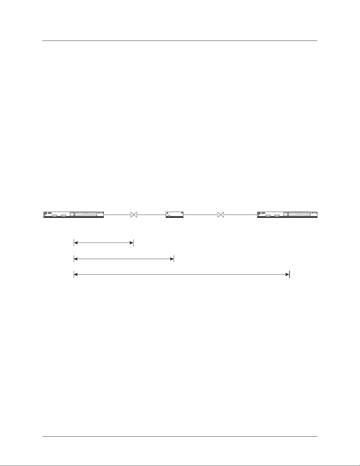
STS-1 components and SONET terminology is illustrated in Figure 1-1.
A
N
A
P
C
E
L
R
T
T
M
F
Multiplexer MultiplexerAdd/Drop
Repeater Repeater
A
N
A
P
C
E
L
R
T
T
M
F
Multiplexer
SECTION (single run of fiber)
LINE (between multiplexers)
PATH (end-to-end)
Figure 1-1. MX2800 STS-1 Components
STS-1 Framing Structure
The STS-1 frame is organized as 9 rows by 90 columns of bytes. See Table 1-1. This frame is transmitted
row by row, from left to right, and with the most significant bit (MSB) of each byte transmitted first. It is
defined to operate at the basic rate of 8 kHz or 125 microseconds per frame, or 8,000 frames per second at
a bit rate of 51.84 Mbps.
The frame is divided into two parts to physically segregate the layers:
• Transport Overhead
• Synchronous Payload Envelope
The first 3 columns make up the transport overhead (TOH); the remainder is the synchronous payload
envelope (SPE). The TOH has 3 rows for the section overhead (SOH) and 6 rows for the line overhead
(LOH). The SPE has one column for the path overhead (POH). The remaining 86 columns are for payload
data (49.536 Mbps).
1-2 61204659L1-1A
Page 19

MX2800 STS-1 User Manual Introduction, Section 1
STS-1 Overview
Table 1-1. STS-1 Framing Structure
TOH SPE
Rows
Column
1 through 3
H1 H2 H3 J1
1
2
3
4
5
6
7
8
9
H1 H2 H3 J1
1
2
3
4
5
6
7
8
9
H1 H2 H3 J1
1
2
3
4
5
6
7
8
9
H1 H2 H3 J1
1
2
3
4
5
6
7
8
9
Column
4 (POH)
B3
C2
G1
F2
H4
Z3
Z4
Z5
B3
C2
G1
F2
H4
Z3
Z4
Z5
B3
C2
G1
F2
H4
Z3
Z4
Z5
B3
C2
G1
F2
H4
Z3
Z4
Z5
Columns
5 through 90
STS-1
Payload
Region
STS-1
Payload
Region
STS-1
Payload
Region
STS-1
Payload
Region
Transport Overhead (TOH)
The first three columns are the TOH, which contains the overhead bytes for the Section and Line layers.
Section overhead is comprised of 9 bytes and Line overhead is comprised of 18 bytes.
STS-1 Synchronous Payload Envelope (SPE)
The SPE has 87 columns and 9 rows of bytes for a total of 783 bytes. Column 1 contains the STS Path
Overhead and has 9 bytes. The remaining 774 bytes are available for payload.
61204659L1-1A 1-3
Page 20

Section 1, Introduction MX2800 STS-1 User Manual
STS-1 Overview
Virtual Tributaries (VT)
The SPE is divided into seven virtual tributary groups, made up of 12 columns each. Smaller tributaries are
multiplexed together to form these groups. For example, there can be four VT1.5 tributaries in a VT group
or three VT2 tributaries. A VT1.5 tributary consists of three columns per STS-1 frame and has a bit rate of
1.728 Mbps, allowing transport of a T1 at 1.544 Mbps plus required overhead. A VT2 uses four columns
per STS-1 frame and has a bit rate of 2.304 Mbps, allowing transport of an E1 at 2.048 Mbps plus required
overhead.
STS-1 Pointers
There are several mechanisms that allow for timing compensation between the STS-1 and its low-speed
tributaries. The MX2800 STS-1 multiplexer uses pointer adjustments to achieve timing compensation.
Pointer adjustments allow the synchronous payload envelope (SPE) to float with respect to the SONET
frame. The pointer is contained in the H1 and H2 bytes of the path overhead (POH), and is a count of the
number of bytes that the J1 byte is away from the H3 byte, not including the transport overhead. When
timing differences exist, dummy bytes are inserted into the SPE without affecting data. The receiving end
can recover the payload since the pointer is adjusted to indicate where the payload overhead (POH) starts.
Unit Timing
The MX2800 STS-1 multiplexer allows four timing methods:
• Loop Mode
• Free-Running Mode
• External Nonrevertive Mode
• External Revertive Mode
Loop Mode
The multiplexer derives timing from the incoming STS-1 signal.
A failure in this signal, such as a loss-of-signal (LOS) or a loss-of-framing (LOF) will cause the unit to
enter Holdover (HO) mode for the duration of the receive signal defect. During HO, the unit will continue
transmitting at the same rate as the receive signal prior to entering its defect condition. Stability of the
transmit during HO is guaranteed to ± 4.9 ppm over 24 hours. The defect condition must be cleared before
LOOP time mode can be resumed.
Free-Running (FR) Mode
In this mode, an internal oscillator is used to generate transmit timing.
SONET minimum clock specification of ± 20 ppm.
FREE-RUNNING mode provides a
External Nonrevertive and Revertive Modes
EXTERNAL timing mode allows the MX2800 STS-1 to derive its transmit timing from the BITS clocks
through wire-wrap pins located on the back of the chassis. Two sources can be specified to provide external timing: a primary and a secondary source. Failure of the primary source (due to LOS or AIS) will cause
1-4 61204659L1-1A
Page 21

MX2800 STS-1 User Manual Introduction, Section 1
SNMP
the unit to switch to the secondary source, if available. When in External Nonrevertive timing mode, the
timing source will not switch back to the Primary External Clock in the event that it becomes available. If
in External Revertive timing mode, the timing source will switch back to the Primary External Clock if it
becomes available. In the event that both the primary and secondary sources are lost, the unit will enter
Holdover mode as described previously . Holdover mode will be exited upon recovery of at least one clock
source.
3. SNMP
The embedded SNMP feature of the MX2800 STS-1 allows the unit to be accessed and controlled by a
network manager through the 10Base-T local area network (LAN) port. The MX2800 STS-1 supports the
MIB-II standard, RFC 1213, RFC 1595, and the ADTRAN Enterprise Specific MIB.
NOTE
MIB files are available from ADTRAN in the support section of the
ADTRAN Website at www.adtran.com.
The term SNMP broadly refers to the message protocols used to exchange information between the
network management system (NMS) and the managed devices, as well as to the structure of device
management databases. SNMP has three basic components:
•Network manager
•Agent
•MIB
Network Manager
The network manager is a set of control programs that collect, control, and present data pertinent to the
operation of the network devices. These programs reside on a network management station.
Agent
The agent is a control program that resides in every network device. This program responds to queries and
commands from the network manager, returns requested information or invokes configuration changes
initiated by the manager, and sends unsolicited traps to the manager.
MIB
A MIB is an industry standard presentation of all status and configuration parameters supported by a
network device.
61204659L1-1A 1-5
Page 22
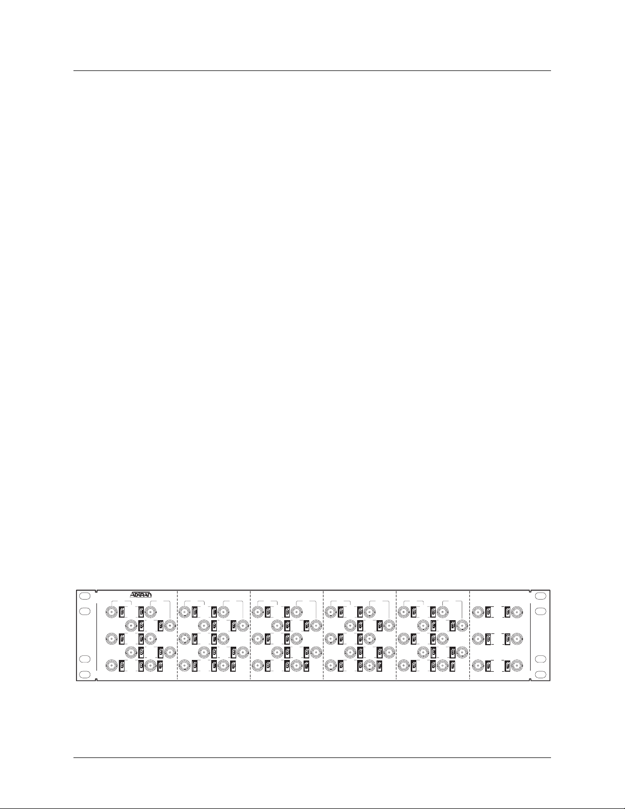
Section 1, Introduction MX2800 STS-1 User Manual
Telnet
4. TELNET
Telnet provides a password-protected, remote login facility to the MX2800 STS-1 that allows a remote
user to control the MX2800 STS-1 through the terminal menus. Only one Telnet menu session may be
active at a time.
5. TL1
Transaction Language 1 (TL1) is an ASCII based language that supports both command-response and
autonomous (NE) message generation. Commonly, TL1 is used over a X.25 packet network but is
completely independent of any physical layer protocols. For the MX2800 STS-1, TL1 is implemented as a
Telnet session running over either Ethernet or PPP. Up to eight TL1 Telnet connections may be active at a
time.
6. AVAI LABLE OPTIONS
The following optional equipment is available for use with the MX2800 STS-1. Contact a local distributor
or the ADTRAN sales department for more information.
Breakout Panel (P/N 1200291L1)
The optional breakout panel connects to the MX2800 STS-1 and provides 28 RJ connectors for the individual T1s/E1s. Shipment includes two six-foot, 64-pin to 64-pin amphenol cables which allow direct cabling
to the MX2800 STS-1 (refer to Connecting the Breakout Panel on page 2-5 for more information).
BNC Patch Panel (P/N 1200291L5)
The optional BNC Patch Panel connects to an MX2800 Chassis or equivalent and is mountable to a
19-inch rack. The panel converts the T1/E1 transmit-and-receive signal interfaces from 120-ohm amphenol interfaces to 75-ohm coaxial (BNC). This allows easy 75-ohm impedance-matched access to both the
transmit and receive lines of each T1/E1 channel. Each of the twenty eight BNC interfaces is configurable
as either balanced or unbalanced. The frame ground of the patch panel is connected to a ground lug accessible on the rear of the patch panel. See Figure 1-2.
ON ON
ON ON
ON
TX RX
OPEN
CH 26
ON ON
EARTH
OPEN
CH 27
ON ON
EARTH
OPEN
CH 28
ON ON
EARTH
TX RX
OPEN
CH 1
ON ON
EARTH
OPEN
CH 2
EARTH
OPEN
CH 3
ON ON
EARTH
OPEN
CH 4
EARTH
OPEN
CH 5
ON ON
EARTH
ON ON
ON ON
ON
TX RX
OPEN
CH 6
ON ON
EARTH
OPEN
CH 7
EARTH
OPEN
CH 8
ON ON
EARTH
OPEN
CH 9
EARTH
OPEN
CH 10
ON ON
EARTH
ON ON
ON ON
ON
TX RX
OPEN
CH 11
ON ON
EARTH
OPEN
CH 12
EARTH
OPEN
CH 13
ON ON
EARTH
OPEN
CH 14
EARTH
OPEN
CH 15
ON ON
EARTH
ON ON
ON ON
ON
TX RX
OPEN
CH 16
ON ON
EARTH
OPEN
CH 17
EARTH
OPEN
CH 18
ON ON
EARTH
OPEN
CH 19
EARTH
OPEN
CH 20
ON ON
EARTH
ON ON
ON ON
ON
TX RX
OPEN
CH 21
ON ON
EARTH
OPEN
CH 22
EARTH
OPEN
CH 23
ON ON
EARTH
OPEN
CH 24
EARTH
OPEN
CH 25
ON ON
EARTH
Figure 1-2. Optional BNC Patch Panel
1-6 61204659L1-1A
Page 23
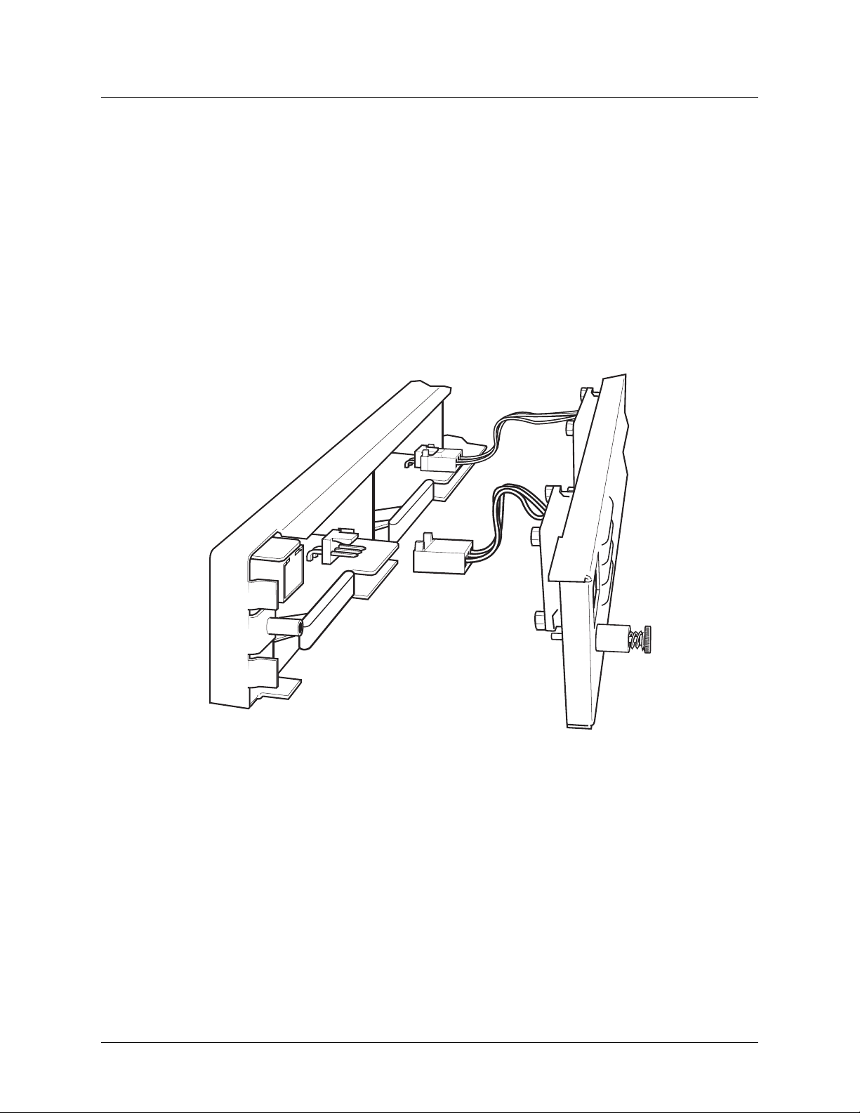
MX2800 STS-1 User Manual Introduction, Section 1
Available Options
Battery Backup (P/N 4175043L2)
The battery backup system provides power backup in the event of power loss. This system includes the
battery, an AC battery charger, and an alarm cable.
Fan Faceplate (P/N 1200466L1)
The MX2800 Fan Faceplate provides the means for additional heat dissipation. This allows multiple units
to be stacked directly on top of each other . The fan faceplate replaces the original faceplate, and it is for use
with the 1202289L1, 1202289L2, and 1202289L3 power sup plies. Figure 1-3 shows how the fan faceplate
is installed on the chassis.
Figure 1-3. Fan Faceplate
61204659L1-1A 1-7
Page 24

Section 1, Introduction MX2800 STS-1 User Manual
Available Options
This page is intentionally blank.
1-8 61204659L1-1A
Page 25

SECTION 2, INSTALLATION AND OPERATION
Section 2
Installation and Operation
1. INTRODUCTION
The first three tasks for installing and operating the MX2800 are to unpack, inspect, and power up. The
next three subsections detail the tasks. Additional subsections provide information for mounting the
MX2800 into an equipment rack, making the proper connection to the back panel, identifying the front
panel indicators and modular jack, and the adding or removing of a card.
2. RECEIVING INSPECTION
Carefully inspect the MX2800 for any damage that might have occurred in shipment. If damage is
suspected, file a claim immediately with the carrier, keep the original packaging for damage verification
and/or returning the unit, and contact ADTRAN Customer Service. For warranty information, refer to
Appendix F, Warranty.
3. ADTRAN SHIPPING CONTENTS
After unpacking the MX2800 unit but before an initial power up, be sure that the following items are
present:
• MX2800 unit
• DC or AC power supply (two power supplies come with the redundant versions)
• Controller card (two cards come with the redundant versions)
• 8-pin to 6-pin modular cable (modem version only)
• 8-pin to 8-pin modular cable
• 8-pin modular to DB-9 female connector
• Two 4-position terminal lug connectors
• 3-position ter minal lug connector
• Six-foot AC power cable (AC version only)
• Mounting brackets and screws for 19-inch or 23-inch rack installation
• MX2800 STS-1 System Manual on Compact Disk
• MX2800 STS-1 Job Aid
61204659L1-1A 2-1
Page 26

Section 2, Installation and Operation MX2800 STS-1 User Manual
Power Up
NOTE
MIB files are available from ADTRAN in the support section of the
ADTRAN website at www.adtran.com.
4. POWER UP
The AC version of the MX2800 is provided with a 6-foot power cable terminated in a three-prong plug
which is connected to a grounded 120 VAC power receptacle.
NOTE
Power to the AC version of the MX2800 must be provided from a
grounded 120 VAC power receptacle.
The DC version of the MX2800 is provided with two 4-position modular terminal lug connectors. These
connectors simplify the initial wiring and connection or disconnection of the DC power when replacing
rackmount units.
NOTE
A 3-amp fuse is recommended for use in the fuse and alarm panel that
feeds the MX2800.
For more detailed information on power connections, refer to Section 8, Power Loss Recovery on
page 8-1.
Once the modular connector is wired, push it firmly into one of the rear panel power connectors. Figure
2-1 and Table 2-1 illustrate the DC power connector and give definitions for the four connector symbols.
NOTE
The chassis should be connected to an earth ground using the ground stud
located between the AC and DC power sources on the rear panel.
2-2 61204659L1-1A
Page 27
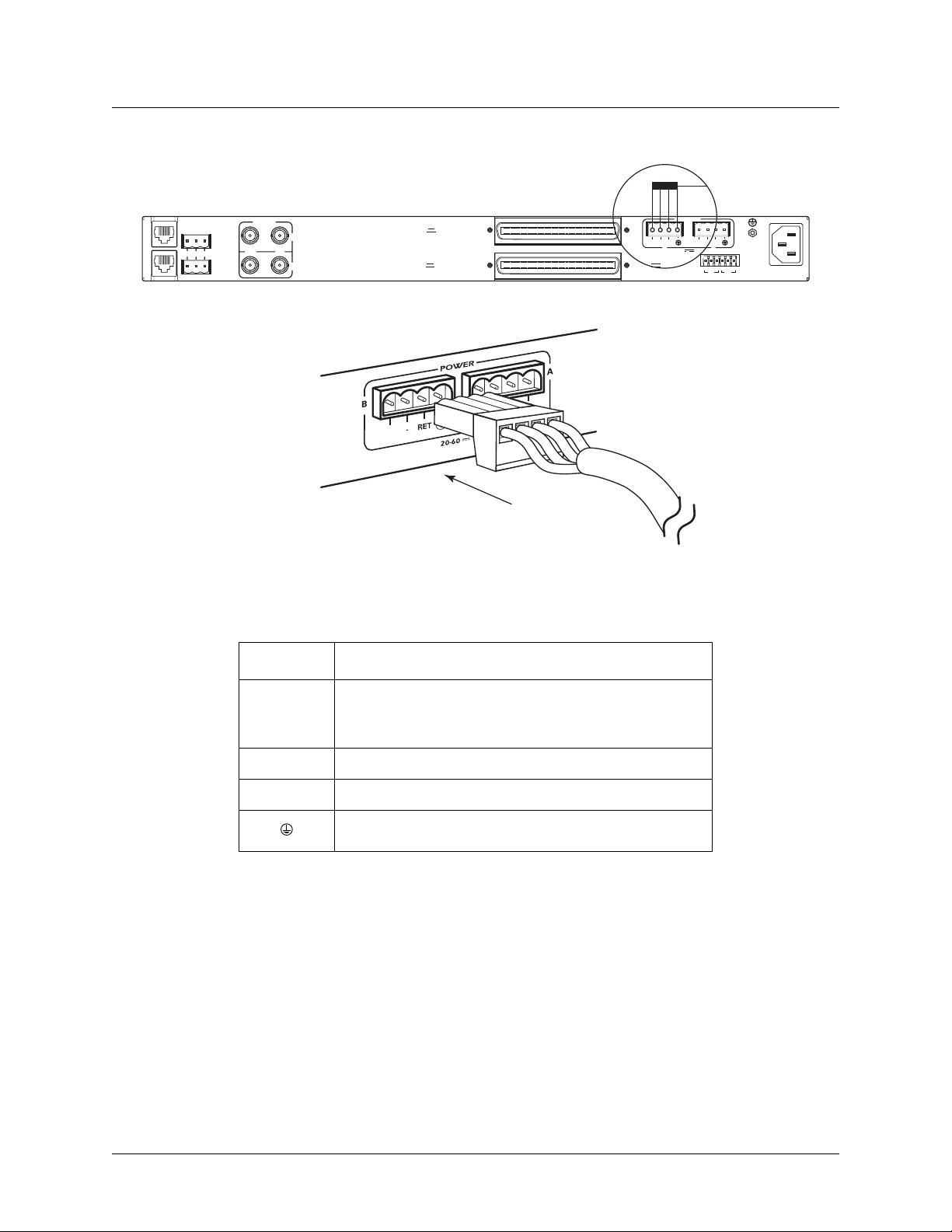
MX2800 STS-1 User Manual Installation and Operation, Section 2
Power Up
L
NONCRITICAL
A
N
M
NO COM NC
O
D
E
M
CRITICAL
DS3/STS-1
OUT IN
A
B
PWR
L
FAI
DSX-1/E1
(OUT)
DSX-1/E1
(IN)
DC POWER
PWR
PWR
FAIL
–
–
B
RET
-48V 0.7A
FAIL
RET
A
TRSTR
CLKACLK
B
115 AC 50/60Hz
0.8A
USE COPPER
CONDUCT ORS ONLY!
S
Figure 2-1. DC Power Connector
Table 2-1. DC Connector Symbol Definitions
Symbol Definition
PWR FAIL
Battery backup connector. If the AC fails , a trap is sent to
as notification when connected to the 4175043L2 battery
backup or equivalent system.
–
RET
Negative side of DC power source (usually –48 VDC)
Positive side of DC power source (usually ground)
Frame Ground
The following UL requirements must be met during installation of the MX2800 DC version:
1. Disconnect all power sources prior to servicing. Unit may use multiple power sources.
2. Voltage input requirement for DC version is Minimum –48 VDC, 0.8 amps
3. Voltage input requirement for AC version is Minimum 120 VAC, 0.32 amps
4. Connect to a reliably grounded –48 VDC source wh ich is electrically isolated from the AC source. Use
24 VDC source for 1202289L3.
5. The branch circuit overcurrent protection must be a fuse or circuit breaker rated minimum 48 VDC,
maximum 20 amps.
61204659L1-1A 2-3
Page 28

Section 2, Installation and Operation MX2800 STS-1 User Manual
Rackmount Installation
6. A readily accessible disconnect device that is suitably approved and rated must be incorporated in the
field wiring.
7. The chassis should be connected to an earth ground using the ground stud located between the AC and
DC power sources on the rear panel.
8. The unit must be installed in accordance with the requirements of NEC NFPA 70.
9. The unit must be installed in accordance with Articles 400 and 364.8 of the National Electrical Code
NFPA 70 when installed outside of a restricted access location (that is, in a Central Office, behind a
locked door, or in an area accessed by service personnel only).
10. Care should be taken not to upset the stability of the equipment rack after installation is complete.
CAUTION
Use copper conductors only for DC power and ground connection.
5. RACKMOUNT INSTALLATION
The MX2800 STS-1 can be mounted into a standard 19-inch or 23-inch equipment rack. Follow these steps
to mount the unit into a rack:
1. Install the mounting flanges on each side of the MX2800 STS-1 at one of the three available positions.
CAUTION
Install the flanges only with the screws provided.
2. After the flanges have been installed, position the MX2800 STS-1 at the correct location within the
rack and secure the mounting flanges to the mounting rails of the rack.
3. Make all network, DTE, and power connections to the rear of the unit. Refer to Power Up on page 2-2
for more information on making the DC power connection.
4. Using the 8-position modular to DB-9 female connector and the 8-position modular to 8-position
modular cable, connect a VT 100 terminal device to the
CRAFT port on the front panel of the unit.
NOTE
Two MX2800 STS-1s may be stacked with no spacing between units.
ADTRAN recommends 1U (1.75") of separation above and below the
two stacked units. This spacing allows the unit to dissipate heat. The
design of the MX2800 STS-1 uses the chassis to distribute heat generated
by the internal cards. This arrangement allows the unit to operate without
a cooling fan.
2-4 61204659L1-1A
Page 29
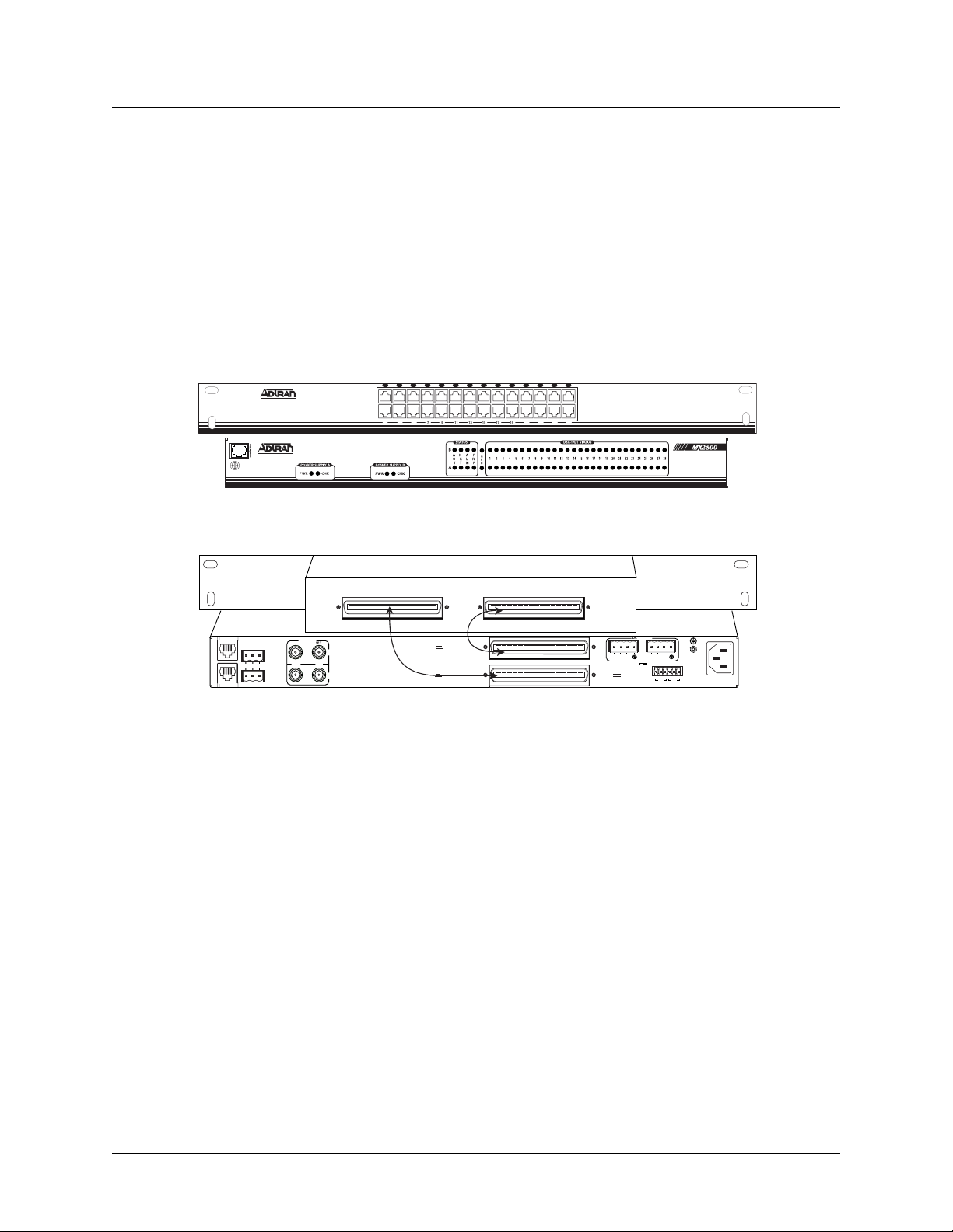
MX2800 STS-1 User Manual Installation and Operation, Section 2
Rear Panel
Connecting the Breakout Panel
The optional breakout panel (P/N 1200291L1) connects to the MX2800 STS-1 via the IN and OUT amphenol connectors located on the back of the unit, and provides 28 RJ connectors for the individual T1s/E1s.
Shipment includes two six-foot, 64-pin to 64-pin amphenol cables which allow direct cabling to the
MX2800 STS-1. Connect the
the MX2800 STS-1. Connect the
IN amphenol connector of the breakout panel to the IN amphenol connector of
OUT amphenol connector of the breakout panel to the OUT amphenol
connector of the MX2800 STS-1 (see Figure 2-2).
Front View
2 4 6 8 10 12 14 16 18 20 22 24 26 28
1 3 5 7 9 11 13 15 17 19 21 23 25 27
N
A
P
A
E
L
R
C
T
M
F
T
Rear View
IN OUT
DS3/STS-1
OUT IN
NET
A
B
Cable 1
L
NONCRITICAL
A
N
M
NO COM NC
O
D
E
M
CRITICAL
DSX-1/E1
(OUT)
DSX-1/E1
(IN)
Cable 2
DC POWER
PWR
PWR
FAIL
–
B
RET
-48V 0.7A
FAIL
–
RET
A
TRSTR
CLKACLK
115 AC 50/60Hz
0.8A
USE COPPER
CONDUCTORS ONLY!
S
B
Figure 2-2. The Breakout Panel
Connecting the BNC Patch Panel
The optional BNC patch panel (P/N 1200291L5) connects to the MX2800 via the TX and RX amphenol
connectors located on the back of the unit and provides 28 pairs of BNC connectors for the individual
T1/E1s. Shipment includes two 6-foot, 64-pin to 64-pin amphenol cables for direct cabling to the MX2800.
Connect the BNC patch panel
BNC patch panel
TX amphenol connector to the MX2800 OUT amphenol connector.
RX amphenol connector to the MX2800 IN amphenol connector and the
6. REAR PANEL
The MX2800 STS-1 rear panel is equipped as follows:
• LAN port
•Modem port
• Two alarm output terminal blocks
61204659L1-1A 2-5
Page 30
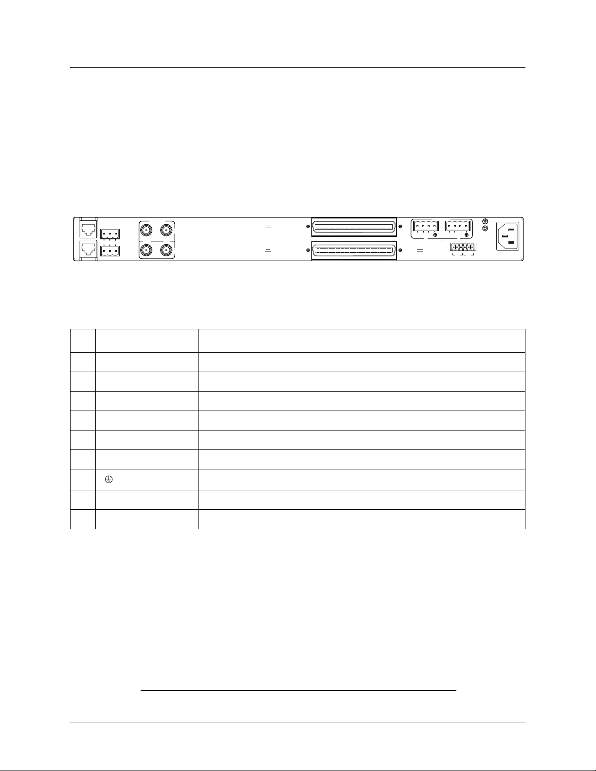
Section 2, Installation and Operation MX2800 STS-1 User Manual
Rear Panel
• Two sets of NET in/out jacks
• Two amphenol connectors
• DC/AC power connections
• Wire-wrap pins for external connection of BITS clock
Descriptions for the items shown in Figure 2-3 are explained in Table 2-2. Pin assignments are given in
the tables in Appendix B, Pinouts.
L
NONCRITICAL
A
N
1
M
O
D
E
2
M
3
NO COM NC
CRITICAL
DS3/STS-1
OUT IN
A
4
B
DSX-1/E1
(OUT)
DSX-1/E1
(IN)
PWR
–
5
FAIL
Figure 2-3. MX2800 STS-1 Rear View
Table 2-2. MX2800 Review View Identifiers
# Item Function
1 Ethernet LAN 10Base-T Ethernet connection
2 Modem Telephone line connection for internal V.34
3 Noncritical/Critical Connections for external audible/visual alarms
4 DS3/STS-1 EC-1/STS-1 service connection for controller cards A and B
5 DSX-1/E1 64-pin female amphenol connectors for T1/E1s
6 Power DC power connection
7 Ground stud
RET
B
DC POWER
PWR
FAIL
6
-48V 0.7A
–
RET
A
TRSTR
CLKACLK
115 AC 50/60Hz
0.8A
7
USE COPPER
8
CONDUCTORS ONLY!
S
B
9
8 115 VAC 50/60 Hz AC power connection
9 BITS Clock Wire-wrap pins for external connection of BITS clocks
LAN Port
The LAN port is an 8-pin modular connector that provides a 10Base-T ethernet LAN interface. This LAN
interface is used for SNMP and Telnet control.
NOTE
Connect the LAN port to intra-building wiring only.
2-6 61204659L1-1A
Page 31

MX2800 STS-1 User Manual Installation and Operation, Section 2
Rear Panel
Modem Port
The MODEM port is an 8-pin modular jack that provides a telephone line (POTS) connection for the internal V.34 modem.
The MX2800 STS-1 can be configured as a dial-in host and also as a dial-out-on-Trap device (meaning the
unit dials out to a specified host to report error conditions).
NOTE
Information regarding the built-in modem applies to the following
ADTRAN products:
4204659L1 AC Non-Redundant Version with Modem
4204659L2 AC Redundant Version with Modem
4204659L3 DC Non-Redundant Version with Modem
4204659L4 DC Redundant Version with Modem
4204659L10 STS-1 AC/DC Redundant with Modem
4204659L11 AC Non-Redundant with Modem with Fans
4204659L12 AC Redundant with Modem with Fans
4204659L13 DC Non-Redundant with Modem with Fans
4204659L14 DC Redundant with Modem with Fans
Noncritical and Critical Alarm Connectors
The alarm connectors connect to the three contacts of a Form C type relay on the main board of the
MX2800 STS-1. This relay is activated any time the MX2800 STS-1 detects an alarm condition on the
STS-1 network interface. Both
NC (normally closed) and NO (normally open) contacts are provided.
Connect alarms to one of the three-position modular terminal lug connectors (provided). These connectors
make it easier to perform initial wiring and to connect and disconnect alarms when replacing rackmount
units. Once a modular connector is wired, push it firmly into the rear panel
NONCRITICAL or CRITICAL
connector.
The alarm functions can be enabled or disabled through the Alarm Relays section of the Configuration
menu (refer to Alarm Relay Configuration on page 3-31).
Network Interfaces
The network interfaces are full-duplex circuits provided by four BNC coaxial cable connections. The
receive data from the network is connected to the RX (
MX2800 STS-1 is connected to the TX (
OUT) connectors.
Network interfaces must be connected using coaxial cables that have the
shields grounded at both ends.
IN) connectors, while the transmit data from the
NOTE
61204659L1-1A 2-7
Page 32

Section 2, Installation and Operation MX2800 STS-1 User Manual
Front Panel
DSX-1/E1 Interfaces
The DSX-1/E1 interfaces are 64-pin amphenol connectors. These interfaces provide Tx and Rx connections between the unit and equipment such as wire-wrap patch pan els, punch-down panels, or breakout
panels.
NOTE
Connect the DSX-1/E1 interfaces to intra-building wiring only.
Power Connection
The DC and AC power connections are described in Power Up on page 2-2.
External BITS Clock
The external BITS clock connections are made through wire-wrap pins. It is possible to connect two external BITS clocks in this manner. This allows either one or two external BITS clocks to be used for unit
timing. Each BITS clock terminates on three wire-wrap posts. The posts are tip, ring, and shield and are
labeled
T, R, and S for clock A and clock B.
7. FRONT PANEL
The MX2800 STS-1 faceplate is shown below in Figure 2-4. Descriptions of each part of the front panel
follow.
• Craft Port on page 2-8
• ACO Buttons on page 2-13
• LED Descriptions on page 2-13
A
N
A
P
C
E
L
R
T
T
M
F
Figure 2-4. MX2800 STS-1 Front Panel
Craft Port
The CRAFT port, an 8-pin modular jack, provides connection to a VT100 EIA-232 compatible interface
using the supplied 8-pin modular to DB-9 female connector and the 8-pin to 8-pin modular cable.
2-8 61204659L1-1A
Page 33

MX2800 STS-1 User Manual Installation and Operation, Section 2
Front Panel
Establishing Terminal Connection
NOTE
A Telnet menu session has priority over a terminal menu session through
the craft port. If a terminal menu session is active when a Telnet menu
session is initiated, the terminal menu session will be disabled while the
Telnet menu session is active.
To connect the MX2800 STS-1 to a VT100 terminal, follow the steps below:
1. Configure the VT100 terminal as follows:
• 9600, 19200, 38400, or 57600 baud
• 8-bit characters
•no parity
• one stop bit
2. Using the terminal interface cable adapter provided by ADTRAN, connect the DTE port of a terminal
to the 8-pin modular jack labeled
CRAFT on the MX2800 STS-1 front panel.
3. Initialize the terminal session.
4. Press
5. Enter the user name. The factory default user name is adtran (all lower-case). The
ENTER repeatedly until the username: prompt appears.
password: prompt
appears.
6. Enter the password. The factory default password is adtran (all lower-case). The Main Menu
displays (see Figure 2-5).
7. Make selections by entering the number corresponding to the chosen parameter. Press
keyboard to return to the previous screen. End a terminal session by selecting
Menu or by pressing
CTRL+C at any time.
Logout from the Main
ESC on the
61204659L1-1A 2-9
Page 34

Section 2, Installation and Operation MX2800 STS-1 User Manual
Front Panel
Figure 2-5. ADTRAN STS-1 Main Menu
NOTE
The letter displayed in the upper left-hand corner of the terminal menu
indicates which controller card is active (A or B).
Navigating Within the Menus
Navigate within the MX2800 STS-1 terminal menus using the following procedures:
To... Then...
Select an item Press the number corresponding to a choice, and then press the
E
NTER key
Scroll left and right within the same screen Press the left and right arrow keys. Additional screens are available
when < or > is displayed in the top portion of the menu
Return to the previous menu Press the E
End the terminal session Press C
Refresh the display Press C
Scroll up or down within the same screen Press the up or down arrow keys. Additional screens are available
when ∧ or ∨ is displayed in the top portion of the menu
SC key
TRL+C
TRL+R
2-10 61204659L1-1A
Page 35

MX2800 STS-1 User Manual Installation and Operation, Section 2
Front Panel
The MX2800 STS-1 Main Menu consists of the following options:
Status
This screen provides information on the current state of the STS-1, power supplies, system, and VT/Port
lines. For more detailed information, refer to Section 4, Status.
Figure 2-6. Status Screen
Statistics
This screen provides detailed statistical information (both current and historical) for the STS-1, VT, and
Port lines. For more detailed information, refer to Section 5, Statistics.
61204659L1-1A 2-11
Page 36

Section 2, Installation and Operation MX2800 STS-1 User Manual
Front Panel
Figure 2-7. Statistics Menu
Configuration
Sets STS-1 network, VT/Port, and system management parameters. For more detailed information, refer to
Section 3, Configuration.
Figure 2-8. Configuration Menu
Loopbacks
This option accesses loopback tests for the STS-1 and VT/Port circuits. For more detailed information,
refer to Section 6, Loopbacks.
2-12 61204659L1-1A
Page 37

MX2800 STS-1 User Manual Installation and Operation, Section 2
Front Panel
Figure 2-9. Loopback Menu
Logout
The Logout selection ends the terminal session and logs out of the system. The unit will also logout of a
terminal session automatically if the session remains inactive for a certain period of time. A valid
username and password entry are required to initiate a new terminal session. For more information, refer to
Terminal Timeout on page 3- 30.
ACO Buttons
The ACO (alarm cut off) buttons turn off an active audible alarm. The buttons are recessed, requiring a
pointed instrument to press them. Once an
ACO button has deactivated an audible alarm, the alarm remains
disabled for the duration of that alarm condition.
Alarms can also be turned off remotely by using a selection found in the Status menu. Refer to Acknowl-
edge Alarms (ACO) on page 4-8 for more information.
LED Descriptions
The MX2800 STS-1 has LED status indicators for the power supplies, the STS-1 state, the controller cards,
and the individual T1s/E1s. These LEDs are identified in the following subsections.
Power Supply A/B Status LEDs
The
PWR LED is active when the unit is on and receiving full power. The CHK LED is active when the
power supply is failing or is providing low power and needs to be checked.
61204659L1-1A 2-13
Page 38

Section 2, Installation and Operation MX2800 STS-1 User Manual
Front Panel
Controller Card Status LEDs
The status LEDs on the two controller cards are
ACT (active), NET (network), ALM (alarm), and PRF
(performance). Different conditions are indicated by the state of the LED (it remains solid, flashes, or alternates colors). The condition descriptions vary depending on whether the LED represents the active controller card or the controller card on standby.
LED definitions are for the active cards are provided in Table 2-3.
LED definitions for standby cards are provided in Table 2-4.
Table 2-3. LED Conditions for Active Cards
Label LED State Card Condition
ACT Green solid No rm a l (All OK)
Green/Amber alternating Normal + Console Open
Red solid Self T est Failed
Amber solid Software Update in Progress
Red/Amber alternating Self Test Failed + Console Open
Red flashing Card Failure
NET
Green solid No rm a l (All OK)
Red flashing LOS
Red solid LOMF, AIS-P, AIS-L, RFI-L, RFI-P, LOP, SLM, UEQ
Amber solid In Test (Local)
Amber flashing In Test (Remote)
Red/amber alternating In Test + Alarms
ALM Green solid Normal (No Alarm)
Red flashing Critical Alarm
Red solid Non-Critical Alarm
Amber flashing Critical Alarm Suppressed (
Amber solid Non-Critical Alarm Suppressed (
PRF Green solid Normal (All OK)
Red flash (once per event) Single/Burst CV
Red flashing Continuous Code Violations
Red solid XCV Threshold Exceeded
ACO button was pushed)
ACO button was pushed)
2-14 61204659L1-1A
Page 39

MX2800 STS-1 User Manual Installation and Operation, Section 2
Front Panel
Table 2-4. LED Conditions for Standby Cards
Label
ACT Green flashing Normal (All OK)
LED State Card Condition
Amber solid Software Update in Progress
Red flashing Self Test Failed
NET Off Normal (All OK)
Red flashing STS-1 Failure
ALM Off Normal (No Alarm)
PRF Off Normal (All OK)
T1/E1 Status LEDs
These LEDs apply to each individual T1 or E1. Different conditions are indicated by the state of the LED
(its color and whether it flashes, alternates color, or remains solid). The condition descriptions vary
depending on whether the LEDs represent T1s or E1s of the active controller card or the controller card on
standby. Table 2-5 provides T1/E1 LED definitions for the active and standby card.
Table 2-5. T1/E1 Status LEDs
LED State T1/E1 Condition
Active Card Green solid Normal (All OK)
Off Disabled
Red flashing LOS
Red flash (once per event) Single/Burst CV
Red/green alternating XCV Threshold Exceeded
Amber solid In Test (Local)
Amber flashing In Test (Remote)
Red/amber alternating In Test + Alarm
Standby Card Off Normal (All OK) or
N/A (in the case of E1 configuration)
Red flashing T1/E1 Failure
61204659L1-1A 2-15
Page 40

Section 2, Installation and Operation MX2800 STS-1 User Manual
C A U T I O N
Replacing or Installing Cards
8. REPLACING OR INSTALLING CARDS
The MX2800 STS-1 is designed with hot-swappable controller cards and power supplies. To replace or
install a controller card or power supply, the front cover must be removed.
Cover Removal
C A U T I O N
SUBJECT TO ELECTROSTATIC DAMAGE
OR DECREASE IN RELIABILITY.
HANDLING PRECAUTIONS REQUIRED.
!
Remove the front cover of the MX2800 STS-1 with a phillips-head screwdriver. With the cover removed,
the power supply and controller card slots will be visible.
Module Replacement
The two power supplies are located at the left of the chassis
The controller cards are stacked on the right side of the chassis.
To remove a card, pull the locking lever for the desired card to separate the backplane connector from the
backplane. Once, the backplane connector has disconnected, carefully pull the card straight out of the
chassis.
To replace or install a card, simply line up the card with the guide grooves. Carefully insert the card into
the chassis until the backplane connector reaches the backplane.
Finally, use the locking levers to seat the card firmly into the backplane connector slot on the chassis.
Once all cards have been replaced or installed, replace the front cover of the MX2800 STS-1.
Figure 2-10 illustrates the removal and replacement of the front cover.
Figure 2-10. Replacing or Installing Cards
2-16 61204659L1-1A
Page 41

SECTION 3, CONFIGURATION
Section 3
Configuration
Configuration of the MX2800 STS-1 is accomplished via either the 10Base-T ethernet connection, a
SLIP/PPP modem port, or a VT-100 terminal. Figure 3-1 shows the Configuration menu screen. Figure
3-2, Figure 3-3, and Figure 3-4 show the menu tree.
NOTE
A Telnet menu session has priority over a terminal menu session through
the craft port. If a terminal menu session is active when a Telnet menu
session is initiated, the terminal menu session will be disabled until the
Telnet menu session is closed.
Figure 3-1. Configuration Menu
Detailed descriptions of the menu options shown in Figure 3-1 are given in the following:
• Network Interface on page 3-5
• VT Interface on page 3-9
• System Management on page 3-16
• Utilities on page 3-37
• Save Configuration and Alarm Log on page 3-43
61204659L1-1A 3-1
Page 42

Section 3, Configuration MX2800 STS-1 User Manual
Network Interface
STS-1 Configuration
Protection Configuration
Miscellaneous
External Clock Configuration
Line Length
Timing
XCV Threshold
VT Mode
Active Controller
Network Protection
Max Switch Threshold (3*)
Min Switch Period (10 Sec.*)
Loopback Time Out
PRI External Clock
SEC External Clock
Short (0-225 ft.)*
Long (225-450 ft.)
Loop*
Free-run
External Nonrevertive
External Revertive
Disabled*
IE-3
IE-4
IE-5
IE-6
VT 1.5 (T1)*
VT 2 (E1)
A
B
Disabled*
Enabled
Disabled
1 min.
5 min.*
10 min.
15 min.
30 min.
45 min.
1 hour
Disabled*
External A
Disabled*
External B
VT Interface
System Management
Utilities
Save Configuration & Alarm Log
B
C
Load Default Settings
Update FLASH Software
Configuration Transfer
System Reset
Via XMODEM
Update via TFTP Server
* = default settings
Figure 3-2. Configuration Menu Tree, Page 1
3-2 61204659L1-1A
Page 43

MX2800 STS-1 User Manual Configuration, Section 3
B
VT Interface
* = default settings
VT #1-28
Set Multiple
Set Cross-Connect Mapping
Protection Threshold (1*)
XCV Threshold
VT Port Mapping
T1 State
T1 Coding
T1 Line Length
T1 Remote Loopback
T1 Circuit Protection
Hairpin Loopback
Line ID
First
Last
State
Line Coding
T1 Line Length
Circuit Protection
Loopback Detection
Apply State
Apply Line Coding
Apply Line Length
Apply Circuit Protection
Apply Loopback Protection
Apply All
VT #1-28
Set Multiple
Disabled*
IE-3
IE-4
IE-5
IE-6
Disabled
Enabled
Auto Enable*
AMI
B8ZS*
0-133 ft.*
133-266 ft.
266-399 ft.
399-533 ft.
533-655 ft.
-7.5 dB
Disabled
CSU*
NIU
Disabled
Enabled*
Disabled*
Enabled
Disabled
Enabled *
Auto Enable
AMI
B8ZS/HDB3*
0-133 ft.*
133-266 ft.
266-399 ft.
399-533 ft.
533-655 ft.
-7.5 dB
Disabled
Enabled*
Disabled
CSU*
NIU
Set VT Sequential Mapping
Set VT Group Mapping
Figure 3-3. Configuration Menu Tree, Page 2
61204659L1-1A 3-3
Page 44

Section 3, Configuration MX2800 STS-1 User Manual
System Management
C
Mgmt Options
SNMP Mgmt Option
System Security
Local IP Address
Gateway IP Address
Subnet Mask
Management Port
Dial-up Options
Trap IP Address
Trap Generation
Read Community Name
Write Community Name
Trap Community Name
User Account Management
Terminal Timeout
IP Security
IP Hosts
LAN
MODEM
BOTH
Primary Phone Number
Secondary Phone Number
Init String
Dial String
Maximum redial attempts
Idle timeout
Connection timeout
Pause between calls
Dialout on trap
Answer on ring
Modem Mode
Modem Baud Rate = 38400 *
Hangup
STS-1 Traps
VT/Port Traps
System Traps
Power Supply Traps
MIB II Standard Traps
Disabled *
Enabled
Disabled *
Enabled
VT-100
SLIP
PPP
Date & Time
Miscellaneous
* = default settings
Date
Time
Alarm Relay Configuration
Equipment Identification
Syslog Setup
Save on Logout
Craft baud rate
STS-1 Alarms
VT/Port Alarms
System Alarms
Power Supply Alarms
Transmission
Host IP Address
Severity Level
Host Facility
Auto *
9600
19200
38400
57600
Figure 3-4. Configuration Menu Tree, Page 3
3-4 61204659L1-1A
Page 45

MX2800 STS-1 User Manual Configuration, Section 3
Network Interface
1. NETWORK INTERFACE
Select Network Interface to access the network configuration parameters (Figure 3-5). Configure the
MX2800 STS-1 network settings appropriately for the application.
Figure 3-5. Network Configuration Menu
Menu-option descriptions are described in the following sections:
• STS-1 Configuration on page 3-5
• Protection Co nfiguration on page 3-7
• Miscellaneous on page 3-8
• External Clock Configuration on page 3-8
STS-1 Configuration
Use the STS-1 Configuration selections described below to configure the STS-1 network settings to match
an application.
Line Length
Set the line length to reflect the physical length of the STS-1 network line, as follows:
• Set the line length to
• set it to
Short if the distance is less than 225 feet
Long if the cabling distance is between 225-450 feet
Timing
This option determines the source of timing used to derive the transmit signal. The MX2800 STS-1 has
four modes of timing operation:
61204659L1-1A 3-5
Page 46

Section 3, Configuration MX2800 STS-1 User Manual
Network Interface
•Loop
• Free-Run
• External Nonrevertive
• External Revertive
Loop
Loop timing configures the unit to recover timing from the STS-1 receive signal. Loss of the STS-1 receive
signal or reception of AIS causes the unit to enter hold-over mode (refer to Loop Mode on page 1-4 for
information on hold-over mode). The STS-1 receive signal must be valid for at least 10 seconds for the unit
to exit hold-over mode and restore loop timing.
Free-Run
When the unit is configured for Free-Run timing mode, timing is derived from a +/–20 ppm internal reference providing a SONET Minimum Clock (SMC).
External Nonrevertive
Setting the unit to External Nonrevertive or External Revertive timing mode configures the unit to derive
timing from one of the two external sources selected in the Primary External Clock (
ary External Clock
(Sec Ext) options. These are external BITS clocks that may be terminated on the two
PRI Ext) and Second-
sets of wire-wrap pins on the back of the MX2800 chassis. The external clock source may be disabled (if
only one source exists, or no external clock sources are desired). When both sources are configured, failure
of one source causes the unit to switch to the other source (if it is a valid source).
When in External Nonrevertive timing mode, the timing source does not switch back to the Primary external clock in the event that it becomes available.
External Revertive
When in External Revertive timing mode, the timing source switches back to Primary External clock if it
becomes available.
Failure of both sources causes the unit to enter hold-over mode. At least one external clock source must be
valid for at least 10 seconds for the unit to exit hold-over mode and restore external clock timing.
XCV Threshold
The XCV Threshold (excessive code violations threshold) sets a limit on code violations accepted by the
unit before it switches controller cards. If set to Disabled, code violations do not cause the unit to switch
controller cards. The threshold limits are described in the following chart:
Setting The unit switches controller cards if...
-3
1E
1E
1E
1E
-4
-5
-6
more than one out of every 1,000 bits received on the STS-1 contains a code violation
more than one out of every 10,000 bits received on the STS-1 contains a code violation
more than one out of every 100,000 bits received on the STS-1 contains a code violation
more than one out of every 1,000,000 bits received on the STS-1 contains a code violation
3-6 61204659L1-1A
Page 47

MX2800 STS-1 User Manual Configuration, Section 3
Network Interface
VT Mode
The seven VT groups may be configured to carry either VT1.5 or VT2 tributaries.
• When set for VT1.5 (T1), all VT groups are set for VT1.5[TU=11] at 1.728 Mbps and the ports are set
for T1 at 1.544 Mbps.
• When set for VT2 (E1), all the VT groups are set for VT2[TU=12] at 2.304 Mbps and the ports are set
for E1 at 2.048 Mbps. When set for VT2, the last 7 VTs (VT 22-28), and the last 7 ports (ports 22-28)
become unavailable.
Protection Configuration
The MX2800 STS-1 houses two controller cards for 1:1 protection against hardware failu re. The two cards
can also provide network protection, supporting two STS-1 circuits simultaneously. The menu selections
allow customization of setup parameters.
Active Controller
This field displays
controller cards to switch. For example, if controller card
A or B, indicating the active controller card. This setting can be used to force the
A is active and B is selected, a switch-over
occurs immediately.
Network Protection
This option allows enabling or disabling of the ability to automatically route the STS-1 to the backup facility in the event of a facility failure.
• Network Protection =
Enabled: All information is automatically routed to the backup facility in the
event of a primary facility failure.
• Network Protection =
Disabled: The primary STS-1 facility (A) is utilized at all times.
NOTE
When choosing a setting for Network Protection, cabling and network
provisioning issues must be considered. For configuration examples of
the different modes of protection, refer to Section 7, Circuit Redundancy.
Max. (Maximum) Switch Threshold
The value entered in this field determines the number of times per hour the unit is allowed to switch
between controller cards. If protection switching occurs more than the Max. Switch Threshold within one
hour, the unit issues a trap and inhibits automatic protection switching for the next 24 hours. The default
setting is 3 times an hour. This count may be cleared by clearing protection switch alarm counts (refer to
Protection Switch Statistics on page 5-13).
61204659L1-1A 3-7
Page 48

Section 3, Configuration MX2800 STS-1 User Manual
Network Interface
Min. (Minimum) Switching Period
After a protection switch occurs, the number of seconds entered in this field must pass before another
automatic protection switch is allowed. The default setting is 10 seconds.
Miscellaneous
Loopback Timeout
This option applies for all types of loopbacks and pattern generation tests. Any diagnostic test will expire
independently for each facility according to this option. The default setting is 5 minutes.
Sets the loopback timeout to one of the following values: Disabled, 1 minute, 5 minutes, 10 minutes,
15 minutes, 30 minutes,
45 minutes, 1 Hour
External Clock Configuration
PRI Ext. Clock and SEC Ext. Clock - These options allow selection of the primary and secondary external
clock sources among the external BITS clocks that terminate on the two sets of wire-wrap pins on the back
of the MX2800 STS-1 chassis. If a clock source detects AIS or LOS, the clock becomes invalid. The clock
will be revalidated when the AIS or LOS condition is removed.
3-8 61204659L1-1A
Page 49

MX2800 STS-1 User Manual Configuration, Section 3
VT Interface
2. VT INTERFACE
The VT Interface menu (shown in Figure 3-6) provides the following functions:
• VT Interface #1-28 on page 3-9
• Set Multiple on page 3-11
• Set Cross-Connect Mapping on page 3-12
• Protection Threshold (1-28) on page 3-16
• XCV Threshold on page 3-16
Figure 3-6. VT Interface Menu
VT Interface #1-28
The VT Interface #1-28 menu (Figure 3-7) allows the management of the following functions:
• VT # Map on page 3-10
• T1/E1 S tate on page 3-10
• T1/E1 Codin g on page 3-10
• T1/E1 Line Length on page 3-10
• T1 Remote Loopback on page 3-10
• T1/E1 Circuit Protection on page 3-11
• Hairpin Loopback on page 3-11
• Line ID on page 3-11
61204659L1-1A 3-9
Page 50

Section 3, Configuration MX2800 STS-1 User Manual
VT Interface
Figure 3-7. Configure VT Interface #1 Menu
VT # Map
Map a T1/E1 port of the VT selected in the VT Interface Menu to a VT. Any available T1/E1 port can be
mapped to an available VT. An error is returned if the port is already mapped to another VT. Select
Unequipped to unmap a VT.
T1/E1 State
Set T1/E1 as Disabled, Enabled, or Auto Enable. In Auto Enable, the unit automatically detects when a
T1/E1 signal is connected and begins to allow alarm reporting for that channel.
T1/E1 Coding
Set the line code for each individual T1/E1 interface to match the connected device.
• T1 line code choices are AMI and B8ZS
• E1 line code choices are AMI and HDB3
T1/E1 Line Length
Set the line length for each T1 interface according to the distance from the MX2800 to a DTE device.
• Options are available for T1 channels for up to 655 feet
• The only available opti on for an E1 chan nel is
0-6 dB loss
T1 Remote Loopback
Allows a selected T1 to respond to CSU or NIU loopbacks arriving from the STS-1 side. This option is not
supported for E1.
3-10 61204659L1-1A
Page 51

MX2800 STS-1 User Manual Configuration, Section 3
VT Interface
T1/E1 Circuit Protection
T1/E1 Circuit Protection determines which circuit initiates a protection switch if a failure in the circuitry
for that channel is detected.
• If set to Disabled, the failure of the circuitry of that one channel does not cause a protection switch.
• If set to Enabled, the failure of a channel causes a protection switch to occur (depending on the
Protection Threshold setting).
Hairpin Loopback
This option allows a Hairpin loopback of the VT to the STS-1 signal for dropping further down the
SONET ring.
Line ID
Text strings may be entered to name the individual T1 lines. This field accepts up to 18 alpha-numeric
characters, including spaces and special characters (such as an underbar).
Set Multiple
The Set Multiple option displays the menu shown in Figure 3-8, which is used to make multiple changes
to the state, line coding, length, circuit protection, and loopback detection.
These may be set as a contiguous group, or to all VTs at one time.
All VTs
Make changes to all VTs with the follo wing steps:
1. Set
2. Make the necessary changes
3. Select
4. Exit the menu if work is complete
Contiguous Group
Make changes to some of the VTs within a contiguous group by following these steps:
1. Set the
2. Select
3. Exit the menu, or continue to enter new First and Last numbers for other lines. Apply the settings
First to 1 and Last to 28
Apply All (or select the Apply option that corresponds to the change made)
First and Last fields to correspond to the lines to change
Apply All (or select the Apply option that corresponds to the change made).
following each change.
61204659L1-1A 3-11
Page 52

Section 3, Configuration MX2800 STS-1 User Manual
VT Interface
Figure 3-8. Set Multiple Menu
Set Cross-Connect Mapping
Any VT can be cross-connect mapped to any available T1/E1 port.
NOTE
Select Unequipped to unmap the port and disable the VT.
The Set Multiple option allows the provisioning of all available VTs as either mapped by VT group or
mapped one-to-one with the T1/E1 ports. The default mapping scheme is by VT Group.
The Set Cross-Connect Mapping menu is illustrated in Figure 3-9.
3-12 61204659L1-1A
Page 53

MX2800 STS-1 User Manual Configuration, Section 3
VT Interface
Figure 3-9. Set Cross-Connect Mapping Menu
As shown in Figure 3-9, VT #1 is mapped to Port #1, while VT #2 is mapped to Port #5. This indicates a
group mapped mode, as described in the next subsection.
The following tables illustrate the association of the VT ports and physical DS1 ports both sequentially-mapped and group-mapped.
61204659L1-1A 3-13
Page 54

Section 3, Configuration MX2800 STS-1 User Manual
VT Interface
VT1.5 Mode
When the MX2800 STS-1 system is provisioned for VT1.5 (T1) mode, each of the seven VT groups is
configured to carry four VT1.5s (1.728 Mbps each), for a total of 28 VT1.5s. Any VT1.5 may be mapped
to any of the 28 physical DS1 ports not already mapped. The diagram below illustrates how the VT1.5s are
associated with the physical DS1 ports for VT1.5 mapping both by VT group and sequentially.
Table 3-1 illustrates VT1.5 (T1) Mode.
Table 3-1. VT1.5 Mode Cross-Connect Mapping
Physical Port
Sequential-mapping
(TR-253)
Physical Port
Group-mapping
(M13)
VT 1.5 # VTG-VT
1111-1VTG #1
8281-2
15 3 15 1-3
22 4 22 1-4
2522-1VTG #2
9692-2
16 7 16 2-3
23 8 23 2-4
3933-1VTG #3
10 10 10 3-2
17 11 17 3-3
24 12 24 3-4
41344-1VTG #4
11 14 11 4-2
18 15 18 4-3
25 16 25 4-4
51755-1VTG #5
12 18 12 5-2
19 19 19 5-3
26 20 26 5-4
62166-1VTG #6
13 22 13 6-2
20 23 20 6-3
27 24 27 6-4
72577-1VTG #7
14 26 14 7-2
21 27 21 7-3
28 28 28 7-4
3-14 61204659L1-1A
Page 55

MX2800 STS-1 User Manual Configuration, Section 3
VT Interface
VT2 Mode
When the system is provisioned for VT2 (E1) mode, each of the seven VT groups is configured to carry
three VT2s (2.304 Mbps each), for a total of 21 VT2s. Any VT2 may be mapped to any physical E1 port
designated 1-21 that is not already mapped. Physical E1 ports 22-28 are unequipped (not used) when the
product is configured for VT2 mode. The diagram below illustrates how the VT2s are associated with the
physical E1 ports for VT2 mapping both by VT group and sequentially.
Table 3-2 illustrates VT2 (E1) Mode.
Table 3-2. VT2 Mode Cross-Connect Mapping
Physical Port
Sequential-mapping
(TR-253)
Physical Port
Group-mapping
(M13)
VT 1.5 # VTG-VT
1111-1VTG #1
8281-2
15 3 15 1-3
2422-1VTG #2
9592-2
16 6 16 2-3
3733-1VTG #3
10 8 10 3-2
17 9 17 3-3
41044-1VTG #4
11 11 11 4-2
18 12 18 4-3
51355-1VTG #5
12 14 12 5-2
19 15 19 5-3
61666-1VTG #6
13 17 13 6-2
20 18 20 6-3
71977-1VTG #7
14 20 14 7-2
21 21 21 7-3
61204659L1-1A 3-15
Page 56

Section 3, Configuration MX2800 STS-1 User Manual
System Management
Protection Threshold (1-28)
The Protection Threshold setting determines how many of the Enabled lines must fail before a card switch
occurs. To cause the failure of a single protected (enabled) line to switch to protection, set the Protection
Threshold to 1. Choices are 1 to 28.
XCV Threshold
Set a limit on code violations (CVs) accepted by the unit over an individual T1/E1 line before it switches
controller cards. If set to Disabled, code violations do not cause the unit to switch controller cards. The
threshold limits are described in the following chart:
Setting The unit switches controller cards if...
-3
1E
1E
1E
1E
-4
-5
-6
more than one out of every 1,000 bits received on a T1/E1 line contains a code violation
more than one out of every 10,000 bits received on a T1/E1 line contains a code violation
more than one out of every 100,000 bits received on a T1/E1 line contains a code violation
more than one out of every 1,000,000 bits received on a T1/E1 line contains a code violation
3. SYSTEM MANAGEMENT
System management is possible through either SNMP, TL1, or VT-100 menus. Access is possible via craft
port, SLIP/PPP modem port, or 10Base-T ethernet interface. The menu (Figure 3-10) includes options to
customize alarm and trap generation, security setup, and equipment identification. The availability of some
options in this menu vary depending upon the configuration of other options.
Figure 3-10. System Management Configuration Menu
3-16 61204659L1-1A
Page 57

MX2800 STS-1 User Manual Configuration, Section 3
System Management
CAUTION
Configuration changes to Local IP Address, Gateway IP Address, Subnet
Mask, Management Port, Modem Mode, Modem Baud Rate, and IP Hosts
will not be implemented unless all Telnet sessions are closed. Changes
made while a Telnet menu session is active will invoke a warning
message on the console.
NOTE
If the unit is not equipped with an internal modem, the Management Port
option and Dialup Options will not be available.
Management Options
Local IP Address
This option is utilized to enter the MX2800 STS-1 IP address. This IP address applies to the LAN or
modem port (when configured for PPP or SLIP). This address is available from the network administrator.
Gateway IP Address
If the MX2800 STS-1 and the network manager are connected through a gateway node, a gateway IP
address for the MX2800 STS-1 is required in this field. If an IP packet is to be sent to a different network,
the unit sends it to the gateway.
Subnet Mask
This option is utilized to enter the subnet mask of the MX2800 STS-1. This address is available from the
network administrator.
Management Port
This option is utilized to assign the management port as either LAN or Modem. The Modem setting applies
only to units equipped with an internal modem.
Dialup Options
This option is utilized to configure the dialup capabilities of the MX2800 (see Figure 3-1 1). These options
apply only to units equipped with an internal modem.
61204659L1-1A 3-17
Page 58

Section 3, Configuration MX2800 STS-1 User Manual
System Management
Figure 3-11. Dialup Options Menu
Primary and Secondary Phone Numbers
When the MX2800 dials out to send a trap, it first dials the Primary Phone Number. If the call is unsuccessful, it tries the Secondary Phone Number. Attempts between the two numbers continue until a call is established and the trap is reported (or until each number’s maximum redial attempts is reached; refer to
Maximum Redial Attempts below).
Initializing String
This AT command in this field is used to initialize the modem, and is normally left at the default setting of
ATZ.
Dial String
This AT command causes the modem to dial out, and is normally left at the default setting (ATDT).
Maximum Redial Attempts
This setting controls the number of times a call is attempted. If a successful call is not established after the
final attempt, the MX2800 discards the trap messages.
Idle Timeout
After establishing a call and sending trap messages, the MX2800 remains online for the number of seconds
set in this field. If the field is set to 0, the unit disconnects as soon as the trap is sent.
Connection Timeout
This setting determines the number of seconds the MX2800 waits for a connection. T iming begins as soon
as the dial command is issued. This field must be set for greater than 20 seconds.
3-18 61204659L1-1A
Page 59

MX2800 STS-1 User Manual Configuration, Section 3
System Management
Pause Between Calls
This is the delay, in seconds, that the MX2800 waits between redial attempts.
Dialout On Trap
Enable or disable the MX2800’s ability to dial out to report traps.
Answer on Ring
Enable or disable the ability to accept incoming calls. If enabled, incoming calls are automatically
answered by the MX2800. This enables performance of remote management functions via modem dialup.
Modem Mode
Select the Modem port function for the application (VT-100, PPP, or SLIP). The Modem port, located on
the rear panel of the MX2800, provides a telephone line (POTS) for connection to the internal V.34
modem. This setting applies only if the Management Port option is set to Modem.
When configured for
VT-100, the MX2800 reports error conditions in plain ASCII with the following
information:
• The Unit ID value programmed in the Equipment Identification portion of the System Management
screen (refer to System Management on page 3-16)
• A trap code indicating the error condition
• A text description of the fault
• The date and time when the error was logged
When configured for
PPP or SLIP, the MX2800 logs into the PPP/SLIP host and reports the error condi-
tions to the hosts designated under Trap IP Addresses (refer to Trap IP Addresses on page 3-21).
Modem Baud Rate
Set the maximum operating speed of the Modem port (1200, 2400, 4800, 9600, 19200, and 38400 bps).
The default setting is 38400 bps.
Hangup
Selecting this option forces the MX2800 to end an established call.
Last Modem Response
This status field displays the last modem response to the MX2800 as one of the following:
• OK
• Connect
•Busy
• Error
• No Dialtone
61204659L1-1A 3-19
Page 60

Section 3, Configuration MX2800 STS-1 User Manual
System Management
• No Carrier
3-20 61204659L1-1A
Page 61

MX2800 STS-1 User Manual Configuration, Section 3
System Management
SNMP Management Options
Trap IP Addre sses
Enter up to five IP addresses of SNMP managers to which the MX2800 STS-1 sends traps.
Trap Gene ration
Use this menu (Figure 3-12) to designate error conditions that generate trap messages.
Figure 3-12. Trap Generation Menu
STS-1 Active Alarm Traps
STS-1 Active Alarm trap messages are sent for the reasons provided in Table 3-3.
61204659L1-1A 3-21
Page 62

Section 3, Configuration MX2800 STS-1 User Manual
System Management
Table 3-3. STS-1 Active Alarm Traps
Trap Meaning If enabled, the unit issues a trap when...
LOS Loss of Signal The controller card has lost the network receive signal.
LOF Loss of Framing The controller card detects a loss of framing from the network.
LOP Loss of Pointer The controller card is unable to detect a valid pointer in the received STS-1
signal.
LOMF Loss of
The controller card detects loss of H4 multiframe from the network.
Multiframe
AIS-L Line Alarm
Indication
Signal
AIS-P Path Alarm
Indication
Signal
RFI-L Line Remote
Failure
Indication
RFI-P Path Remote
Failure
Indication
The controller card is receiving a line alarm indication signal. Line AIS defect is
detected as a “111” pattern in bits 6, 7, and 8 of the K2 byte in five consecutive
frames.
The controller card is receiving a path alarm indication signal. AIS-P is defined
as all ones in bytes H1, H2, and H3 as well as all ones in the entire STS
synchronous payload envelope.
The controller card is receiving a line remote failure indication. RFI-L is declared
when the incoming line remote defect indicati on (RDI-L, “110” pattern in bits
6,7, and 8 of the K2 line overhead byte) last for 2.5 ± 0.5 seconds.
The controller card is receiving a path remote failure indication. RFI-P is
declared when the incoming path remote defect indication (RDI-P, “1” in bit 5 of
the G1 path overhead byte for 5 contiguous frames) last for 2.5 ± 0.5 seconds.
UEQ-P Path
Unequipped
SLM-P Path Signal
Label Mismatch
The controller card detects that the path is unequipped. The path is unequipped if
it is not provisioned. Byte C2 of the STS path overhead is set to zero.
The controller card is detecting a signal label mismatch. A received signal label is
mismatched if the received C2 byte does not indicate unequipped (0) or “VT
structured payload” (2).
XCV Excessive Code
Violations
The controller is receiving excessive code violations exceeding the threshold set
in the system (refer to XCV Threshold on page 3-16).
In Test The STS-1 is going in test (applies to the Active controller card only).
JTRACE STS receive
path trace
The controller card has detected a change in the receive path trace message. The
message is received in the J1 path overhead byte. This byte is used to repetitively
transmit a 64 byte string so the receiving terminal in a path can verify its continued connection to the intended transmitter.
3-22 61204659L1-1A
Page 63

MX2800 STS-1 User Manual Configuration, Section 3
System Management
VT/Port Traps
VT/Port Alarm trap messages are sent for the reasons provided in Table 3-4.
Table 3-4. VT/Port Traps
Trap Meaning If enabled, the unit issues a trap when...
LOS T1/E1 Loss of
The unit has lost the receive signal on a T1/E1.
Signal
CAIS Carrier Side AIS The T1 is receiving all ones from the STS side of the network.
LAIS Loop Side AIS The T1 is receiving all ones from the DSX-1 interface.
XCV T1/E1
Excessive Code
The controller card is receiving excessive code violations, exceeding the threshold (refer to XCV Threshold on page 3-16).
Violations
VT -LOP VT Path Loss of
Pointer
The unit fails to find a valid VT pointer. A VT LOP defect is declared when
either a valid pointer is not detected in eight consecutive VT superframes, or
when eight consecutive VT superframes are detected with the NDF set to “1001”
without a valid concatenation indicator. A VT LOP failure is declared when the
VT LOP defect persists for 2.5 ± 0.5 seconds.
VT-AIS VT Path Alarm
Indication
Signal
The unit is receiving a VT path alarm indication signal. VT-Path AIS is specified
as all ones in bytes V1, V2, V3, and V4, as well as all ones in the entire VT synchronous payload envelope. A VT-Path AIS failure is declared when the VT-Path
AIS defect persists for 2.5 ± 0.5 seconds.
VT -RFI VT Path Remote
Failure
Indication
The unit is receiving a VT path remote failure indication. VT-RFI is declared
when the incoming VT path remote defect indication (VT-RDI, “1” in bit 4 of the
VT-Path Overhead byte (V5) in five contiguous frames) lasts for 2.5 ± 0.5 seconds.
VT-SLM VT Path Signal
Label Mismatch
The controller card is detecting a signal label mismatch in the VT path. A
received signal label is mismatched if the VT label does not indicate
“unequipped” (0) or “asynchronously mapped” (2).
VT-UEQ VT Path
The controller card detects that the VT path is unequipped (VT label is zero).
Unequipped
61204659L1-1A 3-23
Page 64

Section 3, Configuration MX2800 STS-1 User Manual
System Management
System Traps
System Alarm trap messages are sent for the reasons provided in Table 3-5.
Table 3-5. System Traps
Trap If enabled, the unit issues a trap when...
Protection Switching
Protection Switch All data has been routed from the primary card to the standby card.
Card Removed A controller card has been removed.
Card Failure A controller card has failed.
Communication Fail Communication between controller cards A and B has failed.
Max Switches Max Switch Threshold is reached (Max. (Maximum) Switch Threshold on
page 3-7).
System Timing
Clock Status There is a change in clock status. The clock status can have any of the following
conditions:
N
ORMAL – clock synchronization is operating normally.
R
ECOVERING – clock synchronization is in process of recovering from a fault.
L
OSS OF SOURCE – the reference clock source has become invalid.
O
UT OF RANGE – the clock synchronization circuit is unable to track the
reference source.
O
UT OF LOCK – the clock synchronization circuit is unable to lock to the
reference source.
Clock Source Change The unit has switched clock sources. The SNMP varbinds for this alarm trap indi-
cate the current clock source:
Loop PRI Ext SEC Ext
Free-run Holdover
PRI EXT Clock Status A failure condition is encountered on the PRImary clock source (if configured).
The SNMP varbinds for this alarm trap indicate the current condition:
Disabled Normal Available
LOS/AIS Fail Unavailable
SEC EXT Clock Status A failure condition is encountered on the SECondary clock source (if config-
ured). The SNMP varbinds for this alarm trap indicate the current condition:
Disabled Normal Available
LOS/AIS Fail Unavailable
Activity Loss Status The MX2800 STS-1 has detected a critical hardware failure in which a clock
source has become inactive. If any clock source fails, the corresponding clock
source is displayed in the status menu and a TRAP/Syslog condition is generated.
If all clocks are operating normally, no indication is shown on the menu. Again,
this condition is only encountered during a hard card failure and the customer
should contact ADTRAN technical support if this occurs.
3-24 61204659L1-1A
Page 65

MX2800 STS-1 User Manual Configuration, Section 3
System Management
Power Supply Alarm Traps
Power Supply Alarm trap messages are sent for the reasons provided in Table 3-6.
Table 3-6. Power Supply Alarm Traps
Trap If enabled, the unit issues a trap when...
Card Removed T he power supply card has been removed
Malfunction The power supply card is no longer working and the unit has switched to the
backup power supply or battery backup
Card Failure The power supply card has failed
Power Low The power supply’s output level is abnormally low
Bat. Backup Active Battery charger has lost its AC source and is now running off the battery backup
Battery Low The battery backup has reached a critical energy point at which it may be unable
to supply the unit with sufficient power to maintain operation
Temperature High The power supply card is getting too hot
Temperature Crit The power supply card temperature is so high that it may suffer damage
MIB II Standard Alarm Traps
MIB II Standard Alarm trap messages are sent for the reasons provided in Table 3-7.
Table 3-7. MIB II Standard Alarm Traps
Trap If enabled, the unit issues a trap when...
Cold Start The unit is first powered up
Link Up The STS-1 is up with no alarms
Link Down The STS-1 is in alarm
Auth. Failure An unauthorized attempt has been made to access the unit
Read Community Name
Enter the authentication strings used for SNMP management. Match the MX2800 STS-1 to the SNMP
manager for read privileges.
Write Community Name
Enter the authentication strings used for SNMP management. Match the MX2800 STS-1 to the SNMP
manager for write privileges.
61204659L1-1A 3-25
Page 66

Section 3, Configuration MX2800 STS-1 User Manual
System Management
Trap Community Name
Enter the identification string used for trap management. This string accompanies all traps transmitted by
the MX2800 STS-1.
System Security
User Account Management
This option is used to enter up to 15 user accounts. Each user account is assigned a username, password,
and privilege level. Usernames and passwords are not case sensitive but must be 12 characters or less. Each
user account is assigned a privilege level which provides limitation of access to the MX2800 options and
controls. The four privilege levels are listed below .
Guest
Read-only privilege level allows the display of most menu items on the console interface. A limited
number of TL1 commands can be performed; however, none of these can alter the product configuration.
Interface
Write-access privilege level allows the configuration of items related to the network interface and T1/E1
interface, but does not allow initiation of loopbacks or view and/or alteration of system-level items such as
LAN configurables.
Test
Write-access privilege level allows configuration of the network interface and T1/E1 interface, plus initiation of loopbacks. View and/or alteration of system-level items such as LAN configurables, etc. is not
permitted.
Admin
With Admin privilege level, all menu items can be viewed and/or altered. This is the only level that allows
alteration of the User Account Management information.
User accounts provide access to the MX2800 for console interface sessions and TL1 sessions. Table 3-8
provides a summary of privileges.
NOTE
The Load Default Settings menu item that is located on the Configuration/Utilities menu resets the User Account Management table back to a
single default account adtran/adtran/admin.
3-26 61204659L1-1A
Page 67

MX2800 STS-1 User Manual Configuration, Section 3
System Management
Table 3-8. Console Menu User Privileges
X indicates a Privilege level under which
Console Menu Item
an item may be altered
Guest Interface Test Admin
Status Menu
Detailed VT/Port Status X X X X
Acknowledge alarms X X X
Statistics Menus
Clear statistics (for all Statistics menus) X X X
Alarm Log Menus
Reset alarm log X X X
Configuration – Network Interface Menu
STS-1 Configuration
Line length X X X
Timing X X X
XCV threshold X X X
VT Mode X X X
Protection Configuration
Active controller X X X
Network protection X X X
Max switch threshold X X X
Min switching period X X X
Miscellaneous
Loopback time out X X X
Shutdown standby controller X X X
Reset standby controller X X X
External Clock Configuration
PRI Ext. Clock X X X
SEC Ext. Clock X X X
61204659L1-1A 3-27
Page 68

Section 3, Configuration MX2800 STS-1 User Manual
System Management
Table 3-8. Console Menu User Privileges (Continued)
X indicates a Privilege level under which
Console Menu Item
an item may be altered
Guest Interface Test Admin
VT1 Interface Menu
Single Channels
VT Mapping X X X
T1 State X X X
T1 Coding X X X
T1 Line Length X X X
T1 Remote Loopback X X X
T1 Circuit Protection X X X
Hairpin Loopback X X X
Line ID X X X
Cross Connect Mapping X X X
XCV Threshold X X X
System Management Menu
Local IP address X
Gateway IP address X
Subnet mask X
Modem remote IP address (L1) X
Management port X
Dial-up Option menu (L1) X
SNMP Management Options
Trap IP Addresses menu X
Trap Generation menu X
READ Community Name X
WRITE Community Name X
TRAP Community Name X
3-28 61204659L1-1A
Page 69

MX2800 STS-1 User Manual Configuration, Section 3
System Management
Table 3-8. Console Menu User Privileges (Continued)
X indicates a Privilege level under which
Console Menu Item
an item may be altered
Guest Interface Test Admin
User Account Management Menu
Terminal Timeout X
IP Security X
IP hosts menu X
Date X
Time X
Alarm Relay Configuration X
Equipment ID menu X
Syslog Setup menu X
Auto-save X X X
Craft baud rate X X X
Utilities Menu
Load default settings X
Update flash software X
Configuration transfer X
System reset X
Save Configuration & Alarm Log XXXX
Loopback Menu
Activating/Deactivating Loopbacks X X
Clear BERR XX
Insert Error XX
Reset all tests XX
Logout X X X X
61204659L1-1A 3-29
Page 70

Section 3, Configuration MX2800 STS-1 User Manual
System Management
Terminal Timeout
Set the amount of time the terminal or Telnet session remains inactive before automatically closing the
session, requiring the a new login. The options include Disabled, 1 min., 5 min., 15 min., 60 min.,
or 1 day.
IP Security
Enable or disable the IP Security option. If Enabled, the unit accepts management commands and Telnet
sessions from the IP addresses entered into the IP Hosts fields.
IP Hosts
Enter up to 16 IP addresses of management stations from which the unit should accept management
commands. These addresses are only applicable if IP Security is Enabled.
Date and Time
Enter date and time information. Enter the month, date, and year separated by forward slashes (02/23/00).
Enter the time in military format separated by colons (13:15:25).
Miscellaneous
Categories available in the Miscellaneous subsection include the following:
• Alarm Relay Configuration on page 3-31
• Equipment Identification on page 3-35
• Syslog Setup on page 3-36
• Auto Save on page 3-36
• Craft baud rate on page 3-36
3-30 61204659L1-1A
Page 71

MX2800 STS-1 User Manual Configuration, Section 3
System Management
Alarm Relay Configuration
This screen enables alarm relay response for specific error conditions (Figure 3-13). The following charts
describe the alarm conditions found in each menu. Conditions marked in the charts with an asterisk (*)
sound the critical alarm when enabled. All other conditions sound the non-critical alarm.
Figure 3-13. Alarm Relay Configuration Menu
As shown on the Alarm Relay Configuration Menu (), available options include the following:
• STS-1 Alarms on page 3-32
• VT/Port Alarms on page 3-33
• System Alarms on page 3-34
• Power Supply Alarms on page 3-35
61204659L1-1A 3-31
Page 72

Section 3, Configuration MX2800 STS-1 User Manual
System Management
STS-1 Alarms
Table 3-9 describes the STS-1 Alarm indications.
Table 3-9. STS-1 Alarm Descriptions
Alarm Meaning Description
LOS* Loss of Signal The unit has lost the network receive signal.
LOF* Loss of Framing The unit detects a framing loss from the network.
LOP* Loss of Pointer The unit is unable to detect a valid pointer in the receive signal.
LOMF* Loss of
Multiframe
AIS-L* Line Alarm
Indication
Signal
AIS-P* Path Alarm
Indication
Signal
RFI-L* Line Remote
Failure
Indication
RFI-P* Path Remote
Failure
Indication
SLM-P* Path Signal
Level Mismatch
UEQ-P* Path
Unequipped
TLOS* Transmit Loss
of Signal
The unit detects loss of H4 multiframe from the network.
The unit is receiving a line alarm indication signal. The Section Terminating
Equipment generates AIS-L after detecting LOS or LOF.
The unit is receiving a path alarm indication signal. AIS-P is defined as all ones in
bytes H1, H2, and H3 as well as all ones in the entire STS synchronous payload
envelope.
The unit is receiving a line remote failure indication. RFI-L is declared when the
incoming line remote defect indication (RDI-L, “110” pattern in bits 6, 7, and 8 of
the K2 line overhead byte) lasts for 2.5 ± 0.5 seconds.
The unit is receiving a path remote failure indication. RFI-P is declared when the
incoming path remote defect indication (RDI-P, “1” in bit 5 of the G1 path overhead byte for contiguous frames) lasts for 2.5 ± 0.5 seconds.
A received signal label is mismatched if the received C2 byte does not indicate
unequipped (0) or “VT structured payload” (2).
The path is unequipped if it is not provisioned. Byte C2 of the STS path overhead
is set to zero.
The transmitter has failed.
*Critical Alarm
3-32 61204659L1-1A
Page 73

MX2800 STS-1 User Manual Configuration, Section 3
System Management
VT/Port Alarms
Table 3-10 describes the VT/Port alarm indications.
NOTE
VT/Port alarms are cleared when the VT/Port is disabled or set to Auto
Enable after receiving an alarm.
Table 3-10. VT/Port Alarm Descriptions
Alarm Meaning Description
LOS T1/E1 Loss of
Signal
CAIS Carrier Side AIS The T1 is receiving all ones from the STS side of the network.
LAIS Loop Side AIS The T1 is receiving all ones from the DSX-1 interface.
XCV T1/E1 Exces-
sive Code Viola-
tions
VT -LOP VT Path Loss of
Pointer
VT-AIS VT Path Alarm
Indication Sig-
nal
VT -RFI VT Path Remote
Failure Indica-
tion
The unit has lost the receive signal on a T1/E1.
The controller card is receiving excessive code violations, exceeding the threshold (refer to XCV Threshold on page 3-16).
A VT LOP defect is declared when either a valid pointer is not detected in eight
consecutive VT superframes, or when eight consecutive VT superframes are
detected with the NDF set to “1001” without a valid concatenation indicator. A
VT LOP failure is declared when the VT LOP defect persists for 2.5 ± 0.5
seconds.
The unit is receiving a VT path alarm indication signal. VT-Path AIS is specified
as all ones in bytes V1, V2, V3, and V4, as well as all ones in the entire VT synchronous payload envelope. A VT -Path AIS failure is declared when the VT-Path
AIS defect persists for 2.5 ± 0.5 seconds.
The unit is receiving a VT path remote failure indication. VT-RFI is declared
when the incoming VT path remote defect indication (VT -RDI, “1” in bit 4 of the
VT-Path Overhead byte (V5) in five contiguous frames) lasts for 2.5 ± 0.5
seconds.
VT-SLM VT Path Signal
Label Mismatch
VT-UEQ VT Path
Unequipped
61204659L1-1A 3-33
A received signal label is mismatched if the VT label does not indicate
“unequipped” (0) or “asynchronously mapped” (2).
The received VT signal label is zero.
Page 74

Section 3, Configuration MX2800 STS-1 User Manual
System Management
System Alarms
Table 3-11 describes System Alarm indications.
Table 3-11. System Alarm Descriptions
Alarm Description
Protection Switching
Card Failure A controller card has failed.
Protection Switch All data has been routed from the primary card to the standby card.
Communication Fail Communication between controller cards A and B has failed.
System Timing
Clock Status* When enabled, an abnormal clock status condition causes the CRITICAL relay
to be thrown.The alarm remains active until the condition clears or the alarm is
acknowledged.
PRI EXT Clock Status* When enabled, a fault condition (LOS/AIS or FAIL) on the PRImary external
clock causes the CRITICAL relay to be thrown. The alarm remains active until
the condition clears or the alarm is acknowledged.
SEC EXT Clock Status* When enabled, a fault condition (LOS/AIS or FAIL) on the SEConday external
clock causes the CRITICAL relay to be thrown. The alarm remains active until
the condition clears or the alarm is acknowledged.
Activity Loss Status* When enabled, the CRITICAL relay is thrown if the Activity Loss Status indi-
cates the failure of an internal clock. The alarm remains active until the condition
clears or the alarm is acknowledged.
* Critical Alarm
3-34 61204659L1-1A
Page 75

MX2800 STS-1 User Manual Configuration, Section 3
System Management
Power Supply Alarms
Table 3-12 describes power supply alarm indications.
Table 3-12. Power Supply Alarm Descriptions
Alarm Description
Malfunction Power supply card is no longer working. The unit has switched to the backup
power supply or battery backup.
Power Low Power supply output level is abnormally low.
Power Fail Power supply input power is lost.
Battery Backup Active Battery charger has lost its AC source and is now running off the battery backup.
Battery Low Battery backup has reached a critical energy point at which it may be unable to
supply the unit with sufficient power to maintain operation.
Temperature High Power supply card temperature is above normal.
Temperature Critical Power supply card temperature is so high that it may suffer damage.
Fan Failure Fan has failed.
Equipment Identification
These fields allows information to be stored that identifies the unit.
•Unit ID
The Unit ID field allows entry of a text string for a unique name for the MX2800 STS-1 to help
distinguish this installation from others. Enter up to 31 alpha-numeric characters in this field,
including spaces and special characters (such as an underbar). This information is locally stored and
displayed in the upper right-hand corner of the MX2800 STS-1 terminal screens.
• STS-1 J1 Path Trace
Tx – 62 byte string to be transmitted in the J1 Path Trace (CR/LF are automatically appended to the
string).
Rx – 62 byte string received in the J1 Path Trace.
61204659L1-1A 3-35
Page 76

Section 3, Configuration MX2800 STS-1 User Manual
System Management
Syslog Setup
Selections include Transmission, Host IP Address, Severity Level, and Host Facility.
•Transmission
The options available allow enabling or disabling the transmission of log events to the external
Syslog server. The host IP address must first be defined.
•Host IP Address
This field specifies the IP address of the external server that is running the Syslog host daemon.
• Severity Level
This field specifies the lowest level of severity that causes messages to be logged to the Syslog
server. The levels are listed in Table 3-13, in order of decreasing severity. Any message at or above
a selected severity level is logged if a transmission is enabled.
Table 3-13. Syslog Severity Levels
Level Description
Emergency The system is unusable
Alert An action must be taken immediately
Critical Shows critical conditions
Error Shows error conditions
Warning Shows warning conditions
Notice Shows normal, but significant, conditions
Info Shows informational messages
Debug Shows a debu g-level message
• Host Facility
Specifies the facility destination of log events. Facilities are located on the host and are managed by
the Syslog host daemon running on either a UNIX machine or a PC. Options include Local 0-7.
Auto Save
Enable this function to save the configuration and alarm log every minute (if changed) and upon logout.
Disable this option if the configuration and alarm log are not to be saved automatically. The configuration
and alarm log may be saved manually from the configuration menu.
Craft baud rate
The front panel Craft port can be set for the following data rate:
Auto (default), 9600, 19200, 38400, 57600
3-36 61204659L1-1A
Page 77

MX2800 STS-1 User Manual Configuration, Section 3
Utilities
4. UTILITIES
The Utilities menu (Figure 3-14) displays the MX2800 STS-1 system information for both controller
cards. It includes self-test results and provides the ability to perform the following functions from the
menu:
• Load Default Settings on page 3-38
• Update FLASH Software on page 3-39
• Configuration Transfer on page 3-41
• System Reset on page 3-42
Possible results for the self-test are provided in Table 3-14.
Figure 3-14. System Utilities Menu
61204659L1-1A 3-37
Page 78

Section 3, Configuration MX2800 STS-1 User Manual
Utilities
Table 3-14. Self-Test Results
If the self test results are... Then...
PASS The self-test was successful and the unit is ready to use.
BAD RAM DATA
BAD RAM ADDRESS
BAD CODE CHECKSUM
BAD BOOT SECTOR
IOX PROGRAM FAILURE
AFE PROGRAM FAILURE
MODEM FAILURE
ETHERNET FAILURE
STS-1 FAILURE
DSX FAILURE
CONFIGURATION CORRUPT Select S
Contact ADTRAN Technical Support.
AVE CONFIGURATION from the main CONFIGURATION menu. If con-
dition persists, contact ADTRAN Technical Support.
Load Default Settings
Select Load Default Settings from the Utilities menu. The screen displays the following message:
!WARNING! Defaulting configuration will disrupt traffi c on all ports.
Select Confirm to proceed or press ESC to abort.
NOTE
The IP Address, Default Gateway, and subnet mask are not reset when
default settings are loaded.
NOTE
Loading the default settings resets the User Account Management table to
a single default account adtran/adtran/admin.
3-38 61204659L1-1A
Page 79

MX2800 STS-1 User Manual Configuration, Section 3
Utilities
Update FLASH Software
Select Update Flash Software from the Utilities menu to update software using either XMODEM protocol
or Trivial File Transfer Protocol (TFTP):
NOTE
Before beginning update of FLASH software, ADTRAN recommends
disabling the Auto Save feature (from the System Management menu).
Update Via XMODEM
Updating the FLASH Software via XMODEM requires that a VT100 terminal menu session be active
through the MX2800 craft port. To update the software via XMODEM, follow the steps below:
1. From the MX2800 Main Menu, select Configuration, select Utilities, select Update FLASH Software,
select Update via XMODEM.
2. Once it has been determined where the new binary file is located, select Start to begin the transfer.
3. Once Start has been selected, start the XMODEM transfer from the terminal menu program that is
being used by selecting or typing the file path for the location of the new binary file. Refer to the
appropriate documentation for the terminal emulator to begin XMODEM transfer.
4. After selecting the binary file, the XMODEM transfer begins. To cancel a transfer in progress, press
Ctrl+X three times. The
transfer. The
ACT LED on the standby card is flashing green.
ACT LED on the active card is solid amber for the duration of XMODEM
5. If updating a unit with redu nd an t co ntro ller cards, the active controller begins uploading the new code
to the standby controller after the XMODEM transfer has completed and the unit has successfully
loaded and programmed the new software into its FLASH memory . If the unit does not have redundant
controller cards, go to step 7.
6. While the standby card is having code uploaded, the
ACT LED on the standby card is solid amber.
After the code has finished uploading to the standby card, the card resets and begins running the new
code.
CAUTION
The standby card must remain in place until the upload process is
complete and the
ACT LED is no longer solid amber and returns to
flashing green. Removing the standby card during the uploading process
corrupts the software.
7. The system must be manually reset after downloading new software for the active controller card to
begin running the new code. From the Utilities menu, select System Reset, and then select either
Immediate Reset to immediately reset the system or Schedule Reset Time to set a time for the system
to reset. Once the system has been reset, the new software is active.
61204659L1-1A 3-39
Page 80

Section 3, Configuration MX2800 STS-1 User Manual
Utilities
NOTE
This function is available only when updating the software through the
CRAFT port.
Update via TFTP Server
Updating the FLASH Software via TFTP Server requires that the IP address and file name of the file to be
downloaded is known. To update the software via TFTP, follow the steps below:
1. Select Update via TFTP Server from the Utilities menu. A new menu displays allowing the entry of the
IP address and the filename of the file to be downloaded to the unit. Once this information is entered,
select Start/Stop Transfer.
2. The TFTP transfer begins. The
transfer. The
ACT LED on the standby card is flashing green.
ACT LED on the active card is solid amber for the duration of TFTP
NOTE
To cancel a transfer in progress, press Ctrl-x three times.
3. When a unit with redundant controller cards is to be updated, the active controller uploads the new
code to the standby controller after the XMODEM transfer has completed and the unit has successfully
loaded and programmed the new software into its FLASH memory . If the unit does not have redundant
controller cards, go to step 5.
4. While the standby card is uplo aded, the
ACT LED on the standby card is solid amber. After the upload
is complete on the standby card, the card resets and begins running the new code.
CAUTION
The standby card must remain in place until the upload process is
complete and the
ACT LED is no longer solid amber. Removing the
standby card during the uploading process corrupts the software.
5. The system must be manually reset after downloading new software for the active controller card to
begin running the new code. From the Utilities menu, select System Reset, and then select either
Immediate Reset to immediately reset the system or Schedule Reset Time to set a time for the system
to reset. Once the system has been reset, the new software is active.
3-40 61204659L1-1A
Page 81

MX2800 STS-1 User Manual Configuration, Section 3
Utilities
Configuration Transfer
Select Config Transfer from the Utilities menu to transfer files to and from a TFTP server. The Config
Transfer option can save the MX2800 STS-1 configuration as a backup file and use the same configuration
with multiple MX2800 STS-1 units. Only one configuration transfer session (upload or download) can be
active at a time.
NOTE
Before using Config Transfer, the MX2800 STS-1 should have a valid IP
address, subnet mask, and default gateway (if required), and should be
connected to an Ethernet network.
CAUTION
Configuration changes are not implemented until all Telnet sessions are
closed. Loading a new configuration may disrupt data traffic.
Retrieving from a TFTP Server
To retrieve current configuration information from a TFTP server, follow the steps listed below.
1. Set the Server IP Address field to the IP address of the machine running the TFTP server program.
When using the ADTRAN TFTP server, the IP address displays in the Server IP Address field. For
other TFTP servers, refer to the appropriate documentation.
2. Change the TFTP Server File Name to a unique filename. Include the complete path. This will be the
name of the configuration file retrieved from the remote server.
3. Select Load and Use Config.
Saving to a TFTP Server
To save current configuration information to a TFTP server, follow the steps listed below.
1. Set the Server IP Address field to the IP address of the machine running the TFTP server program.
When using the ADTRAN TFTP server, the IP address displays in the Server IP Address field. For
other TFTP servers, refer to the appropriate documentation.
2. Change the TFTP Server Filename to a unique filename. This will be the name of the configuration file
saved to the remote server. Use the file naming conventions for the Operating System on the server.
(For example, a TFTP server running on a PC under Windows 3.1 may only permit 8.3 format
filenames (8 characters, period, and three extension characters).
3. Select Save Config Remotely.
61204659L1-1A 3-41
Page 82

Section 3, Configuration MX2800 STS-1 User Manual
Utilities
System Reset
The system must be manually reset after downloading new software. When the unit has successfully
loaded and programmed the new software into its FLASH memory, it uploads the code to the standby
controller that is indicated on the menu. The
during this process.
The standby card must remain in place until the process is complete and
the
STATUS LED is no longer solid yellow. Removing the standby card
during the uploading process corrupts the software.
Once the upload is complete, the standby card resets and begins running the new code. However , the active
card does not reset automatically. The unit must be reset using either of these options, as required:
• Immediate Reset
• Scheduled Reset Time
STATUS LED on the standby contro ller displays solid yellow
CAUTION
3-42 61204659L1-1A
Page 83

MX2800 STS-1 User Manual Configuration, Section 3
Save Configuration and Alarm Log
5. SAVE CONFIGURATION AND ALARM LOG
The Save Configuration option writes the current configuration and alarm log changes to nonvolatile
memory. If this option is not selected after making changes to the configuration and the Au to Save feature
is disabled, the system reverts to its previous configuration when power cycled.
When the Save option is executed, the success or failure response is momentarily displayed at the bottom
of the screen, as shown in Figure 3-15.
Figure 3-15. Indication of a Saved Configuration and Alarm Log
61204659L1-1A 3-43
Page 84

Section 3, Configuration MX2800 STS-1 User Manual
Save Configuration and Alarm Log
3-44 61204659L1-1A
Page 85

SECTION 4, STATUS
Section 4
Status
View MX2800 STS-1 status information by selecting Status from the Main Menu. The Status screen is
illustrated in Figure 4-1.
The Status screen provides information in the following areas:
• STS-1 State on page 4-2
• Power Supply State on page 4-4
• System State on page 4-4
• VT/Port State on page 4-6
• Timing Status on page 4-7
• Acknowledge Alarms (ACO) on page 4-8
Figure 4-1. Status Menu
61204659L1-1A 4-1
Page 86

Section 4, Status MX2800 STS-1 User Manual
STS-1 State
1. STS-1 STATE
These fields display the current state of the STS-1. The following sections describe the STS-1 status fields
in detail.
Card A and Card B State
These fields display the current condition of the network. Possible conditions are listed in Table 4-1.
Table 4-1. STS-1 Card A/Card B
Condition Description
Normal The MX2800 STS-1 is ready to pass data.
Alarm The unit is currently receiving an alarm indication.
In Test The unit is currently in test mode.
Card A/Card B Alarms
These fields display the current alarm condition of the MX2800 STS-1. Possible conditions and their
descriptions are provided in Table 4-2.
Table 4-2. STS-1 Alarm Descriptions
Alarm Meaning Description
LOS* Loss of Signal The unit has lost the network receive signal.
LOF* Loss of Framing The unit detects a framing loss from the network.
LOP* Loss of Pointer The unit is unable to detect a valid pointer in the receive signal.
LOMF* Loss of
Multiframe
AIS-L* Line Alarm
Indication
Signal
AIS-P* Path Alarm
Indication
Signal
RFI-L Line Remote
Failure
Indication
The unit detects loss of H4 multiframe from the network.
The unit is receiving a line alarm indication signal. The Section Terminating
Equipment generates AIS-L after detecting LOS or LOF.
The unit is receiving a path alarm indication signal. AIS-P is defined as all ones in
bytes H1, H2, and H3 as well as all ones in the entire STS synchronous payload
envelope.
The unit is receiving a line remote failure indication. RFI-L is declared when the
incoming line remote defect indication (RDI-L, “110” pattern in bits 6, 7, and 8 of
the K2 line overhead byte) lasts for 2.5 ± 0.5 seconds.
RFI-P Path Remote
Failure
Indication
4-2 61204659L1-1A
The unit is receiving a path remote failure indication. RFI-P is declared when the
incoming path remote defect indication (RDI-P, “1” in bit 5 of the G1 path overhead byte for contiguous frames) lasts for 2.5 ± 0.5 seconds.
Page 87

MX2800 STS-1 User Manual Status, Section 4
STS-1 State
Table 4-2. STS-1 Alarm Descriptions (Continued)
Alarm Meaning Description
SLM-P Path Signal
Level Mismatch
UEQ-P Path
Unequipped
*Critical Alarm
The controller card is detecting a signal label mismatch. A received signal label is
mismatched if the received C2 byte does not indicate unequipped (0) or “VT
structured payload” (2).
The path is unequipped if it is not provisioned. Byte C2 of the STS path overhead
is set to zero.
Network Port Mapping
This entry contains a description of the mapping between network ports and controller cards.
A redundant system with circuit protection will display the following:
Card A Port A | Card B Port A
A redundant system with network protection will display the following:
Card A Port A | Card B
OR
Card A Port B | Card B
Port B
Port A
61204659L1-1A 4-3
Page 88

Section 4, Status MX2800 STS-1 User Manual
Power Supply State
2. POWER SUPPLY STATE
These fields indicate which types of power supplies are installed (AC or DC) in Card A and Card B and
provides their current state, as shown in Table 4-3.
Table 4-3. Power Supply State
Condition Description
Normal The power supply is fully operational.
Error The controller card cannot communicate with the power supply.
Power Low The power supply output level is abnorm all y low.
Power Fail The power supply input power is lost.
Charger Fail The battery backup charger has failed or has lost its AC connection.
Battery Low The battery backup has reached a critical energy point at which it may be unable
to supply the unit with sufficient power to maintain operation.
Temp High The power supply card temperature is abnormally high.
Temp Critical The power supply card temperature is so high that shut-off is imminent.
3. SYSTEM STATE
The system state fields display information regarding the two controller cards. The following sections
describe these fields in detail.
Alarm
This field displays any system alarm currently recognized by the unit. The condition is displayed until it
clears, with the exception of the Switched condition (which must be cleared manually) and the Excessive
Switches (cleared when Protection Switch alarm counts are cleared - refer to Protection Switch Statistics
on page 5-13).
To clear the Switched condition, select Acknowledge Alarms (ACO) or push the ACO button on the front
panel (refer to ACO Buttons on page 2-13; Acknowledge Alarms (ACO) on page 4-8). Possible alarm
types are listed in Table 4-4.
Table 4-4. System Alarms
Condition Description
Supply Failure A power supply card has failed.
Card Failure A controller card is not passing data.
Excessive Switches The Max Switching Threshold has been exceeded. Refer to Max. (Maximum)
Switch Threshold on page 3-7.
Switched A card switch has occurred.
4-4 61204659L1-1A
Page 89

MX2800 STS-1 User Manual Status, Section 4
System State
Card A/Card B
These fields display the current state of the two controller cards. Possible states for the controller cards are
listed in Table 4-5.
Table 4-5. Card A/B State
Condition Description
Not Installed No controller card is installed in this slot.
Stand By The controller card is ready to pass data, but is currently acting as a backup card.
Active The controller card is acting as the primary card.
Failure The controller card has failed and needs to be replaced.
Protection
This field lists the type of protection mode currently active. Possible states are listed in Table 4-6.
Condition Description
Network Both controller cards are installed and everything is functioning properly. The
Circuit The unit is in Circuit Protection Mode and everything is functioning properly, or
None One controller card is installed, or the unit is in Circuit Protection Mode and the
Table 4-6. Protection States
unit is in full Network Protection Mode.
the unit is in Network Protection Mode and a failure on the network has occurred.
secondary card has failed.
NOTE
For more information on the different types of Protection Modes, Refer to
Section 7, Circuit Redundancy.
Card Comm
This field displays the current state of the communication link between the two controller cards.
• OK indicates that the cards are communicating
• Failure indicates that the cards are not able to communicate with each other
• Non-Redundant is displayed if there is only one card installed
61204659L1-1A 4-5
Page 90

Section 4, Status MX2800 STS-1 User Manual
VT/Port State
4. VT/PORT STATE
This field displays the current alarm condition of the VTs/ports. Possible conditions are given in Table 4-7.
Table 4-7. VT/Port State
Alarm Meaning Description
OFF VT is unequipped and T1/E1 port is disabled.
OK VT/Port is in a normal state.
LOS T1/E1 Loss of
Signal
CAIS Carrier AIS The T1 is receiving all ones from the STS side of the network.
LAIS Loop Side AIS The T1 is receiving all ones from the DSX-1 interface.
XCV T1/E1 Exces-
sive Code
Violations
VT-LOP VT Path Loss
of Pointer
VT-AIS VT Path
Alarm Indica-
tion Signal
VT-RFI VT Path
Remote Fail-
ure Indication
The unit has lost the receive signal on a T1/E1.
The controller card is receiving excessive code violations, exceeding the threshold set by the user (Refer to XCV Threshold on page 3-16).
A VT-LOP defect is declared when either a valid pointer is not detected in eight
consecutive VT superframes, or when eight consecutive VT superframes are
detected with NDF set to “1001” without a valid concatenation indicator. A
VT-LOP failure is declared when the VT-LOP defect persists for 2.5 ± 0.5 seconds.
The unit is receiving a VT path alarm indication signal. VT -Path AIS is specified
as all ones in bytes V1, V2, V3, and V4, as well as all ones in the entire VT synchronous payload envelope. A VT -Path AIS failure is declared when the VT -Path
AIS defect persists for 2.5 ± 0.5 seconds.
Unit is receiving a VT path remote failure indication. VT-RFI is declared when
the incoming VT path remote defect indication (VT-RDI, “1” in bit 4 of the
VT-Path Overhead byte (V5) in five contiguous frames) lasts for 2.5 ± 0.5 seconds.
VT-SLM VT Path Sig-
nal Label
Mismatch
VT-UEQ VT Path
Unequipped
TST The VT/Port is in test mode.
4-6 61204659L1-1A
The controller card is detecting a signal label mismatch in the VT path. A
received signal label is mismatched if the VT label does not indicate
“unequipped” (0) or “asynchronously mapped” (2).
The controller card detects that the VT path is unequipped (VT label is zero).
Page 91

MX2800 STS-1 User Manual Status, Section 4
Timing Status
5. TIMING STATUS
The following entries describe the state of the STS-1 transmit timing subsystem. Information includes the
following:
• Status of the selected reference clock(s)
• Availability and status of the external clock sources
• Timing acquisition status
• Internal clock failures.
Clock Status
This entry describes the condition of the clock synchronization circuitry . The clock status can be any of the
following values shown in Table 4-8.
Table 4-8. Clock Status
Condition Description
Normal Clock synchronization is operating normally.
Recovering Clo ck synchronization is in the process of recovering from a fault.
Loss of Source The reference clock source has become invalid.
Out of Range The clock synchronization circuit is unable to track the reference source.
Out of Lock The clock synchronization circuit is unable to lock to the reference source.
Current Source
This entry indicates the source of the clock. The values for the clock source are provided in Table 4-9.
Table 4-9. Clock Source
Condition Description
Loop Timing is currently being derived from the STS-1 receive signal.
PRI Ext Timing is currently being derived from the source assigned to the primary exter-
nal clock source.
SEC Ext Timing is currently being derived from the source assigned to the secondary
external clock source.
Free-run Transmit timing is currently being derived from an internal ±20 ppm (Stratum 4)
SONET minimum clock source.
Holdover A failure in the selected clock source has occurred and the unit has entered
hold-over mode. In this mode, the last known good clock reference frequency
will be held within 4.1 ppm for a minimum of 24 hours.
61204659L1-1A 4-7
Page 92

Section 4, Status MX2800 STS-1 User Manual
Acknowledge Alarms (ACO)
PRI Ext. Clock
The PRI EXT Clock alarms indicate when a failure condition is encountered on the PRImary clock source
(if configured). The possible values for this alarm are provided in Table 4-10.
Table 4-10. PRI External Clock Alarms
Condition Description
Disabled The selected clock has been disabled by the user and will not be used.
Normal The clock source is currently being used as the timing reference.
Available The clock source is available to be used as a timing source if a failure of the cur-
rent source occurs.
LOS/AIS The clock source is not valid due to an LOS or AIS condition.
Fail An internal hardware failure on the unit prevents the clock source from being
used.
Unavailable The user has specified a T1/E1 port to be used as an external clock source, but
the port has not been enabled.
SEC Ext. Clock
The SEC EXT Clock alarms indicate when a failure condition is encountered on the SECondary clock
source (if configured). The possible values for this alarm are provided in Table 4-11.
Table 4-11. SEC External Clock Alarms
Condition Description
Disabled The selected clock has been disabled by the user and will not be used.
Normal The clock source is currently being used as the timing reference.
Available The clock source is available to be used as a timing source if a failure of the cur-
rent source occurs.
LOS/AIS The clock source is not valid due to an LOS or AIS condition.
Fail An internal hardware failure on the unit prevents the clock source from being
used.
Unavailable A T1/E1 port is specified to be used as an external clock source, but the port has
not been enabled.
6. ACKNOWLEDGE ALARMS (ACO)
This selection allows an active alarm to be acknowledged, which results in the deactivation of the alarm
relays and an indication of the acknowledgment by the alarm (
ALM) LED. It is the software equivalent of
the ACO button (described in the section ACO Buttons on page 2-13).
4-8 61204659L1-1A
Page 93

SECTION 5, STATISTICS
Section 5
Statistics
To access the Statistics menu, select Statistics from the Main Menu. See Figure 5-1. Alarm information
and performance parameters are available for both the near and far ends of the network. Information is also
given for the individual VTs and T1/E1 lines.
Statistical information is given in screens based on these time periods:
• The current 15-minute interval
• A 24-hour history (divided into 96 15-minute intervals)
• The totals for the previous 24 hours
• A cumulative alarm count (this count continues indefinitely until reset by the user)
Figure 5-1. Statistics Menu
Local Statistics
Alarm and performance monitoring statistics are available on the local (near-end) STS-1 unit as follows:
• STS-1 Statistics on page 5-2
• Local VT Statistics on page 5-8
• Local Port Statistics on page 5-11
• Protection Switch Statistics on page 5-13
• Alarm Log on page 5-13
61204659L1-1A 5-1
Page 94

Section 5, Statistics MX2800 STS-1 User Manual
STS-1 Statistics
Navigation
The screen will provide a prompt indicating that more information is available than that shown on the
current screen:
• When a > or < symbol appears in an upper corner of the screen, use the left or right arrow keys on the
keyboard to scroll left or right to view additional information.
• When DOWN or UP in reverse video appears in the lower/upper right corner of the screen use the down
or up arrow keys to scroll between pages.
Figure 5-2 shows an example of these screen navigation prompts.
Figure 5-2. Navigation Aids
1. STS-1 STATISTICS
This menu provides submenus for alarm history and performance parameters (see Figure 5-3).
Figure 5-3. Local STS-1 Statistics Menu
5-2 61204659L1-1A
Page 95

MX2800 STS-1 User Manual Statistics, Section 5
STS-1 Statistics
The STS-1 Statistics menu is divided into two sections which provide the following information:
• Alarm History on page 5-3
• Performance Parameters on page 5-5
Alarm History
The MX2800 STS-1 keeps track of STS-1 alarms for both the near and far ends of the network. View alarm
history information in one of the three time period selections, or view a cumulative alarm count. Information in these fields is for the given time period since the last reset. The cumulative alarm count continues
indefinitely until Clear All STS-1 Alarm Counts is selected. Figure 5-4 and Figure 5-5 show examples of
alarm screens.
Figure 5-4. Local STS-1 Current Alarm Count Screen
Figure 5-5. Local STS-1 24-Hour Alarm History Screen
61204659L1-1A 5-3
Page 96

Section 5, Statistics MX2800 STS-1 User Manual
STS-1 Statistics
Table 5-1 describes the alarm counts provided in this history screen.
Table 5-1. STS-1 Alarm Count Descriptions
Condition Meaning Description
LOS Loss of Signal The unit has lost the network receive signal.
LOF Loss of
Framing
LOP Loss of
Pointer
LOMF Loss of
Multiframe
AIS-L Line Alarm
Indication
Signal
AIS-P Path Alarm
Indication
Signal
RFI-L Line Remote
Failure
Indication
RFI-P Path Remote
Failure
Indication
SLM-P Path Signal
Level
Mismatch
The unit detects a framing loss from the network.
The unit is unable to detect a valid pointer in the receive signal.
The unit detects loss of H4 multiframe from the network.
The unit is receiving a line alarm indication signal. The Section Terminating
Equipment generates AIS-L after detecting LOS or LOF.
The unit is receiving a path alarm indication signal. AIS-P is defined as all ones
in bytes H1, H2, and H3 as well as all ones in the entire STS synchronous payload envelope.
The unit is receiving a line remote failure indication. RFI-L is declared when the
incoming line remote defect indication (RDI-L, “110” pattern in bits 6, 7, and 8
of the K2 line overhead byte) lasts for 2.5 ± 0.5 seconds.
The unit is receiving a path remote failure indication. RFI-P is declared when the
incoming path remote defect indication (RDI-P, “1” in bit 5 of the G1 path overhead byte for contiguous frames) lasts for 2.5 ± 0.5 seconds.
The controller card is detecting a signal label mismatch. A received signal label
is mismatched if the received C2 byte does not indicate unequipped (0) or “VT
structured payload” (2).
UEQ-P Path
Unequipped
The path is unequipped if it is not provisioned. Byte C2 of the STS path overhead
is set to zero.
NOTE
The count given reflects the number of times the alarm or state has
occurred (rather than the number of seconds the alarm was active).
5-4 61204659L1-1A
Page 97

MX2800 STS-1 User Manual Statistics, Section 5
STS-1 Statistics
Performance Parameters
View performance parameter information for the network in one of the three time period selections. Information in these fields is for the given time period since the last reset. When viewing the 24-hour history
statistics screen, use the left and right arrow keys to scroll through all 96 15-minute intervals. See
Figure 5-6, Figure 5-7, and Figure 5-8 for examples of the performance parameter screens.
Descriptions of the fields follow the screen illustrations.
Figure 5-6. Local STS-1 Performance Parameters (Current 15 Minutes)
Figure 5-7. Local STS-1 Performance Parameters (24 Hour History)
61204659L1-1A 5-5
Page 98

Section 5, Statistics MX2800 STS-1 User Manual
STS-1 Statistics
Figure 5-8. Local STS-1 Performance Parameters (24 Hour Totals)
Interval starting at:
This indicates the time that the 15-minute interval began. This field is displayed only in th e 24-hour history
screen which gives information for the previous 24 hours divided into 15-minute intervals (shown in
Figure 5-7 on page 5).
Severely Errored Framing Seconds (SEFS)
This indicates the number of seconds that contain one or more SEF events. This counter is only counted at
the Section layer .
Section Coding Violations (SCV)
This indicates the number of coding violations encountered at the Section layer.
Line Coding Violations (LCV)
This indicates the number of coding violations encountered at the Line layer.
Path Coding Violations (PCV)
This indicates the number of coding violations encountered at the Path layer.
Section Errored Seconds (SES)
This indicates the number of seconds with one or more coding violations or one or more incoming defects
(e.g., SEF, LOS, AIS, LOP) at the Section layer.
5-6 61204659L1-1A
Page 99

MX2800 STS-1 User Manual Statistics, Section 5
STS-1 Statistics
Line Errored Seconds (LES)
This indicates the number of seconds with one or more coding violations or one or more incoming defects
(e.g., SEF, LOS, AIS, LOP) at the Line layer.
Path Errored Seconds (PES)
This indicates the number of seconds with one or more coding violations or one or more incoming defects
(e.g., SEF, LOS, AIS, LOP) at the Path layer.
Section Severely Errored Seconds (SSES)
This indicates the number of seconds with X or more coding violations at the Section layer, or a second
during which at least one or more incoming defects at the Section layer has occurred. Values of X vary
depending on the line rate and the Bit Error Rate.
Line Severely Errored Seconds (LSES)
This indicates the number of seconds with X or more coding violations at the Line layer, or a second during
which at least one or more incoming defects at the Line layer has occurred. V alues of X vary depending on
the line rate and the Bit Error Rate.
Path Severely Errored Seconds (PSES)
This indicates the number of seconds with X or more coding violations at the Path layer , or a second during
which at least one or more incoming defects at the Path layer has occurred. V alues of X vary depending on
the line rate and the Bit Error Rate.
Line Unavailable Seconds (LUAS)
This indicates the time in seconds that the Line layer has been unavailable for data delivery.
Path Unavailable Seconds (PUAS)
This indicates the time in seconds that the Path layer has been unavailable for data delivery.
Positive Pointer Justification (PPJ)
This indicates the number of times the detected pointer value is incremented by one.
Negative Pointer Justification (NPJ)
This indicates the number of times the detected pointer value is decremented by one.
Clear All STS-1 Performance Statistics
This option clears all current information. This selection affects all STS-1 statistical information (not just
the displayed screen). When viewing the 24-hour history screen, press the down arrow key to access this
selection.
61204659L1-1A 5-7
Page 100

Section 5, Statistics MX2800 STS-1 User Manual
Local VT Statistics
2. LOCAL VT STATISTICS
This menu provides submenus for alarm history and performance parameters (see Figure 5-9).
Figure 5-9. Local VT Statistics
Alarm History
The MX2800 STS-1 keeps track of VT alarms for both the near and far ends of the network. View alarm
history information in one of the three time period selections, or view a cumulative alarm count. Information in these fields is for the given time period since the last reset. The cumulative alarm count continues
indefinitely until Clear All VT Alarm Counts is selected. See Figure 5-10 an d Figure 5-11 for examples of
alarm screens.
Figure 5-10. Local VT-LOP Alarm Count Screen (Current 15 Minutes)
5-8 61204659L1-1A
 Loading...