

Page 1

MX2800 M13 Multiplexer
®
®
User Manual
Manual Part Number - 61200290L1-1G
4205290L1 AC Non-Redundant Version with Modem
4205290L2 AC Redundant Version with Modem
4205290L3 DC Non-Redundant Version with Modem
4205290L4 DC Redundant Version with Modem
4205290L5 AC Non-Redundant Version
4205290L6 AC Redundant Version
4205290L7 DC Non-Redundant Version
4205290L8 DC Redundant Version
1205288L1 Controller Card
1205288L2 Controller Card
1200291L1 Breakout Panel
4175043L2 Battery Backup
1200657L2 Battery Backup Adapter Cable
1200287L1 Amp to Punch-Down Cable 25 ft.
1200287L5 Amp to Punch-Down Cable 50 ft.
1200287L7 Amp to Punch-Down Cable 100 ft.
1200291L5 BNC patch panel
1200466L1 Fan Faceplate
61200290L1-1G
October 2004
Page 2

Trademarks
®
®
Any brand names and product names included in this manual are trademarks, registered
trademarks, or trade names of their respective holders.
™
OpenView
Spectrum
ADVISION
is a trademark of Hewlett-Packard Company.
®
is a registered trademark of Cabletron.
™
is a trademark of ADTRAN.
Total Access Element Management System
To the Holder of the Manual
The contents of this manual are current as of the date of publication. ADTRAN® reserves
the right to change the contents without prior notice.
In no event will ADTRAN be liable for any special, incidental, or consequential damages
or for commercial losses even if ADTRAN has been advised thereof as a result of issue of
this publication.
MX2800 M13 Multiplexer System Manual
™
is a trademark of ADTRAN.
901 Explorer Boulevard
P.O. Box 140000
Huntsville, AL 35814-4000
(256) 963-8000
©2004 ADTRAN, Inc.
All Rights Reserved.
Printed in U.S.A.
ii 61200290L1-1G
Page 3

MX2800 M13 Multiplexer System Manual
Revision History
Document
Revision
G Oct. 2004 This revision of the MX2800 M13 Multiplexer User Manual has been updated to
Date Description of Changes
include new features for the System Control Unit (P/N 1185002L2).
Conventions
The following typographical conventions are used in this document:
This font indicates a cross-reference link. First-time references to tables and figures are
shown in this font.
This font indicates screen menus, fields, and parameters.
THIS FONT indicates keyboard keys (ENTER, ESC, ALT). Keys that are to be pressed simulta-
neously are shown with a plus sign (
pressed at the same time).
This font indicates references to other documentation, sections of documents, and is also
used for emphasis.
This font indicates on-screen messages and prompts.
This font indicates text to be typed exactly as shown.
ALT+X indicates that the ALT key and X key should be
This font indicates silkscreen labels or other system label items.
This font is used for strong emphasis
NOTE
Notes inform the user of additional but essential information or features.
CAUTION
Cautions inform the user of potential damage, malfunction, or disruption
to equipment, software, or environment.
WA R NI N G
Warnings inform the user of potential bodily pain, injury, or death.
61200290L1-1G iii
Page 4

FCC Radio Frequency Interference Statement
This equipment has been tested and found to comply with the limits for a Class A digital
device, pursuant to Part 15 of the FCC Rules. These limits are designed to provide
reasonable protection against harmful interference when the equipment is operated in a
commercial environment. This equipment generates, uses, and can radiate radio frequency
energy and, if not installed and used in accordance with the instruction manual, may cause
harmful interference to radio frequencies. Operation of this equipment in a residential area
is likely to cause harmful interference in which case the user will be required to correct the
interference at his own expense.
NOTE
Shielded cables must be used with this unit to ensure compliance with
Class A FCC limits.
CAUTION
Changes or modifications to this unit not expressly approved by the party
responsible for compliance could void the user’s authority to operate the
equipment.
MX2800 M13 Multiplexer System Manual
Canadian Emissions Requirements
This digital apparatus does not exceed the Class A limits for radio noise emissions from
digital apparatus as set out in the interference-causing equipment standard entitled
“Digital Apparatus,” ICES-003 of the Department of Communications.
Cet appareil nuerique respecte les limites de bruits radioelectriques applicables aux
appareils numeriques de Class A prescrites dans la norme sur le materiel brouilleur:
“Appareils Numeriques,” NMB-003 edictee par le ministre des Communications.
Canadian Equipment Limitations
Notice: The Canadian Industry and Science Canada label identifies certified equipment.
This certification means that the equipment meets certain telecommunications network
protective, operational, and safety requirements. The Department does not guarantee the
equipment will operate to the user’s satisfaction.
Before installing this equipment, users should ensure that it is permissible to be connected
to the facilities of the local telecommunications company. The equipment must also be
installed using an acceptable method of connection. In some cases, the company’s inside
wiring associated with a single line individual service may be extended by means of a
certified connector assembly (telephone extension cord). The customer should be aware
that compliance with the above limitations may not prevent degradation of service in some
situations.
iv 61200290L1-1G
Page 5

MX2800 M13 Multiplexer System Manual
Repairs to certified equipment should be made by an authorized Canadian maintenance
facility designated by the supplier. Any repairs or alterations made by the user to this
equipment, or equipment malfunctions, may give the telecommunications company cause
to request the user to disconnect the equipment.
Users should ensure for their own protection that the electrical ground connections of the
power utility, telephone lines and internal metallic water pipe system, if present, are
connected together. This precaution may be particularly important in rural areas.
Users should not attempt to make such connections themselves, but
should contract the appropriate electric inspection authority or an electrician, as appropriate.
The Load Number (LN) assigned to each terminal device denotes the percentage of the
total load to be connected to a telephone loop which is used by the device, to prevent
overloading. The termination on a loop may consist of any combination of devices subject
only to the requirement that the total of the Load Numbers of all devices does not exceed
100.
CAUTION
Training
ADTRAN offers product training. The training courses include overviews on product
features and functions while covering applications of ADTRAN’s product lines.
ADTRAN provides a variety of training options, including customized training and course
taught at our facilities or at customer sites. For more information about training, please
contact us.
Training Phone: 800-615-1176, ext. 7500
Training Fax: 256-963-6700
Training Email: training@adtran.com
61200290L1-1G v
Page 6

This page is intentionally blank.
MX2800 M13 Multiplexer System Manual
vi 61200290L1-1G
Page 7

MX2800 M13 Multiplexer User Manual
Contents
Section 1
Product Overview . . . . . . . . . . . . . . . . . . . . . . . . . . . . . . . . . . . . . . . . . . . . . . . . . . . . . . . . . 1-1
1. Introduction . . . . . . . . . . . . . . . . . . . . . . . . . . . . . . . . . . . . . . . . . . . . . . . . . . . . . . . . . . . . . . . . . . . 1-1
2. Controller Card 1:1 Redundancy. . . . . . . . . . . . . . . . . . . . . . . . . . . . . . . . . . . . . . . . . . . . . . . . . . 1-2
3. T3 Overview . . . . . . . . . . . . . . . . . . . . . . . . . . . . . . . . . . . . . . . . . . . . . . . . . . . . . . . . . . . . . . . . . . . 1-2
4. SNMP . . . . . . . . . . . . . . . . . . . . . . . . . . . . . . . . . . . . . . . . . . . . . . . . . . . . . . . . . . . . . . . . . . . . . . . . 1-2
Network Manager . . . . . . . . . . . . . . . . . . . . . . . . . . . . . . . . . . . . . . . . . . . . . . . . . . . . . . . . . . . 1-2
Agent . . . . . . . . . . . . . . . . . . . . . . . . . . . . . . . . . . . . . . . . . . . . . . . . . . . . . . . . . . . . . . . . . . . . . 1-3
MIB . . . . . . . . . . . . . . . . . . . . . . . . . . . . . . . . . . . . . . . . . . . . . . . . . . . . . . . . . . . . . . . . . . . . . . 1-3
5. Telnet . . . . . . . . . . . . . . . . . . . . . . . . . . . . . . . . . . . . . . . . . . . . . . . . . . . . . . . . . . . . . . . . . . . . . . . . 1-3
6. TL1 . . . . . . . . . . . . . . . . . . . . . . . . . . . . . . . . . . . . . . . . . . . . . . . . . . . . . . . . . . . . . . . . . . . . . . . . . . 1-3
7. Available Options . . . . . . . . . . . . . . . . . . . . . . . . . . . . . . . . . . . . . . . . . . . . . . . . . . . . . . . . . . . . . . 1-3
Breakout Panel (P/N 1200291L1) . . . . . . . . . . . . . . . . . . . . . . . . . . . . . . . . . . . . . . . . . . . . . . . 1-3
E1 Patch Panel (P/N 1200291L5) . . . . . . . . . . . . . . . . . . . . . . . . . . . . . . . . . . . . . . . . . . . . . . . 1-3
Battery Backup (P/N 4175043L2) . . . . . . . . . . . . . . . . . . . . . . . . . . . . . . . . . . . . . . . . . . . . . . . 1-4
Fan Faceplate (P/N 1200466L1) . . . . . . . . . . . . . . . . . . . . . . . . . . . . . . . . . . . . . . . . . . . . . . . . 1-4
Section 2
Installation and Operation. . . . . . . . . . . . . . . . . . . . . . . . . . . . . . . . . . . . . . . . . . . . . . . . . . . 2-1
1. Introduction . . . . . . . . . . . . . . . . . . . . . . . . . . . . . . . . . . . . . . . . . . . . . . . . . . . . . . . . . . . . . . . . . . . 2-1
2. Receiving Inspection . . . . . . . . . . . . . . . . . . . . . . . . . . . . . . . . . . . . . . . . . . . . . . . . . . . . . . . . . . . 2-1
3. ADTRAN Shipping Contents . . . . . . . . . . . . . . . . . . . . . . . . . . . . . . . . . . . . . . . . . . . . . . . . . . . . . 2-1
4. Power Up . . . . . . . . . . . . . . . . . . . . . . . . . . . . . . . . . . . . . . . . . . . . . . . . . . . . . . . . . . . . . . . . . . . . . 2-2
5. Rackmount Installation. . . . . . . . . . . . . . . . . . . . . . . . . . . . . . . . . . . . . . . . . . . . . . . . . . . . . . . . . . 2-4
Connecting the Breakout Panel . . . . . . . . . . . . . . . . . . . . . . . . . . . . . . . . . . . . . . . . . . . . . . . . . 2-5
Connecting the E1 Patch Panel . . . . . . . . . . . . . . . . . . . . . . . . . . . . . . . . . . . . . . . . . . . . . . . . . 2-5
6. Rear Panel . . . . . . . . . . . . . . . . . . . . . . . . . . . . . . . . . . . . . . . . . . . . . . . . . . . . . . . . . . . . . . . . . . . . 2-6
LAN Port . . . . . . . . . . . . . . . . . . . . . . . . . . . . . . . . . . . . . . . . . . . . . . . . . . . . . . . . . . . . . . . . . . 2-7
Modem Port . . . . . . . . . . . . . . . . . . . . . . . . . . . . . . . . . . . . . . . . . . . . . . . . . . . . . . . . . . . . . . . . 2-7
Noncritical and Critical Alarm Connectors . . . . . . . . . . . . . . . . . . . . . . . . . . . . . . . . . . . . . . . . . 2-7
DSX-3 Interfaces . . . . . . . . . . . . . . . . . . . . . . . . . . . . . . . . . . . . . . . . . . . . . . . . . . . . . . . . . . . . 2-7
DSX-1/E1 Interfaces . . . . . . . . . . . . . . . . . . . . . . . . . . . . . . . . . . . . . . . . . . . . . . . . . . . . . . . . . 2-8
Power Connection . . . . . . . . . . . . . . . . . . . . . . . . . . . . . . . . . . . . . . . . . . . . . . . . . . . . . . . . . . . 2-8
7. Front Panel . . . . . . . . . . . . . . . . . . . . . . . . . . . . . . . . . . . . . . . . . . . . . . . . . . . . . . . . . . . . . . . . . . . 2-8
61200290L1-1G vii
Page 8

Contents MX2800 M13 Multiplexer User Manual
Craft Port . . . . . . . . . . . . . . . . . . . . . . . . . . . . . . . . . . . . . . . . . . . . . . . . . . . . . . . . . . . . . . . . . . 2-8
Establishing Terminal Connection . . . . . . . . . . . . . . . . . . . . . . . . . . . . . . . . . . . . . . . . . . . . 2-9
Main Menu . . . . . . . . . . . . . . . . . . . . . . . . . . . . . . . . . . . . . . . . . . . . . . . . . . . . . . . . . . . . . 2-9
Navigating Within the Menus . . . . . . . . . . . . . . . . . . . . . . . . . . . . . . . . . . . . . . . . . . . . . . 2-10
Status . . . . . . . . . . . . . . . . . . . . . . . . . . . . . . . . . . . . . . . . . . . . . . . . . . . . . . . . . . . . . 2-11
Statistics . . . . . . . . . . . . . . . . . . . . . . . . . . . . . . . . . . . . . . . . . . . . . . . . . . . . . . . . . . . 2-11
Configuration . . . . . . . . . . . . . . . . . . . . . . . . . . . . . . . . . . . . . . . . . . . . . . . . . . . . . . . 2-12
Loopbacks . . . . . . . . . . . . . . . . . . . . . . . . . . . . . . . . . . . . . . . . . . . . . . . . . . . . . . . . . 2-13
Telnet Client . . . . . . . . . . . . . . . . . . . . . . . . . . . . . . . . . . . . . . . . . . . . . . . . . . . . . . . . 2-13
Logout . . . . . . . . . . . . . . . . . . . . . . . . . . . . . . . . . . . . . . . . . . . . . . . . . . . . . . . . . . . . . 2-15
Privilege Level . . . . . . . . . . . . . . . . . . . . . . . . . . . . . . . . . . . . . . . . . . . . . . . . . . . . . . 2-15
ACO Buttons . . . . . . . . . . . . . . . . . . . . . . . . . . . . . . . . . . . . . . . . . . . . . . . . . . . . . . . . . . . . . . 2-15
LED Descriptions . . . . . . . . . . . . . . . . . . . . . . . . . . . . . . . . . . . . . . . . . . . . . . . . . . . . . . . . . . . 2-15
Power Supply A/B Status LEDs . . . . . . . . . . . . . . . . . . . . . . . . . . . . . . . . . . . . . . . . . . . . 2-15
Controller Cards Status LEDs . . . . . . . . . . . . . . . . . . . . . . . . . . . . . . . . . . . . . . . . . . . . . . 2-15
T1/E1 Status LEDs . . . . . . . . . . . . . . . . . . . . . . . . . . . . . . . . . . . . . . . . . . . . . . . . . . . . . . 2-17
8. Replacing or Installing Cards . . . . . . . . . . . . . . . . . . . . . . . . . . . . . . . . . . . . . . . . . . . . . . . . . . . 2-18
Section 3
Configuration . . . . . . . . . . . . . . . . . . . . . . . . . . . . . . . . . . . . . . . . . . . . . . . . . . . . . . . . . . . . . 3-1
1. Introduction . . . . . . . . . . . . . . . . . . . . . . . . . . . . . . . . . . . . . . . . . . . . . . . . . . . . . . . . . . . . . . . . . . . 3-1
2. Network Interface . . . . . . . . . . . . . . . . . . . . . . . . . . . . . . . . . . . . . . . . . . . . . . . . . . . . . . . . . . . . . . 3-4
DS3 Configuration . . . . . . . . . . . . . . . . . . . . . . . . . . . . . . . . . . . . . . . . . . . . . . . . . . . . . . . . . . . 3-4
Framing . . . . . . . . . . . . . . . . . . . . . . . . . . . . . . . . . . . . . . . . . . . . . . . . . . . . . . . . . . . . . . . . 3-4
Line Length . . . . . . . . . . . . . . . . . . . . . . . . . . . . . . . . . . . . . . . . . . . . . . . . . . . . . . . . . . . . . 3-4
Timing . . . . . . . . . . . . . . . . . . . . . . . . . . . . . . . . . . . . . . . . . . . . . . . . . . . . . . . . . . . . . . . . . 3-5
Remote Loopbacks . . . . . . . . . . . . . . . . . . . . . . . . . . . . . . . . . . . . . . . . . . . . . . . . . . . . . . . 3-5
XCV Threshold . . . . . . . . . . . . . . . . . . . . . . . . . . . . . . . . . . . . . . . . . . . . . . . . . . . . . . . . . . 3-6
Protection Configuration . . . . . . . . . . . . . . . . . . . . . . . . . . . . . . . . . . . . . . . . . . . . . . . . . . . . . . 3-6
Active Controller . . . . . . . . . . . . . . . . . . . . . . . . . . . . . . . . . . . . . . . . . . . . . . . . . . . . . . . . . 3-6
Network Protection . . . . . . . . . . . . . . . . . . . . . . . . . . . . . . . . . . . . . . . . . . . . . . . . . . . . . . . 3-6
Maximum Switch Threshold . . . . . . . . . . . . . . . . . . . . . . . . . . . . . . . . . . . . . . . . . . . . . . . . 3-6
Min. Switching Period . . . . . . . . . . . . . . . . . . . . . . . . . . . . . . . . . . . . . . . . . . . . . . . . . . . . . 3-6
Miscellaneous . . . . . . . . . . . . . . . . . . . . . . . . . . . . . . . . . . . . . . . . . . . . . . . . . . . . . . . . . . . . . . 3-7
Loopback Timeout . . . . . . . . . . . . . . . . . . . . . . . . . . . . . . . . . . . . . . . . . . . . . . . . . . . . . . . . 3-7
Shutdown Stand-By . . . . . . . . . . . . . . . . . . . . . . . . . . . . . . . . . . . . . . . . . . . . . . . . . . . . . . 3-7
DS2 Configuration . . . . . . . . . . . . . . . . . . . . . . . . . . . . . . . . . . . . . . . . . . . . . . . . . . . . . . . . . . . 3-7
3. T1/E1 Interface. . . . . . . . . . . . . . . . . . . . . . . . . . . . . . . . . . . . . . . . . . . . . . . . . . . . . . . . . . . . . . . . . 3-8
T1/E1 State . . . . . . . . . . . . . . . . . . . . . . . . . . . . . . . . . . . . . . . . . . . . . . . . . . . . . . . . . . . . . . . . 3-9
Set Multiple . . . . . . . . . . . . . . . . . . . . . . . . . . . . . . . . . . . . . . . . . . . . . . . . . . . . . . . . . . . . . 3-9
T1/E1 Line Coding . . . . . . . . . . . . . . . . . . . . . . . . . . . . . . . . . . . . . . . . . . . . . . . . . . . . . . . . . . 3-10
T1/E1 Line Length . . . . . . . . . . . . . . . . . . . . . . . . . . . . . . . . . . . . . . . . . . . . . . . . . . . . . . . . . . 3-11
T1/E1 Loopback Detection . . . . . . . . . . . . . . . . . . . . . . . . . . . . . . . . . . . . . . . . . . . . . . . . . . . 3-12
T1/E1 Circuit Protection . . . . . . . . . . . . . . . . . . . . . . . . . . . . . . . . . . . . . . . . . . . . . . . . . . . . . . 3-13
T1/E1 Line Identification . . . . . . . . . . . . . . . . . . . . . . . . . . . . . . . . . . . . . . . . . . . . . . . . . . . . . 3-14
XCV Threshold . . . . . . . . . . . . . . . . . . . . . . . . . . . . . . . . . . . . . . . . . . . . . . . . . . . . . . . . . . . . 3-15
4. System Management . . . . . . . . . . . . . . . . . . . . . . . . . . . . . . . . . . . . . . . . . . . . . . . . . . . . . . . . . . 3-16
Management Options . . . . . . . . . . . . . . . . . . . . . . . . . . . . . . . . . . . . . . . . . . . . . . . . . . . . . . . 3-17
viii 61200290L1-1G
Page 9

MX2800 M13 Multiplexer User Manual Contents
Local IP Address . . . . . . . . . . . . . . . . . . . . . . . . . . . . . . . . . . . . . . . . . . . . . . . . . . . . . . . . 3-17
Gateway IP Address . . . . . . . . . . . . . . . . . . . . . . . . . . . . . . . . . . . . . . . . . . . . . . . . . . . . . 3-17
Subnet Mask . . . . . . . . . . . . . . . . . . . . . . . . . . . . . . . . . . . . . . . . . . . . . . . . . . . . . . . . . . . 3-17
Modem Remote IP Address . . . . . . . . . . . . . . . . . . . . . . . . . . . . . . . . . . . . . . . . . . . . . . . 3-17
Management Port . . . . . . . . . . . . . . . . . . . . . . . . . . . . . . . . . . . . . . . . . . . . . . . . . . . . . . . 3-17
Forward IP to Remote DS3 . . . . . . . . . . . . . . . . . . . . . . . . . . . . . . . . . . . . . . . . . . . . . . . . 3-17
DS3 Remote IP Address . . . . . . . . . . . . . . . . . . . . . . . . . . . . . . . . . . . . . . . . . . . . . . . . . . 3-18
DS3 IP MTU . . . . . . . . . . . . . . . . . . . . . . . . . . . . . . . . . . . . . . . . . . . . . . . . . . . . . . . . . . . 3-18
Dialup Options . . . . . . . . . . . . . . . . . . . . . . . . . . . . . . . . . . . . . . . . . . . . . . . . . . . . . . . . . . 3-18
Primary and Secondary Phone Numbers . . . . . . . . . . . . . . . . . . . . . . . . . . . . . . . . . . 3-19
Initializing String . . . . . . . . . . . . . . . . . . . . . . . . . . . . . . . . . . . . . . . . . . . . . . . . . . . . . 3-19
Dial String . . . . . . . . . . . . . . . . . . . . . . . . . . . . . . . . . . . . . . . . . . . . . . . . . . . . . . . . . . 3-19
Maximum Redial Attempts . . . . . . . . . . . . . . . . . . . . . . . . . . . . . . . . . . . . . . . . . . . . . 3-19
Idle Timeout . . . . . . . . . . . . . . . . . . . . . . . . . . . . . . . . . . . . . . . . . . . . . . . . . . . . . . . . 3-19
Connection Timeout . . . . . . . . . . . . . . . . . . . . . . . . . . . . . . . . . . . . . . . . . . . . . . . . . . 3-20
Pause Between Calls . . . . . . . . . . . . . . . . . . . . . . . . . . . . . . . . . . . . . . . . . . . . . . . . . 3-20
Dialout On Trap . . . . . . . . . . . . . . . . . . . . . . . . . . . . . . . . . . . . . . . . . . . . . . . . . . . . . 3-20
Answer on Ring . . . . . . . . . . . . . . . . . . . . . . . . . . . . . . . . . . . . . . . . . . . . . . . . . . . . . 3-20
Modem Mode . . . . . . . . . . . . . . . . . . . . . . . . . . . . . . . . . . . . . . . . . . . . . . . . . . . . . . . 3-20
Modem Baud Rate . . . . . . . . . . . . . . . . . . . . . . . . . . . . . . . . . . . . . . . . . . . . . . . . . . . 3-20
Hangup . . . . . . . . . . . . . . . . . . . . . . . . . . . . . . . . . . . . . . . . . . . . . . . . . . . . . . . . . . . . 3-21
Last Modem Response . . . . . . . . . . . . . . . . . . . . . . . . . . . . . . . . . . . . . . . . . . . . . . . . 3-21
SNMP Management Options . . . . . . . . . . . . . . . . . . . . . . . . . . . . . . . . . . . . . . . . . . . . . . . . . . 3-21
SNMP State . . . . . . . . . . . . . . . . . . . . . . . . . . . . . . . . . . . . . . . . . . . . . . . . . . . . . . . . . . . 3-21
Trap IP Addresses . . . . . . . . . . . . . . . . . . . . . . . . . . . . . . . . . . . . . . . . . . . . . . . . . . . . . . 3-21
Trap Generation . . . . . . . . . . . . . . . . . . . . . . . . . . . . . . . . . . . . . . . . . . . . . . . . . . . . . . . . 3-21
Read Community Name . . . . . . . . . . . . . . . . . . . . . . . . . . . . . . . . . . . . . . . . . . . . . . . . . . 3-24
Write Community Name . . . . . . . . . . . . . . . . . . . . . . . . . . . . . . . . . . . . . . . . . . . . . . . . . . 3-25
Trap Community Name . . . . . . . . . . . . . . . . . . . . . . . . . . . . . . . . . . . . . . . . . . . . . . . . . . . 3-25
System Name . . . . . . . . . . . . . . . . . . . . . . . . . . . . . . . . . . . . . . . . . . . . . . . . . . . . . . . . . . 3-25
Network Date/Time Option . . . . . . . . . . . . . . . . . . . . . . . . . . . . . . . . . . . . . . . . . . . . . . . . . . . 3-25
State . . . . . . . . . . . . . . . . . . . . . . . . . . . . . . . . . . . . . . . . . . . . . . . . . . . . . . . . . . . . . . . . . 3-25
Server IP Address . . . . . . . . . . . . . . . . . . . . . . . . . . . . . . . . . . . . . . . . . . . . . . . . . . . . . . . 3-25
Refresh Period . . . . . . . . . . . . . . . . . . . . . . . . . . . . . . . . . . . . . . . . . . . . . . . . . . . . . . . . . 3-25
DST Automatic Adjustment . . . . . . . . . . . . . . . . . . . . . . . . . . . . . . . . . . . . . . . . . . . . . . . . 3-26
Local Time Zone . . . . . . . . . . . . . . . . . . . . . . . . . . . . . . . . . . . . . . . . . . . . . . . . . . . . . . . . 3-26
System Security . . . . . . . . . . . . . . . . . . . . . . . . . . . . . . . . . . . . . . . . . . . . . . . . . . . . . . . . . . . . 3-26
User Account Management . . . . . . . . . . . . . . . . . . . . . . . . . . . . . . . . . . . . . . . . . . . . . . . . 3-26
Guest . . . . . . . . . . . . . . . . . . . . . . . . . . . . . . . . . . . . . . . . . . . . . . . . . . . . . . . . . . . . . 3-26
Interface . . . . . . . . . . . . . . . . . . . . . . . . . . . . . . . . . . . . . . . . . . . . . . . . . . . . . . . . . . . 3-26
Test . . . . . . . . . . . . . . . . . . . . . . . . . . . . . . . . . . . . . . . . . . . . . . . . . . . . . . . . . . . . . . . 3-27
Admin . . . . . . . . . . . . . . . . . . . . . . . . . . . . . . . . . . . . . . . . . . . . . . . . . . . . . . . . . . . . . 3-27
RADIUS Authentication . . . . . . . . . . . . . . . . . . . . . . . . . . . . . . . . . . . . . . . . . . . . . . . . . . . 3-27
RADIUS State . . . . . . . . . . . . . . . . . . . . . . . . . . . . . . . . . . . . . . . . . . . . . . . . . . . . . . . 3-27
Server IP Address . . . . . . . . . . . . . . . . . . . . . . . . . . . . . . . . . . . . . . . . . . . . . . . . . . . 3-28
UDP Port . . . . . . . . . . . . . . . . . . . . . . . . . . . . . . . . . . . . . . . . . . . . . . . . . . . . . . . . . . 3-28
Privilege Level . . . . . . . . . . . . . . . . . . . . . . . . . . . . . . . . . . . . . . . . . . . . . . . . . . . . . . 3-28
Shared Secret Visibility . . . . . . . . . . . . . . . . . . . . . . . . . . . . . . . . . . . . . . . . . . . . . . . . 3-28
Shared Secret . . . . . . . . . . . . . . . . . . . . . . . . . . . . . . . . . . . . . . . . . . . . . . . . . . . . . . . 3-29
Response Timeout . . . . . . . . . . . . . . . . . . . . . . . . . . . . . . . . . . . . . . . . . . . . . . . . . . . 3-29
Maximum Retries . . . . . . . . . . . . . . . . . . . . . . . . . . . . . . . . . . . . . . . . . . . . . . . . . . . . 3-29
Terminal Time Out . . . . . . . . . . . . . . . . . . . . . . . . . . . . . . . . . . . . . . . . . . . . . . . . . . . . . . 3-33
61200290L1-1G ix
Page 10

Contents MX2800 M13 Multiplexer User Manual
IP Security . . . . . . . . . . . . . . . . . . . . . . . . . . . . . . . . . . . . . . . . . . . . . . . . . . . . . . . . . . . . . 3-33
IP Hosts . . . . . . . . . . . . . . . . . . . . . . . . . . . . . . . . . . . . . . . . . . . . . . . . . . . . . . . . . . . . . . . 3-33
Date and Time . . . . . . . . . . . . . . . . . . . . . . . . . . . . . . . . . . . . . . . . . . . . . . . . . . . . . . . . . . . . . 3-33
Miscellaneous . . . . . . . . . . . . . . . . . . . . . . . . . . . . . . . . . . . . . . . . . . . . . . . . . . . . . . . . . . . . . 3-33
Alarm Relay Configuration . . . . . . . . . . . . . . . . . . . . . . . . . . . . . . . . . . . . . . . . . . . . . . . . 3-33
Equipment Identification . . . . . . . . . . . . . . . . . . . . . . . . . . . . . . . . . . . . . . . . . . . . . . . . . . 3-35
Unit ID . . . . . . . . . . . . . . . . . . . . . . . . . . . . . . . . . . . . . . . . . . . . . . . . . . . . . . . . . . . . . 3-36
Facility ID . . . . . . . . . . . . . . . . . . . . . . . . . . . . . . . . . . . . . . . . . . . . . . . . . . . . . . . . . . 3-36
Location ID . . . . . . . . . . . . . . . . . . . . . . . . . . . . . . . . . . . . . . . . . . . . . . . . . . . . . . . . . 3-36
Frame ID . . . . . . . . . . . . . . . . . . . . . . . . . . . . . . . . . . . . . . . . . . . . . . . . . . . . . . . . . . . 3-36
Unit Code . . . . . . . . . . . . . . . . . . . . . . . . . . . . . . . . . . . . . . . . . . . . . . . . . . . . . . . . . . 3-36
Equipment Codes . . . . . . . . . . . . . . . . . . . . . . . . . . . . . . . . . . . . . . . . . . . . . . . . . . . . 3-37
Syslog Setup . . . . . . . . . . . . . . . . . . . . . . . . . . . . . . . . . . . . . . . . . . . . . . . . . . . . . . . . . . . 3-37
Transmission . . . . . . . . . . . . . . . . . . . . . . . . . . . . . . . . . . . . . . . . . . . . . . . . . . . . . . . 3-37
Host IP Address . . . . . . . . . . . . . . . . . . . . . . . . . . . . . . . . . . . . . . . . . . . . . . . . . . . . . 3-37
Severity Level . . . . . . . . . . . . . . . . . . . . . . . . . . . . . . . . . . . . . . . . . . . . . . . . . . . . . . . 3-37
Host Facility . . . . . . . . . . . . . . . . . . . . . . . . . . . . . . . . . . . . . . . . . . . . . . . . . . . . . . . . 3-37
Auto Save . . . . . . . . . . . . . . . . . . . . . . . . . . . . . . . . . . . . . . . . . . . . . . . . . . . . . . . . . . . . . 3-38
Craft Baud Rate . . . . . . . . . . . . . . . . . . . . . . . . . . . . . . . . . . . . . . . . . . . . . . . . . . . . . . . . 3-38
5. Utilities . . . . . . . . . . . . . . . . . . . . . . . . . . . . . . . . . . . . . . . . . . . . . . . . . . . . . . . . . . . . . . . . . . . . . . 3-38
Loading Default Settings . . . . . . . . . . . . . . . . . . . . . . . . . . . . . . . . . . . . . . . . . . . . . . . . . . . . . 3-39
Load Default Settings Other Than System Management . . . . . . . . . . . . . . . . . . . . . . . . . 3-39
Load System Management Default Settings . . . . . . . . . . . . . . . . . . . . . . . . . . . . . . . . . . . 3-39
Load All Default Settings . . . . . . . . . . . . . . . . . . . . . . . . . . . . . . . . . . . . . . . . . . . . . . . . . . 3-40
Updating Software . . . . . . . . . . . . . . . . . . . . . . . . . . . . . . . . . . . . . . . . . . . . . . . . . . . . . . . . . . 3-40
Update Via XModem . . . . . . . . . . . . . . . . . . . . . . . . . . . . . . . . . . . . . . . . . . . . . . . . . . . . . 3-40
Configuration Transfer . . . . . . . . . . . . . . . . . . . . . . . . . . . . . . . . . . . . . . . . . . . . . . . . . . . . . . . 3-42
Saving to a TFTP Server . . . . . . . . . . . . . . . . . . . . . . . . . . . . . . . . . . . . . . . . . . . . . . . . . . 3-42
Retrieving from a TFTP Server . . . . . . . . . . . . . . . . . . . . . . . . . . . . . . . . . . . . . . . . . . . . . 3-43
Resetting the System . . . . . . . . . . . . . . . . . . . . . . . . . . . . . . . . . . . . . . . . . . . . . . . . . . . . . . . 3-43
6. Save Configuration and Alarm Log . . . . . . . . . . . . . . . . . . . . . . . . . . . . . . . . . . . . . . . . . . . . . . . 3-44
Section 4
Status . . . . . . . . . . . . . . . . . . . . . . . . . . . . . . . . . . . . . . . . . . . . . . . . . . . . . . . . . . . . . . . . . . . 4-1
1. Introduction . . . . . . . . . . . . . . . . . . . . . . . . . . . . . . . . . . . . . . . . . . . . . . . . . . . . . . . . . . . . . . . . . . . 4-1
2. DS3 State . . . . . . . . . . . . . . . . . . . . . . . . . . . . . . . . . . . . . . . . . . . . . . . . . . . . . . . . . . . . . . . . . . . . . 4-1
Rx Framing . . . . . . . . . . . . . . . . . . . . . . . . . . . . . . . . . . . . . . . . . . . . . . . . . . . . . . . . . . . . . . . . 4-1
State . . . . . . . . . . . . . . . . . . . . . . . . . . . . . . . . . . . . . . . . . . . . . . . . . . . . . . . . . . . . . . . . . . . . . 4-2
Alarm . . . . . . . . . . . . . . . . . . . . . . . . . . . . . . . . . . . . . . . . . . . . . . . . . . . . . . . . . . . . . . . . . . . . . 4-2
Remote . . . . . . . . . . . . . . . . . . . . . . . . . . . . . . . . . . . . . . . . . . . . . . . . . . . . . . . . . . . . . . . . . . . 4-3
3. Power Supply State. . . . . . . . . . . . . . . . . . . . . . . . . . . . . . . . . . . . . . . . . . . . . . . . . . . . . . . . . . . . . 4-4
4. System State . . . . . . . . . . . . . . . . . . . . . . . . . . . . . . . . . . . . . . . . . . . . . . . . . . . . . . . . . . . . . . . . . . 4-4
Alarm . . . . . . . . . . . . . . . . . . . . . . . . . . . . . . . . . . . . . . . . . . . . . . . . . . . . . . . . . . . . . . . . . . . . . 4-4
Protection . . . . . . . . . . . . . . . . . . . . . . . . . . . . . . . . . . . . . . . . . . . . . . . . . . . . . . . . . . . . . . . . . 4-5
Card Comm . . . . . . . . . . . . . . . . . . . . . . . . . . . . . . . . . . . . . . . . . . . . . . . . . . . . . . . . . . . . . . . . 4-5
5. DS2 State . . . . . . . . . . . . . . . . . . . . . . . . . . . . . . . . . . . . . . . . . . . . . . . . . . . . . . . . . . . . . . . . . . . . . 4-6
6. T1/E1 State. . . . . . . . . . . . . . . . . . . . . . . . . . . . . . . . . . . . . . . . . . . . . . . . . . . . . . . . . . . . . . . . . . . . 4-6
x 61200290L1-1G
Page 11

MX2800 M13 Multiplexer User Manual Contents
7. Acknowledge Alarms (ACO) . . . . . . . . . . . . . . . . . . . . . . . . . . . . . . . . . . . . . . . . . . . . . . . . . . . . . 4-6
Section 5
Statistics. . . . . . . . . . . . . . . . . . . . . . . . . . . . . . . . . . . . . . . . . . . . . . . . . . . . . . . . . . . . . . . . . 5-1
1. Introduction . . . . . . . . . . . . . . . . . . . . . . . . . . . . . . . . . . . . . . . . . . . . . . . . . . . . . . . . . . . . . . . . . . . 5-1
2. Viewing Statistical Information . . . . . . . . . . . . . . . . . . . . . . . . . . . . . . . . . . . . . . . . . . . . . . . . . . . 5-1
DS3 Statistics . . . . . . . . . . . . . . . . . . . . . . . . . . . . . . . . . . . . . . . . . . . . . . . . . . . . . . . . . . . . . . 5-2
24 Hour Alarm History . . . . . . . . . . . . . . . . . . . . . . . . . . . . . . . . . . . . . . . . . . . . . . . . . . . . . 5-2
Performance Parameters . . . . . . . . . . . . . . . . . . . . . . . . . . . . . . . . . . . . . . . . . . . . . . . . . . 5-4
Interval starting at: . . . . . . . . . . . . . . . . . . . . . . . . . . . . . . . . . . . . . . . . . . . . . . . . . . . . 5-7
Unavailable Seconds (UAS) . . . . . . . . . . . . . . . . . . . . . . . . . . . . . . . . . . . . . . . . . . . . . 5-8
Severely Errored Framing Seconds (SEFS) . . . . . . . . . . . . . . . . . . . . . . . . . . . . . . . . . 5-8
Line Coding Violation (LCV) . . . . . . . . . . . . . . . . . . . . . . . . . . . . . . . . . . . . . . . . . . . . . 5-8
Line Errored Seconds (LES) . . . . . . . . . . . . . . . . . . . . . . . . . . . . . . . . . . . . . . . . . . . . . 5-8
P-Bit Errored Seconds (PES) . . . . . . . . . . . . . . . . . . . . . . . . . . . . . . . . . . . . . . . . . . . . 5-8
P-Bit Severely Errored Seconds (PSES) . . . . . . . . . . . . . . . . . . . . . . . . . . . . . . . . . . . 5-8
P-Bit Coding Violations (PCV) . . . . . . . . . . . . . . . . . . . . . . . . . . . . . . . . . . . . . . . . . . . 5-8
C-Bit Code Violations (CCV) . . . . . . . . . . . . . . . . . . . . . . . . . . . . . . . . . . . . . . . . . . . . . 5-8
C-Bit Errored Seconds (CES) . . . . . . . . . . . . . . . . . . . . . . . . . . . . . . . . . . . . . . . . . . . . 5-8
C-Bit Severely Errored Seconds (CSES) . . . . . . . . . . . . . . . . . . . . . . . . . . . . . . . . . . . 5-8
F-Bit Errors (FBE) . . . . . . . . . . . . . . . . . . . . . . . . . . . . . . . . . . . . . . . . . . . . . . . . . . . . . 5-8
Far End Block Error (FEBE) . . . . . . . . . . . . . . . . . . . . . . . . . . . . . . . . . . . . . . . . . . . . . 5-9
Clear All Local DS3 Statistics/Refresh All Remote Statistics . . . . . . . . . . . . . . . . . . . . 5-9
DS2 Statistics . . . . . . . . . . . . . . . . . . . . . . . . . . . . . . . . . . . . . . . . . . . . . . . . . . . . . . . . . . . . . . 5-9
24-Hour Alarm History . . . . . . . . . . . . . . . . . . . . . . . . . . . . . . . . . . . . . . . . . . . . . . . . . . . . . 5-9
Performance Parameters . . . . . . . . . . . . . . . . . . . . . . . . . . . . . . . . . . . . . . . . . . . . . . . . . 5-11
T1/E1 Statistics . . . . . . . . . . . . . . . . . . . . . . . . . . . . . . . . . . . . . . . . . . . . . . . . . . . . . . . . . . . . 5-13
3. Protection Switch Statistics. . . . . . . . . . . . . . . . . . . . . . . . . . . . . . . . . . . . . . . . . . . . . . . . . . . . . 5-14
Performance Parameters . . . . . . . . . . . . . . . . . . . . . . . . . . . . . . . . . . . . . . . . . . . . . . . . . . . . 5-14
Alarm Log . . . . . . . . . . . . . . . . . . . . . . . . . . . . . . . . . . . . . . . . . . . . . . . . . . . . . . . . . . . . . . . . 5-14
Section 6
Loopbacks . . . . . . . . . . . . . . . . . . . . . . . . . . . . . . . . . . . . . . . . . . . . . . . . . . . . . . . . . . . . . . . 6-1
1. Introduction . . . . . . . . . . . . . . . . . . . . . . . . . . . . . . . . . . . . . . . . . . . . . . . . . . . . . . . . . . . . . . . . . . . 6-1
2. T1/E1 Loopbacks. . . . . . . . . . . . . . . . . . . . . . . . . . . . . . . . . . . . . . . . . . . . . . . . . . . . . . . . . . . . . . . 6-2
Data Mode . . . . . . . . . . . . . . . . . . . . . . . . . . . . . . . . . . . . . . . . . . . . . . . . . . . . . . . . . . . . . . . . . 6-2
Tributary . . . . . . . . . . . . . . . . . . . . . . . . . . . . . . . . . . . . . . . . . . . . . . . . . . . . . . . . . . . . . . . . . . 6-2
Analog Network . . . . . . . . . . . . . . . . . . . . . . . . . . . . . . . . . . . . . . . . . . . . . . . . . . . . . . . . . . . . . 6-3
Digital Line/Net . . . . . . . . . . . . . . . . . . . . . . . . . . . . . . . . . . . . . . . . . . . . . . . . . . . . . . . . . . . . . 6-3
Codec Line/Net . . . . . . . . . . . . . . . . . . . . . . . . . . . . . . . . . . . . . . . . . . . . . . . . . . . . . . . . . . . . . 6-4
Remote Loopback . . . . . . . . . . . . . . . . . . . . . . . . . . . . . . . . . . . . . . . . . . . . . . . . . . . . . . . . . . . 6-4
CSU Loopback . . . . . . . . . . . . . . . . . . . . . . . . . . . . . . . . . . . . . . . . . . . . . . . . . . . . . . . . . . . . . 6-4
CSU Loopback w/BERT . . . . . . . . . . . . . . . . . . . . . . . . . . . . . . . . . . . . . . . . . . . . . . . . . . . . . . 6-4
Line BERT . . . . . . . . . . . . . . . . . . . . . . . . . . . . . . . . . . . . . . . . . . . . . . . . . . . . . . . . . . . . . . . . . 6-5
3. DS3 Loopbacks . . . . . . . . . . . . . . . . . . . . . . . . . . . . . . . . . . . . . . . . . . . . . . . . . . . . . . . . . . . . . . . . 6-6
Line Loopback . . . . . . . . . . . . . . . . . . . . . . . . . . . . . . . . . . . . . . . . . . . . . . . . . . . . . . . . . . . . . . 6-7
Digital Loopback . . . . . . . . . . . . . . . . . . . . . . . . . . . . . . . . . . . . . . . . . . . . . . . . . . . . . . . . . . . . 6-7
61200290L1-1G xi
Page 12

Contents MX2800 M13 Multiplexer User Manual
Metallic Loopback . . . . . . . . . . . . . . . . . . . . . . . . . . . . . . . . . . . . . . . . . . . . . . . . . . . . . . . . . . . 6-8
Remote Loopback . . . . . . . . . . . . . . . . . . . . . . . . . . . . . . . . . . . . . . . . . . . . . . . . . . . . . . . . . . . 6-8
Remote All T1/E1 . . . . . . . . . . . . . . . . . . . . . . . . . . . . . . . . . . . . . . . . . . . . . . . . . . . . . . . . . . . 6-8
4. DS2 Loopbacks . . . . . . . . . . . . . . . . . . . . . . . . . . . . . . . . . . . . . . . . . . . . . . . . . . . . . . . . . . . . . . . . 6-9
DS2 Network . . . . . . . . . . . . . . . . . . . . . . . . . . . . . . . . . . . . . . . . . . . . . . . . . . . . . . . . . . . . . . . 6-9
Section 7
Circuit and Network Redundancy . . . . . . . . . . . . . . . . . . . . . . . . . . . . . . . . . . . . . . . . . . . . 7-1
1. Introduction . . . . . . . . . . . . . . . . . . . . . . . . . . . . . . . . . . . . . . . . . . . . . . . . . . . . . . . . . . . . . . . . . . . 7-1
2. Nonredundant Mode . . . . . . . . . . . . . . . . . . . . . . . . . . . . . . . . . . . . . . . . . . . . . . . . . . . . . . . . . . . . 7-1
3. Circuit Failure Recovery Mode . . . . . . . . . . . . . . . . . . . . . . . . . . . . . . . . . . . . . . . . . . . . . . . . . . . 7-2
4. Circuit and Network Failure Recovery Mode . . . . . . . . . . . . . . . . . . . . . . . . . . . . . . . . . . . . . . . . 7-3
Section 8
Power Loss Recovery . . . . . . . . . . . . . . . . . . . . . . . . . . . . . . . . . . . . . . . . . . . . . . . . . . . . . . 8-1
1. Introduction . . . . . . . . . . . . . . . . . . . . . . . . . . . . . . . . . . . . . . . . . . . . . . . . . . . . . . . . . . . . . . . . . . . 8-1
2. Nonredundant Power Mode . . . . . . . . . . . . . . . . . . . . . . . . . . . . . . . . . . . . . . . . . . . . . . . . . . . . . . 8-1
3. Power Supply Recovery Mode. . . . . . . . . . . . . . . . . . . . . . . . . . . . . . . . . . . . . . . . . . . . . . . . . . . . 8-2
4. Power Supply and Source Recovery Mode . . . . . . . . . . . . . . . . . . . . . . . . . . . . . . . . . . . . . . . . . 8-2
5. Battery Backup Mode . . . . . . . . . . . . . . . . . . . . . . . . . . . . . . . . . . . . . . . . . . . . . . . . . . . . . . . . . . . 8-3
Section 9
Transaction Language 1 (TL1) . . . . . . . . . . . . . . . . . . . . . . . . . . . . . . . . . . . . . . . . . . . . . . . 9-1
1. Introduction . . . . . . . . . . . . . . . . . . . . . . . . . . . . . . . . . . . . . . . . . . . . . . . . . . . . . . . . . . . . . . . . . . . 9-1
2. Overview . . . . . . . . . . . . . . . . . . . . . . . . . . . . . . . . . . . . . . . . . . . . . . . . . . . . . . . . . . . . . . . . . . . . . 9-1
3. TL1 Messages . . . . . . . . . . . . . . . . . . . . . . . . . . . . . . . . . . . . . . . . . . . . . . . . . . . . . . . . . . . . . . . . . 9-3
TL1 Responses . . . . . . . . . . . . . . . . . . . . . . . . . . . . . . . . . . . . . . . . . . . . . . . . . . . . . . . . . . . . . 9-3
Acknowledgment Messages . . . . . . . . . . . . . . . . . . . . . . . . . . . . . . . . . . . . . . . . . . . . . . . . 9-3
In Progress . . . . . . . . . . . . . . . . . . . . . . . . . . . . . . . . . . . . . . . . . . . . . . . . . . . . . . . . . . 9-3
All Right . . . . . . . . . . . . . . . . . . . . . . . . . . . . . . . . . . . . . . . . . . . . . . . . . . . . . . . . . . . . 9-3
Output Response Messages . . . . . . . . . . . . . . . . . . . . . . . . . . . . . . . . . . . . . . . . . . . . . . . . 9-4
Autonomous Messages . . . . . . . . . . . . . . . . . . . . . . . . . . . . . . . . . . . . . . . . . . . . . . . . . . . . 9-4
4. TL1 Commands . . . . . . . . . . . . . . . . . . . . . . . . . . . . . . . . . . . . . . . . . . . . . . . . . . . . . . . . . . . . . . . . 9-5
TL1 Autonomous Messages . . . . . . . . . . . . . . . . . . . . . . . . . . . . . . . . . . . . . . . . . . . . . . . . . . 9-11
5. TL1 Error Codes . . . . . . . . . . . . . . . . . . . . . . . . . . . . . . . . . . . . . . . . . . . . . . . . . . . . . . . . . . . . . . 9-17
TL1 Editing . . . . . . . . . . . . . . . . . . . . . . . . . . . . . . . . . . . . . . . . . . . . . . . . . . . . . . . . . . . . . . . 9-17
TL1 Editing Examples: . . . . . . . . . . . . . . . . . . . . . . . . . . . . . . . . . . . . . . . . . . . . . . . . . . . 9-18
Data Dictionaries . . . . . . . . . . . . . . . . . . . . . . . . . . . . . . . . . . . . . . . . . . . . . . . . . . . . . . . . 9-20
TL1 Loopback Commands . . . . . . . . . . . . . . . . . . . . . . . . . . . . . . . . . . . . . . . . . . . . . . . . 9-30
xii 61200290L1-1G
Page 13

MX2800 M13 Multiplexer User Manual Contents
Appendix A
Acceptance Test Procedure . . . . . . . . . . . . . . . . . . . . . . . . . . . . . . . . . . . . . . . . . . . . . . . . . A-1
1. Introduction . . . . . . . . . . . . . . . . . . . . . . . . . . . . . . . . . . . . . . . . . . . . . . . . . . . . . . . . . . . . . . . . . . . A-1
2. Verifying the Installed Options . . . . . . . . . . . . . . . . . . . . . . . . . . . . . . . . . . . . . . . . . . . . . . . . . . . A-1
3. Configuring the System . . . . . . . . . . . . . . . . . . . . . . . . . . . . . . . . . . . . . . . . . . . . . . . . . . . . . . . . . A-2
Accessing the Craft Port . . . . . . . . . . . . . . . . . . . . . . . . . . . . . . . . . . . . . . . . . . . . . . . . . . . . . . A-2
Provisioning the DS3 Port . . . . . . . . . . . . . . . . . . . . . . . . . . . . . . . . . . . . . . . . . . . . . . . . . . . . . A-2
DS3 Configuration . . . . . . . . . . . . . . . . . . . . . . . . . . . . . . . . . . . . . . . . . . . . . . . . . . . . . . . . A-3
Protection Configuration . . . . . . . . . . . . . . . . . . . . . . . . . . . . . . . . . . . . . . . . . . . . . . . . . . . A-3
Miscellaneous . . . . . . . . . . . . . . . . . . . . . . . . . . . . . . . . . . . . . . . . . . . . . . . . . . . . . . . . . . . A-3
DS2 Configuration . . . . . . . . . . . . . . . . . . . . . . . . . . . . . . . . . . . . . . . . . . . . . . . . . . . . . . . . A-3
Provisioning the DS1 Ports . . . . . . . . . . . . . . . . . . . . . . . . . . . . . . . . . . . . . . . . . . . . . . . . . . . . A-4
Alarm Relay Configuration . . . . . . . . . . . . . . . . . . . . . . . . . . . . . . . . . . . . . . . . . . . . . . . . . . . . . A-5
4. Verifying the Data Integrity . . . . . . . . . . . . . . . . . . . . . . . . . . . . . . . . . . . . . . . . . . . . . . . . . . . . . . A-5
DS1 Daisy-Chain to DS3 (Hard) Loopback . . . . . . . . . . . . . . . . . . . . . . . . . . . . . . . . . . . . . . . . A-5
DS1 to DS3 Head-to-Head Test . . . . . . . . . . . . . . . . . . . . . . . . . . . . . . . . . . . . . . . . . . . . . . . . A-6
DS1 to DS3 (Hard) Loopback . . . . . . . . . . . . . . . . . . . . . . . . . . . . . . . . . . . . . . . . . . . . . . . . . . A-7
5. Verifying Alarm Notification. . . . . . . . . . . . . . . . . . . . . . . . . . . . . . . . . . . . . . . . . . . . . . . . . . . . . . A-7
Critical Alarm Relay Test . . . . . . . . . . . . . . . . . . . . . . . . . . . . . . . . . . . . . . . . . . . . . . . . . . . . . . A-7
Noncritical Alarm Relay Test . . . . . . . . . . . . . . . . . . . . . . . . . . . . . . . . . . . . . . . . . . . . . . . . . . . A-8
6. Verifying System Redundancy . . . . . . . . . . . . . . . . . . . . . . . . . . . . . . . . . . . . . . . . . . . . . . . . . . . A-8
Power Supply Redundancy . . . . . . . . . . . . . . . . . . . . . . . . . . . . . . . . . . . . . . . . . . . . . . . . . . . . A-8
Single Power Supply Module / Dual Power Feeds . . . . . . . . . . . . . . . . . . . . . . . . . . . . . . . A-9
Dual Power Supply Modules / Dual Power Feeds . . . . . . . . . . . . . . . . . . . . . . . . . . . . . . . A-9
Controller Card Redundancy . . . . . . . . . . . . . . . . . . . . . . . . . . . . . . . . . . . . . . . . . . . . . . . . . . A-10
7. Restoring Default Settings . . . . . . . . . . . . . . . . . . . . . . . . . . . . . . . . . . . . . . . . . . . . . . . . . . . . . . A-10
8. Configuring the System for Traffic Readiness. . . . . . . . . . . . . . . . . . . . . . . . . . . . . . . . . . . . . . A-11
9. Signing-off the MX2800 ATP Checklist . . . . . . . . . . . . . . . . . . . . . . . . . . . . . . . . . . . . . . . . . . . . A-12
Appendix B
Pinouts . . . . . . . . . . . . . . . . . . . . . . . . . . . . . . . . . . . . . . . . . . . . . . . . . . . . . . . . . . . . . . . . . . B-1
Appendix C
Specifications Summary . . . . . . . . . . . . . . . . . . . . . . . . . . . . . . . . . . . . . . . . . . . . . . . . . . . . C-1
1. Introduction . . . . . . . . . . . . . . . . . . . . . . . . . . . . . . . . . . . . . . . . . . . . . . . . . . . . . . . . . . . . . . . . . . . C-1
2. Specifications and Features . . . . . . . . . . . . . . . . . . . . . . . . . . . . . . . . . . . . . . . . . . . . . . . . . . . . . C-1
DSX-3 Network Interface . . . . . . . . . . . . . . . . . . . . . . . . . . . . . . . . . . . . . . . . . . . . . . . . . . . . . . C-1
DSX-1 Interface(s) . . . . . . . . . . . . . . . . . . . . . . . . . . . . . . . . . . . . . . . . . . . . . . . . . . . . . . . . . . . C-1
Clocking . . . . . . . . . . . . . . . . . . . . . . . . . . . . . . . . . . . . . . . . . . . . . . . . . . . . . . . . . . . . . . . . . . . C-2
Loopbacks . . . . . . . . . . . . . . . . . . . . . . . . . . . . . . . . . . . . . . . . . . . . . . . . . . . . . . . . . . . . . . . . . C-2
DS3 Network . . . . . . . . . . . . . . . . . . . . . . . . . . . . . . . . . . . . . . . . . . . . . . . . . . . . . . . . . . . . C-2
DS2 Interfaces . . . . . . . . . . . . . . . . . . . . . . . . . . . . . . . . . . . . . . . . . . . . . . . . . . . . . . . . . . C-2
DSX-1 Interfaces . . . . . . . . . . . . . . . . . . . . . . . . . . . . . . . . . . . . . . . . . . . . . . . . . . . . . . . . . C-2
Management . . . . . . . . . . . . . . . . . . . . . . . . . . . . . . . . . . . . . . . . . . . . . . . . . . . . . . . . . . . . . . . C-2
61200290L1-1G xiii
Page 14

Contents MX2800 M13 Multiplexer User Manual
VT100 Terminal Interface . . . . . . . . . . . . . . . . . . . . . . . . . . . . . . . . . . . . . . . . . . . . . . . . . . C-2
Integrated Modem Interface (4200290L1, 4200290L2, 4200290L3, 4200290L4) . . . . . . . . C-2
SNMP/Telnet . . . . . . . . . . . . . . . . . . . . . . . . . . . . . . . . . . . . . . . . . . . . . . . . . . . . . . . . . . . . C-2
Alarms . . . . . . . . . . . . . . . . . . . . . . . . . . . . . . . . . . . . . . . . . . . . . . . . . . . . . . . . . . . . . . . . . . . . C-3
Agency Approvals . . . . . . . . . . . . . . . . . . . . . . . . . . . . . . . . . . . . . . . . . . . . . . . . . . . . . . . . . . . C-3
Environment . . . . . . . . . . . . . . . . . . . . . . . . . . . . . . . . . . . . . . . . . . . . . . . . . . . . . . . . . . . . . . . C-3
Power . . . . . . . . . . . . . . . . . . . . . . . . . . . . . . . . . . . . . . . . . . . . . . . . . . . . . . . . . . . . . . . . . . . . C-3
Physical . . . . . . . . . . . . . . . . . . . . . . . . . . . . . . . . . . . . . . . . . . . . . . . . . . . . . . . . . . . . . . . . . . . C-3
Appendix D
Acronyms/Abbreviations . . . . . . . . . . . . . . . . . . . . . . . . . . . . . . . . . . . . . . . . . . . . . . . . . . . D-1
Appendix E
Glossary . . . . . . . . . . . . . . . . . . . . . . . . . . . . . . . . . . . . . . . . . . . . . . . . . . . . . . . . . . . . . . . . . E-1
Appendix F
Warranty . . . . . . . . . . . . . . . . . . . . . . . . . . . . . . . . . . . . . . . . . . . . . . . . . . . . . . . . . . . . . . . . . F-1
1. Warranty and Customer Service . . . . . . . . . . . . . . . . . . . . . . . . . . . . . . . . . . . . . . . . . . . . . . . . . . F-1
2. ADTRAN Sales. . . . . . . . . . . . . . . . . . . . . . . . . . . . . . . . . . . . . . . . . . . . . . . . . . . . . . . . . . . . . . . . . F-1
3. ADTRAN Technical Support. . . . . . . . . . . . . . . . . . . . . . . . . . . . . . . . . . . . . . . . . . . . . . . . . . . . . . F-1
4. ADTRAN Repair/CAPS . . . . . . . . . . . . . . . . . . . . . . . . . . . . . . . . . . . . . . . . . . . . . . . . . . . . . . . . . . F-1
5. Repair and Return Address . . . . . . . . . . . . . . . . . . . . . . . . . . . . . . . . . . . . . . . . . . . . . . . . . . . . . . F-1
Index . . . . . . . . . . . . . . . . . . . . . . . . . . . . . . . . . . . . . . . . . . . . . . . . . . . . . . . . . . . . . . . . . . . . . I-1
xiv 61200290L1-1G
Page 15

MX2800 M13 Multiplexer User Manual Contents
Figures
Figure 1-1. E1 Patch Panel . . . . . . . . . . . . . . . . . . . . . . . . . . . . . . . . . . . . . . . . . . . . . . . . . . . . . . . . . . 1-4
Figure 1-2. Installing Fan Faceplate . . . . . . . . . . . . . . . . . . . . . . . . . . . . . . . . . . . . . . . . . . . . . . . . . . . . 1-4
Figure 2-1. DC Power Connector . . . . . . . . . . . . . . . . . . . . . . . . . . . . . . . . . . . . . . . . . . . . . . . . . . . . . . 2-3
Figure 2-2. The Breakout Panel . . . . . . . . . . . . . . . . . . . . . . . . . . . . . . . . . . . . . . . . . . . . . . . . . . . . . . . 2-5
Figure 2-3. MX2800 Rear View . . . . . . . . . . . . . . . . . . . . . . . . . . . . . . . . . . . . . . . . . . . . . . . . . . . . . . . 2-6
Figure 2-4. MX2800 Front Panel . . . . . . . . . . . . . . . . . . . . . . . . . . . . . . . . . . . . . . . . . . . . . . . . . . . . . . 2-8
Figure 2-5. Main Menu . . . . . . . . . . . . . . . . . . . . . . . . . . . . . . . . . . . . . . . . . . . . . . . . . . . . . . . . . . . . . 2-10
Figure 2-6. Status Menu . . . . . . . . . . . . . . . . . . . . . . . . . . . . . . . . . . . . . . . . . . . . . . . . . . . . . . . . . . . . 2-11
Figure 2-7. Statistics Menu. . . . . . . . . . . . . . . . . . . . . . . . . . . . . . . . . . . . . . . . . . . . . . . . . . . . . . . . . . 2-12
Figure 2-8. Configuration Menu . . . . . . . . . . . . . . . . . . . . . . . . . . . . . . . . . . . . . . . . . . . . . . . . . . . . . . 2-12
Figure 2-9. Loopback Menu . . . . . . . . . . . . . . . . . . . . . . . . . . . . . . . . . . . . . . . . . . . . . . . . . . . . . . . . . 2-13
Figure 2-10.Telnet Client Menu . . . . . . . . . . . . . . . . . . . . . . . . . . . . . . . . . . . . . . . . . . . . . . . . . . . . . . . 2-14
Figure 2-11.Replacing or Installing Cards . . . . . . . . . . . . . . . . . . . . . . . . . . . . . . . . . . . . . . . . . . . . . . . 2-18
Figure 3-1. Configuration Menu . . . . . . . . . . . . . . . . . . . . . . . . . . . . . . . . . . . . . . . . . . . . . . . . . . . . . . . 3-1
Figure 3-2. Configuration Menu Tree . . . . . . . . . . . . . . . . . . . . . . . . . . . . . . . . . . . . . . . . . . . . . . . . . . . 3-3
Figure 3-3. Network Configuration Menu . . . . . . . . . . . . . . . . . . . . . . . . . . . . . . . . . . . . . . . . . . . . . . . . 3-4
Figure 3-4. T1/E1 Interface Menu. . . . . . . . . . . . . . . . . . . . . . . . . . . . . . . . . . . . . . . . . . . . . . . . . . . . . . 3-8
Figure 3-5. T1/E1 State Menu . . . . . . . . . . . . . . . . . . . . . . . . . . . . . . . . . . . . . . . . . . . . . . . . . . . . . . . . 3-9
Figure 3-6. Set Multiple Menu . . . . . . . . . . . . . . . . . . . . . . . . . . . . . . . . . . . . . . . . . . . . . . . . . . . . . . . 3-10
Figure 3-7. T1/E1 Line Coding Menu . . . . . . . . . . . . . . . . . . . . . . . . . . . . . . . . . . . . . . . . . . . . . . . . . . 3-11
Figure 3-8. T1/E1 Line Length Menu . . . . . . . . . . . . . . . . . . . . . . . . . . . . . . . . . . . . . . . . . . . . . . . . . . 3-12
Figure 3-9. Loopback Detection Menu . . . . . . . . . . . . . . . . . . . . . . . . . . . . . . . . . . . . . . . . . . . . . . . . . 3-13
Figure 3-10.Circuit Protection Menu . . . . . . . . . . . . . . . . . . . . . . . . . . . . . . . . . . . . . . . . . . . . . . . . . . . 3-14
Figure 3-11.Line Identification Menu . . . . . . . . . . . . . . . . . . . . . . . . . . . . . . . . . . . . . . . . . . . . . . . . . . . 3-15
Figure 3-12.System Management Configuration Menu. . . . . . . . . . . . . . . . . . . . . . . . . . . . . . . . . . . . . 3-16
Figure 3-13.Dialup Options Menu . . . . . . . . . . . . . . . . . . . . . . . . . . . . . . . . . . . . . . . . . . . . . . . . . . . . . 3-19
Figure 3-14.Trap Generation Menu . . . . . . . . . . . . . . . . . . . . . . . . . . . . . . . . . . . . . . . . . . . . . . . . . . . . 3-22
Figure 3-15. Alarm Relay Configuration Menu . . . . . . . . . . . . . . . . . . . . . . . . . . . . . . . . . . . . . . . . . . . 3-34
Figure 3-16.Equipment Identification Menu. . . . . . . . . . . . . . . . . . . . . . . . . . . . . . . . . . . . . . . . . . . . . . 3-36
Figure 3-17.System Utilities Menu. . . . . . . . . . . . . . . . . . . . . . . . . . . . . . . . . . . . . . . . . . . . . . . . . . . . . 3-38
Figure 3-18.Indication of a Saved Configuration and Alarm Log. . . . . . . . . . . . . . . . . . . . . . . . . . . . . . 3-44
Figure 4-1. Status Menu . . . . . . . . . . . . . . . . . . . . . . . . . . . . . . . . . . . . . . . . . . . . . . . . . . . . . . . . . . . . . 4-1
Figure 5-1. Statistics Menu. . . . . . . . . . . . . . . . . . . . . . . . . . . . . . . . . . . . . . . . . . . . . . . . . . . . . . . . . . . 5-1
Figure 5-2. DS3 Statistics Menu. . . . . . . . . . . . . . . . . . . . . . . . . . . . . . . . . . . . . . . . . . . . . . . . . . . . . . . 5-2
Figure 5-3. DS3 Current 15 Minute Alarm Count Screen. . . . . . . . . . . . . . . . . . . . . . . . . . . . . . . . . . . . 5-3
Figure 5-4. DS3 24-Hour Alarm History Screen . . . . . . . . . . . . . . . . . . . . . . . . . . . . . . . . . . . . . . . . . . . 5-4
Figure 5-5. DS3 Performance Parameters (Current 15 Minutes). . . . . . . . . . . . . . . . . . . . . . . . . . . . . . 5-5
Figure 5-6. DS3 Performance Parameters (24 Hour History). . . . . . . . . . . . . . . . . . . . . . . . . . . . . . . . . 5-6
Figure 5-7. DS3 Performance Parameters (Totals) . . . . . . . . . . . . . . . . . . . . . . . . . . . . . . . . . . . . . . . . 5-7
Figure 5-8. DS2 Current 15 Minute Alarm Count Screen. . . . . . . . . . . . . . . . . . . . . . . . . . . . . . . . . . . . 5-9
Figure 5-9. DS2 RAI 24-Hour Alarm History. . . . . . . . . . . . . . . . . . . . . . . . . . . . . . . . . . . . . . . . . . . . . 5-10
Figure 5-10.DS2 Performance Parameters (Current 15 Minutes). . . . . . . . . . . . . . . . . . . . . . . . . . . . . 5-11
Figure 5-11.DS2 PBERR 24-Hour Alarm History . . . . . . . . . . . . . . . . . . . . . . . . . . . . . . . . . . . . . . . . . 5-12
Figure 5-12.T1/E1 Port Local Statistics Menu . . . . . . . . . . . . . . . . . . . . . . . . . . . . . . . . . . . . . . . . . . . . 5-13
Figure 5-13.Protection Switch Statistics Menu . . . . . . . . . . . . . . . . . . . . . . . . . . . . . . . . . . . . . . . . . . . 5-14
Figure 5-14.Alarm Log. . . . . . . . . . . . . . . . . . . . . . . . . . . . . . . . . . . . . . . . . . . . . . . . . . . . .
Figure 6-1. Loopback Menu . . . . . . . . . . . . . . . . . . . . . . . . . . . . . . . . . . . . . . . . . . . . . . . . . . . . . . . . . . 6-1
Figure 6-2. Loopback Control Menu . . . . . . . . . . . . . . . . . . . . . . . . . . . . . . . . . . . . . . . . . . . . . . . . . . . . 6-2
Figure 6-3. Tributary Loopback Test . . . . . . . . . . . . . . . . . . . . . . . . . . . . . . . . . . . . . . . . . . . . . . . . . . . 6-3
. . . . . . . . . 5-15
61200290L1-1G xv
Page 16

Contents MX2800 M13 Multiplexer User Manual
Figure 6-4. Analog Network Loopback . . . . . . . . . . . . . . . . . . . . . . . . . . . . . . . . . . . . . . . . . . . . . . . . . . 6-3
Figure 6-5. Digital Line/Network Loopback. . . . . . . . . . . . . . . . . . . . . . . . . . . . . . . . . . . . . . . . . . . . . . . 6-3
Figure 6-6. Codec Loopback . . . . . . . . . . . . . . . . . . . . . . . . . . . . . . . . . . . . . . . . . . . . . . . . . . . . . . . . . 6-4
Figure 6-7. Loopback Menu with BERT Selected. . . . . . . . . . . . . . . . . . . . . . . . . . . . . . . . . . . . . . . . . . 6-5
Figure 6-8. DS3 Loopback Menu . . . . . . . . . . . . . . . . . . . . . . . . . . . . . . . . . . . . . . . . . . . . . . . . . . . . . . 6-6
Figure 6-9. Line Loopback Test . . . . . . . . . . . . . . . . . . . . . . . . . . . . . . . . . . . . . . . . . . . . . . . . . . . . . . . 6-7
Figure 6-10.Digital Loopback. . . . . . . . . . . . . . . . . . . . . . . . . . . . . . . . . . . . . . . . . . . . . . . . . . . . . . . . . . 6-7
Figure 6-11.Metallic Loopback Test . . . . . . . . . . . . . . . . . . . . . . . . . . . . . . . . . . . . . . . . . . . . . . . . . . . . 6-8
Figure 6-12.DS2 Loopback Menu . . . . . . . . . . . . . . . . . . . . . . . . . . . . . . . . . . . . . . . . . . . . . . . . . . . . . . 6-9
Figure 6-13.DS2 Network Loopback Test . . . . . . . . . . . . . . . . . . . . . . . . . . . . . . . . . . . . . . . . . . . . . . . . 6-9
Figure 7-1. Nonredundant Mode . . . . . . . . . . . . . . . . . . . . . . . . . . . . . . . . . . . . . . . . . . . . . . . . . . . . . . 7-1
Figure 7-2. Circuit Failure Recovery Mode. . . . . . . . . . . . . . . . . . . . . . . . . . . . . . . . . . . . . . . . . . . . . . . 7-2
Figure 7-3. Circuit and Network Failure Recovery Mode . . . . . . . . . . . . . . . . . . . . . . . . . . . . . . . . . . . . 7-3
Figure 8-1. Nonredundant Power Mode . . . . . . . . . . . . . . . . . . . . . . . . . . . . . . . . . . . . . . . . . . . . . . . . . 8-1
Figure 8-2. Power Supply Failure Recovery Mode. . . . . . . . . . . . . . . . . . . . . . . . . . . . . . . . . . . . . . . . . 8-2
Figure 8-3. Power Supply and Source Failure Recovery Mode . . . . . . . . . . . . . . . . . . . . . . . . . . . . . . . 8-3
Figure 8-4. Battery Backup System . . . . . . . . . . . . . . . . . . . . . . . . . . . . . . . . . . . . . . . . . . . . . . . . . . . . 8-4
xvi 61200290L1-1G
Page 17

MX2800 M13 Multiplexer User Manual Contents
Tables
Table 2-1. DC Connector Symbol Definitions . . . . . . . . . . . . . . . . . . . . . . . . . . . . . . . . . . . . . . . . . . . . 2-3
Table 2-2. MX2800 Review View Identifiers . . . . . . . . . . . . . . . . . . . . . . . . . . . . . . . . . . . . . . . . . . . . . 2-6
Table 2-3. LED Conditions for Active Cards . . . . . . . . . . . . . . . . . . . . . . . . . . . . . . . . . . . . . . . . . . . . 2-16
Table 2-4. LED Conditions for Standby Cards . . . . . . . . . . . . . . . . . . . . . . . . . . . . . . . . . . . . . . . . . . 2-17
Table 2-5. T1/E1 LED Conditions . . . . . . . . . . . . . . . . . . . . . . . . . . . . . . . . . . . . . . . . . . . . . . . . . . . . 2-17
Table 3-1. XCV Threshold Limits . . . . . . . . . . . . . . . . . . . . . . . . . . . . . . . . . . . . . . . . . . . . . . . . . . . . . 3-6
Table 3-2. XCV Threshold Limits for T1/E1. . . . . . . . . . . . . . . . . . . . . . . . . . . . . . . . . . . . . . . . . . . . . 3-15
Table 3-3. Trap Descriptions . . . . . . . . . . . . . . . . . . . . . . . . . . . . . . . . . . . . . . . . . . . . . . . . . . . . . . . 3-22
Table 3-4. Console Menu User Privileges. . . . . . . . . . . . . . . . . . . . . . . . . . . . . . . . . . . . . . . . . . . . . . 3-30
Table 3-5. Types of Alarms in Alarm Relay Configuration . . . . . . . . . . . . . . . . . . . . . . . . . . . . . . . . . 3-34
Table 3-6. Syslog Severity Levels. . . . . . . . . . . . . . . . . . . . . . . . . . . . . . . . . . . . . . . . . . . . . . . . . . . . 3-37
Table 3-7. Self-Test Results . . . . . . . . . . . . . . . . . . . . . . . . . . . . . . . . . . . . . . . . . . . . . . . . . . . . . . . . 3-39
Table 4-1. Network State Conditions. . . . . . . . . . . . . . . . . . . . . . . . . . . . . . . . . . . . . . . . . . . . . . . . . . . 4-2
Table 4-2. Alarm Conditions. . . . . . . . . . . . . . . . . . . . . . . . . . . . . . . . . . . . . . . . . . . . . . . . . . . . . . . . . 4-2
Table 4-3. Remote Alarm Conditions . . . . . . . . . . . . . . . . . . . . . . . . . . . . . . . . . . . . . . . . . . . . . . . . . . 4-3
Table 4-4. Power Supply Conditions. . . . . . . . . . . . . . . . . . . . . . . . . . . . . . . . . . . . . . . . . . . . . . . . . . . 4-4
Table 4-5. System State Alarm Types . . . . . . . . . . . . . . . . . . . . . . . . . . . . . . . . . . . . . . . . . . . . . . . . . 4-4
Table 4-6. Controller Card States . . . . . . . . . . . . . . . . . . . . . . . . . . . . . . . . . . . . . . . . . . . . . . . . . . . . . 4-5
Table 4-7. Protection Types . . . . . . . . . . . . . . . . . . . . . . . . . . . . . . . . . . . . . . . . . . . . . . . . . . . . . . . . . 4-5
Table 4-8. DS2 States. . . . . . . . . . . . . . . . . . . . . . . . . . . . . . . . . . . . . . . . . . . . . . . . . . . . . . . . . . . . . . 4-6
Table 4-9. T1/E1 States . . . . . . . . . . . . . . . . . . . . . . . . . . . . . . . . . . . . . . . . . . . . . . . . . . . . . . . . . . . . 4-6
Table 5-1. Alarm Counts . . . . . . . . . . . . . . . . . . . . . . . . . . . . . . . . . . . . . . . . . . . . . . . . . . . . . . . . . . . . 5-2
Table 7-1. Configuration Requirements for Circuit Recovery . . . . . . . . . . . . . . . . . . . . . . . . . . . . . . . . 7-2
Table 9-1. TL1 Account Privileges . . . . . . . . . . . . . . . . . . . . . . . . . . . . . . . . . . . . . . . . . . . . . . . . . . . . 9-2
Table 9-2. TL1 Commands . . . . . . . . . . . . . . . . . . . . . . . . . . . . . . . . . . . . . . . . . . . . . . . . . . . . . . . . . . 9-6
Table 9-3. MX2800 Alarm Events . . . . . . . . . . . . . . . . . . . . . . . . . . . . . . . . . . . . . . . . . . . . . . . . . . . . 9-12
Table 9-4. MX2800 Informational Events . . . . . . . . . . . . . . . . . . . . . . . . . . . . . . . . . . . . . . . . . . . . . . 9-16
Table 9-5. TL1 Error Codes. . . . . . . . . . . . . . . . . . . . . . . . . . . . . . . . . . . . . . . . . . . . . . . . . . . . . . . . . 9-17
Table 9-6. TL1 Editing Data Dictionary for DS3 . . . . . . . . . . . . . . . . . . . . . . . . . . . . . . . . . . . . . . . . . 9-20
Table 9-7. TL1 Editing Data Dictionary for DS2 . . . . . . . . . . . . . . . . . . . . . . . . . . . . . . . . . . . . . . . . . 9-23
Table 9-8. TL1 Editing Data Dictionary for DS1 . . . . . . . . . . . . . . . . . . . . . . . . . . . . . . . . . . . . . . . . . 9-24
Table 9-9. TL1 Editing Data Dictionary for EQPT . . . . . . . . . . . . . . . . . . . . . . . . . . . . . . . . . . . . . . . . 9-27
Table 9-10. DS3 TL1 Loopback Commands . . . . . . . . . . . . . . . . . . . . . . . . . . . . . . . . . . . . . . . . . . . . . 9-30
Table 9-11. DS2 TL1 Loopback Commands . . . . . . . . . . . . . . . . . . . . . . . . . . . . . . . . . . . . . . . . . . . . . 9-30
Table 9-12. DS1 TL1 Loopback Commands . . . . . . . . . . . . . . . . . . . . . . . . . . . . . . . . . . . . . . . . . . . . . 9-31
Table A-1. MX2800 ATP Checklist . . . . . . . . . . . . . . . . . . . . . . . . . . . . . . . . . . . . . . . . . . . . . . . . . . . A-12
Table B-1. Craft Port Pin Assignments . . . . . . . . . . . . . . . . . . . . . . . . . . . . . . . . . . . . . . . . . . . . . . . . . B-1
Table B-2. LAN Port Pin Assignments. . . . . . . . . . . . . . . . . . . . . . . . . . . . . . . . . . . . . . . . . . . . . . . . . . B-1
Table B-3. Modem Port Pin Assignment . . . . . . . . . . . . . . . . . . . . . . . . . . . . . . . . . . . . . . . . . . . . . . . . B-2
Table B-4. Amphenol Pin Assignments . . . . . . . . . . . . . . . . . . . . . . . . . . . . . . . . . . . . . . . . . . . . . . . . . B-2
61200290L1-1G xvii
Page 18

Contents MX2800 M13 Multiplexer User Manual
This page is intentionally blank.
xviii 61200290L1-1G
Page 19

SECTION 1, PRODUCT OVERVIEW
Section 1
Product Overview
1. INTRODUCTION
The MX2800 is an M13 multiplexer that consolidates T1 and E1 signals into a T3 circuit. This unit
provides a cost-effective, versatile tool for combining independent T1s, E1s, or a combination of the two
over the same T3 circuit.
The MX2800 houses two hot-swappable controller cards which provide 1:1 redundancy for the T1 and T3
signals, as well as the T3 connections.
Embedded simple network management protocol (SNMP) and Telnet are available through the modem
port using serial line internet protocol/point-to-point protocol (SLIP/PPP) or through the 10Base-T
Ethernet port. Using the Management Information Base II (MIB II), RFC 1407 standards, and an
ADTRAN enterprise MIB, the MX2800 can be configured, monitored, and diagnosed with standard
SNMP network management programs such as Hewlett Packard’s HP OpenView
Spectrum
®
. In addition, the SysLog Host Daemon allows remote monitoring, collecting, and logging of
MX2800 events in realtime. This information is useful during installation setups and/or troubleshooting.
Complete configuration, loopbacks, and performance monitoring are available through SNMP, Telnet, or a
VT100 terminal interface. This connection can be made via Ethernet, a local EIA-232 link, or through the
built-in V.34 modem. The modem can dial out a “cry for help” for units located in unmanned facilities. The
MX2800 is designed for installation in a 19-inch or 23-inch rack.
™
and Cabletron’s
The major features of the MX2800 are as follows:
• Built-in 1:1 redundancy
• Hot-swappable controller cards
• Independent, dual-load sharing, redundant power supplies
• Embedded SNMP and Telnet management through 10Base-T Ethernet or SLIP/PPP dialup
• Detailed performance monitoring for local and remote units
• Simplified configuration through the VT100 terminal menu structure
• Integrated V.34 modem for dial-up and dial-down access
• Capability of backhauling multiple service types (T1/E1)
•AC or DC power
• Available –48V or 24V power supplies
• External DS3 clock option
• M13 and C-bit signaling support
61200290L1-1G 1-1
Page 20

Section 1, Product Overview MX2800 M13 Multiplexer User Manual
• NEBS Level 3 compliant
NOTE
Information regarding the built-in modem applies to the part numbers
4202290L1, 4202290L2, 4202290L3, and 4202290L4.
2. CONTROLLER CARD 1:1 REDUNDANCY
The MX2800 supports two hot-swappable controller cards which provide 1:1 redundancy for the T1 and
T3 signals and connections. With two cards installed, the MX2800 can recover from circuit or network
failure. Refer to Section 7, Circuit and Network Redundancy for more information.
3. T3 OVERVIEW
A T3 provides the same bandwidth as 28 T1s. Typically, leasing a T3 line costs the same as eight to ten
T1s. Using the MX2800, a single T3 can provide internet connectivity and voice (local and long distance)
to individual sites across up to 28 individual DSX-1s. T3 is also extremely cost effective for backhauling
local and long distance voice.
4. SNMP
The MX2800’s embedded SNMP feature allows the unit to be accessed and controlled by a network
manager through the 10Base-T local area network (LAN) port. The MX2800 supports the MIB-II standard,
RFC 1213, and the ADTRAN Enterprise Specific MIB.
NOTE
MIB files are available from ADTRAN in the support section of the
ADTRAN Web page at www.adtran.com.
The term SNMP broadly refers to the message protocols used to exchange information between the
network management system (NMS) and the managed devices, as well as to the structure of device
management databases. SNMP has three basic components: the network manager, the agent, and the MIB.
Network Manager
The network manager is a set of control programs that collect, control, and present data pertinent to the
operation of the network devices. These programs reside on a network management station.
1-2 61200290L1-1G
Page 21

MX2800 M13 Multiplexer User Manual Product Overview, Section 1
Agent
The agent is a control program that resides in every network device. This program responds to queries and
commands from the network manager, returns requested information or invokes configuration changes
initiated by the manager, and sends unsolicited traps to the manager.
MIB
An MIB is an industry standard presentation of all status and configuration parameters supported by a
network device.
5. TELNET
Telnet provides a password protected, remote login facility to the MX2800 that allows a remote user to
control the MX2800 through the terminal menus. Only one Telnet menu session may be active at a time.
6. TL1
Transaction Language 1 (TL1) is an ASCII-based language that supports both command-response and
autonomous (NE) message generation. Commonly, TL1 is used over an X.25 packet network but is
completely independent of any physical layer protocols. For the MX2800, TL1 is implemented as a Telnet
session running over Ethernet or PPP. Currently, up to eight TL1 Telnet connections can be active at a time.
7. AVAILABLE OPTIONS
The following optional equipment is available for use with the MX2800. Contact a local distributor or the
ADTRAN Sales Department for more information. Refer to Appendix F, Warranty for contact information.
Breakout Panel (P/N 1200291L1)
The optional breakout panel connects to the MX2800 and provides 28 RJ connectors for the individual
T1s/E1s. Shipment includes two six-foot, 64-pin to 64-pin amphenol cables which allow direct cabling to
the MX2800. Refer to Connecting the Breakout Panel on page 2-5 for more information.
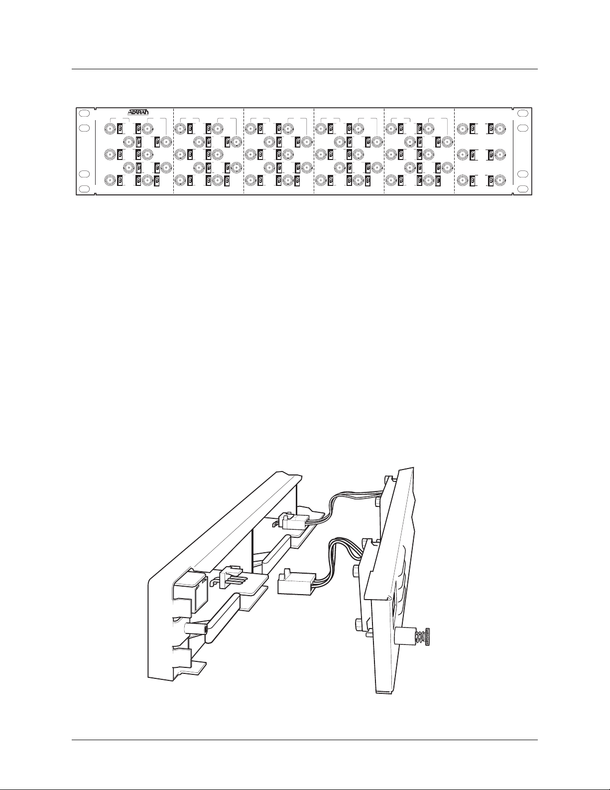
E1 Patch Panel (P/N 1200291L5)
The optional E1 patch panel connects to the MX2800 and provides 28 pairs of BNC connectors for E1
deployment (21 of which are used for E1 deployment). See Figure 1-1 on page 1-4.
61200290L1-1G 1-3
Page 22
Section 1, Product Overview MX2800 M13 Multiplexer User Manual
ON ON
ON ON
ON
TX RX
OPEN
CH 26
ON ON
EARTH
OPEN
CH 27
ON ON
EARTH
OPEN
CH 28
ON ON
EARTH
TX RX
OPEN
CH 1
ON ON
EARTH
OPEN
CH 2
EARTH
OPEN
CH 3
ON ON
EARTH
OPEN
CH 4
EARTH
OPEN
CH 5
ON ON
EARTH
ON ON
ON ON
ON
TX RX
OPEN
CH 6
ON ON
EARTH
OPEN
CH 7
EARTH
OPEN
CH 8
ON ON
EARTH
OPEN
CH 9
EARTH
OPEN
CH 10
ON ON
EARTH
ON ON
ON ON
ON
TX RX
OPEN
CH 11
ON ON
EARTH
OPEN
CH 12
EARTH
OPEN
CH 13
ON ON
EARTH
OPEN
CH 14
EARTH
OPEN
CH 15
ON ON
EARTH
ON ON
ON ON
ON
TX RX
OPEN
CH 16
ON ON
EARTH
OPEN
CH 17
EARTH
OPEN
CH 18
ON ON
EARTH
OPEN
CH 19
EARTH
OPEN
CH 20
ON ON
EARTH
ON ON
ON ON
ON
TX RX
OPEN
CH 21
ON ON
EARTH
OPEN
CH 22
EARTH
OPEN
CH 23
ON ON
EARTH
OPEN
CH 24
EARTH
OPEN
CH 25
ON ON
EARTH
Figure 1-1. E1 Patch Panel
Shipment includes two six-foot, 64-pin to 64-pin amphenol cables for direct cabling to the MX2800. Refer
to Connecting the E1 Patch Panel on page 2-5 or more information.
Battery Backup (P/N 4175043L2)
The battery backup system provides power backup in the event of power loss. This system includes the
battery, an AC battery charger, and an alarm cable.
Fan Faceplate (P/N 1200466L1)
The MX2800 fan faceplate provides the means for additional heat dissipation, allowing multiple units to be
stacked directly over each other. The fan faceplate replaces the original faceplate. It is used with the
1202289L1, 1202289L2, and 1202289L3 power supplies. Figure 1-2 shows how the fan faceplate is
installed on the chassis.
Figure 1-2. Installing Fan Faceplate
1-4 61200290L1-1G
Page 23

SECTION 2, INSTALLATION AND OPERATION
Section 2
Installation and Operation
1. INTRODUCTION
The first three tasks for installing and operating the MX2800 are to unpack, inspect, and power up. The
next three subsections detail the tasks. Additional subsections provide information for mounting the
MX2800 into an equipment rack, making the proper connection to the back panel, identifying the front
panel indicators and modular jack, and outlining the addition or removal of a card.
2. RECEIVING INSPECTION
Carefully inspect the MX2800 for any damage that might have occurred in shipment. If damage is
suspected, file a claim immediately with the carrier, keep the original packaging for damage verification
and/or returning the unit, and contact ADTRAN Customer Service. For warranty information, refer to
Appendix F, Warranty.
3. ADTRAN SHIPPING CONTENTS
After unpacking the MX2800 unit but before an initial power up, be sure that the following items are
present:
• MX2800 unit
• DC or AC power supply (Two power supplies come with the Redundant versions.)
• Controller card (Two cards come with the Redundant versions.)
• 8-pin to 6-pin modular cable (modem version only)
• 8-pin to 8-pin modular cable
• 8-pin modular to DB-9 female connector
• Two 4-position terminal lug connectors
• 3-position terminal lug connector
• Six-foot AC power cable (AC version only)
• Mounting ears and screws for 19-inch or 23-inch rack installation
• User manual or CD containing the User Manual
61200290L1-1G 2-1
Page 24

Section 2, Installation and Operation MX2800 M13 Multiplexer User Manual
NOTE
MIB files are available from ADTRAN in the support section of the
ADTRAN Web page at www.adtran.com.
4. POWER UP
The AC version of the MX2800 is provided with a 6-foot power cable terminated in a three-prong plug
which is connected to a grounded 120 VAC power receptacle.
NOTE
Power to the AC version of the MX2800 must be provided from a
grounded 120 VAC power receptacle.
The DC version of the MX2800 is provided with two 4-position modular terminal lug connectors. These
connectors simplify the initial wiring and connection or disconnection of the DC power when replacing
rackmount units.
NOTE
A 3-amp fuse is recommended for use in the fuse and alarm panel that
feeds the MX2800.
For more detailed information on power connections, refer to Section 8, Power Loss Recovery.
Once the modular connector is wired, push it firmly into one of the rear panel power connectors. Figure
2-1 on page 2-3 and Ta bl e 2 -1 on page 2-3 illustrate the DC power connector and give definitions for the
four connector symbols.
NOTE
The chassis should be connected to an earth ground using the ground stud
located between the AC and DC power sources on the rear panel.
2-2 61200290L1-1G
Page 25
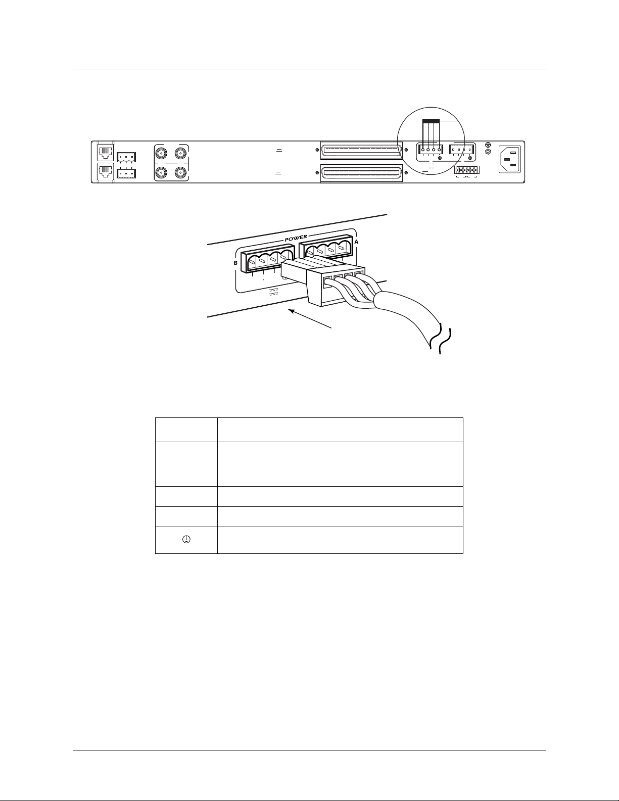
MX2800 M13 Multiplexer User Manual Installation and Operation, Section 2
115 AC 50/60Hz
0.8A
USE COPPER
CONDUCTORS ONLY!
S
B
PWR
–
+
FAIL
-48V 0.7A
+24V 1.5A
DC POWER
PWR
FAIL
–
+
AB
TRSTR
CLKACLK
L
NONCRITICAL
A
N
M
NO COM NC
O
D
E
M
CRITICAL
DS3/STS-1
OUT IN
A
B
PWR
FAIL
-48V 0.7A
+24V 1.5A
DSX-1/E1
(OUT)
DSX-1/E1
(IN)
+
Figure 2-1. DC Power Connector
Table 2-1. DC Connector Symbol Definitions
Symbol Definition
PWR FAIL
Battery backup connector. If the AC fails, a trap is sent to
alert user when connected to the 4175043L2 battery
backup or equivalent system.
–
RET
Negative side of DC power source (usually –48 VDC)
Positive side of DC power source (usually ground)
Frame Ground
The following UL requirements must be met during installation of the MX2800 DC version:
1. Disconnect all power sources prior to servicing. Unit may use multiple power sources.
2. Input: Minimum 48 VDC, 0.8 amps
3. Input: Minimum 120 VAC, 0.32 amps
4. Connect to a reliably grounded –48 VDC source which is electrically isolated from the AC source. Use
24 VDC source for 1202289L3.
5. The branch circuit overcurrent protection must be a fuse or circuit breaker rated minimum 48 VDC,
maximum 20 amps.
61200290L1-1G 2-3
Page 26

Section 2, Installation and Operation MX2800 M13 Multiplexer User Manual
6. A readily accessible disconnect device that is suitably approved and rated must be incorporated in the
field wiring.
7. The chassis should be connected to an earth ground using the ground stud located between the AC and
DC power sources on the rear panel.
8. The unit must be installed in accordance with the requirements of NEC NFPA 70.
9. The unit must be installed in accordance with Articles 400 and 364.8 of the National Electrical Code
NFPA 70 when installed outside of a Restricted Access Location (i.e., Central Office, behind a locked
door, service personnel area only).
10. Care should be taken not to upset the stability of the equipment rack after installation is complete.
CAUTION
Use copper conductors only for DC power and ground connection.
5. RACKMOUNT INSTALLATION
The MX2800 can be mounted into a standard 19-inch or 23-inch equipment rack. Follow these steps to
mount the unit into a rack:
1. Install the mounting flanges on each side of the MX2800 at one of the three available positions.
CAUTION
Be sure to install the flanges with the screws provided.
2. After the flanges have been installed, position the MX2800 at the correct location within the rack and
secure the mounting flanges to the mounting rails of the rack.
3. Make all network, DTE, and power connections to the rear of the unit. Refer to Power Up on page 2-2
for more information on making the DC power connection.
4. Using the 8-position modular to DB-9 female connector and the 8-pin to 8-pin modular cable, connect
a VT100 terminal device to the
CRAFT port on the front panel of the unit.
NOTE
Two MX2800s can be stacked with out any spacing between the units.
ADTRAN recommends 1U (1.75”) of separation above and below the
two stacked units. This spacing allows the units to dissipate heat. The
design of the MX2800 uses the chassis to distribute heat generated by the
unit’s internal cards. This design allows the units to operate without a
cooling fan, thus increasing overall reliability of the units.
2-4 61200290L1-1G
Page 27
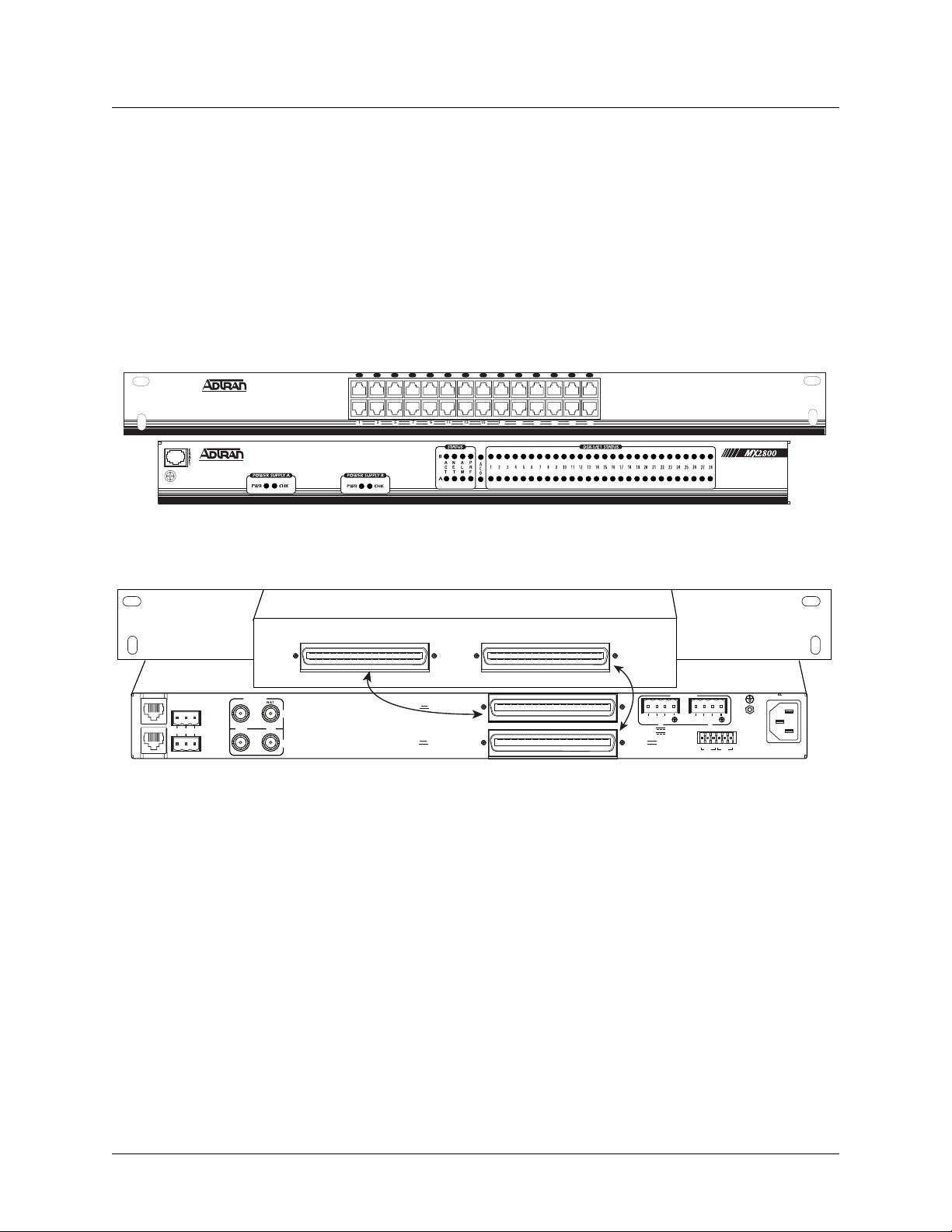
MX2800 M13 Multiplexer User Manual Installation and Operation, Section 2
Connecting the Breakout Panel
The optional breakout panel (P/N 1200291L1) connects to the MX2800 via the IN and OUT amphenol
connectors located on the back of the unit and provides 28 RJ connectors for the individual T1s/E1s.
Shipment includes two six-foot, 64-pin to 64-pin amphenol cables for direct cabling to the MX2800.
Connect the breakout panel’s
breakout panel’s
OUT amphenol connector to the MX2800’s OUT amphenol connector. See Figure 2-2.
IN amphenol connector to the MX2800’s IN amphenol connector and the
FRONT VIEW
2 4 6 8 10 12 14 16 18 20 22 24 26 28
1 3 5 7 9 11 13 15 17 19 21 23 25 27
N
A
P
A
E
L
R
C
T
M
F
T
REAR VIEW
INOUT
Cable 2
PWR
–
+
FAIL
-48V 0.7A
+24V 1.5A
DC POWER
PWR
FAIL
–
+
AB
TRSTR
CLKACLK
B
DS3/STS-1
OUT IN
NET
A
B
Cable 1
L
NONCRITICAL
A
N
M
NO COM NC
O
D
E
M
CRITICAL
DSX-1/E1
(OUT)
DSX-1/E1
(IN)
Figure 2-2. The Breakout Panel
Connecting the E1 Patch Panel
The optional E1 patch panel (P/N 1200291L5) connects to the MX2800 via the TX and RX amphenol
connectors located on the back of the unit and provides 28 pairs of BNC connectors for the individual
T1/E1s. Shipment includes two 6-foot, 64-pin to 64-pin amphenol cables for direct cabling to the MX2800.
Connect the E1 patch panel’s
patch panel’s
RX amphenol connector to the MX2800's OUT amphenol connector.
TX amphenol connector to the MX2800’s IN amphenol connector and the E1
S
USE COPPER
CONDUCTORS ONLY!
115 AC 50/60Hz
0.8A
61200290L1-1G 2-5
Page 28
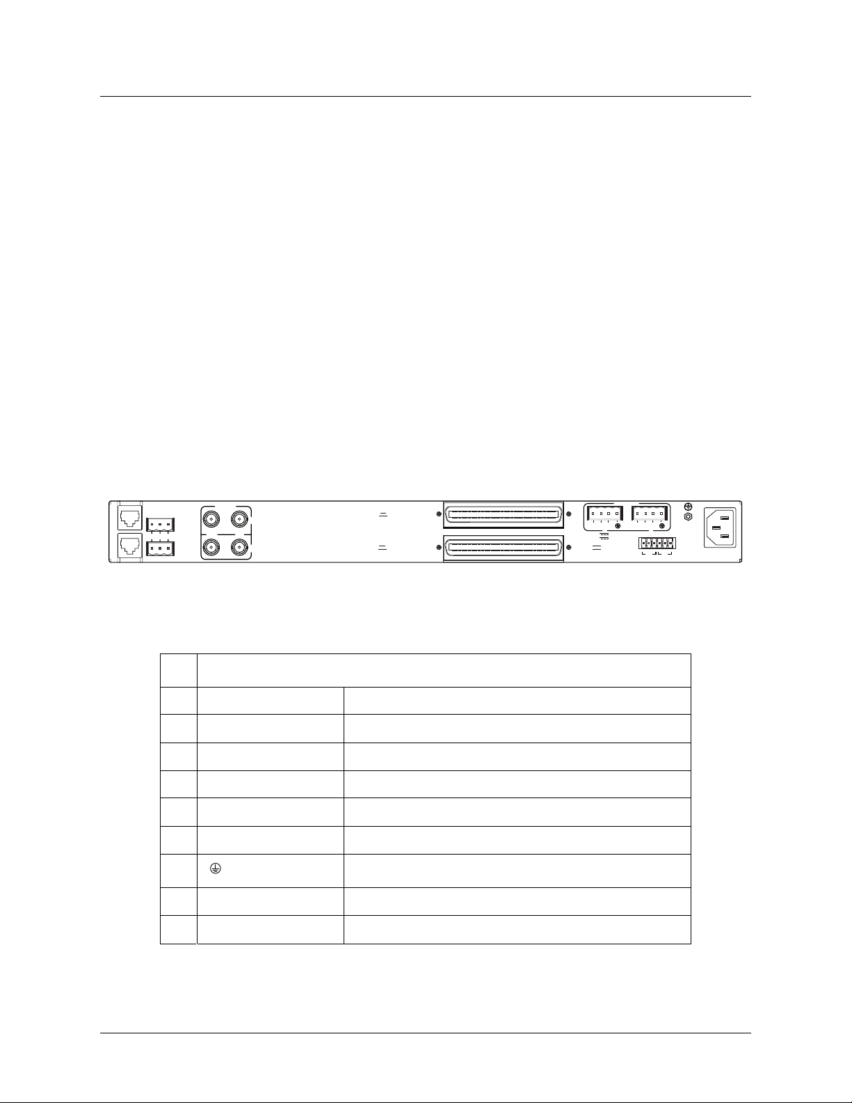
Section 2, Installation and Operation MX2800 M13 Multiplexer User Manual
6. REAR PANEL
The MX2800 rear panel is equipped as follows:
• Ethernet local area network (LAN) port
•Modem port
• Two alarm output terminal blocks
• Two sets of DS-3 in/out jacks
• Two amphenol connectors
• DC/AC power connection
• Ground stud
• Three-prong AC connection
• Wire-wrap pins for external connection of BITS clock (STS-1)
Descriptions for the items shown in Figure 2-3 are explained in Tab le 2- 2. Pin assignments are given in
the tables in Appendix B, Pinouts.
S
USE COPPER
CONDUCTORS ONLY!
9
7
8
115 AC 50/60Hz
0.8A
PWR
–
+
FAIL
B
-48V 0.7A
+24V 1.5A
DC POWER
6
PWR
FAIL
–
+
A
TRSTR
CLKACLK
B
L
NONCRITICAL
A
N
1
M
NO COM NC
O
D
E
2
M
CRITICAL
DS3/STS-1
3
OUT IN
A
4
B
DSX-1/E1
(OUT)
DSX-1/E1
(IN)
5
Figure 2-3. MX2800 Rear View
Table 2-2. MX2800 Review View Identifiers
#Item Function
1 Ethernet LAN 10Base-T Ethernet connection
2 Modem Telephone line connection for internal V.34
3 Noncritical/Critical Connections for external audible/visual alarms
4 DS3/STS-1 T3 service connection for controller cards A and B
5 DSX-1/E1 64-pin female amphenol connectors for T1/E1s
6 Power DC power connection
7 Ground stud
8 115 VAC 50/60 Hz AC power connection
9 BITS Clock Wire-wrap pins for external connection of BITS clocks
2-6 61200290L1-1G
Page 29

MX2800 M13 Multiplexer User Manual Installation and Operation, Section 2
LAN Port
The LAN port is an 8-pin modular connector that provides a 10Base-T Ethernet LAN interface. This LAN
interface is used for SNMP and Telnet control.
NOTE
Connect the LAN port to intra-building wiring only.
Modem Port
The modem port is an 8-pin modular jack that provides a telephone line (POTS) connection for the internal
V.34 modem.
NOTE
Information regarding the built-in modem applies to the part numbers
4202290L1, 4202290L2, 4202290L3, and 4202290L4.
The MX2800 can be configured as a dial-in host and also as a dial-out-on-trap device (the unit dials out to
a specified host to report error conditions).
Noncritical and Critical Alarm Connectors
The alarm connectors connect to the three contacts of a Form C type relay on the main board of the
MX2800. This relay is activated any time the MX2800 detects an alarm condition on the T3 network
interface. Both
Connect alarms to one of the three-position modular terminal lug connectors. These connectors simplify
the initial wiring and connection or disconnection of the alarms when replacing rackmount units. Once a
modular connector is wired, push it firmly into the rear panel
The alarm functions can be enabled or disabled through the Alarm Relays section of the Configuration
menu. For more information, refer to Alarm Relay Configuration on page 3-33.
NC (normally closed) and NO (normally open) contacts are provided.
NONCRITICAL or CRITICAL connector.
DSX-3 Interfaces
The DSX-3 network interfaces are full-duplex circuits provided by four BNC coaxial cable connections
(two for each controller card). The receive data from the network is connected to the Rx (
while the transmit data from the MX2800 is connected to the Tx (
Circuit and Network Redundancy for more specific information about connecting the DS3 interface in
redundant and nonredundant systems.
OUT) connectors. Refer to Section 7,
IN) connectors,
61200290L1-1G 2-7
Page 30
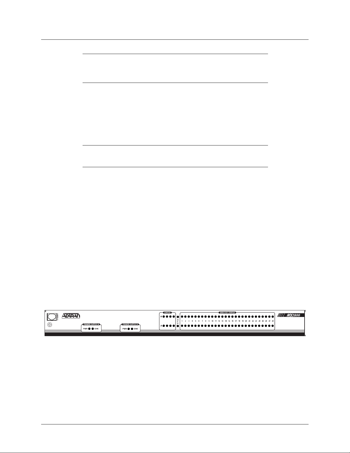
Section 2, Installation and Operation MX2800 M13 Multiplexer User Manual
NOTE
DSX-3 interfaces must be connected using coaxial cables that have the
shields grounded at both ends.
DSX-1/E1 Interfaces
The DSX-1/E1 interfaces are 64-pin amphenol connectors. These interfaces provide Tx and Rx
connections between the unit and equipment such as wire-wrap patch panels, punch-down panels, or
breakout panels.
NOTE
Connect the DSX-1/E1 interfaces to intra-building wiring only.
Power Connection
The DC power connections are described in Power Up on page 2-2.
7. FRONT PANEL
The MX2800 front panel is shown in Figure 2-4. Descriptions of each part of the front panel follow:
• Craft Port on page 2-8
• ACO Buttons on page 2-15
• Power Supply A/B Status LEDs on page 2-15
• Controller Cards Status LEDs on page 2-15
• T1/E1 Status LEDs on page 2-17
A
N
A
P
C
E
L
R
T
T
M
F
Figure 2-4. MX2800 Front Panel
Craft Port
The craft port, an 8-pin modular jack, provides connection to a VT100 EIA-232 compatible interface
(using the supplied 8-pin modular to DB-9 female connector and the 8-pin to 8-pin modular cable).
2-8 61200290L1-1G
Page 31

MX2800 M13 Multiplexer User Manual Installation and Operation, Section 2
Establishing Terminal Connection
NOTE
A Telnet menu session has priority over a terminal menu session through
the craft port. If a terminal menu session is active when a
session is initiated, the terminal menu session will be disabled while the
Te ln e t menu session is active.
To connect the MX2800 to a VT100 terminal, follow this procedure:
1. Configure the VT100 terminal for 9600, 19200, 38400, or 57600 baud, 8-bit characters, no parity, and
one stop bit (xxxx, 8N1).
2. Using the ADTRAN-provided terminal interface cable adapter, connect the DTE port of a terminal to
the 8-pin modular jack labeled
CRAFT on the MX2800 front panel.
3. Initialize the terminal session.
Tel ne t menu
4. Press
ENTER repeatedly until the username prompt appears.
5. Enter the username. The factory default username is adtran. The password prompt appears.
6. Enter the password. The factory default password is adtran. The Main Menu appears. See Figure
2-5 on page 2-10.
Main Menu
Make selections on the Main Menu by entering the number corresponding to the chosen parameter or the
desired key strokes. Refer to Navigating Within the Menus on page 2-10
NOTE
A new Telnet session may take priority over an existing one if a username
and password are provided that have ADMIN privileges
61200290L1-1G 2-9
Page 32

Section 2, Installation and Operation MX2800 M13 Multiplexer User Manual
Figure 2-5. Main Menu
NOTE
The letter displayed in the upper left-hand corner of the terminal menu
indicates which controller card is active (A or B).
Navigating Within the Menus
Navigate within the MX2800 terminal menus using the following procedures:
To... Press...
select an item the number corresponding to your choice,
scroll left and right
within the same screen
return to the previous
menu
and then press the
the left and right arrow keys. Additional
screens are available when < or > is displayed in the top portion of the menu
the
ESC key
ENTER key
end the terminal session
refresh the display
2-10 61200290L1-1G
CTRL+C
CTRL+R
Page 33

MX2800 M13 Multiplexer User Manual Installation and Operation, Section 2
To... Press...
scroll up and down
within the same screen
the up and down arrow keys. Additional
screens are available when ∧ or ∨ is displayed in the top portion of the menu.
The MX2800 Main Menu consists of the following sections:
Status
Provides information on the current state of the DS3, power supplies, system, DS2s, and T1/E1 lines. See
Figure 2-6 for an illustration. Refer to Section 4, Status for more detailed information.
Figure 2-6. Status Menu
Statistics
Provides detailed statistical information (both current and historical) for the DS3, DS2s, and T1/E1 lines.
See Figure 2-7 on page 2-12 for the Statistics
menu. Refer to Statistics on page 5-1 for more detailed
information.
61200290L1-1G 2-11
Page 34

Section 2, Installation and Operation MX2800 M13 Multiplexer User Manual
Figure 2-7. Statistics Menu
Configuration
Sets DS3 network, T1/E1, and system management parameters. See Figure 2-8. Refer to Section 3,
Configuration for more detailed information.
Figure 2-8. Configuration Menu
2-12 61200290L1-1G
Page 35

MX2800 M13 Multiplexer User Manual Installation and Operation, Section 2
Loopbacks
Performs loopback tests over the DS3, DS2s, or T1/E1 lines. See Figure 2-9 for an illustration of the
Loopback Menu. Refer to Section 6, Loopbacks for more detailed information.
Figure 2-9. Loopback Menu
Telnet Client
A Telnet session may be established with any device visible in the network from the MX2800. See Figure
2-10 on page 2-14 for an illustration of the Telnet Client menu.
61200290L1-1G 2-13
Page 36

Section 2, Installation and Operation MX2800 M13 Multiplexer User Manual
Figure 2-10. Telnet Client Menu
From the Telnet Client menu, specify the destination IP address and the desired TCP port number. Attempt
to establish the TCP connection.
Once the connection is established, the new session becomes visible in the menu and all user inputs are
forwarded to the destination address. When the session with the destination device is terminated, the
MX2800 menu returns to the Telnet Client menu and all user input are processed locally by the MX2800.
NOTE
An attempted or established connection can be terminated by using the
escape sequence. This escape sequence is displayed for reference at the
bottom of the Telnet Client menu and consists of the control key plus the
right bracket key (CTRL+]).
A connection can be established with the Telnet Client regardless of how the MX2800 (via craft, LAN
port, modem port, or IP forwarding over the DS3 PMDL link) is accessed. The MX2800 supports only one
menu session at a time.
CAUTION
The MX2800 does not reliably support binary file transfers (XModem,
YModem, etc.) over the built-in Telnet Client because of compatibility
issues involving the handling of certain control characters by some
terminal applications and binary file transfer protocols.
2-14 61200290L1-1G
Page 37

MX2800 M13 Multiplexer User Manual Installation and Operation, Section 2
Logout
The Logout selection ends the terminal session and logs out of the system. A valid username and password
are required before a new session can begin. The unit will also log out of a terminal session automatically
if the session remains inactive for a certain period of time. For more information, see the section Terminal
Time Out on page 3-33.
Privilege Level
The privilege level of the currently active terminal session is displayed in this field.
ACO Buttons
The ACO (alarm cut off) buttons turn off an active audible alarm. Since the buttons are recessed, use a pen
or other pointed instrument to press them. Once an
disabled until the condition has cleared.
ACO button deactivates an alarm, the alarm remains
Alarms can also be turned off remotely by using a selection found in the
information, refer to Acknowledge Alarms (ACO) on page 4-6.
Status menu. For more
LED Descriptions
The MX2800 has LED status indicators for the power supplies, the DS3 state, the controller cards, and the
individual T1s/E1s. These LEDs are identified below:
Power Supply A/B Status LEDs
The PWR LED is active when the unit is on and receiving full power. The CHK LED is active when the
power supply is failing or is providing low power and needs to be checked.
Controller Cards Status LEDs
The STATUS LEDs apply to the two controller cards. The LEDs provided are ACT (active), DS3, ALM
(alarm), and
whether it blinks, alternates color, or is on solid). The condition descriptions vary depending on whether
the LED represents the active controller card or the controller card on standby. The following tables
provide LED definitions for the active cards (see Tab le 2 -3 on page 2-16) and T1/E1 cards (see Tab le 2 -4
on page 2-17).
PRF (performance). Various conditions are indicated by the state of the LED (its color and
61200290L1-1G 2-15
Page 38

Section 2, Installation and Operation MX2800 M13 Multiplexer User Manual
Table 2-3. LED Conditions for Active Cards
LED LED State Card Condition
ACT
NET
ALM
Green solid Normal (all OK)
Green/amber alternating Normal + console open
Red solid Self test failed
Amber solid Software update in progress
Red/amber alternating Self test failed + console open
Red blinking Card failure
Green solid Normal (all OK)
Red blinking LOS
Red solid AIS, LOF, RAI, idle alarms
Amber solid In test (Local)
Amber flashing In test (Remote)
Red/amber alternating In test with alarms
Green solid Normal (no alarm)
Red blinking Critical alarm
Red solid Non-critical alarm
Amber blinking Critical alarm suppressed (ACO button was pushed)
PRF
Amber solid Non-critical alarm suppressed (ACO button was pushed)
Green solid Normal (all OK)
Red flash (once per event) Single/burst CV
Red blinking Continuous code violations
Red solid XCV threshold exceeded (refer to XCV Threshold on page 3-15)
NOTE
The PRF (performance) LED refers to the DS3 only
2-16 61200290L1-1G
Page 39

MX2800 M13 Multiplexer User Manual Installation and Operation, Section 2
Table 2-4. LED Conditions for Standby Cards
LED LED State Card Condition
ACT Green blinking Normal (all OK)
Amber solid Software update in progress
Red blinking Self test failed
NET Off Normal (all OK)
Red blinking DS3 failure
ALM Off Normal (no alarm)
PRF Off Normal (all OK)
T1/E1 Status LEDs
These LEDs apply to each individual T1 or E1. Various conditions are indicated by the state of the LED
(its color and whether it blinks, alternates color, or is on solid). The condition descriptions vary depending
on whether the LEDs represent T1s or E1s of the active controller card or the controller card on standby.
Tab le 2 -5 provides LED definitions for the active and standby cards.
Table 2-5. T1/E1 LED Conditions
LED LED State T1/E1 Condition
Active
Card
Green solid Normal (all OK)
Off Disabled
Red blinking LOS
Red flash (once per event) Single/burst CV
Red solid XCV threshold exceeded or AIS (refer to XCV Threshold on
page 3-15)
Amber solid In test (Local)
Green/amber alternating In test (Remote)
Red/amber alternating In test with alarms
Standby
Card
Off Normal (all OK)
or
N/A (in the case of E1 configuration)
Red blinking T1/E1 failure
61200290L1-1G 2-17
Page 40

Section 2, Installation and Operation MX2800 M13 Multiplexer User Manual
8. REPLACING OR INSTALLING CARDS
The MX2800 is designed with hot-swappable controller cards and power supplies. To replace or install a
controller card or power supply, remove the front cover of the MX2800 with a phillips head screwdriver.
Once the front of the MX2800 has been removed, the power supply and controller card slots will be
visible. The two power supplies are located at the left of the chassis, and the controller cards are stacked on
the right side of the chassis. To remove a card, use the locking lever(s) to pull the backplane connector
away from the backplane. Once the backplane connector has been disconnected, carefully pull the card
straight out of the chassis. To replace or install a card, line up the card with the guide grooves and carefully
insert the card into the chassis until the backplane connector reaches the backplane. Finally, use the locking
levers to seat the card all the way into the slot of the chassis. Once all cards have been replaced or installed,
replace the front cover of the MX2800. Figure 2-11 shows how to remove and replace the front cover.
Figure 2-11. Replacing or Installing Cards
2-18 61200290L1-1G
Page 41

SECTION 3, CONFIGURATION
Section 3
Configuration
1. INTRODUCTION
To configure the MX2800, use a 10Base-T Ethernet connection, a SLIP/PPP modem port, or a VT100
terminal. Figure 3-1 shows the Configuration menu.
NOTE
A Telnet menu session has priority over a terminal menu session through
the craft port. If a terminal menu session is active when a Telnet menu
session is initiated, the terminal menu session will be disabled until the
Telnet session is closed.
Figure 3-1. Configuration Menu
Detailed descriptions of the menu selections are given in the following subsections. The Configuration
menu provides the following five submenus:
• Network Interface on page 3-4
61200290L1-1G 3-1
Page 42

Section 3, Configuration MX2800 M13 Multiplexer User Manual
• T1/E1 Interface on page 3-8
• System Management on page 3-16
• Utilities on page 3-38
• Save Configuration and Alarm Log on page 3-44
Figure 3-2 on page 3-3 shows the
Configuration menu tree.
3-2 61200290L1-1G
Page 43

MX2800 M13 Multiplexer User Manual Configuration, Section 3
Network Interface
T1/E1 Interface
System Management
Utilities
DS3 Configuration
Protection Configuration
Miscellaneous
DS2 Configuration
Auto Enable Delay
State
Line Coding
Line Length
Loopback Detection
Circuit Protection
Line Identification
XCV Threshold
Mgmt Options
SNMP Mgmt Options
Network Date/ Time Options
System Security
Date & Time
Miscellaneous
Load Default Settings
Update FLASH Software
Configuration Transfer
System Reset
DS2 1-7
T1 # 1-28
T1 # 1-28
T1 # 1-28
T1 # 1-28
Disabled*
IE-3
IE-4
IE-5
IE-6
Local IP Address
Gateway IP Address
Subnet Mask
Modem Rmt IP Addr (List 1)
Management Port
Forward IP to Remote DS3
DS3 Remote IP Address
DS3 IP MTU
Dialup Options (List 1)
User Account Management
Terminal Timeout
Date
Time
IP Security
IP Hosts
Load Default settings OTHER THAN system management
Load SYSTEM MANAGEMENT default settings
Load ALL default settings
Update via XMODEM
Update via TFTP Server
T1 # 1-28
T1 # 1-28
Framing
Timing
Remote Loopbacks
XCV Threshold
Active Controller
Network Protection
Max Switch Threshold (3)*
Min Switch Period (10)*
Disabled
Enabled*
SNMP State
Trap IP Address
Trap Generation
Read Community Name
Write Community Name
Trap Community Name
System Name
State
Server IP Address
Refresh Period
DST Automatic Adjustment
Local Time Zone
C-BIT*
M13
Loopback Time Out
Shutdown Standby
Disabled
Enabled
Auto Enable*
Disabled*
CSU
NIU
Radius Mgmt options
Local User Accounts
Loop*
Local
AMI
B8ZS*
0-133 ft.*
133-266 ft.
266-399 ft.
399-533 ft.
533-655 ft.
Disabled
FEAC/C-BIT*
FEAC
C-BIT
A
B
Disabled*
Enabled
Controller Traps
Power Supply Alarm Traps
DS3 Alarm Traps
DS2 Alarm Traps
T1/E1 Alarm Traps
MIB II Standard Alarm Traps
Radius State
Server IP Address
UDP Port
Privilege Level
Shared Secret Visibility
Shared Secret
Response Timeout
Maximum Retries
Alarm Relay Configuration
Equipment Identification
Syslog Setup
Auto Save
Craft baud rate
Disabled*
IE-3
IE-4
IE-5
IE-6
Disabled
1 min.
5 min.*
10 min.
15 min.
30 min.
45 min.
1 hour
Save Configuration & Alarm Log
* = default settings
Figure 3-2. Configuration Menu Tree
61200290L1-1G 3-3
Page 44

Section 3, Configuration MX2800 M13 Multiplexer User Manual
2. NETWORK INTERFACE
Select Network Interface to access the network configuration parameters. See Figure 3-3. Configure the
MX2800 network settings to match the DS3 signal received from the service provider.
Figure 3-3. Network Configuration Menu
DS3 Configuration
The DS3 Configuration selections are used to configure the DS3 network settings to match the desired
application. Descriptions of these settings are explained below.
Framing
The framing format is used to match the format of the receive signal at the network interface. The MX2800
supports C-bit and M13 framing formats.
NOTE
M13 may not be selected when IP Forwarding is active.
Line Length
The line length is set to reflect the physical length of the DS3 network line.
• Long should be used if the cabling distance exceeds 225 feet.
• Short should be used if the distance is less than 225 feet.
3-4 61200290L1-1G
Page 45

MX2800 M13 Multiplexer User Manual Configuration, Section 3
NOTE
First and second generation DS3 controller cards (P/N 1200288Lx and P/
N 1202288Lx) use Long for distances over 50 feet and Short for distances
under 50 feet.
NOTE
Fifth generation DS3 controller cards (P/N 1205288Lx) do not require a
DS3 line length setting; therefore, Line Length does not appear as a menu
item.
Timing
When the MX2800 is connected to a network that provides timing, configure the MX2800 for LOOP
timing to derive timing from the network. If the MX2800 is the master timing source for the circuit,
configure the MX2800 to LOCAL. In applications where two MX2800s are connected back-to-back with
an un-channelized DS3, configure one MX2800 to LOOP and one MX2800 to LOCAL
.
Remote Loopbacks
The following four options are available for remote loopbacks:
• FEAC/C-BIT
the DS3 Far End Alarm and Control (FEAC) channel and/or DS2-level C bits. This mode is valid in
C-BIT and M13 framing formats.
both
• FEAC is used to allow the MX2800 to respond only to remote loopback requests received over the DS3
FEAC channel. This mode is valid only when using C-BIT framing. In this mode, DS2 C-bit loopbacks
will be ignored.
• C-BIT is used to allow the MX2800 to respond only to remote loopback requests received over DS2 C
bits. This mode is available when operating in either C-BIT or M13 framing. In this mode, FEAC
loopbacks received when operating in C-BIT framing will be ignored.
• Disabled is used to ignore all out-of-band loopback requests (FEAC and DS2 C-BIT). When
is selected, the MX2800 will still respond to individual T1 in-band CSU/NIU loopbacks if so configured
in the T1/E1 Loopback Detection menu.
is used t o allow the MX2800 to respond to remote loopback requests received over either
Disabled
NOTE
Choose FEAC/C-BIT via menus in either C-BIT or M13 framing modes;
however, there is no FEAC channel when framing is set to M13.
Therefore, no DS3 far end alarms or loopback requests via the FEAC will
be valid when the MX2800 is configured for M13.
61200290L1-1G 3-5
Page 46

Section 3, Configuration MX2800 M13 Multiplexer User Manual
XCV Threshold
Excessive code violations (XVC) Threshold sets a limit on CVs accepted by the unit before it switches
controller cards. If set to Disabled, code violations will not cause the unit to switch controller cards. The
threshold limits are described in Tabl e 3- 1.
Table 3-1. XCV Threshold Limits
Setting The unit switches controller cards if...
1E
1E
1E
1E
-3
-4
-5
-6
More than one out of every 1,000 bits received on the DS3 contains a code violation
More than one out of every 10,000 bits received on the DS3 contains a code violation
More than one out of every 100,000 bits received on the DS3 contains a code violation
More than one out of every 1,000,000 bits received on the DS3 contains a code violation
Protection Configuration
The MX2800 houses two controller cards for 1:1 protection against hardware failure. The two cards can
also provide network protection, supporting two T3 circuits simultaneously. The selections in this menu
allow customizing the unit’s protection setup.
Active Controller
This field displays A or B, indicating the active controller card. This setting can be used to force the
controller cards to switch. For example, if controller card A is active and B is selected, a switch-over
occurs immediately.
Network Protection
This field enables or disables the unit’s ability to automatically route information to the backup T3 in the
event of a primary T3 failure. If enabled, all information is automatically routed to the backup T3. If
disabled, the stand-by controller protects against failures of the active controller.
Maximum Switch Threshold
The value entered in this field determines the number of times per hour the unit is allowed to switch
between controller cards. If, in an hour, the cards switch more than the Maximum Number of Switches, the
unit issues a trap and stops switching cards for the next 24 hours. Refer to Trap Descriptions on page 3-22.
The default setting is three times an hour. This count may be cleared by clearing
Protection Switch alarm
counts. See Figure 5-13 on page 5-14.
Min. Switching Period
After the unit switches controller cards, the number of seconds entered in this field must pass before
another card switch will be allowed. The default setting is 10 seconds.
3-6 61200290L1-1G
Page 47

MX2800 M13 Multiplexer User Manual Configuration, Section 3
Miscellaneous
The Miscellaneous menu selections are used to configure the Loopback Timeout and Shutdown Stand-by
settings. Descriptions of these settings are explained below.
Loopback Timeout
The Loopback Timeout option is used to set the loopback timeout to one of the following:
• Disabled
•1 min.
•5 min.
• 10 min.
• 15 min.
• 30 min.
• 45 min.
•1 hr.
• 120 min.
Shutdown Stand-By
The Shutdown Stand-by option causes the system to disable the standby controller card, thus making it
unavailable for protection switches. Once this option has been selected and the standby controller has been
shut down, the option changes to Reset Stand-by. Selecting this option resets and reactivates the standby
controller, thus making it available for protection switching.
DS2 Configuration
The MX2800 can individually frame each of the seven DS2 streams in M12 (four T1s) or G.747 (three
E1s) format. When set to M12 (4xT1), the four T1s for the selected group are framed per ANSI T1.107.
When set to G.747 (3xE1), the first three T1/E1 ports of the selected group are framed per CCITT G.747
into the DS3 stream. The fourth T1/E1 port of the selected group is not available in this mode. Any combination of M12 (4xT1) and G.747 (3xE1) is allowed.
61200290L1-1G 3-7
Page 48

Section 3, Configuration MX2800 M13 Multiplexer User Manual
3. T1/E1 INTERFACE
The T1/E1 Interface menu, see Figure 3-4, is used to activate/deactivate individual T1s and E1s and to set
their line coding, length, loopback detection, circuit protection, and line ID string. The T1/E1 code violation threshold is also configured through this menu. Configuration selections are described in the following
sections.
NOTE
A DS2 can be divided into either three E1s or four T1s. Therefore, when
dealing with an E1 configuration, some of the fields in the T1/E1
Interface menus do not apply (and therefore display N/A).
Figure 3-4. T1/E1 Interface Menu
3-8 61200290L1-1G
Page 49

MX2800 M13 Multiplexer User Manual Configuration, Section 3
T1/E1 State
The T1/E1 lines are set to Disabled, Enabled, or Auto Enable. In Auto Enable, the port is not fully enabled
(and alarms are not issued) until a T1/E1 signal is detected on that port’s receiver for a specified period of
time. See Figure 3-5 on page 3-9. This period of time is set by the Auto Enable Delay option. The options
are as follows:
• 2 seconds (default)
• 1 hour
• 2 hours
• 12 hours
•1 day
•2 days
•7 days
Figure 3-5. T1/E1 State Menu
Set Multiple
The Set Multiple, see Figure 3-6 on page 3-10, option is used to enable or disable a contiguous group or all
of the T1/E1s at one time. To enable or disable all T1/E1s, set
before leaving the menu. To enable or disable only some of the T1/E1s, set
the desired lines. Enter
Apply settings. Either leave the menu at this point or continue to enter new First and
Last numbers for other lines.
61200290L1-1G 3-9
First to 1 and Last to 28. Enter Apply settings
First and Last to correspond to
Page 50

Section 3, Configuration MX2800 M13 Multiplexer User Manual
NOTE
Settings should be applied following each change.
Figure 3-6. Set Multiple Menu
T1/E1 Line Coding
Set the line code for each individual T1/E1 interface to match the connected device. See Figure 3-7 on
page 3-11. The choices available for T1 are AMI and B8ZS. The choices available for E1 are AMI and
HDB3. Select Set Multiple to set a contiguous group or all of the T1s (or E1s) to the same value at the
same time. Refer to Set Multiple on page 3-9 for a description of the
Set Multiple option.
3-10 61200290L1-1G
Page 51

MX2800 M13 Multiplexer User Manual Configuration, Section 3
Figure 3-7. T1/E1 Line Coding Menu
T1/E1 Line Length
Set the line length for each T1 interface according to the distance from the MX2800 to the connecting DSX
termination. See Figure 3-8 on page 3-12. The E1 Line Length is not selectable and remains at 0-6 dB
loss. Select
length at the same time. Refer to Set Multiple on page 3-9 for a description of the
Set Multiple to configure the line length for a contiguous group or all of the T1s to the same
Set Multiple option.
61200290L1-1G 3-11
Page 52

Section 3, Configuration MX2800 M13 Multiplexer User Manual
Figure 3-8. T1/E1 Line Length Menu
T1/E1 Loopback Detection
The T1/E1 Loopback Detection option is used to set how the T1/E1 lines respond to loopback requests
coming from the network. See Figure 3-9 on page 3-13.
3-12 61200290L1-1G
Page 53

MX2800 M13 Multiplexer User Manual Configuration, Section 3
Figure 3-9. Loopback Detection Menu
The following options are available for detection:
• Disabled is used to cause the T1/E1 lines to ignore in-band loop-up and loop-down codes.
• CSU is used to cause the channel to loop up or loop down when it receives a CSU loop-up or loop-down
pattern for more than 5 seconds.
• NIU is used to cause the channel to loop up or loop down when it receives an NIU loop-up or loop-down
pattern for more than 5 seconds.
Select Set Multiple
to Set Multiple on page 3-9 for a description of the
to set a contiguous group or all of the T1/E1s to the same value at the same time. Refer
Set Multiple option.
T1/E1 Circuit Protection
T1/E1 Circuit Protection determines which circuit is allowed to initiate a protection switch if a failure in
the circuitry for that channel is detected. See Figure 3-10 on page 3-14. If a T1/E1 is set to
failure of the circuitry of that one channel does not cause a protection switch. If set to
of a channel causes a protection switch to occur if the Protection Threshold setting in this menu is
exceeded.
Disabled, the
Enabled, the failure
61200290L1-1G 3-13
Page 54

Section 3, Configuration MX2800 M13 Multiplexer User Manual
Figure 3-10. Circuit Protection Menu
The Protection Threshold setting determines how many of the Enabled lines must fail before a card switch
occurs. If the failure of a single protected (enabled) line is to cause a card switch, set the
old
to 1. Choices include 1 through 28.
Protection Thresh-
Select Set Multiple to set a contiguous group or all of the T1/E1s to the same value at the same time. Refer
to Set Multiple on page 3-9 for a description of the
Set Multiple selection.
T1/E1 Line Identification
This field is used to enter user-configurable text strings to name the individual T1/E1 lines. See Figure 3-
11 on page 3-15. This field will accept up to 18-alphanumeric characters, including spaces and special
characters.
3-14 61200290L1-1G
Page 55

MX2800 M13 Multiplexer User Manual Configuration, Section 3
Figure 3-11. Line Identification Menu
XCV Threshold
This value sets a limit on excessive code violations (ECVs) accepted by the unit over an individual T1/E1
line before it switches controller cards. If set to
controller cards. The threshold limits are described in Tab le 3 -2 .
Table 3-2. XCV Threshold Limits for T1/E1
Setting The unit switches controller cards if...
1E
1E
1E
1E
-3
-4
-5
-6
More than one out of every 1,000 bits received on a T1/E1 line contains a code violation
More than one out of every 10,000 bits received on a T1/E1 line contains a code violation
More than one out of every 100,000 bits received on a T1/E1 line contains a code violation
More than one out of every 1,000,000 bits received on a T1/E1 line contains a code violation
Disabled, code violations will not cause the unit to switch
61200290L1-1G 3-15
Page 56

Section 3, Configuration MX2800 M13 Multiplexer User Manual
4. SYSTEM MANAGEMENT
Configure the MX2800 for management through SNMP, Telnet, or a VT100 interface. See Figure 3-12 on
page 3-16. Embedded SNMP and Telnet are available via a SLIP/PPP modem port or 10Base-T Ethernet
interface. This menu also includes options used to customize the unit’s alarm and trap generation, security
setup, and equipment identification. The fields of the System Management Configuration menu vary
depending upon the configuration of the options in the shelf.
Figure 3-12. System Management Configuration Menu
CAUTION
Configuration changes to Local IP Address, Gateway IP Address, Subnet
Mask, and IP Hosts will not be implemented unless all Telnet sessions are
closed. Changes made while Telnet sessions are active will invoke a
warning message on the console.
NOTE
If the unit is not equipped with an internal modem,
Dialup Option will not
be available.
3-16 61200290L1-1G
Page 57

MX2800 M13 Multiplexer User Manual Configuration, Section 3
Management Options
The Management options sets the fields that allow SNMP, Telnet, or VT100 interface access. The options
are listed below.
Local IP Address
This field is used to enter the MX2800 IP address. This IP address applies to the LAN or modem port when
configured for SLIP/PPP. This address is available from a network administrator.
Gateway IP Address
This field is used to enter the gateway IP address of the MX2800. This address is necessary only if the
MX2800 and the network manager are connected through a gateway node. If an IP packet is to be sent to a
different network, the unit sends it to the gateway.
Subnet Mask
This field is used to enter the subnet mask of the MX2800. This address is available from a network administrator.
Modem Remote IP Address
This field is used to enter the IP address of a server that accesses the MX2800 via a modem over PPP or
SLIP. This option is available only if the Management Port is set to LAN + MODEM or DS3 + MODEM.
Management Port
This field is used to assign the management port as either LAN, MODEM, LAN+MODEM, DS3, or
DS3+MODEM. The Modem setting applies only to units equipped with an internal modem.
Forward IP to Remote DS3
This field is used to enable or disable the IP forwarding feature that allows IP access to a remote MX2800
across the DS3 channel. With this feature, the far-end MX2800 appears as if it is on the same LAN as the
near-end MX2800. To access any IP related feature on the far-end unit, address packets to the IP address of
the far-end unit.
NOTE
If the near-end and far-end MX2800s are currently on the same LAN, it is
important to configure the far-end MX2800 Management Port option for
DS3 or DS3 + MODEM before enabling Forward IP To Remote DS3 on
the near-end unit. Doing so prevents multiple MAC addresses from being
associated with the same IP address in the networks ARP tables.
61200290L1-1G 3-17
Page 58

Section 3, Configuration MX2800 M13 Multiplexer User Manual
NOTE
The DS3 must be up and running error-free and using C-Bit framing (this
feature will not work with M13 framing). The Management Port option
for the near-end unit (one connected to the Ethernet LAN) must be set to
either LAN or LAN + MODEM. A valid IP Address, Subnet Mask, and
Default Gateway must be entered for the near-end unit.
DS3 Remote IP Address
If Forward IP to Remote DS3 is Enabled, set the DS3 Remote IP Address to a valid IP address on the same
subnet as the near-end unit. All packets that are sent to this IP address will be forwarded across the DS3
channel to the far-end unit.
NOTE
The IP Address of the remote unit must be the same as the one that is
entered for the DS3 Remote IP Address in the near-end unit's menus. The
Management Port option for the far-end unit must also be set to DS3 or
DS3+MODEM to be managed remotely over the DS3. The Subnet Mask
and Default Gateway do not need to be set in the far-end unit's menus.
The DS3 Remote IP Address must be on the same subnet as the Local IP
Address.
DS3 IP MTU
This field is used to select the maximum IP datagram size (in bytes) for the IP forwarding link over the
DS3. This option should be left at it default and preferred value of 260. If and only if the device on the
other side of the DS3 facility is an ADTRAN device that also has this option, then both side can be set to
1500 to avoid fragmentation of large packets. Otherwise, leave the setting at 260 to avoid lost packets.
Dialup Options
This field is used to configure the dialup capabilities of the MX2800. See Figure 3-13. These options
apply only to units equipped with an internal modem.
3-18 61200290L1-1G
Page 59

MX2800 M13 Multiplexer User Manual Configuration, Section 3
Figure 3-13. Dialup Options Menu
Primary and Secondary Phone Numbers
When the MX2800 dials out to send a trap, it first dials the Primary Phone Number. If the call is unsuccessful, it tries the Secondary Phone Number. Attempts between the two numbers continue until a call is established and the trap is reported (or until each number’s maximum for redial attempts is reached). Refer to
Maximum Redial Attempts on page 3-19.
Initializing String
The AT command entered in this field is used to initialize the modem. Normally, this field should be left at
the default setting (ATZ).
Dial String
The AT command entered in this field causes the modem to dial out. Normally, this field should be left at
the default setting (ATDT).
Maximum Redial Attempts
The MX2800 attempts to establish a call the number of times entered in this field. If a successful call is not
established after the final attempt, the MX2800 discards the trap messages.
Idle Timeout
After establishing a call and sending trap messages, the MX2800 remains online for the amount of seconds
entered in this field. If the field is set to 0, the unit hangs up as soon as the trap is sent.
61200290L1-1G 3-19
Page 60

Section 3, Configuration MX2800 M13 Multiplexer User Manual
Connection Timeout
The MX2800 waits for a connection for the number of seconds entered in this field. Timing begins as soon
as the dial command is issued. This field must be set for greater than 20 seconds.
Pause Between Calls
The MX2800 waits between redial attempts for the number of seconds entered in this field.
Dialout On Trap
This field is used to enable or disable the MX2800’s ability to dial out to report traps. Modem Mode
configured for VT-100 reports error conditions in plain ASCII with the following information:
• The Unit ID value programmed in the Equipment Identification portion of the System Management
screen. Refer to System Management on page 3-16.
• A trap code indicating the error condition
• A text description of the fault
• The date and time when the error was logged
When Modem Mode is configured for PPP or SLIP, the MX2800 logs into the PPP/SLIP host and reports
the error conditions to the hosts designated under Trap IP Addresses. Refer to Trap IP Addresses on
page 3-21.
Answer on Ring
This option enables or disables the MX2800’s ability to accept incoming calls. If enabled, incoming calls
are automatically answered by the MX2800, allowing remote performance of management functions.
Modem Mode
This field is used to select the Modem port function for the desired application (VT-100, PPP, or SLIP).
The Modem port, located on the rear panel of the MX2800, provides a telephone line (POTS) for connection to the internal V.34 modem. This setting applies only if the Management Port is set to Modem. Refer
to Management Port on page 3-17.
Modem Baud Rate
This option is used to set the maximum operating speed in bps of the Modem port:
•1200
•2400
•4800
•9600
• 19200
• 38400
3-20 61200290L1-1G
Page 61

MX2800 M13 Multiplexer User Manual Configuration, Section 3
Hangup
Selecting this option forces the MX2800 to end an established call.
Last Modem Response
This status field displays the last modem response to the MX2800. Possible responses are as follows:
•OK
• Connect
•Busy
• Error
• No Dialtone
• No Carrier
SNMP Management Options
SNMP State
Use this menu to Enable or Disable SNMP for the MX2800. When disabled, the MX2800 ignores all
incoming SNMP packets and does not transmit SNMP packets.
Trap IP Addresses
This field is used to enter up to five IP addresses of SNMP managers to which the MX2800 sends traps.
Trap Generation
Use this menu, see Figure 3-14, to designate which error conditions cause the unit to send trap messages.
61200290L1-1G 3-21
Page 62

Section 3, Configuration MX2800 M13 Multiplexer User Manual
Figure 3-14. Trap Generation Menu
Tab le 3 -3 provides trap descriptions.
Table 3-3. Trap Descriptions
Trap If enabled, the unit issues a trap when...
Controller Traps
Protection Switch The controller cards switch.
Card Removed A controller card has been removed.
Card Failure A controller card has failed.
Communication Fail The controller cards can no longer communicate with each other.
Max Switches The Max Switch Threshold is reached. For more information, refer to Maximum Switch
Threshold on page 3-6.
Power Supply Alarm Traps
Card Removed The power supply card has been removed.
Malfunction The power supply card is no longer working and the unit has switched to the backup
power supply or battery backup.
Card Failure The power supply card has failed.
Power Low The power supply’s output level is abnormally low.
Bat. Backup Act Battery charger has lost its AC power source.
3-22 61200290L1-1G
Page 63

MX2800 M13 Multiplexer User Manual Configuration, Section 3
Table 3-3. Trap Descriptions (Continued)
Trap If enabled, the unit issues a trap when...
Battery Low Battery backup has reached an energy point insufficient to supply the unit with power.
Temperature High The power supply card is getting too hot.
Temperature Critical The power supply card temperature is so high that it may suffer damage.
DS3 Alarm Traps (Near-End Active and Standby Cards)
LOS The controller card has lost the network Rx signal.
OOF The controller card detects a framing loss from the network.
AIS The controller card is receiving an AIS (blue) alarm condition from the network. AIS
alarms occur when consecutive 1010s are received in the information bits. This indicates
that
The controller card is receiving an AIS (blue) alarm condition from the network. This
alarm occurs when consecutive 1010s are received in the information bits, indicating
there is a transmission fault located either at or upstream from the transmitting terminal.
RAI The controller card is receiving an RAI (yellow) alarm from the network. This alarm is a
signal sent back toward the source of a failed transmit circuit. The X-bits (X1 and X2) are
set to zero.
IDLE The controller card detects an idle sequence from the network.
TX LOS The controller card’s transmitter has failed.
XCV The controller card is receiving excessive code violations, exceeding the threshold set by
the user. For more information, refer to XCV Threshold on page 3-6.
In/Out Test The DS3 is going in and out of test (applies to the Active controller card only).
DS3 Alarm Traps (Far-End Active Cards)
LOS The remote unit’s active controller card has lost the network Rx signal.
OOF The remote unit’s active controller card detects a framing loss from the network.
AIS The remote unit’s active controller card is receiving an AIS (blue) alarm condition from
the network.
RAI The remote unit’s active controller card is receiving an RAI (yellow) alarm from the net-
work. This alarm is a signal sent back toward the source of a failed transmit circuit. The
X-bits (X1 and X2) are set to zero.
IDLE The remote unit’s active controller card detects an idle sequence from the network.
DS3 Eqpt Fail SA The remote unit’s active controller card is receiving a service-affecting equipment failure
message from the network.
DS3 Eqpt Fail NSA The remote unit’s active controller card is receiving a non-service-affecting equipment
failure message from the network.
61200290L1-1G 3-23
Page 64

Section 3, Configuration MX2800 M13 Multiplexer User Manual
Table 3-3. Trap Descriptions (Continued)
Trap If enabled, the unit issues a trap when...
Comn Eqpt Fail NSA The remote unit’s active controller card is receiving a common equipment failure mes-
sage from the network.
DS2 Alarm Traps
OOF The DS2 detects a framing loss from the network.
AIS The DS2 is receiving an AIS (blue) alarm condition from the network. AIS alarms occur
when the unit is receiving unframed all ones.
RAI The DS2 is receiving an RAI (yellow) alarm from the network. This alarm is a signal sent
back toward the source of a failed transmit circuit. The X-bit is set to zero.
Local T1/E1 Alarm Traps
LOS The unit has lost the Rx signal on a T1/E1.
carrier side AIS
(CAIS)
loop side AIS (LAIS) The T1 is receiving all ones from the DSX-1 interface.
XCV The unit is receiving excessive code violations across a T1/E1, exceeding the configured
T1/E1 Failure A T1/E1 has failed.
In/Out Test A T1/E1 is going in or out of test.
Far-End Alarms (available only in C-Bit Parity mode)
Multiple DS1 LOS The far-end equipment has lost multiple T1/E1 lines.
Single DS1 LOS The far-end equipment has lost a single T1/E1.
DS1 Eqpt Fail SA A service-affecting equipment failure is being reported by the far-end.
DS1 Eqpt Fail NSA A non-service-affecting equipment failure is being reported by the far-end.
MIB II Standard Alarm Traps
Cold Start The unit is first powered up.
Link Up The DS3 is up with no alarms.
Link Down The DS3 is in alarm.
The T1 is receiving all ones from the DS3 side of the network.
threshold. For more information, refer to XCV Threshold on page 3-15.
Authentication Failure
An attempt has been made by an unauthorized user to access the unit.
Read Community Name
This field is used to enter the authentication strings used for SNMP management. Match the MX2800 to
the SNMP manager for read privileges.
3-24 61200290L1-1G
Page 65

MX2800 M13 Multiplexer User Manual Configuration, Section 3
Write Community Name
This field is used to enter the authentication strings used for SNMP management. Match the MX2800 to
the SNMP manager for write privileges.
Trap Community Name
This field is used to enter the identification string used for trap management. This string accompanies all
traps transmitted by the MX2800.
System Name
This value is equivalent to the sysName item defined in RFC1213. The value is an administrativelyassigned name for the managed node. By convention, this is the node's fully-qualified domain name.
Network Date/Time Option
The MX2800 is capable of having the date and time provisioned from a remote server using one of two
supported protocols: SNTP version 3 (per RFC1769) and Network Time (per RFC868).
Several options are available for provisioning this feature, all of which are accessible only via menus by
users with Admin-level privileges. These options reside in the System Management menu.
State
This option sets the mode or protocol used to retrieve the date and time from the server. Possible values are
Disabled, SNTP, and Net Time. When the State option is set to Disabled, the user should explicitly set the
date and time locally (via menus, TL1, or SNMP). If the State option is set to SNTP or Net Time, then the
product prevents any attempt to set the time locally. The default value is Disabled.
Server IP Address
This option sets the IP address of the server to be queried for the date and time.
Refresh Period
This option sets the length of time between queries to the server. The available values range are as follows:
• 1 minutes interval
• 5 minutes interval
• 10 minutes interval
• 15 minutes interval (default)
• 20 minutes interval
• 25 minutes interval
• 30 minutes interval
• 35 minutes interval
61200290L1-1G 3-25
Page 66

Section 3, Configuration MX2800 M13 Multiplexer User Manual
• 40 minutes interval
• 45 minutes interval
• 50 minutes interval
• 55 minutes interval
• 60 minutes interval
DST Automatic Adjustment
This option sets automatic adjustment for North American daylight saving time. Available values are
Enabled and Disabled. The default value is Enabled. This automatic adjustment is performed only in
association with responses from the server. The automatic adjustment does not take place if the State
option is disabled and/or if the server cannot be contacted.
Local Time Zone
This option sets the time zone in which the MX2800 unit is located. Possible values consist of North
American time zones from Hawaii-Aleutian Standard Time to Atlantic Standard Time. The default value is
Eastern Standard Time.
NOTE
The MX2800 processes only the Transmit Timestamp value of all SNTP
response messages. Other constructs supported by the protocol (such as
root delay, root dispersion, authentication, etc.) are not processed by the
MX2800.
System Security
User Account Management
This option is used to enter up to 15 user accounts. Each user account is assigned a username, password,
and privilege level. Usernames and passwords are not case sensitive but must be 12 characters or less. Each
user account is assigned a privilege level to provide the option of limiting a user's access to the MX2800.
The four privilege levels are listed below.
Guest
A user with this read-only privilege level can view almost all menu items on the console interface menus
and can perform a limited number of TL1 commands, none of which can alter the product's configuration.
Interface
A user with write-access privilege level can configure items related to the network interface and T1/E1
interface but can not initiate loopbacks and view and/or alter several system-level items such as LAN
configurables.
3-26 61200290L1-1G
Page 67

MX2800 M13 Multiplexer User Manual Configuration, Section 3
Test
A user with write-access privilege level can configure the network interface and T1/E1 interface and can
initiate loopbacks but may not view and/or alter several system-level items such as LAN configurables,
etc.
Admin
With Admin privilege level, all menu items can be viewed and/or altered. Only a user with an Admin user
account can alter the User Account Management information.
User accounts provide access to the MX2800 for console interface sessions and TL1 sessions. Ta bl e 3 -4
on page 3-30 provides a summary of privileges.
NOTE
The
Load Default Settings menu item that is located on the Configuration/
Utilities
menu resets the User Account Management table back to the
factory default account adtran/adtran/admin.
RADIUS Authentication
The MX2800 is capable of communicating with a RADIUS server for authentication of menu users and
TL1 users. The RADIUS authentication support is implemented per RFC2865. User account information
in the onboard user database will remain intact when the MX2800 is upgraded to support authentication via
RADIUS.
Several options are available for provisioning RADIUS authentication features, all of which are accessible
only via menus and by users with Admin-level privileges.
RADIUS State
This option sets the RADIUS authentication capabilities as either Enabled or Disabled. The default value is
Disabled.
When the RADIUS State value is Enabled, the following behavior applies when a user enters a username
and password at the MX2800. The MX2800 first authenticates the username and password against the
local user database. If local authentication succeeds, then access is granted to the MX2800 with the privilege level assigned for that account in the onboard database. Local authentication is considered successful
if both the username and password are authenticated, regardless of the privilege level (including Disabled).
If local authentication does not succeed, then the username and password are authenticated against the
RADIUS server. If the RADIUS authentication succeeds, then access to the MX2800 is granted with the
RADIUS Privilege Level set by the user. If the RADIUS authentication does not succeed, which includes
the case where the MX2800 does not receive a response from the server, then the user is denied access to
the MX2800.
Regardless of whether the RADIUS State option is Enabled or Disabled at the MX2800, each user account
that exists in the local user database may be assigned one of the defined privilege levels for the MX2800
(Disabled, Guest, Interface, Test, or Admin). Only a user with the Admin privilege level can access the
local database and the RADIUS options.
61200290L1-1G 3-27
Page 68

Section 3, Configuration MX2800 M13 Multiplexer User Manual
Usernames and passwords stored in the local user database are each limited to 11 ASCII characters.
Usernames and passwords authenticated via RADIUS may each have up to 63 ASCII characters.
When RADIUS authentication is disabled, safeguards are in place that will prevent an Admin-level user
from deleting all Admin-level accounts in the onboard user database. When RADIUS authentication is
enabled, an Admin-level user who was authenticated through RADIUS will be allowed to delete all of the
onboard accounts. This will be allowed to avoid some potential security concerns.
Safeguards will exist that will prevent certain combinations of options involving RADIUS and the local
user database that would effectively remove all means of accessing the MX2800 with Admin privileges.
The recovery mechanism for gaining access via the challenge password (ADTRANPLEASEHELP) is
supported regardless of whether the RADIUS authentication option is enabled or disabled. When a user
enters this password, the MX2800 issues a unique challenge sequence that requires a response provided by
ADTRAN Tech Support for access to the unit.
Local user accounts and passwords for the MX2800 are not case-sensitive. However, case is preserved for
both username and password when authenticating through RADIUS. The TL1 input message specification
limits the characters that may be sent as part of a TL1 command, unless the string is enclosed in double
quotes. This is important when RADIUS authentication is used for authenticating TL1 sessions. Passwords
or usernames with special characters must be placed in double quotes in the ACT-USER command. If
double quotes appear inside the TL1 username or password, each double quote character must be immediately preceded by the backslash character to avoid confusion with the double quotes surrounding the
username or password.
The MX2800 supports Challenge response messages from the RADIUS server regardless of whether the
login attempt is made via menus or TL1. If a Challenge response is received from the server, then the user
is prompted for additional information. The nature of this additional information is application-dependent.
When the Challenge response is received during an attempt to log in via TL1, then a PLNA TL1 response
is returned to the user and the Challenge message is provided in the TL1 comment field.
Server IP Address
This option sets the IP address of the server to be queried for authentication. The default value is a null IP
address. One IP address is supported.
UDP Port
This option sets the UDP port of the server. The default value is 1812.
Privilege Level
This option sets a single privilege level that applies for all users that are granted access via remote authentication. The possible values are
Disabled, Guest, Interface, Te st , and Admin. The default value is Guest.
Refer to the appropriate MX2800 documentation for explanations of these privilege levels.
Shared Secret Visibility
This option sets the visibility of the Shared Secret value as displayed in the provisioning menu for
RADIUS authentication options. The possible values are
Invisible, the Shared Secret value is masked with asterisk characters. The default value is Invisible.
Visible and Invisible. When this option is set to
3-28 61200290L1-1G
Page 69

MX2800 M13 Multiplexer User Manual Configuration, Section 3
Shared Secret
This option sets the shared secret that is used during the process of authenticating via the RADIUS server.
This value is a case-sensitive ASCII character string that has a maximum length of 63 ASCII characters.
The default value is a null string.
Response Timeout
This option sets the number of seconds the MX2800 will wait for a response before retransmitting the
request.
Maximum Retries
This option sets the maximum number of retransmissions of an authentication request that the MX2800
will attempt in the absence of a response from the server.
61200290L1-1G 3-29
Page 70

Section 3, Configuration MX2800 M13 Multiplexer User Manual
Table 3-4. Console Menu User Privileges
Privilege level(s) under which a user may
Console Menu Item
alter (and in some cases, view) this item
Guest Interface Test Admin
Status Menu
Acknowledge alarms X X X
Statistics Menus
Clear statistics (for all Statistics menus) X X X
Reset alarm log X X X
Configuration – Network Interface Menu
DS3 framing mode X X X
DS3 line length (L1 Controller Card only) X X X
DS3 timing X X X
DS3 loopback detection X X X
DS3 XCV threshold X X X
Active controller X X X
Network protection X X X
DS3 max switch threshold X X X
DS3 min switching period X X X
Loopback time out X X X
Shutdown stand-by controller X X X
Reset stand-by controller X X X
DS2 #1-7 mode (T1 or E1) X X X
Configuration – T1/E1 Interface Menu
T1/E1 state X X X
T1/E1 line coding X X X
T1/E1 line length X X X
T1/E1 loopback detection X X X
T1/E1 circuit protection X X X
T1/E1 protection threshold X X X
T1/E1 line identification X X X
3-30 61200290L1-1G
Page 71

MX2800 M13 Multiplexer User Manual Configuration, Section 3
Table 3-4. Console Menu User Privileges (Continued)
Privilege level(s) under which a user may
Console Menu Item
alter (and in some cases, view) this item
Guest Interface Test Admin
T1/E1 XCV threshold X X X
Configuration – System Management Menu
Local IP address X
Gateway IP address X
Subnet mask X
Modem remote IP address (controller with modem) X
Management port X
Forward IP to remote DS3 X
DS3 remote IP address X
Dial-up Option menu (controller with modem) X
DS3 IP MTU X
System Name X
SNMP Management Option menu X
Network Date/Time Option menu X
User Account Management menu X
Terminal time out X
IP security X
IP hosts X
Date X
Time X
Alarm Relay Configuration menu X
Equipment ID menu X
Syslog Setup menu X
Save-on-logout X X X
Craft baud rate X X X
Telnet Client menu
IP Address X
61200290L1-1G 3-31
Page 72

Section 3, Configuration MX2800 M13 Multiplexer User Manual
Table 3-4. Console Menu User Privileges (Continued)
Privilege level(s) under which a user may
Console Menu Item
alter (and in some cases, view) this item
Guest Interface Test Admin
TCP Port X
Connect X
Configuration – Utilities Menu
Load default settings X
Update flash software X
Configuration transfer X
System reset X
Configuration – Protection Switching Menu
Active controller X X X
Max switch threshold X X X
Min switching period X X X
Loopback Menu
T1/E1 loopbacks X X
DS2 loopbacks XX
DS3 loopbacks XX
Reset all tests XX
Clear BERR XX
Save Configuration & Alarm Log X X X X
Logout X X X X
“X” denotes a privilege level that allows execution of the associated menu item.
3-32 61200290L1-1G
Page 73

MX2800 M13 Multiplexer User Manual Configuration, Section 3
Terminal Time Out
Set the amount of time the terminal or Telnet session remains inactive before automatically closing the
session, requiring the user to log in again. Options include the following:
• Disabled
•1 min.
•5 min.
• 15 min.
• 60 min.
• 1 day.
IP Security
Enable or disable the IP Security option. If IP Security is set to Enabled, the unit accepts management
commands and Telnet sessions from the IP addresses entered into the
IP Hosts fields.
IP Hosts
Enter up to 16 IP addresses of management stations from which the unit should accept management
commands. These addresses are applicable only if IP Security is Enabled.
Date and Time
Enter date and time information. Enter the month, date, and year separated by forward slashes (02/23/04).
Enter the time in military time separated by colons (13:15:25).
Miscellaneous
The Miscellaneous option of the System management menu sets the fields and values for the
• Alarm Relay Configuration
• Equipment Identification
• Syslog Setup
• Auto Save
• Craft baud rate
Alarm Relay Configuration
This menu enables and disables audible and visible alarms for specific error conditions. See Figure 3-15.
61200290L1-1G 3-33
Page 74

Section 3, Configuration MX2800 M13 Multiplexer User Manual
Figure 3-15. Alarm Relay Configuration Menu
Tab le 3 -5 describes the alarm conditions found in the Alarm Relay Configuration menu.
Table 3-5. Types of Alarms in Alarm Relay Configuration
Alarm Level Description
DS3 Alarms
RAI Critical The unit is receiving an RAI (yellow) alarm from the network. This
alarm is a signal sent back toward the source of a failed transmit circuit.
The X-bits (X1 and X2) are set to zero.
AIS Critical The unit is receiving an AIS (blue) alarm from the network. This alarm
occurs when consecutive 1010s are received in the information bits,
indicating the fault lies at or upstream from the transmitting source.
LOS Critical The unit has lost the network Rx signal.
LOF Critical The unit detects a framing loss from the network.
XCV Noncritical The controller card is receiving code violations in excess of the user
specified threshold. Refer to XCV Threshold on page 3-15.
TLOS Critical The controller card transmitter has failed.
DS2 Alarms
RAI Noncritical The unit is receiving an RAI (yellow) alarm from the network across a
DS2. This alarm is a signal sent back toward the source of a failed transmit circuit. The X-bits (X1 and X2) are set to zero.
AIS Noncritical The unit is receiving unframed all ones across a DS2.
3-34 61200290L1-1G
Page 75

MX2800 M13 Multiplexer User Manual Configuration, Section 3
Table 3-5. Types of Alarms in Alarm Relay Configuration (Continued)
Alarm Level Description
LOF Noncritical The unit detects a framing loss from the network across a DS2.
System Alarms
Controller Card A/B
Critical
Controller Card A/B has failed.
1
Fail
Protection Switch Critical The unit detects a Controller Card protection switch. Data is routed from
the primary to stand-by card.
Communication Fail Noncritical The Controller Cards can no longer communicate.
T1/E1 Alarms
2
LOS Noncritical The unit has lost the receive signal on a T1/E1.
XCV Noncritical The controller card is receiving code violations in excess of the user
specified threshold. Refer to XCV Threshold on page 3-15
Carrier Side AIS
Noncritical The T1 is receiving all ones from the DS3 side of the network.
(CAIS)
Loop Side AIS (LAIS) Noncritical The T1 is receiving all ones from the DSX-1 interface.
Power Supply Alarms
Malfunction Noncritical Power supply card is no longer working. The unit has switched to the
backup power supply or battery backup.
Power Low Noncritical Power supply’s output level is abnormally low.
Power Fail Noncritical Power supply card does not detect power input.
Bat. Backup Act Noncritical Battery charger has lost its AC power source.
Battery Low Noncritical Battery backup has reached an energy point insufficient to supply the
unit with power.
Temperature High Noncritical Power supply card temperature is above normal.
Temperature Critical Noncritical Power supply card temperature is so high that it may suffer damage.
1. This is a critical alarm only when Inactive Card is not installed or is not working.
2. T1/E1 alarms are cleared when the T1/E1 is disabled or set to Auto Enable after receiving an alarm.
Equipment Identification
These fields are used to store information that identifies the unit. See Figure 3-16 on page 3-36. Information provided for the far-end is read-only. Local information is read/write from this menu.
61200290L1-1G 3-35
Page 76

Section 3, Configuration MX2800 M13 Multiplexer User Manual
Figure 3-16. Equipment Identification Menu
Unit ID
This option provides a user-configurable text string for the name of the MX2800. This name can help
distinguish between different installations. Up to 32 alphanumeric characters can be entered in this field.
This information is locally stored and displayed in the upper right-hand corner of the MX2800 terminal
screens. This identifier is used as the system’s TID for TL1.
Facility ID
The Facility ID Code supports 38 alphanumeric characters and provides user-configurable text strings to
identify the MX2800 over the network. This information is transmitted over the DS3 on the equipment ID
channel.
Location ID
The Location ID Code supports 10 alphanumeric characters and provides user-configurable text strings to
identify the MX2800 over the network.
Frame ID
Frame ID Code supports 10 alphanumeric characters and provides user-configurable text strings to
The
identify the MX2800 over the network.
Unit Code
Unit Code supports 6 alphanumeric characters and provides user-configurable text strings to identify
The
the MX2800 over the network.
3-36 61200290L1-1G
Page 77

MX2800 M13 Multiplexer User Manual Configuration, Section 3
Equipment Codes
The Equipment Code supports 10 alpha-numeric characters and provides user-configurable text strings to
identify the MX2800 over the network.
Syslog Setup
These selections include Transmission, Host IP Address, Severity Level, and Host Facility.
Transmission
This option enables or disables the transmission of log events to the external Syslog server. The host IP
address must be defined first.
Host IP Address
This option specifies the IP address of the external server that is running the Syslog host daemon.
Severity Level
This option specifies the lowest level of severity that causes messages to be logged to the Syslog server.
The levels are listed in Ta bl e 3- 6 in order of decreasing severity. Any message at or above a selected severity level will be logged if a transmission is enabled.
Table 3-6. Syslog Severity Levels
Level Description
Emergency The system is unusable.
Alert An action must be taken immediately.
Critical Shows critical conditions.
Error Shows error conditions.
Warning Shows warning conditions.
Notice Shows normal but significant conditions.
Info Shows informational messages.
Debug Shows a debug-level message.
Host Facility
This option specifies the facility destination of log events. Facilities are located on the host and are
managed by the Syslog host daemon running on either a UNIX machine or a PC. Options include
7
.
Local 0-
61200290L1-1G 3-37
Page 78

Section 3, Configuration MX2800 M13 Multiplexer User Manual
Auto Save
Enable this function to save the configuration every five minutes and upon logout. Disable this option if
the configuration is not to be saved. The configuration may be saved manually from the Configuration
menu.
Craft Baud Rate
This value sets the rate at AUTO, 9600, 19200, 38400, and 57600 baud rate.
5. UTILITIES
The System Utilities menu, see Figure 3-17, is used to view MX2800 system information for both controller cards:
• Self-test results
• Revert to default configuration settings
• Flash-load a new version of software
• Transfer configuration information to and from a Trivial File Transfer Protocol (TFTP) server
• Reset the system
Figure 3-17. System Utilities Menu
Possible results for the self-test are listed in Tab le 3 -7 on page 3-39.
3-38 61200290L1-1G
Page 79

MX2800 M13 Multiplexer User Manual Configuration, Section 3
Table 3-7. Self-Test Results
If the self test results are... Then...
PASS The self-test was successful and the unit is ready to use.
BAD RAM DATA
BAD RAM ADDRESS
BAD CODE CHECKSUM
BAD BOOT SECTOR
IOX PROGRAM FAILURE
AFE PROGRAM FAILURE
MODEM FAILURE
ETHERNET FAILURE
DS3 FAILURE
DSX FAILURE
CONFIGURATION CORRUPT Select
Contact ADTRAN Technical Support. For more information, refer to
Appendix F, Warranty.
Save Configuration from the Configuration menu. If the condition
persists, contact ADTRAN Technical Support.
Loading Default Settings
Select Load Default Settings from the Utilities menu. Three options are available for loading default
settings.
Load Default Settings Other Than System Management
This option defaults all Network and T1/E1 interfaces but does not change management-related options.
Refer to Management Options on page 3-17 for the management-related options.
CAUTION
Loading the default settings will set the T1/E1 state of all DS1 ports to
Auto Enable.
Load System Management Default Settings
This option defaults all management-related settings but does not default settings for Network and T1/E1
interfaces.
CAUTION
Loading the default settings will set the T1/E1 state of all DS1 ports to
Auto Enable. The User Account Management table is also reset to default.
61200290L1-1G 3-39
Page 80

Section 3, Configuration MX2800 M13 Multiplexer User Manual
Load All Default Settings
This option defaults all settings for the unit. Once the settings have been successfully retrieved, Command
Accepted will appear at the bottom of the screen
CAUTION
The User Account Management table is also reset to default.
Updating Software
Select Update Flash Software from the Utilities menu to update software, using either XModem protocol
or TFTP.
NOTE
Before beginning update of Flash software, disable the Auto Save feature
of the MX2800. From the
Management, then select Auto Save and toggle until it is set to Disable.
Configuration menu, choose System
Update Via XModem
Updating the Flash Software via XModem requires that a VT100 terminal menu session be active through
the units craft port. To update the software via XModem, follow these steps:
1. From the MX2800 Main Menu, select
Update via XModem.
then
2. Once it has been determined where the new binary file is located, select
3. Once
Start has been selected, start the XModem transfer from the terminal menu program that is being
used by selecting or typing the file path for the location of the new binary file. Refer to the appropriate
documentation for the terminal emulator to begin XModem transfer.
4. After the binary file has been selected, the XModem transfer will begin. To cancel a transfer in
progress, press
XModem transfer. The
CTRL+X three times. The ACT LED on the active card is solid amber for the duration of
ACT LED on the standby card is flashing green.
5. If updating a unit with redundant controller cards, the active controller will begin uploading the new
code to the standby controller after the XModem transfer has completed and the unit has successfully
loaded and programmed the new software into its Flash memory. If the unit does not have redundant
controller cards, go to Step 7.
6. While the standby card is having code uploaded, the
amber. After the code has finished uploading to the standby card, the card will reset itself and begin
running the new code.
Configuration, then Utilities, then Update Flash Software, and
Start to begin the transfer.
ACT LED on the standby card will be solid
3-40 61200290L1-1G
Page 81

MX2800 M13 Multiplexer User Manual Configuration, Section 3
CAUTION
The standby card must remain in place until the upload process is
complete and the
ACT LED is no longer solid amber and returns to
flashing green. Removing the standby card during the uploading process
will corrupt the software.
7. The system must be manually reset after downloading new software for the active controller card to
begin running the new code. From the Utilities menu, select
Immediate Reset to immediately reset the system or Schedule Reset Time to set a time for the system
System Reset, then select either
to reset. Once the system has been reset, the new software will be running.
NOTE
This function is available only when updating the software through the
craft port.
Update Via TFTP Server
Updating the FLASH Software via TFTP Server requires that the IP address and file name of file to be
downloaded be known. To update the software via TFTP, follow the steps below:
1. Select
2. After the binary file is selected, the TFTP transfer will begin. To cancel a transfer in progress, press
3. If updating a unit with redundant controller cards, the active controller begins uploading the new code
4. While the standby card is having code uploaded, the
Update via TFTP Server from the Utilities menu. A new menu displays, allowing the IP address
and file name of the file to be downloaded to the unit to be entered. Once this information is entered,
Start/Stop Transfer.
select
CTRL+X three times. The ACT LED on the active card is solid amber for the duration of TFTP transfer.
ACT LED on the standby card is blinking green.
The
to the standby controller after the XModem transfer has completed; and the unit has successfully
loaded and programmed the new software into its FLASH memory. If the unit does not have redundant
controller cards, go to Step 5.
ACT LED on the standby card will be solid
amber. After the code has finished uploading to the standby card, the card will reset itself and begin
running the new code.
CAUTION
The standby card must remain in place until the upload process is
complete, and the
ACT LED is no longer solid amber. Removing the
standby card during the uploading process will corrupt the software.
5. The system must be manually reset after downloading new software for the active controller card to
begin running the new code. From the Utilities menu, select
61200290L1-1G 3-41
System Reset. Then select either
Page 82

Section 3, Configuration MX2800 M13 Multiplexer User Manual
Immediate Reset to immediately reset the system or Schedule Reset Time to set a time for the system
to reset. Once the system has been reset, the new software will be running.
NOTE
After new software has been downloaded to the MX2800 system, a
condition known as a “software version mismatch” exists on the active
card. The currently running software version is different from the version
of the new software that was just programmed into the card's nonvolatile
memory. This condition occurs because a manual card reset is necessary
for the card to begin running the new software. If the software version
being run by the system before the upgrade began was 2.00 or higher, this
mismatch will be indicated by a TL1 standing condition (condition code
PROGFLT) and a repeating message displayed at the bottom of all menu
screens. This is not a service-affecting condition; however, it is recommended that the download process be completed by resetting the active
card as soon as it is practical. Doing so assures that all improvements in
the new software are fully available.
Configuration Transfer
Select Config Transfer from the Utilities menu to transfer files to and from a TFTP server. The Config
Transfer option is used to save the MX2800 configuration as a backup file, ensuring that the same configuration can be used with multiple MX2800 units. Only one configuration transfer session (upload or
download) can be active at a time.
NOTE
Before using Config
address, subnet mask, and default gateway (if required) and should be
connected to an Ethernet network.
Saving to a TFTP Server
To save current configuration information to a TFTP server, follow the steps listed below:
1. Set the
If the ADTRAN TFTP server is being used, the IP address displays in the Server IP Address field. For
other TFTP servers, refer to the appropriate documentation.
2. Change the TFTP Server Filename to a unique filename. This will be the name of the configuration file
saved to the remote server.
Server IP Address field to the IP address of the machine running the TFTP server program.
Transfer, the MX2800 should have a valid IP
3-42 61200290L1-1G
Page 83

MX2800 M13 Multiplexer User Manual Configuration, Section 3
NOTE
Some TFTP servers constrain the format of the filename, depending on
the operating system of the server. For example, a TFTP server running
on a PC under Windows 3.1 may permit only 8.3 format filenames (8
characters, period, and three extension characters).
3. Select
Save Config Remotely.
Retrieving from a TFTP Server
To retrieve current configuration information from a TFTP server, follow the steps listed below:
1. Set the Server IP Address field to the IP address of the machine running the TFTP server program.
If the ADTRAN TFTP server is being used, the IP address displays in the Server IP Address field. For
other TFTP servers, please refer to the appropriate documentation.
2. Change the TFTP Server File Name to a unique filename, including the complete path. This will be the
name of the configuration file retrieved from the remote server.
CAUTION
Configuration changes will not be implemented until all Telnet sessions
are closed. Loading a new configuration may disrupt data traffic.
3. Select
Load and Use Config.
NOTE
IP address and management port settings remain unchanged when a
configurative is retrieved from a TFTP server.
Resetting the System
The system must be manually reset after downloading new software. When the unit has successfully
loaded and programmed the new software into its FLASH memory, it will begin uploading the code to the
standby controller. This will be indicated on the menu and the
solid yellow.
CAUTION
The standby card must remain in place until the process is complete and
the
ACT LED is no longer solid yellow. Removing the standby card
during the uploading process will corrupt the software.
61200290L1-1G 3-43
ACT LED on the standby card will display
Page 84

Section 3, Configuration MX2800 M13 Multiplexer User Manual
Once the upload is complete, the standby card will self-reset and begin running the new code. However,
the active card does not reset automatically. The unit must be reset through the Immediate Reset or
Sched-
ule Reset Time functions.
6. SAVE CONFIGURATION AND ALARM LOG
Commits the current configuration and alarm log to nonvolatile memory. If this option is not selected after
making changes to the configuration, the unit reverts to its previous configuration when powered down.
When the selection is made, a response is displayed on the Save Configuration and Alarm menu. See
Figure 3-18 on page 3-44.
Figure 3-18. Indication of a Saved Configuration and Alarm Log
3-44 61200290L1-1G
Page 85

SECTION 4, STATUS
Section 4
Status
1. INTRODUCTION
View MX2800 status information by selecting Status from the Main Menu. The information for the DS3,
DS2s, T1/E1 lines, power supplies, and controller cards is provided. See Figure 4-1.
Figure 4-1. Status Menu
2. DS3 STATE
This field displays the current state of the DS3. The following subsections describe the DS3 status fields in
detail.
Rx Framing
This field shows the network framing type (C-Bit or M13).
61200290L1-1G 4-1
Page 86

Section 4, Status MX2800 M13 Multiplexer User Manual
State
This field displays the current condition of the network. Possible conditions are listed in Tabl e 4 -1 .
Table 4-1. Network State Conditions
Condition Description
Normal The MX2800 is ready to pass data.
Alarm The unit is currently receiving an alarm indication. For alarm types, refer to the
Alarm subsection.
In Test The unit is currently in test mode. Refer to Section 6, Loopbacks for information
on the test type.
Alarm
This field displays the current alarm condition of the MX2800. Possible conditions are given in Tabl e 4 -2 .
Table 4-2. Alarm Conditions
Condition Description
Normal No alarms are currently being received.
RAI The unit is receiving an RAI (yellow) alarm from the network. This alarm is a sig-
nal sent back toward the source of a failed transmit circuit. The X-bits (X1 and X2)
are set to zero.
LOS The unit has lost the Rx signal.
AIS The unit is receiving an AIS (blue) alarm condition from the network. AIS alarms
occur when consecutive 1010s are received in the information bits, indicating that
there is a transmission fault located either at or upstream from the transmitting terminal.
LOF The unit detects a framing loss from the network.
XCV The unit is receiving excessive code violations from the network, exceeding the
threshold set by the user. For more information, refer to
XCV Threshold on page 3-15.
TLOS The transmitter has failed.
Idle The unit detects an idle sequence from the network.
4-2 61200290L1-1G
Page 87

MX2800 M13 Multiplexer User Manual Status, Section 4
Remote
This field indicates the current state of the remote MX2800 (available with C-Bit framing only). Possible
conditions are given in Tabl e 4 -3 .
Table 4-3. Remote Alarm Conditions
Condition Description
Normal The far-end MX2800 is not reporting any alarm conditions.
RAI The far-end unit is receiving an RAI (yellow) alarm from the network. This alarm
is a signal sent back toward the source of a failed transmit circuit. The X-bits (X1
and X2) are set to zero.
LOS The far-end unit has lost the Rx signal.
AIS The far-end unit is receiving an AIS (blue) alarm condition from the network. AIS
alarms occur when consecutive 1010s are received in the information bits, indicating that there is a transmission fault located either at or upstream from the
transmitting terminal.
LOF The far-end unit detects a framing loss from the network.
Idle The far-end unit detects an idle sequence from the network.
DS3 Eqpt Fail (SA) The far-end unit or network is reporting a service-affecting DS3 equipment failure.
DS3 Eqpt Fail (NSA) The far-end unit or network is reporting a non-service-affecting DS3 equipment
failure.
Common Eqpt Fail (NSA) The far-end unit or network is reporting a non-service-affecting common
equipment failure.
Multiple DS1 LOS The far-end unit is experiencing a loss of signal on multiple DS1s.
Single DS1 LOS The far-end unit is experiencing a loss of signal on a single DS1.
DS1 Eqpt Fail (SA) The far-end unit is experiencing a service-affecting DS1 equipment failure.
DS1 Eqpt Fail (NSA) The far-end unit is experiencing a non-service-affecting DS1 equipment failure.
Unknown The unit is unable to discern the status of the far-end unit. (Normal for M13
framing.)
61200290L1-1G 4-3
Page 88

Section 4, Status MX2800 M13 Multiplexer User Manual
3. POWER SUPPLY STATE
This field indicates which types of power supplies are installed (AC or DC) in Card A and Card B and
gives their current state. See Tab l e 4 - 4.
Table 4-4. Power Supply Conditions
Condition Description
Normal The power supply is fully operational.
Error The controller card cannot communicate with the power supply.
Power Low The power supply output level is abnormally low.
Power Fail The power supply input power is lost.
Charger Fail The battery backup charger has failed or has lost its AC input.
Battery Low The battery backup has reached an insufficient energy level to power the unit.
Temp High The power supply card temperature is abnormally high.
Temp Critical The power supply card temperature is so high that it is approaching shut off.
4. SYSTEM STATE
These fields display information regarding the two controller cards. The following sections describe the
system state fields in detail.
Alarm
This field displays what type (if any) of system alarm is currently recognized by the unit. The condition is
displayed until it clears up, with the exception of the Switched condition (which is cleared manually) and
the Excessive Switches (which is cleared when Protection Switch alarms counts are cleared). For more
information, refer to Protection Switch Statistics on page 5-14.
To clear the Switched condition, select Acknowledge Alarms (ACO) or push the ACO button on the front
panel. For more information, refer to ACO Buttons on page 2-15 and Acknowledge Alarms (ACO) on page
4-6 in this section. Possible alarm types are listed in Tab l e 4 -5 .
Table 4-5. System State Alarm Types
Condition Description
Supply Failure A power supply card has failed.
Card Failure A controller card is not passing data.
Excessive Switches The Max Switching Threshold has been exceeded. Refer to Maximum Switch
Threshold on page 3-6.
Switched A card switch has occurred.
4-4 61200290L1-1G
Page 89

MX2800 M13 Multiplexer User Manual Status, Section 4
Card A/Card B
These fields display the current state of the two controller cards. Possible states for the controller cards are
listed in Tab le 4 -6 .
Table 4-6. Controller Card States
Condition Description
Not Installed No controller card is installed in this slot.
Standby The controller card is ready to pass data but is currently acting as a backup card.
Active The controller card is acting as the primary card.
Failure The controller card has failed and needs to be replaced.
Protection
This field lists the type of protection mode currently active. Possible states are listed in Tab le 4 -7 .
Table 4-7. Protection Types
Condition Description
Network Both controller cards are installed and everything is healthy. The unit is in full
network protection mode.
Circuit Unit is in Circuit Protection Mode and everything is healthy,
or
unit is in network protection mode and a failure is present on the network.
None One controller card is installed,
or
the unit is in Circuit Protection Mode, and the secondary card has failed.
NOTE
For more information on the various types of Protection Modes, refer to
Section 7, Circuit and Network Redundancy.
Card Comm
This field displays the current state of the communication link between the two controller cards.
• OK indicates that the cards are communicating
• Failure indicates that the cards are not able to communicate with each other
• If there is only one card installed, Non-Redundant is displayed
61200290L1-1G 4-5
Page 90

Section 4, Status MX2800 M13 Multiplexer User Manual
5. DS2 STATE
This field displays the current state of each of the seven DS2s. Possible states are listed in Tab le 4 -8 .
Table 4-8. DS2 States
Condition Description
OK The DS2 is not receiving alarms.
LOF The unit detects framing loss across the DS2.
RAI The unit is receiving an RAI (yellow) alarm across the DS2. This alarm is a signal
sent back toward the source of a failed transmit circuit. The X-bit is set to zero.
AIS The unit is receiving an AIS (blue) alarm condition from the network across the
DS2. AIS alarms occur when the unit receives unframed all ones.
6. T1/E1 STATE
This field displays the current state of the individual T1s or E1s. Possible states are listed in Tabl e 4 - 9.
Table 4-9. T1/E1 States
Condition Description
OK The T1/E1 is ready to pass data.
LOS The unit has lost the Rx signal on the T1/E1.
XCV The unit is receiving excessive code violations across the T1/E1, exceeding the
configured threshold (refer to XCV Threshold on page 3-15).
TST The T1/E1 is currently in test mode.
HOT The T1/E1 transceiver temperature is too high.
LAIS The T1 is receiving all ones from the DSX-1 interface.
CAIS The T1 is receiving all ones from the DS3 side of the network.
NOTE
A DS2 can be divided into either three E1s or four T1s. Therefore, when
dealing with an E1 configuration, some of the fields in the
T1/E1 State
menus do not apply (and display nothing).
7. ACKNOWLEDGE ALARMS (ACO)
This selection is used to remotely turn off an active alarm. It is the software equivalent of the ACO button
as described in ACO Buttons on page 2-15.
4-6 61200290L1-1G
Page 91

SECTION 5, STATISTI CS
Section 5
Statistics
1. INTRODUCTION
To access Statistics menu, select Statistics from the Main Menu. See Figure 5-1. Alarm information and
performance parameters are available for both the near and far ends of the network. Information is also
given for the individual DS2s and T1/E1 lines.
2. VIEWING STATISTICAL INFORMATION
Statistical information is given in screens based on these time periods:
• The current 15-minute interval
• A 24-hour history (divided into 96 15-minute intervals)
• The totals for the previous 24 hours
• A cumulative alarm count is given (this count continues indefinitely until reset by the user)
Figure 5-1. Statistics Menu
61200290L1-1G 5-1
Page 92

Section 5, Statistics MX2800 M13 Multiplexer User Manual
DS3 Statistics
The DS3 Statistics menu, see Figure 5-2, provides submenus for alarm history and performance parameters.
Figure 5-2. DS3 Statistics Menu
24 Hour Alarm History
The MX2800 keeps track of alarms for both the near and far ends of the network. View alarm history information in one of the three time period selections, or view a cumulative alarm count. Information in these
fields is for the given time period since the last reset. The cumulative alarm count continues indefinitely
until Clear All DS3 Alarm Counts is selected. See Tabl e 5 -1 for a list of alarm counts. See Figure 5-3 on
page 5-3 and Figure 5-4 on page 5-4 for examples of alarm screens.
Table 5-1. Alarm Counts
Condition Description
LOS Number of times the unit has lost the receive signal.
LOF Number of times the unit has detected a loss of framing from the network.
AIS Number of times the unit has received an AIS (blue) alarm condition from the net-
work. AIS alarms occur when consecutive 1010s are received in the information
bits. This indicates that there is a transmission fault located either at or upstream
from the transmitting terminal.
RAI Number of times the unit has received an RAI (yellow) alarm from the network.
This alarm is a signal sent back toward the source of a failed transmit circuit. The
X-bits (X1 and X2) are set to zero.
5-2 61200290L1-1G
Page 93

MX2800 M13 Multiplexer User Manual Statistics, Section 5
Table 5-1. Alarm Counts (Continued)
Condition Description
IDLE Number of times the unit has detected an idle sequence from the network.
NOTE
The count given reflects the number of times the alarm or state has
occurred rather than the number of seconds the alarm was active.
Figure 5-3. DS3 Current 15 Minute Alarm Count Screen
61200290L1-1G 5-3
Page 94

Section 5, Statistics MX2800 M13 Multiplexer User Manual
Figure 5-4. DS3 24-Hour Alarm History Screen
NOTE
When a > or < symbol appears in the upper corner of the screen, use the
right and left arrow keys on the keyboard to scroll right or left to view
additional information. See the upper right-hand corner of Figure 5-4.
Performance Parameters
View performance parameter information for the network in one of the three time period selections. Information in these fields is for the given time period since the last reset. When viewing the 24-hour history
statistics screen, use the left and right arrow keys to scroll through all 96 15-minute intervals. See Figure
5-5 on page 5-5, Figure 5-6 on page 5-6, and Figure 5-7 on page 5-7 for examples of the performance
parameter screens.
Descriptions of the fields in each screen follow.
5-4 61200290L1-1G
Page 95

MX2800 M13 Multiplexer User Manual Statistics, Section 5
Figure 5-5. DS3 Performance Parameters (Current 15 Minutes)
61200290L1-1G 5-5
Page 96

Section 5, Statistics MX2800 M13 Multiplexer User Manual
NOTE
When an UP or DOWN indicator appears in the corner of the screen, use
the up and down arrow keys on the keyboard to scroll the information.
Figure 5-6. DS3 Performance Parameters (24 Hour History)
5-6 61200290L1-1G
Page 97

MX2800 M13 Multiplexer User Manual Statistics, Section 5
Figure 5-7. DS3 Performance Parameters (Totals)
Interval starting at:
This field is the beginning of the 15-minute interval. This field is displayed only in the 24-hour history
screen, which gives information for the previous 24 hours divided into 15-minute intervals, as shown in
Figure 5-6 on page 5-6.
61200290L1-1G 5-7
Page 98

Section 5, Statistics MX2800 M13 Multiplexer User Manual
Unavailable Seconds (UAS)
This field is the time in seconds that the network port has been unavailable for data delivery. The T3 link is
down or in test or the signaling state is down.
Severely Errored Framing Seconds (SEFS)
This field indicates the number of seconds with one or more out-of-frame defects or a detected incoming
AIS.
Line Coding Violation (LCV)
This field is the number of bipolar violations (BPVs) and excessive zeros (EXZs) that have occurred.
Line Errored Seconds (LES)
This field is the number of seconds in which one or more CVs or one or more LOS defects occurred.
P-Bit Errored Seconds (PES)
This field indicates the number of seconds with one or more P-Bit Coding Violations (PCVs), one or more
out-of-frame defects, or a detected incoming AIS. This count is not incremented when UASs are counted.
P-Bit Severely Errored Seconds (PSES)
This field is the number of seconds with 44 or more PCVs, one or more out-of-frame defects, or a detected
incoming AIS. This count is not incremented when UASs are counted.
P-Bit Coding Violations (PCV)
This field is the number of coding violation (CV) error events that have occurred.
C-Bit Code Violations (CCV)
In C-Bit parity mode, this is a count of coding violations reported via the C-Bits or the number of C-Bit
parity errors that have occurred.
C-Bit Errored Seconds (CES)
This is the number of seconds with one or more CCVs, one or more out-of-frame defects, or a detected
incoming AIS. This count is not incremented when UASs are counted.
C-Bit Severely Errored Seconds (CSES)
This is the number of seconds with 44 or more CCVs, one or more out-of-frame defects, or a detected
incoming AIS. This count is not incremented when UASs are counted.
F-Bit Errors (FBE)
This is the number of times an F-bit framing error has occurred.
5-8 61200290L1-1G
Page 99

MX2800 M13 Multiplexer User Manual Statistics, Section 5
Far End Block Error (FEBE)
This field indicates the number of times the far-end unit has received a C-parity or framing error.
Clear All Local DS3 Statistics/Refresh All Remote Statistics
Use this option to clear or refresh all current information. These selections affect all statistical information,
not just the displayed screen. When viewing the 24-Hour History screen, press the
DOWN arrow key to
access this selection.
DS2 Statistics
24-Hour Alarm History
The MX2800 keeps track of RAI, OOF, and AIS alarms for each of the seven DS2s. View alarm history
information in one of the three time period selections, or view a cumulative alarm count. Information in
these fields is for the given time period since the last reset. The cumulative alarm count continues indefinitely until Clear All DS2 Alarm Counts is selected. When viewing the 24-Hour History menus, use the
DOWN arrow keys to view all three alarm counts (RAI, OOF, and AIS). See Figure 5-8 and Figure 5-9
and
on page 5-10.
UP
Figure 5-8. DS2 Current 15 Minute Alarm Count Screen
61200290L1-1G 5-9
Page 100

Section 5, Statistics MX2800 M13 Multiplexer User Manual
Figure 5-9. DS2 RAI 24-Hour Alarm History
5-10 61200290L1-1G
 Loading...