

Page 1

IQ 310
System Manual
1203800L1 IQ 310 Base Unit
1202801L1 56k/64k Network Interface Module
1202802L1 T1/FT1 Network Interface Module
1202803L1 T1/FT1 + DSX-1 Network Interface Module
1202804L1 T1 Probe Network Interface Module
1204002L3 V.34 DBU Module
1204004L2 ISDN BRI DBU Module
1204008L2 ISDN PRI DBU Module
1204006L2 DCE DBU Module
4203801L1 IQ 310 with 56k/64k Network Interface Module
4203802L1 IQ 310 with T1/FT1 Network Interface Module
4203803L1 IQ 310 with T1/FT1 + DSX-1 Network Interface Module
4203804L1 IQ 310 with T1 Probe Network Interface Module
61203800L1-1A
March 2004
Page 2

Trademarks IQ 310 System Manual
Trademarks
Any brand names and product names included in this manual are trademarks, registered trademarks, or
trade names of their respective holders.
To the Holder of the Manual
The contents of this manual are current as of the date of publication. ADTRAN reserves the right to change
the contents without prior notice.
In no event will ADTRAN be liable for any special, incidental, or consequential damages or for
commercial losses even if ADTRAN has been advised thereof as a result of issue of this publication.
About this Manual
This manual provides a complete description of the IQ 310 system and system software. The purpose of
this manual is to provide the technician, system administrator, and manager with general and specific
information related to the planning, installation, operation, and maintenance of the IQ 310. This manual is
arranged so that needed information can be quickly and easily found.
901 Explorer Boulevard
P.O. Box 140000
Huntsville, AL 35814-4000
Phone: (256) 963-8000
© 2004 ADTRAN, Inc.
All Rights Reserved.
Printed in U.S.A.
2 © 2004 ADTRAN, Inc. 61203800L1-1A
Page 3

IQ 310 System Manual Revision History
Revision History
Document
Revision
A March 2004 Initial Release
Conventions
Date Description of Changes
Notes provide additional useful information.
Cautions signify information that could prevent service interruption.
Warnings provide information that could prevent damage to the equipment or
endangerment to human life.
61203800L1-1A © 2004 ADTRAN, Inc. 3
Page 4

Safety Instructions IQ 310 System Manual
Safety Instructions
When using your telephone equipment, please follow these basic safety precautions to reduce the risk of
fire, electrical shock, or personal injury:
1. Do not use this product near water, such as a bathtub, wash bowl, kitchen sink, laundry tub, in a
wet basement, or near a swimming pool.
2. Avoid using a telephone (other than a cordless-type) during an electrical storm. There is a remote
risk of shock from lightning.
3. Do not use the telephone to report a gas leak in the vicinity of the leak.
4. Use only the power cord, power supply, and/or batteries indicated in the manual. Do not dispose of
batteries in a fire. They may explode. Check with local codes for special disposal instructions.
Save These Important Safety Instructions
4 © 2004 ADTRAN, Inc. 61203800L1-1A
Page 5

IQ 310 System Manual FCC-Required Information
FCC-Required Information
FCC regulations require that the following information be provided in this manual:
1. This equipment complies with Part 68 of FCC rules and requirements adopted by ACTA. On the
equipment housing is a label that contains, among other information, a product identifier in the format
US: AAAEQ##TXXXX. If requested, provide this information to the telephone company.
2. If this equipment causes harm to the telephone network, the telephone company may temporarily
discontinue service. If possible, advance notification is given; otherwise, notification is given as soon
as possible. The telephone company will advise the customer of the right to file a complaint with the
FCC.
3. The telephone company may make changes in its facilities, equipment, operations, or procedures that
could affect the proper operation of this equipment. Advance notification and the opportunity to
maintain uninterrupted service are given.
4. If experiencing difficulty with this equipment, please contact ADTRAN for repair and warranty
information. The telephone company may require this equipment to be disconnected from the network
until the problem is corrected or it is certain the equipment is not malfunctioning.
5. This unit contains no user-serviceable parts. In the event of equipment malfunction, all repairs should
be performed by ADTRAN. It is the responsibility of users requiring service to report the need for
service to their distributor or ADTRAN. See Customer Service, Product Support Information, and
Training in this front matter for information on contacting ADTRAN for service.
6. An FCC compliant telephone cord with a modular plug is provided with this equipment. This equipment
is designed to be connected to the telephone network or premises wiring using an FCC compatible
modular jack, which is compliant with Part 68 and requirements adopted by ACTA.
7. The following information may be required when applying to the local telephone company for leased
line facilities.
Part Number FCC Reg. Number Service Type REN/SOC FIC USOC
1202801L1
1202802L1
1202803L1 1.544 Mbps - SF and
1202804L1
HDCUSA-44573-DE-N
HDCUSA-44574-DE-N
US: HDCDENAN1202804L1
56 kbps Digital Interface
64 kbps Digital Interface
1.544 Mbps - SF
B8ZS
1.544 Mbps - ESF
6.0F 04DU5-56
6.0N
04DU5-64
04DU9-BN
04DU9-DN RJ-48C
RJ-48S
8. The REN is useful in determining the quantity of devices you may connect to your telephone line and
still have all of those devices ring when your number is called. In most areas, the sum of the RENs of
all devices should not exceed five. To be certain of the number of devices you may connect to your line
as determined by the REN, call your telephone company to determine the maximum REN for your
calling area.
9. This equipment may not be used on coin service provided by the telephone company. Connection to
party lines is subject to state tariffs. Contact your state public utility commission or corporation
commission for information.
61203800L1-1A © 2004 ADTRAN, Inc. 5
Page 6

FCC-Required Information IQ 310 System Manual
Federal Communications Commission Radio Frequency Interference Statement
This equipment has been tested and found to comply with the limits for a Class A digital device, pursuant
to Part 15 of the FCC Rules. These limits are designed to provide reasonable protection against harmful
interference when the equipment is operated in a commercial environment. This equipment generates,
uses, and can radiate radio frequency energy and, if not installed and used in accordance with the
instruction manual, may cause harmful interference to radio frequencies. Operation of this equipment in a
residential area is likely to cause harmful interference in which case the user will be required to correct the
interference at his own expense.
Shielded cables must be used with this unit to ensure compliance with Class A FCC limits.
Changes or modifications to this unit not expressly approved by the party responsible
for compliance could void the user’s authority to operate the equipment.
6 © 2004 ADTRAN, Inc. 61203800L1-1A
Page 7

IQ 310 System Manual Affidavit Requirements for Connection to Digital Services
Affidavit Requirements for Connection to Digital Services
• An affidavit is required to be given to the telephone company whenever digital terminal equipment
without encoded analog content and billing protection is used to transmit digital signals containing
encoded analog content which are intended for eventual conversion into voiceband analog signal and
transmitted on the network.
• The affidavit shall affirm that either no encoded analog content or billing information is being
transmitted or that the output of the device meets Part 68 encoded analog content or billing protection
specifications.
• End user/customer will be responsible to file an affidavit with the local exchange carrier when
connecting unprotected CPE to a 1.544 Mbps or subrate digital service.
• Until such time as subrate digital terminal equipment is registered for voice applications, the affidavit
requirements for subrate services are waived.
61203800L1-1A © 2004 ADTRAN, Inc. 7
Page 8

Affidavit Requirements for Connection to Digital Services IQ 310 System Manual
Affidavit for Connection of Customer Premises Equipment to 1.544 Mbps and/or Subrate Digital Services
For the work to be performed in the certified territory of ___________________ (telco name)
State of ________________
County of ________________
I, _______________________ (name), ____________________________________ (business address),
____________________ (telephone number) being duly sworn, state:
( ) I have responsibility for the operation and maintenance of the terminal equipment to be connected to
1.544 Mbps and/or ________ subrate digital services. The terminal equipment to be connected
complies with Part 68 of the FCC rules except for the encoded analog content and billing protection
specifications. With respect to encoded analog content and billing protection:
( ) I attest that all operations associated with the establishment, maintenance, and adjustment of the digital
CPE with respect to analog content and encoded billing protection information continuously complies
with Part 68 of the FCC Rules and Regulations.
( ) The digital CPE does not transmit digital signals containing encoded analog content or billing
information which is intended to be decoded within the telecommunications network.
( ) The encoded analog content and billing protection is factory set and is not under the control of the
customer.
I attest that the operator(s)/maintainer(s) of the digital CPE responsible for the establishment, maintenance,
and adjustment of the encoded analog content and billing information has (have) been trained to perform
these functions by successfully having completed one of the following (check appropriate blocks):
( ) A. A training course provided by the manufacturer/grantee of the equipment used to encode analog
signals; or
( ) B. A training course provided by the customer or authorized representative, using training materials
and instructions provided by the manufacturer/grantee of the equipment used to encode analog
signals; or
( ) C. An independent training course (e.g., trade school or technical institution) recognized by the
manufacturer/grantee of the equipment used to encode analog signals; or
( ) D. In lieu of the preceding training requirements, the operator(s)/maintainer(s) is (are) under the
control of a supervisor trained in accordance with _________ (circle one) above.
8 © 2004 ADTRAN, Inc. 61203800L1-1A
Page 9

IQ 310 System Manual Affidavit Requirements for Connection to Digital Services
I agree to provide ______________________ (telco’s name) with proper documentation to demonstrate
compliance with the information as provided in the preceding paragraph, if so requested.
_________________________________Signature
_________________________________Title
_________________________________ Date
Transcribed and sworn to before me
This ________ day of _______________, _______
_________________________________
Notary Public
My commission expires:
_________________________________
61203800L1-1A © 2004 ADTRAN, Inc. 9
Page 10

Industry Canada Compliance Information IQ 310 System Manual
Industry Canada Compliance Information
The Industry Canada Certification label identifies certified equipment. This certification
means that the equipment meets certain telecommunications network protective,
operational, and safety requirements. The Department of Commerce does not guarantee the
equipment will operate to the user's satisfaction.
Before installing this equipment, users should ensure that it is permissible to be connected to the facilities
of the local telecommunications company. The equipment must also be installed using an acceptable
method of connection. In some cases, the company's inside wiring associated with a single line individual
service may be extended by means of a certified connector assembly (telephone extension cord). The
customer should be aware that compliance with the above conditions may not prevent degradation of
service in some situations.
Repairs to certified equipment should be made by an authorized Canadian maintenance facility designated
by the supplier. Any repairs or alterations made by the user to this equipment, or equipment malfunctions,
may give the telecommunications company cause to request the user to disconnect the equipment.
Users should ensure for their own protection that the electrical ground connections of the power utility,
telephone lines and internal metallic waterpipe system, if present, are connected together. This precaution
may be particularly important in rural areas.
Users should not attempt to make such connections themselves, but should contact
the appropriate electric inspection authority, or an electrician, as appropriate.
The Load Number (LN) assigned to each terminal device denotes the percentage of the total load to be
connected to a telephone loop which is used by the device, to prevent overloading. The termination on a
loop may consist of any combination of devices subject only to the equipment that the total of the LNs of
all devices does not exceed 100.
The ringer equivalence number (REN) assigned to each terminal adapter is used to determine the total
number of devices that may be connected to each circuit. The sum of the RENs from all devices in the
circuit should not exceed a total of 5.0.
Canadian Emissions Requirements
This digital apparatus does not exceed the Class A limits for radio noise emissions from digital apparatus
as set out in the interference-causing equipment standard entitled “Digital Apparatus,” ICES-003 of the
Department of Communications.
Cet appareil numérique respecte les limites de bruits radioelectriques applicables aux appareils numériques
de Class A prescrites dans la norme sur le materiel brouilleur: “Appareils Numériques,” NMB-003 edictee
par le ministre des Communications.
10 © 2004 ADTRAN, Inc. 61203800L1-1A
Page 11

IQ 310 System Manual Product Warranty
Product Warranty
ADTRAN will repair and return this product within the warranty period if it does not meet its published
specifications or fails while in service. Warranty information can be found at www.adtran.com/warranty.
Product Registration
Registering your product helps ensure complete customer satisfaction. Please take time to register your
products on line at www.adtran.com
. Click Service and Support on the top of the page, and then click
Product Registration under Support.
Customer Service, Product Support Information, and Training
ADTRAN will repair and return this product within the warranty period if it does not meet its published
specifications or fails while in service. Warranty information can be found at www.adtran.com/warranty.
A return material authorization (RMA) is required prior to returning equipment to ADTRAN. For service,
RMA requests, training, or more information, use the contact information given below.
Repair and Return
If you determine that a repair is needed, please contact our Customer and Product Service (CAPS)
department to have an RMA number issued. CAPS should also be contacted to obtain information
regarding equipment currently in house or possible fees associated with repair.
CaPS Department (256) 963-8722
Identify the RMA number clearly on the package (below address), and return to the following address:
ADTRAN Customer and Product Service
901 Explorer Blvd. (East Tower)
Huntsville, Alabama 35806
RMA # _____________
Pre-Sales Inquiries and Applications Support
Your reseller should serve as the first point of contact for support. If additional pre-sales support is needed,
the ADTRAN Support web site provides a variety of support services such as a searchable knowledge
base, latest product documentation, application briefs, case studies, and a link to submit a question to an
Applications Engineer. All of this, and more, is available at:
http://support.adtran.com
When needed, further pre-sales assistance is available by calling our Applications Engineering
Department.
Applications Engineering (800) 615-1176
61203800L1-1A © 2004 ADTRAN, Inc. 11
Page 12

Customer Service, Product Support Information, and Training IQ 310 System Manual
Post-Sale Support
Your reseller should serve as the first point of contact for support. If additional support is needed, the
ADTRAN Support web site provides a variety of support services such as a searchable knowledge base,
updated firmware releases, latest product documentation, service request ticket generation and
trouble-shooting tools. All of this, and more, is available at:
http://support.adtran.com
When needed, further post-sales assistance is available by calling our Technical Support Center. Please
have your unit serial number available when you call.
Technical Support (888) 4ADTRAN
Installation and Maintenance Support
The ADTRAN Custom Extended Services (ACES) program offers multiple types and levels of installation
and maintenance services which allow you to choose the kind of assistance you need. This support is
available at:
http://www.adtran.com/aces
For questions, call the ACES Help Desk.
ACES Help Desk (888) 874-ACES (2237)
Training
The Enterprise Network (EN) Technical Training Department offers training on our most popular products.
These courses include overviews on product features and functions while covering applications of
ADTRAN's product lines. ADTRAN provides a variety of training options, including customized training
and courses taught at our facilities or at your site. For more information about training, please contact your
Territory Manager or the Enterprise Training Coordinator.
Training Phone (800) 615-1176, ext. 7500
Training Fax (256) 963-6700
Training Email training@adtran.com
12 © 2004 ADTRAN, Inc. 61203800L1-1A
Page 13

Table of Contents
Section 1 System Description . . . . . . . . . . . . . . . . . . . . . . . . . . . . . . . . . . . . . . . . 15
This section of ADTRAN’s IQ 310 System Manual is designed for use by network engineers,
planners, and designers for overview information about the IQ 310.
It contains general information and describes physical and operational concepts, module functions, network relationships, provisioning, testing, alarm status, and system monitoring. This
section should be used in conjunction with Section 2, Engineering Guidelines.
Section 2 Engineering Guidelines . . . . . . . . . . . . . . . . . . . . . . . . . . . . . . . . . . . . . 19
Provides information to assist network designers with incorporating the IQ 310 system into their
networks.
Section 3 Network Turnup Procedure . . . . . . . . . . . . . . . . . . . . . . . . . . . . . . . . . . 31
Provides shipment contents list, grounding instructions, mounting options, and specifics of supplying power to the unit.
Section 4 User Interface Guide . . . . . . . . . . . . . . . . . . . . . . . . . . . . . . . . . . . . . . . 37
This section of ADTRAN’s IQ 310 System Manual is designed for use by network administrators and others who will configure and provision the system. It contains information about navigating the VT100 user interface and using the front panel LCD display.
Section 5 Detail Level Procedures. . . . . . . . . . . . . . . . . . . . . . . . . . . . . . . . . . . . . 83
DLP-1 Connecting the Terminal or PC to the CONTROL/CRAFT Port . . . . . . . . . . . . . . . . . 85
DLP-2 Logging in to the System . . . . . . . . . . . . . . . . . . . . . . . . . . . . . . . . . . . . . . . . . . . . . . . 87
DLP-3 Connecting the IQ 310 to an External Modem . . . . . . . . . . . . . . . . . . . . . . . . . . . . . . . 91
DLP-4 Setting IP Parameters for the IQ 310 . . . . . . . . . . . . . . . . . . . . . . . . . . . . . . . . . . . . . . 93
DLP-5 Verifying Communications Over an IP LAN . . . . . . . . . . . . . . . . . . . . . . . . . . . . . . . . 95
DLP-6 Updating the Firmware of an IQ 310 using TFTP . . . . . . . . . . . . . . . . . . . . . . . . . . . . 99
DLP-7 Updating the Firmware of an IQ 310 using XMODEM . . . . . . . . . . . . . . . . . . . . . . . 103
DLP-8 Remote Login to an IQ 310 over Frame Relay . . . . . . . . . . . . . . . . . . . . . . . . . . . . . . 107
DLP-9 Shared PVC Management (In-Band) . . . . . . . . . . . . . . . . . . . . . . . . . . . . . . . . . . . . . 115
DLP-10 Dedicated PVC Management (In-Band) . . . . . . . . . . . . . . . . . . . . . . . . . . . . . . . . . . . 119
DLP-11 Manual Dial Backup . . . . . . . . . . . . . . . . . . . . . . . . . . . . . . . . . . . . . . . . . . . . . . . . . . 123
DLP-12 Connecting to the IQ 310 Using the N-Formant . . . . . . . . . . . . . . . . . . . . . . . . . . . . . 129
DLP-13 Connecting to the IQ 310 Using Telnet . . . . . . . . . . . . . . . . . . . . . . . . . . . . . . . . . . . 133
Section 6 Configuration Guides. . . . . . . . . . . . . . . . . . . . . . . . . . . . . . . . . . . . . . 137
CFG-1 Basic Frame Relay Dial Backup Between Multiple Sites with the IQ 310 . . . . . . . . 139
CFG-2 Example of the IQ 310 DBU on Inactive Group Parameter. . . . . . . . . . . . . . . . . . . . 159
CFG-3 Frame Relay Primary Rate ISDN Dial Backup with the IQ 310 . . . . . . . . . . . . . . . . 181
CFG-4 Example of the IQ 310 Call Order Parameter . . . . . . . . . . . . . . . . . . . . . . . . . . . . . . 227
Section 7 N-Formant . . . . . . . . . . . . . . . . . . . . . . . . . . . . . . . . . . . . . . . . . . . . . . . 253
The IQ 310 uses a Java applet for displaying both menu options and data fields. This section of
ADTRAN’s IQ 310 System Manual describes how to navigate this Java applet (the N-Formant).
(Refer to DLP-12 or instructions on connecting to the IQ 310 using the N-Formant.)
61203800L1-1A © 2004 ADTRAN, Inc. 13
Page 14

Table of Contents IQ 310 System Manual
Section 8 ADTRAN Utilities . . . . . . . . . . . . . . . . . . . . . . . . . . . . . . . . . . . . . . . . . 269
Provides instructions for configuring and using the ADTRAN Utilities software programs including Telnet, VT100, Syslog, and TFTP.
14 © 2004 ADTRAN, Inc. 61203800L1-1A
Page 15

SYSTEM DESCRIPTION
This section of ADTRAN’s IQ 310 System Manual is designed for use by network engineers, planners, and
designers for overview information about the IQ 310.
It contains general information and describes physical and operational concepts, module functions,
network relationships, provisioning, testing, alarm status, and system monitoring. This section should be
used in conjunction with Section 2, Engineering Guidelines.
CONTENTS
System Overview . . . . . . . . . . . . . . . . . . . . . . . . . . . . . . . . . . . . . . . . . . . . . . . . . . . . . . . . . . . . . . . 16
Features and Benefits . . . . . . . . . . . . . . . . . . . . . . . . . . . . . . . . . . . . . . . . . . . . . . . . . . . . . . . . . . . 16
Configuration and Management . . . . . . . . . . . . . . . . . . . . . . . . . . . . . . . . . . . . . . . . . . . . . . . . . 16
Software Upgradeable . . . . . . . . . . . . . . . . . . . . . . . . . . . . . . . . . . . . . . . . . . . . . . . . . . . . . . . . 16
Statistics . . . . . . . . . . . . . . . . . . . . . . . . . . . . . . . . . . . . . . . . . . . . . . . . . . . . . . . . . . . . . . . . . . . 16
Network Module Descriptions . . . . . . . . . . . . . . . . . . . . . . . . . . . . . . . . . . . . . . . . . . . . . . . . . . . . . 17
56k/64k Network Interface Module (P/N 1202801L1) . . . . . . . . . . . . . . . . . . . . . . . . . . . . . . . . . 17
T1/FT1 Network Interface Module (P/N 1202802L1) . . . . . . . . . . . . . . . . . . . . . . . . . . . . . . . . . 17
T1/FT1 + DSX-1 Network Interface Module (P/N 1202803L1) . . . . . . . . . . . . . . . . . . . . . . . . . . 17
T1 Probe Network Interface Module (P/N 1202804L1) . . . . . . . . . . . . . . . . . . . . . . . . . . . . . . . . 17
Dial Backup Interface Modules . . . . . . . . . . . . . . . . . . . . . . . . . . . . . . . . . . . . . . . . . . . . . . . . . . . . 18
V.34 DBU Module (P/N 1204002L3) . . . . . . . . . . . . . . . . . . . . . . . . . . . . . . . . . . . . . . . . . . . . . . 18
ISDN BRI DBU Module (P/N 1204004L2). . . . . . . . . . . . . . . . . . . . . . . . . . . . . . . . . . . . . . . . . . 18
ISDN PRI DBU Module (P/N 1204008L2). . . . . . . . . . . . . . . . . . . . . . . . . . . . . . . . . . . . . . . . . . 18
DCE DBU Module (P/N 1204006L2). . . . . . . . . . . . . . . . . . . . . . . . . . . . . . . . . . . . . . . . . . . . . . 18
61203800L1-1A © 2004 ADTRAN, Inc. 15
Page 16

Section 1, System Description IQ 310 System Manual
1. SYSTEM OVERVIEW
The IQ 310 is a performance monitoring device with monitoring capabilities up to Layer 3 of the network.
This intelligent solution for managed Frame Relay access allows you to enjoy the monetary savings of
Frame Relay and provides the visibility and control you need for physical connections made in Frame
Relay networks.
The IQ 310 provides two slots (one for Dial Backup and one for a Network Interface Module) and features
an Ethernet 10BaseT port for management applications. This product provides up to a full T1 worth of
access or DDS.
The IQ 310 is complemented by ADTRAN’s network management software suite, called N-Form. N-Form
is a modular, Java-enabled, Windows-based platform combining the features of a complete SNMP
management platform with a network trend analysis tool. Using N-Form, the IQ 310 can be configured
remotely through a graphical interface. All alarm conditions and monitoring matrices may be viewed in
either graphical or tabular forms.
2. FEATURES AND BENEFITS
The following is a brief list of IQ 310 features and benefits:
Configuration and Management
• ADTRAN N-Form web-based network management suite
• Local and remote VT100 terminal via the CONTROL port
•SNMP
• Telnet in-band access through shared or dedicated PVC
• 10BaseT interface for management access
• N-Formant (the N-Form Java Applet)
Software Upgradeable
• Flash memory
• TFTP download
• XMODEM via CRAFT/CONTROL port
Statistics
• Access line statistics (T1 errors, alarms, tests, ...)
• PVC statistics (PVC state, Tx/Rx bytes and frames, frame size, throughput, ...)
• Port statistics (Tx/Rx bytes and frames, througput/utilization, invalid frames, ...)
• LMI statistics (LMI state/state changes, polls and responses, timeouts, ...)
• Layer 3 statistics (protocol monitoring per PVC/port for IP/IPX, ARP, SNA, ...)
16 © 2004 ADTRAN, Inc. 61203800L1-1A
Page 17

IQ 310 System Manual Section 1, System Description
3. NETWORK MODULE DESCRIPTIONS
The IQ 310 has four Network Interface Modules:
• 56k/64k Network Interface Module (P/N 1202801L1)
• T1/FT1 Network Interface Module (P/N 1202802L1)
• T1/FT1 + DSX-1 Network Interface Module (P/N 1202803L1)
• T1 Probe Network Interface Module (P/N 1202804L1)
Each module has a variety of performance and alarm status information. Several features of each module
are user-configurable, although default values reflect the most common configurations. All option modules
contain an extensive self-test as well as tests designed for the technology they incorporate.
56k/64k Network Interface Module (P/N 1202801L1)
The 56k/64k Network Interface Module provides one 56k/64k interface for Frame Relay. This interface
supports both 56k and 64k operation. The IQ 310 with 56k/64k Network Interface Module system
(P/N 4203801L1) ships with one installed 56k/64k Network Interface Module.
T1/FT1 Network Interface Module (P/N 1202802L1)
The T1/FT1 Network Interface Module provides one channelized T1 interface for Frame Relay. This
interface operates in DS-1 or DSX-1 mode and can deliver timing for the system. The IQ 310 with T1/FT1
Network Interface Module system (P/N 4203802L1) ships with one installed T1/FT1 Network Interface
Module.
T1/FT1 + DSX-1 Network Interface Module (P/N 1202803L1)
The T1/FT1 + DSX-1 Network Interface Module provides one channelized T1 interface for Frame Relay
and includes an additional DSX-1 interface for TDM voice applications. This T1 interface operates in
DS-1 or DSX-1 mode and can deliver timing for the system. The IQ 310 with T1/FT1 + DSX-1 Interface
Module system (P/N 4203803L1) ships with one installed T1/FT1 + DSX-1 Network Interface Module.
T1 Probe Network Interface Module (P/N 1202804L1)
The T1 Probe Network Interface Module provides two channelized T1 interfaces. The Network interface
connects to the WAN and the DTE interface connects to a device such as a router enabling the IQ 310 to be
an in-line probe. This module has a passive feature that maintains T1 continuity during power loss. The
IQ 310 with T1 Probe Module (P/N 4203804L1) ships with one installed T1 Probe Network Interface
Module.
61203800L1-1A © 2004 ADTRAN, Inc. 17
Page 18

Section 1, System Description IQ 310 System Manual
4. DIAL BACKUP INTERFACE MODULES
The IQ 310 has four Dial Backup Interface Modules:
• V.34 DBU Module (P/N 1204002L3)
• ISDN BRI DBU Module (P/N 1204004L2)
• ISDN PRI DBU Module (P/N 1204008L2)
• DCE DBU Module (P/N 1204006L2)
The IQ 310 Dial Backup (DBU) Modules provide single or multiple site backup, depending on the DBU
Module option selected. The IQ 310 can be configured to originate a call based on physical layer
conditions (i.e., port failures) and/or PVC outages. Once the criteria are met, the IQ 310 establishes a call
to the configured phone number and the connection is used to carry traffic for the PVC(s) configured for
DBU operation.
V.34 DBU Module (P/N 1204002L3)
The V.34 DBU Module provides switched backup of the leased line application. This module allows
backup data rates of up to 33.6 kbps over the public switched telephone network (PSTN).
ISDN BRI DBU Module (P/N 1204004L2)
The ISDN BRI DBU (basic rate interface dial backup) Module supports a U-interface to the Basic Rate
ISDN and is compatible with National ISDN, Lucent 5ESS, DMS 100, and NEC. When a T1/FT1 or
T1/FT1 + DSX-1 Network Interface Module is installed, the ISDN BRI DBU Module provides a 2B+D
Basic Rate ISDN service. When a 56k/64k Network Interface Module is installed, the ISDN BRI DBU
Module provides a 1B+D Basic Rate ISDN service.
ISDN PRI DBU Module (P/N 1204008L2)
The ISDN PRI DBU (primary rate interface dial backup) Module allows the IQ 310 to accept or place up
to 23 dial backup calls simultaneously. This module supports 64 kbps data service. Incoming calls will be
accepted for 56 kbps or 64 kbps service. Bonding is not supported. Fractional PRI capability is supported.
DCE DBU Module (P/N 1204006L2)
The DCE DBU Module connects the IQ 310 to an external DBU device such as an ISDN terminal adapter.
The DTR signal lead is used to initiate dial backup through the DCE DBU Module. The IQ 310 supports
up to 512 kbps of backup service using the DCE DBU Module.
18 © 2004 ADTRAN, Inc. 61203800L1-1A
Page 19

ENGINEERING GUIDELINES
Provides information to assist network designers with incorporating the IQ 310 system into their networks.
CONTENTS
Equipment Dimensions . . . . . . . . . . . . . . . . . . . . . . . . . . . . . . . . . . . . . . . . . . . . . . . . . . . . . . . . . . 21
Power Requirements . . . . . . . . . . . . . . . . . . . . . . . . . . . . . . . . . . . . . . . . . . . . . . . . . . . . . . . . . . . . 21
Reviewing the Front Panel Design . . . . . . . . . . . . . . . . . . . . . . . . . . . . . . . . . . . . . . . . . . . . . . . . . 21
LCD Window . . . . . . . . . . . . . . . . . . . . . . . . . . . . . . . . . . . . . . . . . . . . . . . . . . . . . . . . . . . . . . . . 21
Enter Key . . . . . . . . . . . . . . . . . . . . . . . . . . . . . . . . . . . . . . . . . . . . . . . . . . . . . . . . . . . . . . . . . . 21
Up and Down Arrow Keys . . . . . . . . . . . . . . . . . . . . . . . . . . . . . . . . . . . . . . . . . . . . . . . . . . . . . . 21
Cancel Key . . . . . . . . . . . . . . . . . . . . . . . . . . . . . . . . . . . . . . . . . . . . . . . . . . . . . . . . . . . . . . . . . 22
Quick Key . . . . . . . . . . . . . . . . . . . . . . . . . . . . . . . . . . . . . . . . . . . . . . . . . . . . . . . . . . . . . . . . . . 22
Numeric Keypad . . . . . . . . . . . . . . . . . . . . . . . . . . . . . . . . . . . . . . . . . . . . . . . . . . . . . . . . . . . . . 22
Next, Prev, Add, Delete Keys . . . . . . . . . . . . . . . . . . . . . . . . . . . . . . . . . . . . . . . . . . . . . . . . . . . 22
Shift Key . . . . . . . . . . . . . . . . . . . . . . . . . . . . . . . . . . . . . . . . . . . . . . . . . . . . . . . . . . . . . . . . . . . 22
Front Panel LEDs . . . . . . . . . . . . . . . . . . . . . . . . . . . . . . . . . . . . . . . . . . . . . . . . . . . . . . . . . . . . 22
Reviewing the Rear Panel Design . . . . . . . . . . . . . . . . . . . . . . . . . . . . . . . . . . . . . . . . . . . . . . . . . . 23
V.35 Nx56/64 Connector. . . . . . . . . . . . . . . . . . . . . . . . . . . . . . . . . . . . . . . . . . . . . . . . . . . . . . . 23
CRAFT/CONTROL Port (DB-9) . . . . . . . . . . . . . . . . . . . . . . . . . . . . . . . . . . . . . . . . . . . . . . . . . 24
LAN Ethernet Connection (RJ-48C) . . . . . . . . . . . . . . . . . . . . . . . . . . . . . . . . . . . . . . . . . . . . . . 25
Network Interface Modules . . . . . . . . . . . . . . . . . . . . . . . . . . . . . . . . . . . . . . . . . . . . . . . . . . . . . . . 25
56k/64k Network Interface Module – RJ-48S (P/N 1202801L1) . . . . . . . . . . . . . . . . . . . . . . . . . 25
T1/FT1 Network Interface Module – RJ-48C (P/N 1202802L1) . . . . . . . . . . . . . . . . . . . . . . . . . 26
T1/FT1 + DSX-1 Network Interface Module – RJ-48C (P/N 1202803L1) . . . . . . . . . . . . . . . . . . 27
T1 Probe Network Interface Module - RJ-48C (P/N 1202804L1) . . . . . . . . . . . . . . . . . . . . . . . . 28
Dial Backup Interface Modules . . . . . . . . . . . . . . . . . . . . . . . . . . . . . . . . . . . . . . . . . . . . . . . . . . . . 28
V.34 DBU Module (P/N 1204002L3) . . . . . . . . . . . . . . . . . . . . . . . . . . . . . . . . . . . . . . . . . . . . . . 29
ISDN BRI DBU Module (P/N 1204004L2). . . . . . . . . . . . . . . . . . . . . . . . . . . . . . . . . . . . . . . . . . 29
ISDN PRI DBU Module (P/N 1204008L2). . . . . . . . . . . . . . . . . . . . . . . . . . . . . . . . . . . . . . . . . . 29
External DCE DBU Module (P/N 1204006L2). . . . . . . . . . . . . . . . . . . . . . . . . . . . . . . . . . . . . . . 30
FIGURES
Figure 1. IQ 310 Front Panel Layout . . . . . . . . . . . . . . . . . . . . . . . . . . . . . . . . . . . . . . . . . . . . . . . 21
Figure 2. IQ 310 Rear Panel . . . . . . . . . . . . . . . . . . . . . . . . . . . . . . . . . . . . . . . . . . . . . . . . . . . . . 23
TABLES
Table 1. IQ 310 LEDs . . . . . . . . . . . . . . . . . . . . . . . . . . . . . . . . . . . . . . . . . . . . . . . . . . . . . . . . . . 22
Table 2. V.35 Winchester Pinout . . . . . . . . . . . . . . . . . . . . . . . . . . . . . . . . . . . . . . . . . . . . . . . . . . 24
Table 3. CRAFT/CONTROL Pinout . . . . . . . . . . . . . . . . . . . . . . . . . . . . . . . . . . . . . . . . . . . . . . . 25
Table 4. LAN Ethernet Pinout . . . . . . . . . . . . . . . . . . . . . . . . . . . . . . . . . . . . . . . . . . . . . . . . . . . . 25
Table 5. 56k/64k Network Interface Module Pinout . . . . . . . . . . . . . . . . . . . . . . . . . . . . . . . . . . . 26
Table 6. T1/FT1 Network Interface Module Pinout . . . . . . . . . . . . . . . . . . . . . . . . . . . . . . . . . . . . 26
Table 7. T1/FT1 + DSX-1 Network Interface Module Pinout (T1 Port) . . . . . . . . . . . . . . . . . . . . . 27
61203800L1-1A © 2004 ADTRAN, Inc. 19
Page 20

Section 2, Engineering Guidelines IQ 310 System Manual
Table 8. T1/FT1 + DSX-1 Network Interface Module Pinout (DSX Port) . . . . . . . . . . . . . . . . . . . 27
Table 9. T1 Network (RJ-48C) Connection Pinout . . . . . . . . . . . . . . . . . . . . . . . . . . . . . . . . . . . . 28
Table 10. DTE Interface (RJ-48C) Pinout . . . . . . . . . . . . . . . . . . . . . . . . . . . . . . . . . . . . . . . . . . . . 28
Table 11. V.34 DBU Module Pin Assignments . . . . . . . . . . . . . . . . . . . . . . . . . . . . . . . . . . . . . . . . 29
Table 12. ISDN BRI DBU Module Pin Assignments . . . . . . . . . . . . . . . . . . . . . . . . . . . . . . . . . . . . 29
Table 13. ISDN PRI DBU Module Pin Assignments . . . . . . . . . . . . . . . . . . . . . . . . . . . . . . . . . . . . 29
Table 14. DCE Connector Pin Assignments . . . . . . . . . . . . . . . . . . . . . . . . . . . . . . . . . . . . . . . . . . 30
20 © 2004 ADTRAN, Inc. 61203800L1-1A
Page 21
IQ 310 System Manual Section 2, Engineering Guidelines
1. EQUIPMENT DIMENSIONS
The IQ 310 base unit is 8.1” W, 9.6” D, and 2.7” H. All other pieces of equipment (option modules) fit
inside the base unit.
2. POWER REQUIREMENTS
The IQ 310 has a maximum power consumption of 9.9 Watts and a maximum current draw of 82
milliAmps regardless of the configuration of option modules installed.
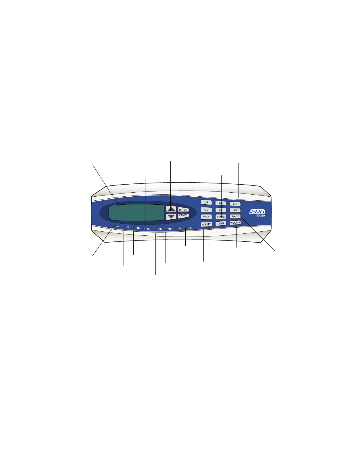
3. REVIEWING THE FRONT PANEL DESIGN
The front panel contains the LCD display window, status LEDs, and keypad buttons. The LEDs provide
visual information about the IQ 310 base unit and any option module that may be installed. Figure 1
identifies the LCD display window, the LEDs, and the keypad buttons.
LCD Window
RS LED
TD LED
CS LED
Up and Down arrows
RD LED
ALM LED
ERR LED
Enter
DBU LED
TST LED
Cancel
Next Key
Shift
Prev Key
Figure 1. IQ 310 Front Panel Layout
LCD Window
Displays menu items and messages in this 2 line by 16 character display.
Numeric Keypad
Quick Key
Delete Key
Add Key
Enter Key
Selects active menu items. To activate a menu item, scroll to it using the arrow keys or press the number of
the item. The flashing cursor indicates the active parameter. Press
<ENTER> to select the active menu item.
Up and Down Arrow Keys
Scrolls through the menu and activates the menu items of the current menu. The flashing cursor indicates
an active parameter.
61203800L1-1A © 2004 ADTRAN, Inc. 21
Page 22

Section 2, Engineering Guidelines IQ 310 System Manual
Cancel Key
Press the CANCEL key to stop the current activity and return to the previous menu. Press repeatedly until
the desired menu level is reached. When a submenu item is displayed, press
CANCEL to exit the current
display and return to the previous menu.
Quick Key
Pressing the QUICK key returns the front panel to the Main menu.
Numeric Keypad
The numeric keypad contains the numbers 0 through 9 and alpha characters A through F, which are used to
activate menu items and enter information such as the IP address.
Next, Prev, Add, Delete Keys
To activate these functions, press and release the SHIFT key, then press the NEXT, PREV, ADD, or
DELETE key. Use these keys when editing tables such as the PVC Options table.
Shift Key
Enter alpha characters by first pressing and releasing the SHIFT key and then pressing the desired
character. The
NEXT, PREV, ADD, and DELETE keys are also activated by first pressing SHIFT.
To activate a menu item designated by an alpha character rather than a number, place the cursor on the
menu item using the up and down arrows or press and release
cursor indicates the active parameter. Press
<ENTER> to select the item.
SHIFT and then press the letter. The flashing
Front Panel LEDs
With the IQ 310 powered-up, the front panel LEDs provide visual information about the status of the
IQ 310 and any option modules that may be installed. Table 1 provides detailed information about the front
panel LEDs.
Table 1. IQ 310 LEDs
For these LEDs... This color light... Indicates that...
RS (Request to Send) Green there is an active RS signal on DTE interface.
CS (Clear to Send) Green there is an active CS signal on DTE interface.
TD (Transmit Data) Green (flashes) there is transmit data activity on the DTE interface.
RD (Receive Data) Green (flashes) there is receive data activity on the DTE interface.
ERR (Error) Red (flashes) there is an active T1 line code violation or T1 path code
violation.
22 © 2004 ADTRAN, Inc. 61203800L1-1A
Page 23
IQ 310 System Manual Section 2, Engineering Guidelines
Table 1. IQ 310 LEDs (Continued)
For these LEDs... This color light... Indicates that...
ALM (Alarm) Red one of the following alarm conditions exists:
• Loss of signal
• Loss of T1 frame sync (red alarm)
• Receiving AIS (alarm indication signal) from the service
provider
• Frame Relay signaling is down.
TST (Test) Amber the network interface is in a loopback condition triggered
locally or from the service provider.
DBU (Dial Backup) Red the unit is in dial backup.
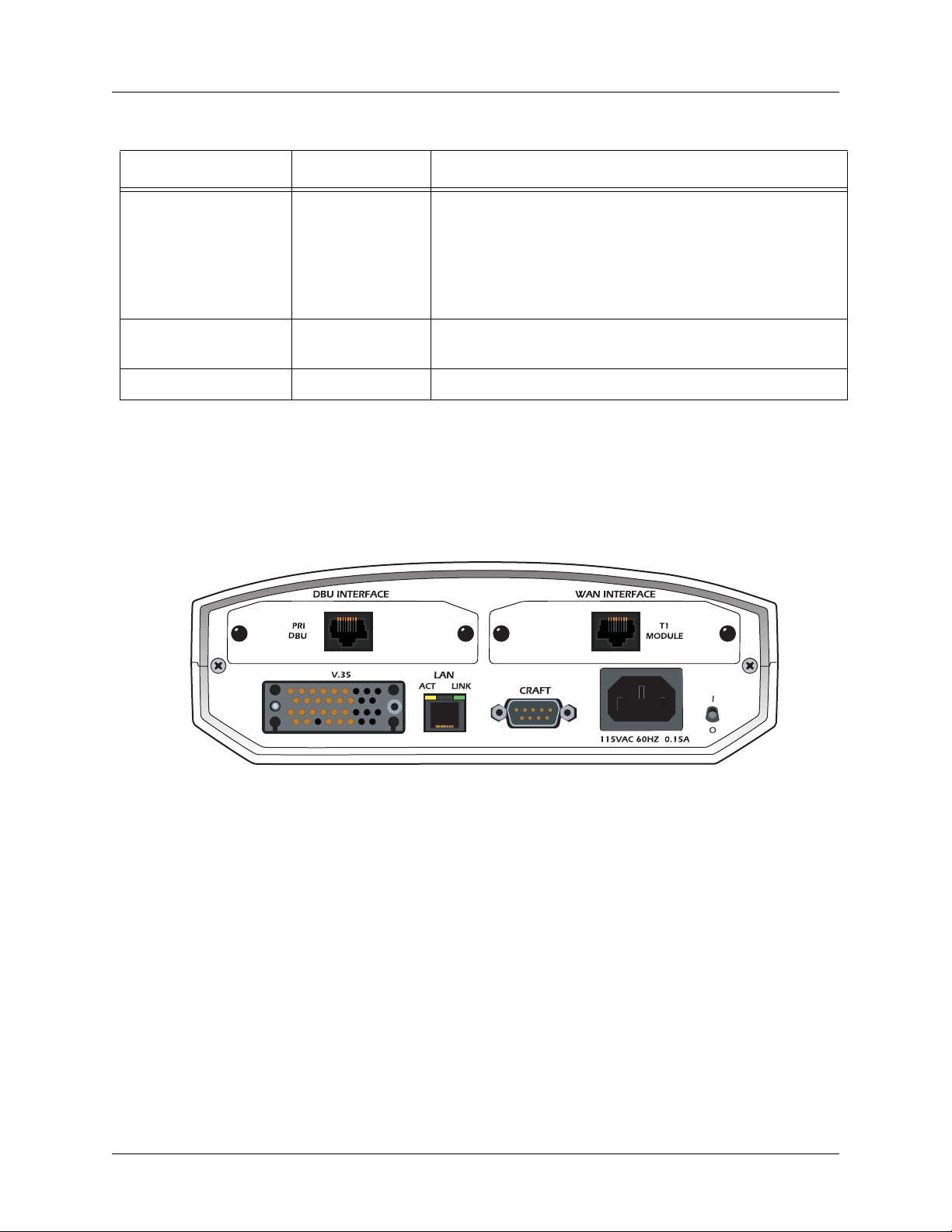
4. REVIEWING THE REAR PANEL DESIGN
The IQ 310 rear panel contains two expansion slots (one for Dial Backup and one for a Network Interface
Module), a DTE connector which provides primary channel V.35, and an Ethernet 10BaseT port for
management applications (see Figure 2).
Figure 2. IQ 310 Rear Panel
V.35 Nx56/64 Connector
The DTE should be connected to the V.35 connector (labeled V.35 ) with a maximum cable length of 100 feet.
Table 2 on page 24 shows the pinout for the V.35 Winchester-style connector.
61203800L1-1A © 2004 ADTRAN, Inc. 23
Page 24

Section 2, Engineering Guidelines IQ 310 System Manual
Table 2. V.35 Winchester Pinout
Pin CCITT DESCRIPTION
A 101 Protective ground (PG)
B 102 Signal ground (SG)
C 105 Request to send (RTS) from DTE
D 106 Clear to send (CTS) to DTE
E 107 Data set ready (DSR) to DTE
F 109 Received line signal detector (DCD) to DTE
H — Data terminal ready (DTR) from DTE
J — Ring indicator (RI)
R 104 Received data (RD-A) to DTE
T 104 Received data (RD-B) to DTE
V 115 RX clock (RC-A) to DTE
X 115 RX clock (RC-B) to DTE
P 103 Transmitted data (TD-A) from DTE
S 103 Transmitted data (TD-B) from DTE
Y 114 TX clock (TC-A) to DTE
AA 114 TX clock (TC-B) to DTE
U 113 External TX clock (ETC-A) from DTE
W 113 External TX clock (ETC-B) from DTE
NN — Test mode (TM) to DTE
CRAFT/CONTROL Port (DB-9)
The CRAFT/CONTROL port (EIA-232) connects to a computer or modem or to a VT100 terminal. The
CRAFT/CONTROL port input provides the following functions:
• Accepts EIA-232 input from a PC or a modem for controlling the IQ 310
• Operates at 9600, 19200, 38400, or 57600 bps
• Acts as input for either VT100 terminal or PC control
• Acts as an interface for flash memory software downloads using XMODEM
Table 3 on page 25 shows
24 © 2004 ADTRAN, Inc. 61203800L1-1A
CRAFT/CONTROL pinout.
Page 25

IQ 310 System Manual Section 2, Engineering Guidelines
.
Table 3. CRAFT/CONTROL Pinout
PIN NAME DESCRIPTION
1 DCD Carrier detect
2 RD Data received by the IQ 310
3 TD Data transmitted by the IQ 310
4 DTR Data terminal ready
5 GND Ground - connected to unit chassis
6 DSR Data set ready
7 RTS Request to send - flow control
8 CTS Clear to send - flow control
9 UNUSED —
LAN Ethernet Connection (RJ-48C)
The LAN port provides a 10BaseT Ethernet connection, which is used for IP Routing, TFTP, SNMP, and
Telnet connection. Table 4 shows the pinout.
Table 4. LAN Ethernet Pinout
PIN NAME DESCRIPTION
1 TX1 Transmit positive
2 TX2 Transmit negative
3 RX1 Receive positive
4, 5 UNUSED —
6 RX2 Receive negative
7, 8 UNUSED —
5. NETWORK INTERFACE MODULES
The IQ 310 provides two expansion slots that allow different types of interfaces to be used. The following
is a discussion of the available Network Interface Modules.
56k/64k Network Interface Module – RJ-48S (P/N 1202801L1)
The 56k/64k Network Interface Module provides a single 8-position modular jack to connect to the DDS
network. The 56k/64k Network Interface Module provides the following functions:
• Network performance monitoring and reporting
• Extensive self-testing
Table 5 on page 26 shows the 56k/64k NIM pinout.
61203800L1-1A © 2004 ADTRAN, Inc. 25
Page 26

Section 2, Engineering Guidelines IQ 310 System Manual
Table 5. 56k/64k Network Interface Module Pinout
PIN NAME DESCRIPTION
1 R1 Transmit data toward the network - Ring 1
2 T1 Transmit data toward the network - Tip 1
3 UNUSED —
4 UNUSED —
5 UNUSED —
6 UNUSED —
7 T Receive data from the network - Tip
8 R Receive data from the network - Ring
T1/FT1 Network Interface Module – RJ-48C (P/N 1202802L1)
The T1/FT1 Network Interface Module provides a single T1 port and complies with the applicable ANSI
®
and AT&T
standards. The T1/FT1 Network Interface Module provides the following functions:
• AMI or B8ZS coding
• Manual line build-out
• D4 or ESF framing
• Network performance monitoring and reporting
• Test loopbacks
• Extensive self-testing
Table 6 shows the T1/FT1 NIM pinout.
Table 6. T1/FT1 Network Interface Module Pinout
PIN NAME DESCRIPTION
1 R1 RXDATA-RING Receive data from the network
2 T1 RXDATA-TIP Receive data from the network
3 — UNUSED —
4 R TXDATA-RING Transmit data toward the network
5 T TXDATA-TIP Transmit data toward the network
6, 7, 8 — UNUSED —
26 © 2004 ADTRAN, Inc. 61203800L1-1A
Page 27

IQ 310 System Manual Section 2, Engineering Guidelines
T1/FT1 + DSX-1 Network Interface Module – RJ-48C (P/N 1202803L1)
The T1/FT1 + DSX-1 Network Interface Module provides one T1 port and one DSX-1 port and complies
®
with the applicable ANSI and AT&T
provides the following functions:
• AMI or B8ZS coding
• Manual line build-out
• D4 or ESF framing
• Network performance monitoring and reporting
• Test loopbacks
• Extensive self-testing
The pinouts for the T1/FT1 + DSX-1 NIM T1 and DSX-1 ports are shown in Table 7 and Table 8 below.
Table 7. T1/FT1 + DSX-1 Network Interface Module Pinout (T1 Port)
PIN NAME DESCRIPTION
1 R1 RXDATA-RING Receive data from the network
2 T1 RXDATA-TIP Receive data from the network
standards. The T1/FT1 + DSX-1 Network Interface Module
3 — UNUSED —
4 R TXDATA-RING Transmit data toward the network
5 T TXDATA-TIP Transmit data toward the network
6, 7, 8 — UNUSED —
Table 8. T1/FT1 + DSX-1 Network Interface Module Pinout (DSX Port)
PIN NAME DESCRIPTION
1 R1 TXDATA-RING Transmit data toward the PBX
2 T1 TXDATA-TIP Transmit data toward the PBX
3 — UNUSED —
4 R RXDATA-RING Receive data from the PBX
5 T RXDATA-TIP Receive data from the PBX
6, 7, 8 — UNUSED —
61203800L1-1A © 2004 ADTRAN, Inc. 27
Page 28

Section 2, Engineering Guidelines IQ 310 System Manual
T1 Probe Network Interface Module - RJ-48C (P/N 1202804L1)
The T1 Probe Network Interface Module provides a T1 NETWORK interface and a T1 DTE interface. The
T1 Probe complies with the applicable ANSI and AT&T
• AMI or B8ZS coding
• Manual line build-out
• D4 or ESF framing
• Network performance monitoring and reporting
• Test loopbacks
• Extensive self-testing
Table 9 and Table 10 show the T1 Probe NIM pinout.
Table 9. T1 Network (RJ-48C) Connection Pinout
Pin Name Description
1 R1 Receive data from the network
2 T1 Receive data from the network
®
standards and provides the following functions:
3 — UNUSED
4 R Transmit data toward the network
5 T Transmit data toward the network
6-8 — UNUSED
Table 10. DTE Interface (RJ-48C) Pinout
Pin Name Description
1 R1 Transmit data toward the DTE device
2 T1 Transmit data toward the DTE device
3 — UNUSED
4 R Receive data from the DTE device
5 T Receive data from the DTE device
6. DIAL BACKUP INTERFACE MODULES
The IQ 310 provides two expansion slots that allow different types of interfaces to be used. The following
is a discussion of the available Dial Backup Interface Modules.
28 © 2004 ADTRAN, Inc. 61203800L1-1A
Page 29

IQ 310 System Manual Section 2, Engineering Guidelines
V.34 DBU Module (P/N 1204002L3)
The following table shows the pinouts for the V.34 DBU Module.
Table 11. V.34 DBU Module Pin Assignments
Pin Name Description
1-3 - Not used
4 T Network-Tip
5 R Network-Ring
6-8 - Not used
ISDN BRI DBU Module (P/N 1204004L2)
The following table shows the pinouts for the ISDN BRI DBU Module.
Table 12. ISDN BRI DBU Module Pin Assignments
Pin Name Description
1-3 - Not used
4 T Network-Tip
5 R Network-Ring
6-8 - Not used
ISDN PRI DBU Module (P/N 1204008L2)
The following table shows the pinouts for the ISDN PRI DBU Module.
Table 13. ISDN PRI DBU Module Pin Assignments
Pin Name Description
1 R1 RXDATA-RING Receive data from the network
2 T1 RXDATA-TIP Receive data from the network
3 UNUSED --
4 R TXDATA-RING Send data toward network
5 T TXDATA-TIP Send data toward network
6,7,8 UNUSED --
61203800L1-1A © 2004 ADTRAN, Inc. 29
Page 30

Section 2, Engineering Guidelines IQ 310 System Manual
External DCE DBU Module (P/N 1204006L2)
The following table shows the pinouts for the DCE DBU Module.
Table 14. DCE Connector Pin Assignments
DB25 Pin# V.35 Pin# Function DTE Port Direction DCE Port Direction
1 A FGND
2 TD(EIA-232) I O
3 RD(EIA-232) O I
4 C RTS I O
5 D CTS O I
6 E DSR O I
7 B GND
8 F DCD O I
9 NEG
10 POS
11 AA TC-B(V.35) O I
12 Y TC-A(V.35) O I
13 V RC-A(V.35) O I
14 T RC-B(V.35) O I
15 TC(EIA-232) O I
16 R RD-A(V.35) O I
17 RC
18 S TD-B(V.35) I O
19 P TD-A(V.35) I O
20 H DTR I O
21 W ETC-B(V.35) I O
22 - - - -
23 U ETC-A(V.35) I O
24 ETC(EIA-232) I O
25 X RC-B(V.35) O I
The IQ 310 External DCE Module DB-25 interface supports EIA-232 or V.35.
V.35 requires an external DCE V.35 adapter cable (male DB-25 to male V.35,
P/N 1200193L1; or male DB-25 to female V.35, P/N 1200194L1).
30 © 2004 ADTRAN, Inc. 61203800L1-1A
Page 31

NETWORK TURNUP PROCEDURE
Provides shipment contents list, grounding instructions, mounting options, and specifics of supplying
power to the unit.
CONTENTS
Introduction . . . . . . . . . . . . . . . . . . . . . . . . . . . . . . . . . . . . . . . . . . . . . . . . . . . . . . . . . . . . . . . . . . . . 32
Unpack and Inspect the SYSTEM . . . . . . . . . . . . . . . . . . . . . . . . . . . . . . . . . . . . . . . . . . . . . . . . . .32
Contents of ADTRAN Shipments . . . . . . . . . . . . . . . . . . . . . . . . . . . . . . . . . . . . . . . . . . . . . . . . 32
Grounding Instructions . . . . . . . . . . . . . . . . . . . . . . . . . . . . . . . . . . . . . . . . . . . . . . . . . . . . . . . . . . 33
Supplying Power to the Unit . . . . . . . . . . . . . . . . . . . . . . . . . . . . . . . . . . . . . . . . . . . . . . . . . . . . . . 33
Mounting Options . . . . . . . . . . . . . . . . . . . . . . . . . . . . . . . . . . . . . . . . . . . . . . . . . . . . . . . . . . . . . . . 34
Installing Network and Dial Backup Interface Modules . . . . . . . . . . . . . . . . . . . . . . . . . . . . . . . . 34
Instructions for Installing the IQ 310 Network and Dial Backup Interface Modules. . . . . . . . . . . 35
56k/64k Network Interface Module (P/N 1202801L1) . . . . . . . . . . . . . . . . . . . . . . . . . . . . . . . . . 35
T1/FT1 Network Interface Module (P/N 1202802L1) . . . . . . . . . . . . . . . . . . . . . . . . . . . . . . . . . 35
T1/FT1 + DSX-1 Network Interface Module (P/N 1202803L1) . . . . . . . . . . . . . . . . . . . . . . . . . . 35
T1 Probe Network Interface Module (P/N 1202804L1) . . . . . . . . . . . . . . . . . . . . . . . . . . . . . . . . 36
61203800L1-1A © 2004 ADTRAN, Inc. 31
Page 32

Section 3, Network Turnup Procedure IQ 310 System Manual
1. INTRODUCTION
This section discusses installation of the IQ 310 system.
To prevent electrical shock, do not install equipment in a wet location or during a
lightning storm.
Electronic modules can be damaged by static electrical discharge. Before handling
modules, wear an antistatic discharge wrist strap to prevent damage to electronic
components. Place modules in antistatic packing material when transporting or storing.
When working on modules, always place them on an approved antistatic mat that is
electrically grounded.
2. UNPACK AND INSPECT THE SYSTEM
Each IQ 310 is shipped in its own cardboard shipping carton. Open each carton carefully and avoid deep
penetration into the carton with sharp objects.
After unpacking the unit, inspect it for possible shipping damage. If the equipment has been damaged in
transit, immediately file a claim with the carrier, then contact ADTRAN Customer Service (see Warranty
and Customer Service Information in the front of this manual).
Contents of ADTRAN Shipments
Your ADTRAN shipment includes the following items:
• The IQ 310 base unit
•The IQ 310 System CD including the System Manual and ADTRAN Utilities
• RJ-45 to RJ-45 cable - ADTRAN P/N 3127004
• AC power cord - ADTRAN P/N 3127031
• Network Interface Module and appropriate contents (depending on system level part number)
– 4203801L1 IQ 310 with 56k/64k Network Interface Module
– 4203802L1 IQ 310 with T1 Network Interface Module
– 4203803L1 IQ 310 with T1 with DSX Network Interface Module
– 4203804L1 IQ 310 with T1 Probe Network Interface Module
Refer to the individual Network Interface Module shipping contents on page 35 for
additional information.
32 © 2004 ADTRAN, Inc. 61203800L1-1A
Page 33

IQ 310 System Manual Section 3, Network Turnup Procedure
3. GROUNDING INSTRUCTIONS
The following provides grounding instruction information from the Underwriters’ Laboratory UL 60950
Standard for Safety of Information Technology Equipment Including Electrical Business Equipment, of
December, 2000.
An equipment grounding conductor that is not smaller in size than the ungrounded branch-circuit supply
conductors is to be installed as part of the circuit that supplies the product or system. Bare, covered, or
insulated grounding conductors are acceptable. Individually covered or insulated equipment grounding
conductors shall have a continuous outer finish that is either green, or green with one or more yellow
stripes. The equipment grounding conductor is to be connected to ground at the service equipment.
The attachment-plug receptacles in the vicinity of the product or system are all to be of a grounding type,
and the equipment grounding conductors serving these receptacles are to be connected to earth ground at
the service equipment. A supplementary equipment grounding conductor shall be installed between the
product or system and ground that is in addition to the equipment grounding conductor in the power supply
cord.
The supplementary equipment grounding conductor shall not be smaller in size than the ungrounded
branch-circuit supply conductors. The supplementary equipment grounding conductor shall be connected
to the product at the terminal provided, and shall be connected to ground in a manner that will retain the
ground connection when the product is unplugged from the receptacle. The connection to ground of the
supplementary equipment grounding conductor shall be in compliance with the rules for terminating
bonding jumpers at Part K or Article 250 of the National Electrical Code, ANSI/NFPA 70. Termination of
the supplementary equipment grounding conductor is permitted to be made to building steel, to a metal
electrical raceway system, or to any grounded item that is permanently and reliably connected to the
electrical service equipment ground.
The supplemental grounding conductor shall be connected to the equipment using a number 8 ring terminal
and should be fastened to the grounding lug provided on the rear panel of the equipment. The ring terminal
should be installed using the appropriate crimping tool (AMP P/N 59250 T-EAD Crimping Tool or
equivalent).
• This unit shall be installed in accordance with Article 400 and 364.8 of the NEC NFPA
70 when installed outside of a Restricted Access Location (i.e., central office, behind a
locked door, service personnel only area).
• Power to the IQ 310 must be from a grounded 115 VAC, 60 Hz source.
• The power receptacle uses double-pole, neutral fusing.
o
• Maximum recommended ambient operating temperature is 50
C.
4. SUPPLYING POWER TO THE UNIT
The AC-powered IQ 310 comes equipped with a detachable 8-foot power cord with a 3-prong plug for
connecting to a grounded power receptacle. As shipped, the IQ 310 is set to factory default conditions.
After installing the base unit and any option modules, the IQ 310 is ready for power-up. To power-up the
unit, ensure that the unit is properly connected to an appropriate power source and turn on the unit using
the on/off switch on the rear panel.
61203800L1-1A © 2004 ADTRAN, Inc. 33
Page 34

Section 3, Network Turnup Procedure IQ 310 System Manual
5. MOUNTING OPTIONS
The IQ 310 base unit may be installed for tabletop, 19-inch or 23-inch rack mount, or wall mount
configuration. Shelves may be purchased from ADTRAN to achieve the rack mount configuration.
Be careful not to upset the stability of the equipment mounting rack when installing this
product.
6. INSTALLING NETWORK AND DIAL BACKUP INTERFACE MODULES
Figure 1 shows the option slot numbering designation as viewed from the rear of the IQ 310. The network
slot accepts only IQ 310 Network Interface Modules, and the DBU slot accepts any of the IQ Series Dial
Backup Interface Modules.
DBU Slot
Network Slot
Figure 1. IQ 310 Slot Designation (Rear Panel)
Option modules are intended to be serviced by qualified service personnel only.
Modules are not hot swappable.
34 © 2004 ADTRAN, Inc. 61203800L1-1A
Page 35

IQ 310 System Manual Section 3, Network Turnup Procedure
Instructions for Installing the IQ 310 Network and Dial Backup Interface Modules
Instructions for Installing the IQ 310 Option Modules
Step Action
1. Power off the unit.
2. Remove the cover plate from the appropriate option slot of the IQ 310 rear panel.
3. Slide the option module into the option slot until the module is firmly seated against the front of
the chassis.
4. Secure the tabs at both edges of the module.
5. Connect the cables to the associated device(s).
6. Complete installation of remaining modules and base unit as specified in the appropriate
sections of this Network Turnup Procedure.
7. Power on the unit.
56k/64k Network Interface Module (P/N 1202801L1)
Shipping Contents
The ADTRAN shipment of the 56k/64k Network Interface Module includes the following items:
• 56k/64k Network Interface Module
• 56k/64k Network Interface Module Quick Start Guide
• RJ-45 to RJ-45 cable - ADTRAN P/N 3127004
T1/FT1 Network Interface Module (P/N 1202802L1)
Shipping Contents
The ADTRAN shipment of the T1/FT1 Network Interface Module includes the following items:
• T1/FT1 Network Interface Module
• T1/FT1 Network Interface Module Quick Start Guide
• RJ-45 to RJ-45 cable - ADTRAN P/N 3127004
T1/FT1 + DSX-1 Network Interface Module (P/N 1202803L1)
Shipping Contents
The ADTRAN shipment of the T1/FT1 + DSX-1 Network Interface Module includes the following items:
• T1/FT1 + DSX-1 Network Interface Module
• T1/FT1 + DSX-1 Network Interface Module Quick Start Guide
• Two RJ-45 to RJ-45 cables - ADTRAN P/N 3127004
61203800L1-1A © 2004 ADTRAN, Inc. 35
Page 36

Section 3, Network Turnup Procedure IQ 310 System Manual
T1 Probe Network Interface Module (P/N 1202804L1)
Shipping Contents
The ADTRAN shipment of the T1 Probe Network Interface Module includes the following items:
• T1 Probe Network Interface Module
• T1 Probe Network Interface Module Quick Start Guide
• Two RJ-45 to RJ-45 cables - ADTRAN P/N 3127004
36 © 2004 ADTRAN, Inc. 61203800L1-1A
Page 37

USER INTERFACE GUIDE
This section of ADTRAN’s IQ 310 System Manual is designed for use by network administrators and
others who will configure and provision the system. It contains information about navigating the VT100
user interface and using the front panel LCD display.
CONTENTS
Navigating the Terminal Menu . . . . . . . . . . . . . . . . . . . . . . . . . . . . . . . . . . . . . . . . . . . . . . . . . . . . 38
Terminal Menu Window . . . . . . . . . . . . . . . . . . . . . . . . . . . . . . . . . . . . . . . . . . . . . . . . . . . . . . . 38
Navigating Using the Keyboard Keys . . . . . . . . . . . . . . . . . . . . . . . . . . . . . . . . . . . . . . . . . . . . . 40
Terminal Menu and System Control . . . . . . . . . . . . . . . . . . . . . . . . . . . . . . . . . . . . . . . . . . . . . . . .41
Selecting the Appropriate Menu . . . . . . . . . . . . . . . . . . . . . . . . . . . . . . . . . . . . . . . . . . . . . . . . . 41
Menu Descriptions . . . . . . . . . . . . . . . . . . . . . . . . . . . . . . . . . . . . . . . . . . . . . . . . . . . . . . . . . . . . . . 42
Configuration Menus . . . . . . . . . . . . . . . . . . . . . . . . . . . . . . . . . . . . . . . . . . . . . . . . . . . . . . . . . . 42
Stats Menu . . . . . . . . . . . . . . . . . . . . . . . . . . . . . . . . . . . . . . . . . . . . . . . . . . . . . . . . . . . . . . . . . 60
Menu Viewing Options . . . . . . . . . . . . . . . . . . . . . . . . . . . . . . . . . . . . . . . . . . . . . . . . . . . . . . . . 60
Test Menu . . . . . . . . . . . . . . . . . . . . . . . . . . . . . . . . . . . . . . . . . . . . . . . . . . . . . . . . . . . . . . . . . . 78
Dial Menu . . . . . . . . . . . . . . . . . . . . . . . . . . . . . . . . . . . . . . . . . . . . . . . . . . . . . . . . . . . . . . . . . . 81
Utilities Menu. . . . . . . . . . . . . . . . . . . . . . . . . . . . . . . . . . . . . . . . . . . . . . . . . . . . . . . . . . . . . . . . 82
FIGURES
Figure 1. Top-Level Terminal Menu Window . . . . . . . . . . . . . . . . . . . . . . . . . . . . . . . . . . . . . . . . 38
Figure 2. Alternate Menu View . . . . . . . . . . . . . . . . . . . . . . . . . . . . . . . . . . . . . . . . . . . . . . . . . . . 39
Figure 3. Example of Interval View . . . . . . . . . . . . . . . . . . . . . . . . . . . . . . . . . . . . . . . . . . . . . . . . 61
Figure 4. Test Menu . . . . . . . . . . . . . . . . . . . . . . . . . . . . . . . . . . . . . . . . . . . . . . . . . . . . . . . . . . . 78
TABLES
Table 1. PRI Channel Descriptions . . . . . . . . . . . . . . . . . . . . . . . . . . . . . . . . . . . . . . . . . . . . . . . .75
61203800L1-1A © 2004 ADTRAN, Inc. 37
Page 38

Section 4 User Interface Guide IQ 310 System Manual
1. NAVIGATING THE TERMINAL MENU
Terminal Menu Window
The IQ 310 uses a multi-level menu structure that contains both menu items and data fields. All menu
items and data fields display in the terminal menu window (see Figure 1), through which you have
complete control of the IQ 310.
Menu Path
Login Type
Left Pane
System Name
Figure 1. Top-Level Terminal Menu Window
Network Status
Signaling Status
DBU Status
Right Pane
Navigation Help
Menu Path
The first line of the terminal menu window (the menu path) shows the session’s current position (path) in
the menu structure. For example, Figure 1 shows the top-level menu with the cursor on the
submenu; therefore, the menu path reads IQ 310
/CONFIGURATION.
CONFIGURATION
Window Panes
When you first start a terminal menu session, the terminal menu window is divided into left and right
panes. The left pane shows the list of available submenus, while the right pane shows the contents of the
currently selected submenu.
You can view the terminal windows in two ways: with fields and submenus displaying horizontally across
the right pane, or with fields and submenus displaying vertically down the right pane. Viewing submenus
vertically rather than horizontally allows you to see information at a glance rather than scrolling
horizontally across the window. To change the view, move your cursor to an index number and press
<ENTER>. Figure 2 shows this alternate view. Fields and submenu names may vary slightly in this view.
38 © 2004 ADTRAN, Inc. 61203800L1-1A
Page 39

IQ 310 System Manual Section 4 User Interface Guide
Figure 2. Alternate Menu View
Window Pane Navigation
Use the following chart to assist you in moving between and within the two window panes.
To do this... Press one of the following keys...
Ta b
Move from left pane to right pane
Move from right pane to left pane
Move within each pane
Right Window Pane Notation
Enter
Right arrow
Shift+Tab
Escape
Left arrow
Backspace
Up arrow
Down arrow
Left arrow
Right arrow
The right window pane shows the contents of the currently selected menu. These contents can include
both submenu items and data fields. Some submenus contain additional submenus and some data fields
contain additional data fields. The chart on the following page explains the notation used to identify
these additional items.
61203800L1-1A © 2004 ADTRAN, Inc. 39
Page 40

Section 4 User Interface Guide IQ 310 System Manual
This notation... Means that...
[+] More items are available when selected.
<+> An action is to be taken, such as activating a test.
Highlighted field You can enter data in this field.
Underlined field The field contains read-only information.
Additional Terminal Menu Window Features
• Login Type - Displays L when menu reflects the local unit, R for a remote unit, and T during a Telnet
session.
• System Name - Displays the name entered in the SYSTEM NAME field.
• Network Status - Displays the current state of the incoming network circuit.
• Signaling Status - Displays the current LMI state of the network interface.
• DBU Status - Displays the current state of the DBU service (available when a DBE module is installed).
• Navigation Help - Lists characters used for navigating the terminal menu <CTRL + Z>.
Navigating Using the Keyboard Keys
You can use various keystrokes to move through the terminal menu, to manage a terminal menu session,
and to configure the system. Press
<CTRL + Z> to activate a pop-up screen listing the navigation
keystrokes.
Moving through the Menus
To do this... Press this key...
Return to the home screen H
Select items Arrows
Edit a selected menu item Enter
Cancel an edit Escape
Close pop-up help screen Escape
Move between the left and right panes
Move to the top of a screen A
Move to the bottom of a screen Z
Ta b
Arrows
Ascend one menu level Backspace
40 © 2004 ADTRAN, Inc. 61203800L1-1A
Page 41

IQ 310 System Manual Section 4 User Interface Guide
Session Management Keystrokes
To do this... Press this key...
Log out of a session CTRL + L
Refresh the screen
To save time, only the portion of the screen that has changed is refreshed. This
option should only be necessary if the display picks up incorrect characters.
CTRL + R
Configuration Keystrokes
To do this... Press this key...
Insert a new list item.
For example, add a new item to the list by pressing <I> while the cursor is over the
index number.
Delete a list item.
For example, delete an item from the list by pressing <D> while the cursor is over
the index number.
I
D
Getting Help
Press <CTRL + Z> to activate a help screen that displays the available keystrokes you can use to navigate
the terminal menu.
2. TERMINAL MENU AND SYSTEM CONTROL
Selecting the Appropriate Menu
The terminal menu is the access point to all other operations. Each terminal menu item has several
functions and submenus that identify and provide access to specific operations and parameters. Use the
chart below to help select the appropriate terminal menu.
To do this... Go to this menu...
Set network operating parameters for the DTE, network, and dial backup
interfaces, to provision system options.
Display status information for the DTE port, network port, DBU port,
ETHERNET port, CRAFT/CONTROL port, and system.
Activate ping, Net and DTE loopback, and PVC loopback testing
functions.
Access dialing functions (only available when DBU module is installed). DIAL
Upgrade firmware. F
61203800L1-1A © 2004 ADTRAN, Inc. 41
C
ONFIGURATION
VIEW STATISTICS
TEST
IRMWARE UPGRADE
Page 42

Section 4 User Interface Guide IQ 310 System Manual
3. MENU DESCRIPTIONS
CONFIGURATION MENUS
The following PHYSICAL LAYER OPTIONS do not apply if the T1 Probe Network Interface
Module is installed.
CONFIGURATION > DTE PORT > PHYSICAL LAYER OPTIONS > FLOW CONTROL
This option determines how the IQ 310 responds to congestion during DBU operation.
NONE - No flow control is used and the IQ 310 drops frames during severe congestion while in DBU
operation.
HARDWARE - The IQ 310 varies the DTE TC clock as necessary to relieve congestion during DBU
operation.
FECN/BECN - While in a congested state during DBU operation, frames across the DBU PVCs have
FECN or BECN set depending on the direction. Frames outbound to the network have FECN set,
while frames inbound to the attached DTE device have BECN set. This method is useful if the
attached DTE devices can respond to congestion notification.
CONFIGURATION > DTE PORT > PHYSICAL LAYER OPTIONS > CTS OPTION
Set the CTS lead to FORCED ON or FOLLOW RTS.
FORCED ON - The CTS lead is always on and the RTS lead is ignored.
FOLLOW RTS - The CTS lead is on when the RTS lead is on (and off when the RTS lead is off).
CONFIGURATION > DTE PORT > PHYSICAL LAYER OPTIONS > DSR OPTION
Set the DSR lead to FORCED ON or NORMAL.
FORCED ON - The DSR lead is always on.
NORMAL - The DSR lead is off when the IQ 310 is in a loopback test or an alarm state.
CONFIGURATION > DTE PORT > PHYSICAL LAYER OPTIONS > CD OPTION
Set the CD lead to FORCED ON or NORMAL.
FORCED ON - The CD lead is always on.
NORMAL - The CD lead is off when the IQ 310 is in alarm state.
42 © 2004 ADTRAN, Inc. 61203800L1-1A
Page 43

IQ 310 System Manual Section 4 User Interface Guide
CONFIGURATION > DTE PORT > PHYSICAL LAYER OPTIONS > TC CLOCK OPTION
NORMAL - Clock for DTE's transmit data normal phase.
INVERTED - Clock for DTE's transmit data inverted phase. May be used in high speed circuits
(>512 kbps) when the DTE's V.35 interface has high delay. This is usually indicated by HDLC errors
on the IQ 310's DTE port.
The following DTE > FRAME RELAY OPTIONS applies to all Network Interface Modules.
CONFIGURATION > DTE PORT > FRAME RELAY OPTIONS
Use the following selections to configure timeout intervals and error thresholds, and to configure PVC
management settings.
CONFIGURATION > DTE PORT > FRAME RELAY OPTIONS > T392
Set the timeout (in seconds) between polling intervals. This parameter needs to be a few seconds longer
than the T391 setting of the attached frame relay device. Range is 5 to 30 seconds.
CONFIGURATION > DTE PORT > FRAME RELAY OPTIONS > N392 AND N393
These parameters define the error threshold for the UNI (user to network interface) formed by the IQ 310
DTE port and the attached frame relay device. If the error threshold is met, the signaling state status is
changed to down, which indicates a service-affecting condition. This condition is cleared once N393
consecutive error-free events are received. N392 defines the number of errors required in a given event
window, while N393 defines the number of polling events in each window.
For example:
If N392=3 and N393=4, then if three errors occur within any four events, the interface is determined
inactive.
The status of the connection can be viewed in the V
(see Stats Menu on page 60). The status returns to A
IEW STATISTICS > DTE PORT > SIGNAL STATE menu
CTIVE once the threshold is no longer exceeded.
61203800L1-1A © 2004 ADTRAN, Inc. 43
Page 44

Section 4 User Interface Guide IQ 310 System Manual
CONFIGURATION > DTE PORT > FRAME RELAY OPTIONS > MANAGEMENT DLCI
To use local PVC management, enter the management data link connection identifier (DLCI). The
ANAGEMENT DLCI is a special DLCI used between the attached DTE device and the IQ 310 to carry
M
SNMP and Telnet packets to/from the IQ 310 on the DTE port.
Guidelines for Configuring Management DLCI
If the attached router or FRAD is used to route SNMP/Telnet frames to the IQ 310, set the
M
ANAGEMENT DLCI to a unique value (between 16 and 1007) that identifies the virtual circuit
between the router/FRAD and the IQ 310. The router/FRAD must also be configured to route the
IQ 310 IP address to this DLCI. The IP A
also be set in the S
YSTEM CONFIGURATION menu.
DDRESS and SUBNET MASK for the DTE (V. 3 5 ) port must
CONFIGURATION > DTE PORT > FRAME RELAY OPTIONS > MANAGEMENT PVC OPTION
If this option is set to ENABLED, the management DLCI is included in the Full Status response to the
router. Enable this option when the management DLCI is used to route management traffic to the IQ 310.
Options are E
NABLED and DISABLED.
CONFIGURATION > DTE PORT > FRAME RELAY OPTIONS > SIGNALING RESPONSES
This option determines when PVC SIGNALING RESPONSES are sent to the router.
ALWAYS ON - If enabled, PVC SIGNALING RESPONSES are sent to the router regardless of the network
signaling state. Enable this option when the IQ 310 is used for dial backup.
FOLLOW NETWORK (FOLLOW NET) - If enabled, PVC SIGNALING RESPONSES are sent to the router
only when the network signaling state is up. Enable this option when the router is going to use an
alternate path for dial backup.
ALWAYS OFF - If enabled, PVC signaling responses are NOT sent to the router, regardless of the
network signaling state. Enable this option to simulate a PVC failure when the router is going to use
an alternate path for dial backup.
The following NETWORK > PHYSICAL LAYER OPTIONS are in groups based on the Network
Interface Module (NIM).
CONFIGURATION > NETWORK PORT > PHYSICAL LAYER OPTIONS > T1 + DSX NIM
CHANNEL MAP - This field allows the user to map each individual DS0 to the DSX-1 port or to the
DTE port, or to set it to IDLE.
DS01 . . . DS024 - Listing of individual DS0s in the Channel Map.
FRAMING FORMAT - Set the frame format for the network interface.
Choices:
44 © 2004 ADTRAN, Inc. 61203800L1-1A
D4, ESF, and AUTO.
Page 45

IQ 310 System Manual Section 4 User Interface Guide
D4 is equivalent to superframe format (SF).
LINE CODE - Set the line code for the network interface.
Choices:
CLOCK SOURCE - Select the clock source to be derived from the network or from the unit’s internal
AMI (alternate mark inversion) or B8ZS.
clock. The selected clocking option designates the clock source for transmission. Clocking necessary
for receiving data is recovered from incoming data. This option is most commonly set to
N
ETWORK.
Choices:
LINE BUILDOUT (LBO) - Select the line buildout for the network interface. In AUTO mode, the IQ 310
sets the
RX GAIN - Select the desired receiver sensitivity setting. The factory default is NORMAL, which is
INTERNAL and FROM NETWORK.
LBO based on the strength of the receive signal. Options: AUTO, 0, 7.5, 15, and 22.5 DB.
FROM
adequate for most applications. The extended setting should be used only in applications where the
NORMAL setting is not sufficient. If the receive signal strength is less than 30 dB, choose EXTENDED.
CHANNEL RATE - Set the channel bandwidth for 56 or 64 kbps.
TRANSMIT PRM - Enabling performance report messages (PRM) allows the IQ 310 to send messages
across the facility data link (FDL) per ANSI T1.403. The terminating device at the telco may use this
information for management of the T1 loop.The IQ 310 supports PRM messages per AT&T Pub
54016 which is a poll/response type protocol. Because of this poll/response nature, the transmit PRM
option does not disable the IQ 310 from processing or responding to 54016-type messages.
Choices:
YES or NO.
CONFIGURATION > NETWORK PORT > PHYSICAL LAYER OPTIONS > T1 NIM
FRAMING FORMAT - Set the frame format for the network interface.
Choices:
LINE CODE - Set the line code for the network interface.
Choices:
CLOCK SOURCE - Select the clock source to be derived from the network or from the unit’s internal
clock. The selected clocking option designates the clock source for transmission. Clocking necessary
for receiving data is recovered from incoming data. This option is most commonly set to
N
ETWORK.
Choices:
LINE BUILDOUT (LBO) - Select the line buildout for the network interface. In AUTO mode, the IQ 310
sets the
D4, ESF, and AUTO.
D4 is equivalent to superframe format (SF).
AMI (alternate mark inversion) or B8ZS.
INTERNAL and FROM NETWORK.
LBO based on the strength of the receive signal. Options: AUTO, 0, 7.5, 15, and 22.5 DB.
FROM
61203800L1-1A © 2004 ADTRAN, Inc. 45
Page 46

Section 4 User Interface Guide IQ 310 System Manual
RX GAIN- Select the desired receiver sensitivity setting. The factory default is NORMAL, which is
adequate for most applications. The extended setting should be used only in applications where the
NORMAL setting is not sufficient. If the receive signal strength is less than 30 dB, choose EXTENDED.
CHANNEL RATE - Set the channel bandwidth for 56 or 64 KBPS.
CHANNEL ALIGNMENT - This field allows the user to select the channel alignment to be CONTIGUOUS or
ALTERNATING.
START CHANNEL - Select the channel in which the T1 stream starts. The setting must be consistent
with the carrier if using a public network. The range is
NUMBER OF CHANNELS - Select the number of DS0s (channels) to be used. The range is 1 to 24.
TRANSMIT PRM - Enabling performance report messages (PRM) allows the IQ 310 to send messages
1 to 24.
across the facility data link (FDL) per ANSI T1.403. The terminating device at the telco may use this
information for management of the T1 loop.The IQ 310 supports PRM messages per AT&T Pub
54016 which is a poll/response type protocol. Because of this poll/response nature, the transmit PRM
option does not disable the IQ 310 from processing or responding to 54016-type messages.
Choices:
YES or NO.
CONFIGURATION > NETWORK PORT > PHYSICAL LAYER OPTIONS > 56/64K NIM
LOOP RATE - Set the loop rate for 56 KBPS, 64 KBPS, or AUTO.
CLOCK SOURCE - Configure the IQ 310 to derive clocking from itself (INTERNAL) or from the network.
The most common application is
FROM NETWORK.
CONFIGURATION > NETWORK PORT > PHYSICAL LAYER OPTIONS > T1 PROBE NIM
FRAMING FORMAT - Set the frame format for the network interface.
Choices:
LINE CODE - Set the line code for the network interface.
Choices:
CLOCK SOURCE - Select the clock source to be derived from the network or from the unit’s internal
clock. The selected clocking option designates the clock source for transmission. Clocking necessary
for receiving data is recovered from incoming data. This option is most commonly set to
N
ETWORK.
Choices:
LINE BUILDOUT (LBO) - Select the line buildout for the network interface. In AUTO mode, the IQ 310
sets the
Options:
RX SENSITIVITY - Select the desired receiver sensitivity setting. The factory default is NORMAL, which
is adequate for most applications. The extended setting should be used only in applications where the
NORMAL setting is not sufficient. If the receive signal strength is less than 30 dB, choose EXTENDED.
CHANNEL BANDWIDTH - Set the channel bandwidth for 56 or 64 KBPS.
D4, ESF, and AUTO.
AMI (alternate mark inversion) or B8ZS.
INTERNAL and FROM NETWORK.
LBO based on the strength of the receive signal.
AUTO, 0, 7.5, 15, and 22.5 DB.
FROM
46 © 2004 ADTRAN, Inc. 61203800L1-1A
Page 47

IQ 310 System Manual Section 4 User Interface Guide
CHANNEL ALIGNMENT - This field allows the user to select the channel alignment to be CONTIGUOUS or
ALTERNATING.
START CHANNEL -
with the carrier if using a public network. The range is
TRANSMIT PRM - Enabling performance report messages (PRM) allows the IQ 310 to send messages
Select the channel in which the T1 stream starts. The setting must be consistent
1 to 24.
across the facility data link (FDL) per ANSI T1.403. The terminating device at the telco may use this
information for management of the T1 loop.The IQ 310 supports PRM messages per AT&T Pub
54016 which is a poll/response type protocol. Because of this poll/response nature, the transmit PRM
option does not disable the IQ 310 from processing or responding to 54016-type messages.
Choices:
YES or NO.
The following NETWORK PORT and FRAME RELAY OPTIONS applies to all Network
Interface Modules.
CONFIGURATION > NETWORK PORT > FRAME RELAY OPTIONS > SIGNAL TYPE
Set the signaling type option to match the network signaling type. AUTO mode forces the IQ 310 to use the
same signaling type as the attached frame relay DTE. If A
attached, the IQ 310 uses ANSI T1.617-D signaling type.
Choices: N
ONE, LMI (gang of four), ANSI T1.617-D (Annex D), ITU-T Q.933-A (Annex A), or AUTO.
UTO is selected and there is no DTE device
CONFIGURATION > NETWORK PORT > FRAME RELAY OPTIONS > SIGNAL POLLS
Set the signal polls to either NORMAL or FOLLOWS DTE. If set to NORMAL, the signal state will reflect the
signal state of the network. If set to
FOLLOWS DTE, the signal state will reflect the signal state of the DTE
device.
CONFIGURATION > NETWORK PORT > FRAME RELAY OPTIONS > T391
Set the time (in seconds) between polls to the frame relay network.
CONFIGURATION > NETWORK PORT > FRAME RELAY OPTIONS > N391
Determine how many link integrity polls occur in between full status polls.
61203800L1-1A © 2004 ADTRAN, Inc. 47
Page 48

Section 4 User Interface Guide IQ 310 System Manual
CONFIGURATION > NETWORK PORT > FRAME RELAY OPTIONS > N392 AND N393
These parameters define the error threshold for the UNI formed by the IQ 310 network port and the frame
relay switch. If the error threshold is met, the signaling state is changed to down, which indicates a
service-affecting condition. This condition is cleared once N393 consecutive error-free events are received.
N392 defines the number of errors required in a given event window, while N393 defines the number of
polling events in each window.
For example:
If N392=3 and N393= 4, then if three errors occur within any four events the interface is determined
inactive.
The status of the connection can be viewed in the S
S
TATE. The status will return to active again once the threshold is no longer exceeded.
TATISTICS menu under NETWORK PORT SIGNALING
The network service provider should recommend the values entered into the T391, N391,
N392, and N393 fields.
CONFIGURATION > NETWORK PORT > MANAGEMENT DLCI 1 AND DLCI 2
Enter the management data link connection identifiers (DLCIs). These DLCIs are used to carry
management traffic to and from the network.
CONFIGURATION > NETWORK PORT > MGMT DLCI 1 AND DLCI 2 MODE
Set to DEDICATED if the management DLCI is used only to manage the IQ 310 (and not used to carry
customer traffic). If set to D
EDICATED, the router is not notified of that DLCI. Set to SHARED if the
management DLCI is used for carrying customer traffic and management data.
CONFIGURATION > NETWORK PORT > MAXIMUM PVC COUNT
Set the maximum number of PVCs that the IQ 310 will monitor for statistical information. This value
determines the amount of history intervals available for storage. To get the maximum amount of statistical
history storage, set this value equal to the number of PVCs assigned to the frame relay port. A smaller
value increases history interval count.
CONFIGURATION > NETWORK PORT > HISTORY INTERVAL COUNT
Set the number of history intervals to store for statistics. History intervals are displayed in the INTERVAL
portions of the S
the H
ISTORY INTERVAL SIZE field. The HISTORY INTERVAL COUNT field determines how many intervals
can be stored at a time. The maximum value allowed is affected by the M
(previously described).
48 © 2004 ADTRAN, Inc. 61203800L1-1A
TATISTICS menus. These views provide data grouped by the interval of time selected in
AX PVC COUNT selection
Page 49

IQ 310 System Manual Section 4 User Interface Guide
CONFIGURATION > NETWORK PORT > PVC CONFIG
The information in this menu must be entered for each PVC. DLCI numbers and their corresponding CIRs
are provided by the service provider.
The following NETWORK PORT > PVC CONFIG options are not applicable if the T1 Probe
NIM is installed.
When configuring PVC options using the front panel the NEXT, PREV, ADD, and DELETE
keys are used.
CONFIGURATION > NETWORK PORT > PVC CONFIG > DLCI
Enter the Network DLCI.
Range: 16 to 1007.
CONFIGURATION > NETWORK PORT > PVC CONFIG > DBU DLCI
Enter the far end DLCI for each PVC used for dial backup. Only the IQ 310 that originates the call is
required to have this option set. These options are only available if a DBU module is installed.
The range for the DBU DLCI field is from 16 to 1007. Therefore, you cannot manually enter 0 for the
PVCs not used in DBU. When an entry is first created with the A
reset a previously configured DBU DLCI to 0, delete the entry and then add it back in (using the D
DD selections).
and A
Only PVCs that are used in DBU should have the DBU DLCI set to a non-zero value.
The PVC CONFIG > DBU PHONE NUMBER, DBU CALL ORDER, and DBU ON INACTIVE options
are only available if a DBU module is installed. However, they are not available with the
DCE DBU module installed.
DD selection, it is set to 0 by default. To
ELETE
61203800L1-1A © 2004 ADTRAN, Inc. 49
Page 50

Section 4 User Interface Guide IQ 310 System Manual
CONFIGURATION > NETWORK PORT > PVC CONFIG > DBU PHONE NUMBER
The phone number entry stores the phone number that is used when the IQ 310 triggers auto DBU in case
of port or PVC failure. The phone number should correspond to a location that is equipped with an “Adtran
Safety Net” device that is capable of restoring the PVC which is designated by the DBU DLCI element.
If auto DBU is triggered by port failure, then the DBU Call Order element determines the order of a dialing
list for alternate backup locations.
CONFIGURATION > NETWORK PORT > PVC CONFIG > DBU CALL ORDER
This determines the order in which a list of backup locations will be dialed. This applies only to auto dial
backup processes that are triggered by port failure. If all DBU Call Order entries are set to N
ONE, then the
first entry with a DBU phone number will be used.
CONFIGURATION > NETWORK PORT > PVC CONFIG > DBU ON INACTIVE
This option works in conjunction with the dial backup criteria option WITH PVC INACTIVE. For the
ON INACTIVE option to have an affect on auto DBU operation, the WITH PVC INACTIVE option must
DBU
be set to E
NABLE.
If DBU
or unknown state, the IQ 310 will dial the phone number designated by the DBU
ON INACTIVE is set for ENABLED and the PVC designated by the DLCI element goes to an inactive
PHONE NUMBER element
in the table entry.
G
ROUP is a special case in which all PVCs that are part of a group must be in an inactive or unknown state
before the auto DBU process is triggered. This special case is treated as a port failure in which the DBU
C
ALL ORDER entry applies.
CONFIGURATION > NETWORK PORT > PVC OPTIONS > CIR (KBPS)
Enter the CIR (committed information rate) in kbps for the corresponding DLCI. The information is
provided by your service provider and must be entered for each PVC.
The following PVC OPTIONS are applicable to all Network Interface Modules.
CONFIGURATION > NETWORK PORT > PVC OPTIONS > SEQ NUM CHECKING
Set to ENABLE only if there is an IQ or ATLAS product on the other end of the PVC. When enabled, the
IQ 310 tags each frame with a sequence number which is then used by the remote IQ or ATLAS unit to
detect lost packets. Lost packet counts are given in the S
TATISTICS menus.
CONFIGURATION > NETWORK PORT > PVC OPTIONS > DELAY MEASUREMENT
Set to ENABLE only if there is an IQ or ATLAS product on the other end of the PVC. When enabled, the
IQ 310 periodically transmits a loopback frame to the remote IQ or ATLAS unit which is then returned to
measure round trip delay of each PVC. Minimum, maximum, and average delay measurements are given
in the S
50 © 2004 ADTRAN, Inc. 61203800L1-1A
TATISTICS menus.
Page 51

IQ 310 System Manual Section 4 User Interface Guide
CONFIGURATION > NETWORK PORT > PVC OPTIONS > STATS OPTION
This option prioritizes PVCs for STATISTICS counts. The IQ 310 tracks statistics for a limited number of
the PVCs that pass through. This number is determined in the M
for this field are described below:
UTO - If set to AUTO, then statistics will be logged for this PVC if the MAX PVC COUNT has not been
A
exceeded. The
ENABLED - If set to ENABLED, then statistics will be logged for this PVC if the MAX PVC COUNT has
not been exceeded. A PVC set to
DISABLED - If set to DISABLED, then statistics will not be logged for this PVC at any time.
AUTO selection designates a PVC as second priority to a PVC set to ENABLED.
ENABLED is designated as a higher priority than one set to AUTO.
If the IQ 310 encounters a PVC that has not been entered into the PVC OPTIONS table, the
PVC is set to
AUTO by default.
AX PVC COUNT field. The three choices
The following DSX PORT and DIAL BACKUP options do not apply to the T1 Probe NIM.
CONFIGURATION > DSX PORT > FRAMING FORMAT
Set the frame format for the DSX-1 interface. These options are only available if a T1/DSX network
interface module is installed.
Choices:
D4, ESF, and AUTO.
CONFIGURATION > DSX PORT > LINE CODE
Set the line code for the DSX-1 interface. These options are only available if a T1/DSX network interface
module is installed.
Choices:
AMI (alternate mark inversion) or B8ZS.
CONFIGURATION > DSX PORT > YELLOW ALARM
YEL ALARM enables and disables the transmitting of yellow alarms. These options are only available if a
T1/DSX network interface module is installed.
Choices:
ENABLE, DISABLE
CONFIGURATION > DSX PORT > LINE LENGTH
LINE LENGTH provides selection of the proper output level for the DSX-1 based on the length of the
interface cable. These options are only available if a T1/DSX network interface module is installed.
Choices:
1-133 FT, 133-266 FT, 266-399 FT, 399-533 FT, 533-655 FT, 7.5 DB
61203800L1-1A © 2004 ADTRAN, Inc. 51
Page 52

Section 4 User Interface Guide IQ 310 System Manual
CONFIGURATION > DSX PORT > IN-BAND LOOPBACK
INBAND LOOPBACK sets the DSX-1 to accept or reject in-band loopup or loopdown codes (per ANSI T1.403
specification) which may be sent to the module over the DSX-1 interface. This loopback is a line loopback.
These options are only available if a T1/DSX network interface module is installed.
Choices:
ACCEPT, REJECT
CONFIGURATION > DSX PORT > ROBBED BIT SIGNALING
This menu option is used to enable/disable robbed-bit signaling. Whenever the DSX-1 interface is
connected to terminal equipment (i.e., PBX/SW56) for voice or dialed data services, this option should be
enabled. The only exception is when the terminal equipment is using a form of common channel signaling
(i.e., PRI). These options are only available if a T1/DSX network interface module is installed.
Choices:
ENABLE, DISABLE
CONFIGURATION > DIAL BACKUP > AUTO DBU
The AUTOMATIC DBU option specifies whether the unit automatically enters dial backup mode or waits
for manual setup. The factory default setting is D
ISABLE. This option is only available with the DBU
module installed.
CONFIGURATION > DIAL BACKUP > DBU OPTIONS > ANSWER/ORIGINATE
This option is only available when the frame relay signaling is set to none. When using a non-frame relay
circuit, one unit must be set to originate the DBU call and the other unit must be set to answer the call. This
option is only available with the DBU module installed.
CONFIGURATION > DIAL BACKUP > DBU OPTIONS > ANSWER ALWAYS
If this feature is enabled, the unit will answer a call. If disabled, it will not answer a call. However, the
ANSWER ALWAYS option must work in conjunction with the AUTO DBU and ORIGINATE/ANSWER options.
AUTO DBU option is the controlling option and if it is disabled, the unit will not answer the call
The
regardless of how
of the
AUTO DBU setting. The ORIGINATE/ANSWER feature only appears when the unit is programmed for a
nonframe-relay circuit (signaling none). If both
answer the call even if it is set to
ANSWER ALWAYS is set, except for the DCE DBU which will answer the call regardless
ANSWER ALWAYS and AUTO DBU are enabled, the unit will
ORIGINATE.
The
ANSWER ALWAYS option is only available with the DBU module installed. This option is not available
with DCE or PRI DBU modules installed.
CONFIGURATION > DIAL BACKUP > DBU OPTIONS > BEEPER OPTION
If enabled, the IQ 310 issues an intermittent beep while in dial backup. This option is only available with
the DBU module installed.
Choices:
52 © 2004 ADTRAN, Inc. 61203800L1-1A
DISABLE or ENABLE.
Page 53

IQ 310 System Manual Section 4 User Interface Guide
CONFIGURATION > DIAL BACKUP > DBU OPTIONS > PASSWORD OPT
When enabled, the passwords entered in the DBU PASSWORD fields of both the near and far end IQ 310s
are required to match before a dial backup connection can be made. The setting in this field must also be
identical in both units (i.e., they both must be set to either
The
PASSWORD OPT option is only available with the DBU module installed. However, this option is not
ENABLED or DISABLED).
available with DCE or PRI DBU modules installed.
CONFIGURATION > DIAL BACKUP > DBU OPTIONS > DBU PASSWORD
Enter the authentication string used for making a dial backup connection. The near and far end IQ 310
DBU passwords must be identical. This option is only available with the DBU module installed. However,
this option is not available with DCE or PRI DBU modules installed.
CONFIGURATION > DIAL BACKUP > DBU OPTIONS > DAILY LOCKOUT
Enable/disable the daily lockout specified by the fields LOCKOUT START and LOCKOUT END. This option is
only available with the DBU module installed.
CONFIGURATION > DIAL BACKUP> DBU OPTIONS > LOCKOUT START
Enter the hour that the daily lockout begins and dial backup is disabled. This setting only applies if the
DAILY LOCKOUT parameter is enabled. This option is only available with the DBU module installed.
Choices are
0 to 23.
CONFIGURATION > DIAL BACKUP > DBU OPTIONS > LOCKOUT END
Enter the hour that the daily lockout ends and dial backup is reactivated (0 to 23). This setting only applies
DAILY LOCKOUT parameter is enabled. This option is only available with the DBU module installed.
if the
CONFIGURATION > DIAL BACKUP > DBU OPTIONS > WEEKEND LOCK
If enabled, no backup will occur from midnight Friday to midnight Sunday. This option is only available
with the DBU module installed.
61203800L1-1A © 2004 ADTRAN, Inc. 53
Page 54

Section 4 User Interface Guide IQ 310 System Manual
CONFIGURATION > DIAL BACKUP > DBU CRITERIA
These options are only available with the DBU module installed.
CONFIGURATION > DIAL BACKUP > DBU CRITERIA > T1/DSX MODULE
These options are only available with the DBU module installed.
WITH NETWORK FAILURE - When enabled, the IQ 310 enters backup mode when network failure is
detected. The factory default setting is E
WITH NO LMI - When enabled, the IQ 310 enters backup mode when a loss of signaling from the
frame relay switch is detected. The default setting is E
WITH PVC INACTIVE - This option works in conjunction with the DBU ON INACTIVE option in the
PVC configuration table. The W
ITH PVC INACTIVE option acts as a master switch for auto DBU
operation based on the PVC state. If this option is set to E
option applies. If this option is set to D
NABLE.
NABLE.
NABLED, then each DBU ON INACTIVE
ISABLE, then each DBU ON INACTIVE option is disabled. This
option is not available with a DCE DBU module installed.
CONFIGURATION > DIAL BACKUP > DBU CRITERIA >T1 MODULE
These options are only available with the DBU module installed.
WITH NETWORK FAILURE - When enabled, the IQ 310 enters backup mode when network failure is
detected. The factory default setting is E
WITH NO LMI - When enabled, the IQ 310 enters backup mode when a loss of signaling from the
frame relay switch is detected. The default setting is E
WITH PVC INACTIVE - This option works in conjunction with the DBU ON INACTIVE option in the
PVC configuration table. The W
ITH PVC INACTIVE option acts as a master switch for auto DBU
operation based on the PVC state. If this option is set to E
option applies. If this option is set to D
NABLE.
NABLE.
NABLED, then each DBU ON INACTIVE
ISABLE, then each DBU ON INACTIVE option is disabled. This
option is not available with a DCE DBU module installed.
CONFIGURATION > DIAL BACKUP > DBU CRITERIA > 56/64K NETWORK INTERFACE MODULE
These options are only available with the DBU module installed.
WITH OOS - When enabled, the IQ 310 enters backup mode when an OUT OF SERVICE message is
received from the network.
WITH NO RX - When enabled, the IQ 310 enters backup mode when a no receive signal condition
exists.
54 © 2004 ADTRAN, Inc. 61203800L1-1A
Page 55

IQ 310 System Manual Section 4 User Interface Guide
WITH NO SC - When enabled, the IQ 310 enters backup mode when a loss of sealing current is
detected.
WITH NO LMI - When enabled, the IQ 310 enters backup mode when a loss of signaling from the
frame relay switch is detected. The default setting is E
WITH PVC INACTIVE - This option works in conjunction with the DBU ON INACTIVE option in the
PVC configuration table. The W
ITH PVC INACTIVE option acts as a master switch for AUTO DBU
operation based on the PVC state. If this option is set to E
option applies. If this option is set to D
ISABLE, then each DBU ON INACTIVE option is disabled. This
NABLE.
NABLED, then each DBU ON INACTIVE
option is not available with a DCE DBU module installed.
CONFIGURATION > DIAL BACKUP > DBU TIMERS > FAIL TIMER (X10 SECS)
This option sets the amount of time the frame relay circuit failure condition must exist before the IQ 310
attempts backup. The value entered is multiplied by 10. The amount of time can be up to 990 seconds (i.e.,
an entry of 99). The factory default setting is 10 seconds (an entry of 1). This option is only available with
the DBU module installed.This option is only available with the DBU module installed.
CONFIGURATION > DIAL BACKUP > DBU TIMERS > RESTORE TIMER (MINS)
Once the frame relay circuit is down, the IQ 310 remains in backup until the frame relay circuit is active
for the length of time specified for the restore timer. The selection is entered in minutes (up to 255). If set
to 0, the line must be restored manually. The factory default setting is 1 minute. This option is only
available with the DBU module installed.
CONFIGURATION > DIAL BACKUP > DBU TIMERS > REDIAL COUNTER
This option sets the number of times the IQ 310 redials the far end when entering backup mode. The redial
count, which is manually entered, can be up to a maximum of 99 attempts. If the IQ 310 encounters a busy
or reorder, it attempts to establish the call the specified number of times. The factory default setting is 5.
This option is only available with the DBU module installed.
CONFIGURATION > DIAL BACKUP > DBU TIMERS > WAIT TO REDIAL (SECS)
This option works in conjunction with the preceding REDIAL COUNTER. It selects the amount of time
between redial attempts to connect the backup line. The amount of time, which is manually entered, can be
up to 99 seconds. The factory default setting is 15 seconds. This option is only available with the DBU
module installed.
61203800L1-1A © 2004 ADTRAN, Inc. 55
Page 56

Section 4 User Interface Guide IQ 310 System Manual
CONFIGURATION > DIAL BACKUP > ISDN OPTIONS
This option is only available with the BRI ISDN DBU module installed.
SWITCH TYPE - Select which type of telco switch is providing the ISDN service. There are four
options for ISDN switch types:
•LUCENT 5ESS
•DMS100
•N
ATIONAL
•NEC
HANNEL BIT RATE - Select the channel bit rate for the ISDN service. Select 64k unless your
B-C
service only provides 56k.
NUMBER OF B-CHANNELS - Select the number of B-channels supported by the ISDN service. Select 2
if bonding is used. This option is not available when a 56k/64k network interface module is installed.
SPID 1 and SPID 2 - Enter the service profile identifier (SPID) for both B-channels. The SPID is a
sequence of digits identifying ISDN terminal equipment to the ISDN switch when more than one
ISDN set has been attached to the same central office line. The SPID is assigned by the telco when
the ISDN line is installed and normally resembles the phone number.
Only the Lucent 5ESS switch is capable of recognizing a point-to-point configuration, eliminating
the need for a SPID. All other switch types require a SPID.
The
SPID 2 option is not available when a 56k/64k network interface module is installed.
LDN 1 AND LDN 2 - Enter the LDNs for both B-channels. The LDNs are assigned by the telco when
the ISDN line is installed. The
LDN 2 option is not available when a 56/64K network interface
module is installed.
CONFIGURATION > DIAL BACKUP > CALL SCREENING
If CALL SCREENING is set to ENABLE, the IQ 310 will only accept incoming calls from the numbers
entered in the N
UMBER 1 through NUMBER 5 fields. Calls from any other number or from an
unidentifiable number are rejected (for BRI module only). This option only available with BRI ISDN DBU
Module installed.
CONFIGURATION > DIAL BACKUP > MODEM OPTIONS
These options are only available with a V.34 DBU module installed.
T
ONE/PULSE - Select the dialing method for the dial backup service.
MAX BAUD RATE - This sets the maximum rate at which the call will connect.
Choices:
31200, 33600.
YNC/ASYNC - Set to SYNC if the unit is connecting to another IQ unit. Set to ASYNC if the unit is
S
connecting to an ATLAS. Changing this option will reboot the unit. This option is not available via
N-Formant.
2400, 4800, 7200, 9600, 12000, 14400, 16800, 19200, 21600, 24000, 26400, 28800,
56 © 2004 ADTRAN, Inc. 61203800L1-1A
Page 57

IQ 310 System Manual Section 4 User Interface Guide
CONFIGURATION > DIAL BACKUP > PRI OPTIONS
These options are only available with a PRI DBU module installed.
PHYSICAL LAYER OPTIONS - The following sections describe the PHYSICAL LAYER OPTIONS
available for the PRI DBU module.
LINE CODE - Set the line coding of the PRI DBU module to B8ZS for PRI applications.
CLOCK SOURCE - Set the clock source to be derived from the network or from the unit’s internal
clock. The selected clocking option designates the clock source for transmission. Clocking
necessary for receiving data is recovered from incoming data. This option is most commonly set
to N
ETWORK.
LBO - Select the output level (in dB) for the PRI DBU module interface.
Choices: A
RX GAIN - Select the desired receiver sensitivity setting. The factory default setting is NORMAL,
which is adequate for most applications. The E
applications where the N
30 dB, choose E
START CHANNEL - Select the channel in which the T1 stream starts. The setting must be consistent
with the carrier if using a public network.
NUMBER OF CHANNELS - Select the number of DS0s (channels) that are to be used. Note that the
PRI module uses one DS0 per connected call.
TX YELLOW ALARM - Set TX YEL ALARM to YES to transmit yellow alarms when a red alarm is
detected. Set this entry to N
LOCAL LOOPBACK - This forces the PRI into loopback on the network. This option can be used
instead of setting the loopback up using loop codes from external test equipment.
Choices: N
UTO, 0, 7.5, 15.0, and 22.5 dB.
XTENDED setting should be used only in
ORMAL setting is not sufficient. If the receive signal strength is less than
XTENDED.
O to avoid transmitting yellow alarms upon red alarm detection.
ONE, PAYLOAD, and LINE.
TRANSMIT PRM - Set this entry to YES to enable the unit to send messages across the facility data
link (FDL) per ANSI T1.403.
SWITCH TYPE - Select which type of telco switch is providing the ISDN service. This information is
available from your service provider.
Choices: L
LDN - Enter the LDN for this location. This information is available from your service provider.
UCENT 5ESS, DMS 100, NATIONAL.
CONFIGURATION > DIAL BACKUP > DCE OPTIONS
These options are only available with a DCE DBU module installed.
INTERFACE TYPE - Select the connector type for the DCE interface.
Choices: EIA-232; V.35.
DBU BIT RATE (KBPS) - Set to the operating speed of the DBU interface.
Choices: 0 to 1536 kbps.
61203800L1-1A © 2004 ADTRAN, Inc. 57
Page 58

Section 4 User Interface Guide IQ 310 System Manual
CONFIGURATION > BAUD RATE
This field allows the user to select the baud rate of the CRAFT/CONTROL port. This option is only
available on the front panel interface.
Choices:
9600, 19.2K, 38.4K, and 57.6K.
The following SYSTEM options are applicable for all Network Interface Modules.
CONFIGURATION > SYSTEM > PASSWORD
Enter a new password of ten characters or less. The default password is adtran (not available on front
panel).
CONFIGURATION > SYSTEM > IP ADDRESS
Enter the IQ 310 IP (internet protocol) address.
CONFIGURATION > SYSTEM > SUBNET MASK
Enter the subnet mask assigned to the LAN that the ETHERNET port is attached to.
CONFIGURATION > SYSTEM > GATEWAY IP ADDR
Enter the IP address of the Gateway. The Gateway IP address is used when an Ethernet packet is
transmitted from the IQ 310 to a different subnet.
CONFIGURATION > SYSTEM > READ COMMUNITY
Enter the authentication strings used for SNMP management. Match the IQ 310 to the SNMP manager for
read privileges.
CONFIGURATION > SYSTEM > WRITE COMMUNITY
Enter the authentication strings used for SNMP management. Match the IQ 310 to the SNMP manager for
write privileges.
CONFIGURATION > SYSTEM > TRAP MGR OPTIONS > TRAP MANAGER DLCI
If the TRAP MANAGER PORT is set for NETWORK or DTE, this parameter identifies the virtual circuit used
for all traps generated by the IQ 310.
CONFIGURATION > SYSTEM > TRAP MGR OPTIONS > TRAP MANAGER IP
Enter the IP address of the SNMP manager to which the IQ 310 sends traps.
CONFIGURATION > SYSTEM > TRAP MGR OPTIONS > TRAP MANAGER PORT
Enter the IQ 310 port used to transmit traps to the SNMP manager.
Choices: N
58 © 2004 ADTRAN, Inc. 61203800L1-1A
ONE, DTE PORT; NETWORK PORT; CRAFT/CONTROL PORT, ETHERNET PORT.
Page 59

IQ 310 System Manual Section 4 User Interface Guide
CONFIGURATION > SYSTEM > SYSTEM NAME
Enter a descriptive name for the unit. This name can help you distinguish between different installations.
Enter up to 20 alpha-numeric characters in this field, including spaces and special characters (such as an
underbar). The name is then displayed in the terminal menu. This selection is only available for the
terminal interface.
CONFIGURATION > SYSTEM > PROPRIETARY OPTIONS
The proprietary option affects the following functions: remote login, delay measurement, sequence number
checking, and dial backup. The following sections describe the interaction of the proprietary option and
these functions:
Remote Login
Both units must have the proprietary option set to enabled in order for REMOTE LOGIN to function
properly.
If the proprietary option is disabled on the unit, the
REMOTE LOGIN option will not appear as a choice
on the unit's menus via the terminal interface. If the proprietary option is enabled on the local unit but
disabled on the remote unit, the local unit will have the
remote login will not be successful. The screen will lock at the "Any key to continue or
<ENTER> to exit" screen. Pressing <CTRL + L> will unlock the screen.
Delay Measurement and Sequence Number Checking
REMOTE LOGIN option on the menu, but the
<CTRL + L>
Both units must have the proprietary option set to enabled in order for DELAY MEASUREMENT and
SEQUENCE NUMBER CHECKING options to function properly.
If the proprietary option is disabled on the unit, the
C
HECKING options will not appear as a choice on the unit's menus via Telnet or terminal interface. If the
DELAY MEASUREMENT and SEQUENCE NUMBER
user tries to initiate a PVC loopback test, the unit will display "Proprietary Option Disabled.”
If the proprietary option is enabled on the local unit and disabled on the remote unit, the local units's
PVC Loopback test will indicate Frames TX incrementing and Frames RX will be zero.
Dial Backup
Both units must have the proprietary option set to enabled in order for the DIAL BACKUP options to
function properly. All DBU is proprietary (V.34, ISDN BRI, ISDN PRI, and DCE). The
option must work in conjunction with the
answer an incoming call regardless of the
AUTO DBU option. If AUTO DBU is disabled, the unit will not
PROPRIETARY option setting. If the PROPRIETARY option is
PROPRIETARY
disabled, all DBU menus will still appear on all interfaces (Telnet, terminal, and front panel). If the
PROPRIETARY option is disabled on the unit where the DBU criteria are met, that unit will not attempt
to dial. If the
the answer unit, the call will connect (provided
PROPRIETARY option is enabled on a unit where the DBU criteria are met and disabled on
AUTO DBU is set to enabled on the answer unit), but
data will not pass over the dial backup link.
CONFIGURATION > SYSTEM > FRF.12 OPTION
FRF-12 defines a standard method for transmitting packets into multiple smaller Frame Relay Frames.
Choices:
61203800L1-1A © 2004 ADTRAN, Inc. 59
ENABLE or DISABLE.
Page 60

Section 4 User Interface Guide IQ 310 System Manual
CONFIGURATION > SYSTEM > SYSTEM TIME
Set the current hour, minute, and second to be used to time stamp all statistical data captured by the IQ 310.
CONFIGURATION > SYSTEM > SYSTEM DATE
Set the day, month, and year to be used to date stamp all statistical data captured by the IQ 310.
CONFIGURATION > SYSTEM > HISTORY INTERVAL SIZE
The time entered in this field affects the INTERVAL VIEW in the STATISTICS menus. The INTERVAL VIEW
provides historical data for the current day. The data is divided into columns grouped by the interval of
time selected in this field. Once the maximum amount of storage time is reached, new information
overwrites existing information, beginning with the least current.
Choices: 5, 10, 15, 20, or 30 minutes.
CONFIGURATION > SYSTEM > SYSTEM REBOOT!
Restarts the IQ 310 System.
Choices:
NO and YES REBOOT SYSTEM
If data is not retrieved before the Total Time Stored is exceeded, it is overwritten and
cannot be restored. Total Time Stored = History Interval Size x History Interval Count.
STATS MENU
Menu Viewing Options
Some statistics are given in two formats: view by INTERVALS and view by DAYS. Once a viewing format is
selected, the statistics can be viewed horizontally or vertically. The viewing choices are described in the
following sections.
Selecting a View Format (Intervals or Days)
View by Interval
In this view, the first interval selection is a running total for the current day. All other selections are
grouped into user-configured time frames with the most recent information displayed first. The first
interval’s header displays the current date, and the interval selections which follow display the time the
intervals began. In order to categorize the intervals by date also, the midnight time stamp is replaced
with the date. Note that this column still represents the timed interval (not a day's worth of
information).
To configure the interval time frame, go to the
I
NTERVAL SIZE. Then enter the time you want the history interval to be set for
(choices are
5 MIN, 10 MIN, 15 MIN, 20 MIN, and 30 MIN). The IQ 310 gathers and displays the
SYSTEM CONFIGURATION menu and select HISTORY
60 © 2004 ADTRAN, Inc. 61203800L1-1A
Page 61

IQ 310 System Manual Section 4 User Interface Guide
information according to the time selected. An example of a STATISTICS screen in the INTERVALS view
format is shown in Figure 3.
The IQ 310 cuts the first gathering session short in order to begin falling on the selected
time boundary. For example: If the unit or the statistics information was last reset at 12:03
and the History Interval Size is set for five minutes, then the first interval session will last
only two minutes. Therefore, the earliest interval column (i.e., the interval listed last if no
intervals have been deleted yet) normally represents a time shorter than the other columns.
View by Day
This view provides historical information for the last seven days (not including the current day). The
most recent information is displayed first.
The first day's information (i.e., the last listing) does not represent a full day's worth of
information (unless the unit or the statistics information was reset at exactly 12 AM).
Figure 3. Example of Interval View
61203800L1-1A © 2004 ADTRAN, Inc. 61
Page 62

Section 4 User Interface Guide IQ 310 System Manual
Horizontal or Vertical Display
View statistical information either horizontally or vertically, according to your preference. When you first
enter the statistics menu, the unit defaults to the horizontal presentation. When the fields are displayed
horizontally, scroll using your left and right arrow keys to view the fields not shown on the current screen.
To set the screen to vertical presentation (as shown in Figure 3), use the arrow keys to highlight the
left-most column of one of the rows (this will be either the date or time, depending on the viewing type
selected). Press
<ENTER>. When the fields are displayed vertically, scroll using your up and down arrow
keys to view the fields not shown on the current screen.
VIEW STATISTICS > DTE PORT > PORT STATS > INTERVALS
The following DTE PORT statistics are not applicable to the T1 Probe NIM. See page 64
for the beginning of the T1 Probe DTE PORT statistics.
LOC PVC RX FR - Total frames received by the DTE port on the local management PVC.
LOC PVC RX BT - Total bytes received by the DTE port on the local management PVC.
LOC PVC TX FR - Total frames transmitted by the DTE port on the local management PVC.
LOC PVC TX BT - Total bytes transmitted by the DTE port on the local management PVC.
FRF-12 RX FRAMES - Number of FRF-12 frames received on this interface. FRF-12 defines a standard
method for transmitting packets into multiple smaller Frame Relay Frames.
PORT UA TIME - Time in seconds the DTE port is unavailable for data delivery.
SIG DOWN TIME - Time in seconds the signaling state is down on the DTE port.
SIGNAL ERROR - Number of signal frames received by the DTE port with PVC signaling protocol
violations.
SIGNAL T/O - Number of T392 timeouts that have occurred on the DTE port.
SIG STATE CHG - Number of changes in the signaling protocol state on the DTE port.
RX FULL STAT - Number of full status polls received on the DTE port.
RX LI ONLY - Number of link integrity (LI) responses received on the DTE port.
TX FULL STAT - Number of full status responses transmitted on the DTE port.
TX LI ONLY - Number of link integrity (LI) responses transmitted on the DTE port.
ASYNC STATUS - Number of asynchronous status messages received by the DTE port.
DISCARD FRAMES - Number of frames discarded by the IQ 310 on the DTE port due to ADLC
violations. This count includes A
ABORTS - Number of frames received by the DTE port without a closing flag. This transmission error
is also reflected in the D
ISCARD FRAME field.
BORTS, CRC ERRORS, OCTET ALIGN, and LENGTH ERRORS.
62 © 2004 ADTRAN, Inc. 61203800L1-1A
Page 63

IQ 310 System Manual Section 4 User Interface Guide
CRC ERROR - Number of frames received by the DTE port with CRC violations. This transmission
error is also reflected in the D
OCTET ALIGN - Number of frames received by the DTE port with a bit count that does not fall on 8-bit
boundaries. This transmission error is also reflected in the D
TX UNDERRUN - Number of underrun frames sent to the network indicating that the interface buffers
ISCARD FRAME field.
ISCARD FRAME field.
are empty.
LENGTH ERROR - Number of frames received by the DTE port with fewer than 5 octets or greater than
4500 octets. This link violation is also reflected in the D
EA VIOLATION - Number of frames received by the DTE port with an error in the extended address
ISCARD FRAME field.
(EA) bit field of the frame relay header.
ENCAP ERROR - Number of frames received by the DTE port on the management DLCI that have RFC
1490 errors.
INACTIVE DLCI - Number of frames received by the DTE port on an inactive DLCI.
INVALID DLCI - Number of frames received by the DTE port on a DLCI that is out of range. The valid
DLCI range is 16 to 1007.
UNROUTEABLE - Number of frames received by the DTE port on the management DLCI with an IP
address that does not match the IQ 310 IP address.
VIEW STATISTICS > DTE PORT > PORT STATS > DAYS
The definitions for the DTE PORT > PORT STATS > DAYS statistics are identical to the DTE PORT > PORT
S
TATS > INTERVALS statistics. The day view provides historical information for the last seven days (not
including the current day).
VIEW STATISTICS > DTE PORT > DTE STATUS > STATUS
SIGNAL STATE - Indicates whether the frame relay signaling state is currently up or down.
CTS - Clear to send.
RTS- Request to send.
DTR- Data terminal ready.
DSR- Data set ready.
DCD- Data carrier detect.
61203800L1-1A © 2004 ADTRAN, Inc. 63
Page 64

Section 4 User Interface Guide IQ 310 System Manual
The Signal State and T1 STATE DTE statistics are only available for the T1 Probe Network
Interface Module.
SIGNAL STATE - Displays the signal status of the DTE T1 port.
T1 STATE - Displays the framing status of the DTE T1 port.
VIEW STATISTICS > DTE PORT > LAYER1 STATS > INTERVALS
The following intervals are only available when a T1 Probe NIM is installed.
STATE CHG - Number of changes in the signaling protocol state on the DTE port.
UA TIME - Time in seconds the DTE T1 link is down.
SIGNAL LOSS - If ALARM is displayed, a loss of signal occurred one or more times during the given
interval.
TELCO TEST - If ALARM is displayed, a loopback code was received on the T1 interface one or more
times during the given interval.
AIS ALARM - If ALARM is displayed, unframed all ones were received on the T1 interface one or more
times during the given interval. This indicates that the T1 is out of service.
RED ALARM - If ALARM is displayed, a loss of frame synchronization occurred one or more times
during the given interval.
YELLOW ALARM - If ALARM is displayed, the network end of the T1 was out of frame sync one or more
times during the given interval.
PLL ALARM - ALARM displayed in this field usually signifies that both ends of the T1 interface are set
to provide timing.
PATH CODE - Number of path code violations received by the DTE port. Path code violations include
frame bit errors for D4 framing and superframes with CRC errors for ESF framing.
LINE CODE - Number of line code violations received by the DTE port. Line code violations include
BPVs that are not part of B8ZS code or excess zero violations.
64 © 2004 ADTRAN, Inc. 61203800L1-1A
Page 65

IQ 310 System Manual Section 4 User Interface Guide
VIEW STATISTICS > DTE PORT > LAYER1 STATS > DAYS
The definitions for the DTE PORT > LAYER1 STATS > DAYS statistics are identical to the DTE PORT >
L
AYER1 STATS > INTERVALS statistics. The day view provides historical information for the last seven days
(not including the current day).View S
TATIST IC S > DTE PORT > LAYER2 STATS > INTERVALS
The following intervals are only available when a T1 Probe NIM is installed.
VIEW STATISTICS > NETWORK PORT > PORT STATS > INTERVALS
The following Network Port intervals are applies to all IQ 310 Network Interface Modules
unless specified in the Interval definition.
RX FRAMES - Number of frames received by the network port.
RX BYTES - Number of bytes received by the network port.
MAX RX THRU - Maximum throughput sample in the receive direction of the network port for the
given interval. This is displayed in kbps.
AVG RX THRU - Average throughput in the receive direction of the network port for the given interval.
This is displayed in kbps.
MAX RX UTIL % - Maximum utilization sample in the receive direction of the network port for the
given interval. Utilization is displayed as a percentage of network port bandwidth.
AVG RX UTIL % - Average utilization sample in the receive direction of the network port for the given
interval. Utilization is displayed as a percentage of network port bandwidth.
FRF-12 RX FRAMES - Number os FRF-12 frames received on this interface. FRF-12 defines a
standard method for transmitting packets into multiple smaller Frame Relay frames.
TX FRAMES - Number of frames transmitted by the network port.
TX BYTES - Number of bytes transmitted by the network port.
MAX TX THRU - Maximum throughput sample in the transmit direction of the network port for the
given interval. This is displayed in kbps.
AVG TX THRU - Average throughput in the transmit direction of the network port for the given
interval. This is displayed in kbps.
MAX TX UTIL % - Maximum utilization sample in the transmit direction of the network port for the
given interval. Utilization is displayed as a percentage of network port bandwidth.
AVG TX UTIL % - Average utilization sample in the transmit direction of the network port for the given
interval. Utilization is displayed as a percentage of network port bandwidth.
PORT UA TIME - Time in seconds the network port is unavailable for data delivery. This means that
the network link is down or in test, or that the frame relay signaling state is down.
SIG DOWN TIME - Time in seconds the signaling state has been down on the network port.
SIGNAL ERROR - Number of signal frames received with PVC signaling protocol violations on the
network port.
61203800L1-1A © 2004 ADTRAN, Inc. 65
Page 66

Section 4 User Interface Guide IQ 310 System Manual
SIGNAL T/O - Number of T391 timeouts that have occurred on the network port.
SIG STATE CHG - Number of changes in the signaling protocol state on the network port.
RX FULL STAT - Number of full status responses received on the network port.
RX LI ONLY - Number of link integrity (LI) responses received on the network port.
TX FULL STAT - Number of full status polls transmitted by the IQ 310.
TX LI ONLY - Number of link integrity polls transmitted by the IQ 310.
ASYNC STATUS - Number of asynchronous status messages received by the IQ 310.
DISCARD FRAMES - Number of frames discarded by the IQ 310 due to on the DTE port due to ADLC
violations.
ABORTS - Number of frames received by the network port without a closing flag. This transmission
error is also reflected in the D
CRC ERROR - Number of frames received by the network port with CRC violations. This
transmission error is also reflected in the D
OCTET ALIGN - Number of frames received by the network port with a bit count that does not fall on
8-bit boundaries. This transmission error is also reflected in the D
TX UNDERRUN - Number of underrun frames sent to the network indicating that the interface buffers
ISCARD FRAME field.
ISCARD FRAME field.
ISCARD FRAME field.
are empty.
LENGTH ERROR - Number of frames received by the network port with fewer than 5 octets or greater
than 4500 octets. This link violation is also reflected in the D
EA VIOLATION - Number of frames received by the network port with an error in the extended address
ISCARD FRAME field.
(EA) bit field of the frame relay header.
ENCAP ERROR - Number of frames received by the network port on a dedicated management DLCI
that have RFC 1490 errors. These errors are also reflected in the Discard Frame field.
If both management DLCIs are shared, the Encapsulation Error field is N/A.
INACTIVE DLCI - Number of frames received by the network port on an inactive DLCI.
INVALID DLCI - Number of frames received by the network port on a DLCI that is out of range. The
valid DLCI range is 16 to 1007.
UNROUTEABLE - Number of frames received by the network port on a dedicated management DLCI
with an IP address that does not match the IQ 310 IP address.
If both MANAGEMENT DLCIS are SHARED, the UNROUTEABLE field is non-applicable.
66 © 2004 ADTRAN, Inc. 61203800L1-1A
Page 67

IQ 310 System Manual Section 4 User Interface Guide
DDS/T1 STATE CHG (module dependent) - The DDS STATE CHG statistic is available for the 56k/64k
Network Interface Module. It is a count of state changes for the DDS port. The
T1 STATE CHG
statistic is available for the T1 and T1/DSX Network Interface Modules. It is a count of state changes
for the T1 port.
DDS/T1 UA TIME (module dependent) - The DDS UA TIME statistic is available for the 56k/64k
Network Interface Module. It is the time in seconds the DDS link is down. The
T1 UA TIME statistic
is available for the T1 and T1/DSX Network Interface Modules. It is time in seconds the T1 link is
down.
BPV/FRAME ERR - Only available with a 56k/64k Network Interface Module installed. This statistic
is a count of the bipolar violations (BPV) and frame errors.
The next six parameters (SIGNAL LOSS, TELCO TEST, AIS ALARM, RED ALARM, YELLOW
A
LARM, and PLL ALARM) are events with two states: active and inactive. If the event occurs
one or more times for the given interval, the field is active and
first column of the
VIEW BY INTERVAL menu represents information for the entire current
ALARM is displayed. The
day. Therefore, once an alarm becomes active, it remains active in the first field for the
entire 24-hour period.
SIGNAL LOSS - Only available with a T1 or T1/DSX Network Interface Module installed. If ALARM is
displayed, a loss of signal occurred one or more times during the given interval.
TELCO TEST - Only available with a T1 or T1/DSX Network Interface Module installed. If ALARM is
displayed, a loopback code was received on the T1 interface one or more times during the given
interval.
AIS ALARM - Only available with a T1 or T1/DSX Network Interface Module installed. If ALARM is
displayed, unframed all ones were received on the T1 interface one or more times during the given
interval. This indicates that the T1 is out of service.
RED ALARM - Only available with a T1 or T1/DSX Network Interface Module installed. If ALARM is
displayed, a loss of frame synchronization occurred one or more times during the given interval.
YELLOW ALARM - Only available with a T1 or T1/DSX Network Interface Module installed. If ALARM
is displayed, the telco end of the T1 was out of frame sync one or more times during the given
interval.
PLL ALARM - Only available with a T1 or T1/DSX Network Interface Module installed. ALARM
displayed in this field usually signifies that both ends of the T1 circuit are set to provide timing.
PATH CODE - Only available with a T1 or T1/DSX Network Interface Module installed. Number of
path code violations received by the network port. Path code violations include frame bit errors for
D4 framing and superframes with CRC errors for ESF framing.
LINE CODE - Only available with a T1 or T1/DSX Network Interface Module installed. Number of
line code violations received by the network port. Line code violations include BPVs that are not part
of B8ZS code or excess zero violations.
61203800L1-1A © 2004 ADTRAN, Inc. 67
Page 68

Section 4 User Interface Guide IQ 310 System Manual
VIEW STATISTICS > NETWORK PORT > PORT STATS > DAYS
The definitions for the NETWORK PORT > PORT STATS > DAYS statistics are identical to the
NETWORK PORT > PORT STATS > INTERVALS statistics. The day view provides historical information for the
last seven days (not including the current day).
VIEW STATISTICS > NETWORK PORT > DLCI STATS > DLCI INTERVALS
RX FRAMES - Number of frames received by the network port on the specified DLCI.
RX BYTES - Number of bytes received by the network port on the specified DLCI.
TX FRAMES - Number of frames transmitted by the network port on the specified DLCI.
TX BYTES - Number of bytes transmitted by the network port on the specified DLCI.
TIME IN DBU - Time (in seconds) that the specified DLCI is in DBU mode.
MAX RX THRU - Maximum throughput sample in the receive direction on the specified DLCI for
the given interval. This is displayed in kbps.
FRF-12 RX FRAMES - Number of FRF-12 frames received on this interface. FRF-12 defines a
fragmentation implementation agreement to dictate fragmenting long data to address the impact
of delay for real-time data packets traveling through the Frame Relay network. The
not have fragment data using FRF-12; this counter only recognizes that FRF-12 packets have
been received on this port.
AVG RX THRU - Average throughput in the receive direction on the specified DLCI for the given
interval. This is displayed in kbps.
MAX RX UTIL % - Maximum utilization sample in the receive direction on the specified DLCI for
the given interval. Utilization is displayed as a percentage of CIR.
AVG RX UTIL % - Average utilization in the receive direction on the specified DLCI for the given
interval. Utilization is displayed as a percentage of CIR.
MAX TX THRU - Maximum throughput sample in the transmit direction on the specified DLCI for
the given interval. This is displayed in kbps.
AVG TX THRU - Average throughput in the transmit direction on the specified DLCI for the given
interval. This is displayed in kbps.
MAX TX UTIL % - Maximum utilization sample in the transmit direction on the specified DLCI for
the given interval. Utilization is displayed as a percentage of CIR.
AVG TX UTIL % - Average utilization sample in the transmit direction on the specified DLCI for
the given interval. Utilization is displayed as a percentage of CIR.
RX FECN - Number of frames received by the network port on the specified DLCI with the
FECN bit of the frame relay header enabled.
RX BECN - Number of frames received by the network port on the specified DLCI with the
BECN bit of the frame relay header enabled.
RX DE - Number of frames received by the network port on the specified DLCI with the discard
eligibility (DE) bit of the frame relay header enabled.
RX CR - Number of frames received by the network port on the specified DLCI with the CR bit
of the frame relay header enabled.
PVC IA TIME - Time in seconds that the PVC is in the inactive state.
IQ 310 does
68 © 2004 ADTRAN, Inc. 61203800L1-1A
Page 69

IQ 310 System Manual Section 4 User Interface Guide
RX FECN - Number of frames received by the network port on the specified DLCI with the
FECN bit of the frame relay header enabled.
RX BECN - Number of frames received by the network port on the specified DLCI with the
BECN bit of the frame relay header enabled.
RX DE - Number of frames received by the network port on the specified DLCI with the discard
eligibility (DE) bit of the frame relay header enabled.
RX CR - Number of frames received by the network port on the specified DLCI with the CR bit
of the frame relay header enabled.
LOST FRAMES - Number of frames lost on the specified PVC. This field is applicable only if the
network port's
RMT LOST FRMS - Number of lost frames reported by the remote IQ 310. This field is applicable
only if the network port's
RX BURST SEC - Amount of time (in seconds) that throughput in the receive direction is greater
SEQUENCE NUMBER CHECKING option is ENABLED.
SEQUENCE NUMBER CHECKING option is ENABLED.
than CIR.
TX BURST SEC - Amount of time (in seconds) that throughput in the transmit direction is greater
than CIR.
MIN RX FRAME - Size of smallest frame received on the specified DLCI.
MAX RX FRAME - Size of largest frame received on the specified DLCI.
AVG RX FRAME - Average size of frames received on the specified DLCI.
MIN TX FRAME - Size of smallest frame transmitted on the specified DLCI.
MAX TX FRAME - Size of largest frame transmitted on the specified DLCI.
AVG TX FRAME - Average size of frames transmitted on the specified DLCI.
MIN FRAME DLY - Minimum round trip delay of the specified DLCI. This field is applicable only
if the network port's
MAX FRAME DLY - Maximum round trip delay of the specified DLCI. This field is applicable only
if the network port's
AVG FRAME DLY - Average round trip delay of the specified DLCI. This field is applicable only if
the network port's
PVC STATE CHG - Number of changes in the PVC state.
PVC DELAY MEASUREMENT option is ENABLED.
PVC DELAY MEASUREMENT option is ENABLED.
PVC DELAY MEASUREMENT option is ENABLED.
VIEW STATISTICS > NETWORK PORT > DLCI STATS > DLCI DAYS
The definitions for the NETWORK PORT > DLCI STATS > DLCI DAYS statistics are identical to the NETWORK
P
ORT > DLCI STATS > DLCI INTERVALS statistics. The day view provides historical information for the last
seven days (not including the current day).
VIEW STATISTICS > NETWORK PORT > DLCI LIST > STATE
The STATE statistic reflects the state of the selected DLCI. Possibilities are A (active), I (inactive), and U
(unknown). A DLCI is listed as unknown if the DLCI was present on the network port and is no longer
present.
61203800L1-1A © 2004 ADTRAN, Inc. 69
Page 70

Section 4 User Interface Guide IQ 310 System Manual
VIEW STATISTICS > NETWORK PORT > DLCI LIST > RX FRAMES
Number of frames received by the network port on the specified DLCI.
VIEW STATISTICS > NETWORK PORT > DLCI LIST > TX FRAMES
Number of frames transmitted by the network port on the specified DLCI.
VIEW STATISTICS > NETWORK PORT > DLCI LIST > RX FECN
Number of frames received by the network port on the specified DLCI with the FECN bit of the frame
relay header enabled.
VIEW STATISTICS > NETWORK PORT > DLCI LIST > RX BECN
Number of frames received by the network port on the specified DLCI with the BECN bit of the frame
relay header enabled.
VIEW STATISTICS > NETWORK PORT > DLCI LIST > RX CR
Number of frames received by the network port on the specified DLCI with the CR bit of the frame relay
header enabled.
VIEW STATISTICS > NETWORK PORT > DLCI LIST > RX DE
Number of frames received by the network port on the specified DLCI with the discard eligibility (DE) bit
of the frame relay header enabled.
VIEW STATISTICS > NETWORK PORT > DLCI LIST > RX BYTES
Number of bytes received by the network port on the specified DLCI.
VIEW STATISTICS > NETWORK PORT > DLCI LIST > TX BYTES
Number of bytes transmitted by the network port on the specified DLCI.
VIEW STATISTICS > DSX PORT > INTERVALS
DSX STATE CHANGE
Count of state changes for the DSX-1 port. This stat is only available if a T1/DSX network interface
module is installed
.
DSX UA TIME
Time in seconds the DSX-1 port is unavailable for data delivery. This means that the T1 link is down or in
test, or that the frame relay signaling state is down. This stat is only available if a T1/DSX network
interface module is installed.
70 © 2004 ADTRAN, Inc. 61203800L1-1A
Page 71

IQ 310 System Manual Section 4 User Interface Guide
SIGNAL LOSS
If ALARM is displayed, no physical signal is present on the DSX port. This stat is only available if a
T1/DSX Network Interface Module is installed.
TELCO TEST
This field will indicate when the unit is in a loopback test initiated by the Telco. This stat is only available
if a T1/DSX Network Interface Module is installed.
AIS ALARM
If ALARM is displayed, unframed all ones were received by the DSX-1 port one or more times during the
given interval. This indicates that the T1 is out of service. This stat is only available if a T1/DSX Network
Interface Module is installed
.
RED ALARM
If ALARM is displayed, a loss of frame synchronization occurred on the DSX-1 port one or more times
during the given interval. This stat is only available if a T1/DSX Network Interface Module is installed.
YELLOW ALARM
If ALARM is displayed, the far end of the DSX-1 was out of frame sync one or more times during the given
interval. This stat is only available if a T1/DSX Network Interface Module is installed.
PLL ALARM
ALARM displayed in this field usually signifies that both ends of the DSX-1circuit are set to provide
timing. This stat is only available if a T1/DSX Network Interface Module is installed.
PATH CODE
Number of path code violations received by the DSX-1 port. Path code violations include frame bit errors
for D4 framing and superframes with CRC errors for ESF framing. This stat is only available if a T1/DSX
Network Interface Module is installed.
LINE CODE
Number of line code violations received by the DSX-1 port. Line code violations include BPVs that are not
part of B8ZS code or excess zero violations. This stat is only available if a T1/DSX Network Interface
Module is installed.
VIEW STATISTICS > DSX PORT > DAYS
The definitions for the DSX PORT > DAYS statistics are identical to the DSX PORT > INTERVALS statistics.
The day view provides historical information for the last seven days (not including the current day).
VIEW STATISTICS > DBU PORT > INTERVALS > RX FRAMES
Number of frames received by the DBU port. This stat is only available if a DBU module is installed.
61203800L1-1A © 2004 ADTRAN, Inc. 71
Page 72

Section 4 User Interface Guide IQ 310 System Manual
VIEW STATISTICS > DBU PORT > INTERVALS > RX BYTES
Number of bytes received by the DBU port. This stat is only available if a DBU module is installed.
VIEW STATISTICS > DBU PORT > INTERVALS > MAX RX THRU
Maximum throughput sample in the receive direction of the DBU port for the given interval. This is
displayed in kbps. This stat is only available if a DBU module is installed.
VIEW STATISTICS > DBU PORT > INTERVALS > AVG RX THRU
Average throughput in the receive direction of the DBU port for the given interval. This is displayed in
kbps. This stat is only available if a DBU module is installed.
VIEW STATISTICS > DBU PORT > INTERVALS > MAX RX UTIL %
Maximum utilization sample in the receive direction of the DBU port for the given interval. Utilization is
displayed as a percentage of DBU port bandwidth. This stat is only available if a DBU module is installed.
VIEW STATISTICS > DBU PORT > INTERVALS > AVG RX UTIL %
Average utilization sample in the receive direction of the DBU port for the given interval. Utilization is
displayed as a percentage of DBU port bandwidth. This stat is only available if a DBU module is installed.
VIEW STATISTICS > DBU PORT > INTERVALS > FRF12 RX FRAMES
Number os FRF-12 frames received on this interface. FRF-12 defines a standard method for transmitting
packets into multiple smaller Frame Relay Frames.
VIEW STATISTICS > DBU PORT > INTERVALS > TX FRAMES
Number of frames transmitted by the DBU port. This stat is only available if a DBU module is installed.
VIEW STATISTICS > DBU PORT > INTERVALS > TX BYTES
Number of bytes transmitted by the DBU port. This stat is only available if a DBU module is installed.
VIEW STATISTICS > DBU PORT > INTERVALS > MAX TX THRU
Maximum throughput sample in the transmit direction of the DBU port for the given interval. This is
displayed in kbps. This stat is only available if a DBU module is installed.
VIEW STATISTICS > DBU PORT > INTERVALS > AVG TX THRU
Average throughput in the transmit direction of the DBU port for the given interval. This is displayed in
kbps. This stat is only available if a DBU module is installed.
VIEW STATISTICS > DBU PORT > INTERVALS > MAX TX UTIL %
Maximum utilization sample in the transmit direction of the DBU port for the given interval. Utilization is
displayed as a percentage of DBU port bandwidth. This stat is only available if a DBU module is installed.
72 © 2004 ADTRAN, Inc. 61203800L1-1A
Page 73

IQ 310 System Manual Section 4 User Interface Guide
VIEW STATISTICS > DBU PORT > INTERVALS > AVG TX UTIL %
Average utilization sample in the transmit direction of the DBU port for the given interval. Utilization is
displayed as a percentage of DBU port bandwidth. This stat is only available if a DBU module is installed.
VIEW STATISTICS > DBU PORT > INTERVALS > DISCARD FRAMES
Number of frames discarded by the IQ 310 due on the DTE port due to ADLC violations.
VIEW STATISTICS > DBU PORT > INTERVALS > ABORTS
Number of frames received by the DBU port without a closing flag. This transmission error is also
reflected in the D
ISCARD FRAME field. This stat is only available if a DBU module is installed.
VIEW STATISTICS > DBU PORT > INTERVALS > CRC ERROR
Number of frames received by the DBU port with CRC violations. This transmission error is also reflected
in the D
ISCARD FRAME field. This stat is only available if a DBU module is installed.
VIEW STATISTICS > DBU PORT > INTERVALS > OCTET ALIGN
Number of frames received by the DBU port with a bit count that does not fall on 8-bit boundaries. This
transmission error is also reflected in the D
module is installed.
ISCARD FRAME field. This stat is only available if a DBU
VIEW STATISTICS > DBU PORT > INTERVALS > LENGTH ERROR
Number of frames received by the DBU port with fewer than 5 octets or greater than 4500 octets. This link
violation is also reflected in the D
ISCARD FRAME field. This stat is only available if a DBU module is
installed.
VIEW STATISTICS > DBU PORT > INTERVALS > ENCAP ERROR
Number of frames received by the DBU port that have RFC 1490 errors. This stat is only available if a
DBU module is installed.
VIEW STATISTICS > DBU PORT > INTERVALS > UNROUTEABLE
Number of frames received by the DBU port with an IP address that does not match the IQ 310 IP address.
This stat is only available if a DBU module is installed.
VIEW STATISTICS > DBU PORT > INTERVALS > T1 STATE CHG
This is a count of state changes for the T1 DBU port. This stat is only available if a PRI DBU module is
installed.
61203800L1-1A © 2004 ADTRAN, Inc. 73
Page 74

Section 4 User Interface Guide IQ 310 System Manual
VIEW STATISTICS > DBU PORT > INTERVALS > T1 UA TIME
This is the time in seconds the T1 DBU link is down. Only available with PRI DBU module installed.
The next six parameters (SIGNAL LOSS, TELCO TEST, AIS ALARM, RED ALARM, YELLOW
A
LARM, and PLL ALARM) are events with two states: active and inactive. If the event occurs
one or more times for the given interval, the field is active and
first column of the
VIEW BY INTERVAL menu represents information for the entire current
ALARM is displayed. The
day. Therefore, once an alarm becomes active, it remains active in the first field for the
entire 24-hour period.
VIEW STATISTICS > DBU PORT > INTERVALS > SIGNAL LOSS
If ALARM is displayed, a loss of signal occurred on the T1 DBU port one or more times during the given
interval. Only available with PRI DBU module installed.
VIEW STATISTICS > DBU PORT > INTERVALS > TELCO TEST
If ALARM is displayed, a loopback code was received on the T1 DBU port one or more times during the
given interval. Only available with PRI DBU module installed.
VIEW STATISTICS > DBU PORT > INTERVALS > AIS ALARM
If ALARM is displayed, unframed all ones were received on the T1 DBU port one or more times during the
given interval. This indicates that the T1 is out of service. Only available with PRI DBU module installed.
VIEW STATISTICS > DBU PORT > INTERVALS > RED ALARM
If ALARM is displayed, a loss of frame synchronization occurred on the T1 DBU port one or more times
during the given interval. Only available with PRI DBU module installed.
VIEW STATISTICS > DBU PORT > INTERVALS > YELLOW ALARM
If ALARM is displayed, the telco end of the T1 was out of frame sync one or more times during the given
interval. Only available with PRI DBU module installed.
VIEW STATISTICS > DBU PORT > INTERVALS > PLL ALARM
ALARM displayed in this field usually signifies that both ends of the T1 circuit are set to provide timing.
Only available with PRI DBU module installed.
VIEW STATISTICS > DBU PORT > INTERVALS > PATH CODE
Number of path code violations received by the T1 DBU port. Path code violations include frame bit errors
for D4 framing and superframes with CRC errors for ESF framing. Only available with PRI DBU module
installed.
VIEW STATISTICS > DBU PORT > INTERVALS > LINE CODE
Number of line code violations received by the T1 DBU port. Line code violations include BPVs that are
not part of B8ZS code or excess zero violations. Only available with PRI DBU module installed.
74 © 2004 ADTRAN, Inc. 61203800L1-1A
Page 75

IQ 310 System Manual Section 4 User Interface Guide
VIEW STATISTICS > DBU PORT > DAYS
The definitions for the DBU PORT > DAYS statistics are identical to the DBU PORT > INTERVALS statistics.
The day view provides historical information for the last seven days (not including the current day).
VIEW STATISTICS > DBU PORT > DS0 STATS > PRI CHANNEL
DS0 Channel identifier (channels 1 through 24) - (PRI DBU only). See Table 1.
Table 1. PRI Channel Descriptions
This Channel Signifies that...
D
A
.
_
the DS0 is the active D channel.
there is an active call on the DS0.
the DS0 is assigned to the PRI interface but there is no active call.
the DS0 is unassigned to the Fractional PRI interface.
VIEW STATISTICS > DBU PORT > DS0 STATS > DS0 STATUS
An A indicates the DS0 is being used to transfer data. A D indicates the D channel is up. Only available
with PRI DBU module installed.
VIEW STATISTICS > DBU PORT > CALL MANAGER MENU > PHONE NUMBER
Phone number associated with a call on the site. On an incoming call, this field may display CALLER
U
NKNOWN if the switch does not provide caller identification. Only available with PRI DBU module
installed.
VIEW STATISTICS > DBU PORT CALL MANAGER MENU > CALL STATUS LABELS
This field displays the status of each call. The possibilities are idle, answering, dialing, connected, manual
connect, waiting to dial, and connection fail. Only available with PRI DBU module installed.
VIEW STATISTICS > DBU PORT > CALL MANAGER MENU > RETRIES
Number of retries the unit has attempted to establish a call. Only available with PRI DBU module
installed.
VIEW STATISTICS > DBU PORT > CALL MANAGER MENU > DLCI
Local DLCI associated with the connection. An * displayed to the right of the DLCI signifies that more
than one DLCI is associated with the connection. Only available with PRI DBU module installed.
VIEW STATISTICS > ETHERNET > RX FRAMES
Number of frames received by the ETHERNET port.
VIEW STATISTICS > ETHERNET > RX BYTES
Number of bytes received by the ETHERNET port.
61203800L1-1A © 2004 ADTRAN, Inc. 75
Page 76

Section 4 User Interface Guide IQ 310 System Manual
VIEW STATISTICS > ETHERNET > TX FRAMES
Number of frames transmitted by the ETHERNET port.
VIEW STATISTICS > ETHERNET > TX BYTES
Number of frames transmitted by the ETHERNET port.
VIEW STATISTICS > ETHERNET > RESET STATS
Selecting this option will clear the Ethernet statistics and reset them to zero.
VIEW STATISTICS > CRAFT/CONTROL PORT > SIGNAL LEAD RTS
This statistic shows whether the CRAFT/CONTROL port request to send signal is active.
VIEW STATISTICS > CRAFT/CONTROL PORT > SIGNAL LEAD CTS
This statistic shows whether the CRAFT/CONTROL port clear to send signal is active.
VIEW STATISTICS > CRAFT/CONTROL PORT > SIGNAL LEAD DTR
This statistic shows whether the CRAFT/CONTROL port data terminal ready signal is active.
VIEW STATISTICS > CRAFT/CONTROL PORT > SIGNAL LEAD DCD
This statistic shows whether the CRAFT/CONTROL port data carrier detect signal is active.
VIEW STATISTICS > CRAFT/CONTROL PORT > RX BYTES
Number of bytes received by the CRAFT/CONTROL port.
VIEW STATISTICS > CRAFT/CONTROL PORT > TX BYTES
Number of bytes transmitted by the CRAFT/CONTROL port.
VIEW STATISTICS > CRAFT/CONTROL PORT > RESET STATS
Selecting this option will clear the CRAFT/CONTROL port statistics.
VIEW STATISTICS > SYSTEM STATS > BUFFER STATS
The BUFFER STATS are used by ADTRAN engineering and technical support in troubleshooting situations.
VIEW STATISTICS > SYSTEM STATS > HEAP SIZE
The HEAP SIZE statistic is used by ADTRAN engineering and technical support in troubleshooting
situations.
VIEW STATISTICS > SYSTEM STATS > MAX HEAP USED
The MAX HEAP USED statistic is used by ADTRAN engineering and technical support in troubleshooting
situations.
76 © 2004 ADTRAN, Inc. 61203800L1-1A
Page 77

IQ 310 System Manual Section 4 User Interface Guide
VIEW STATISTICS > SYSTEM STATS > MAIN VERSION CHECKSUM
The MAIN VERSION CHECKSUM statistic is the firmware version and checksum of the main code file. The
main code file is used during a normal powerup sequence.
VIEW STATISTICS > SYSTEM STATS > SAFE VERSION CHECKSUM
The SAFE VERSION CHECKSUM statistic is the firmware version and checksum of the safe code file. The safe
code file is used during a powerup sequence in which the main code fails.
VIEW STATISTICS > SYSTEM STATS > BOOT VERSION CHECKSUM
The BOOT VERSION CHECKSUM statistic is the firmware version and checksum of the boot code.
VIEW STATISTICS > SYSTEM STATS > SYSTEM DATE
This statistic displays the current day, month, and year. The date is configured under the CONFIGURATION >
S
YSTEM > SYSTEM DATE menu.
VIEW STATISTICS > SYSTEM STATS > SYSTEM TIME
This statistic displays the current hour and minute. The time is configured under the
CONFIGURATION > SYSTEM > SYSTEM TIME menu.
VIEW STATISTICS > SYSTEM STATS > ELAPSED TIME
The elapsed time since the unit was turned on (or since the last restart) is given in seconds.
VIEW STATISTICS > SYSTEM STATS > MAX MEMORY
Max Memory is the installed memory size.
VIEW STATISTICS > SYSTEM STATS > USED TCP SOCKETS
This is the current count of TCP sockets used for management applications such as Telnet and web
interface.
VIEW STATISTICS > SYSTEM STATS > PLL MULTIPLIER
This is an internal code used for hardware identification.
VIEW STATISTICS > SYSTEM STATS > HW ID
This is an internal code used for hardware identification.
VIEW STATISTICS > SYSTEM STATS > ETHERNET ADDRESS
This is the MAC address assigned to the unit.
VIEW STATISTICS > SYSTEM LOG > SYSTEM EXCEPTION
The System Exception statistic is used by ADTRAN engineering and technical support in troubleshooting
situations.
61203800L1-1A © 2004 ADTRAN, Inc. 77
Page 78

Section 4 User Interface Guide IQ 310 System Manual
VIEW STATISTICS > RESET STATISTICS
Selecting this option will clear all statistics.
TEST MENU
This menu allows you to perform diagnostics by initiating ping tests, PVC loopback tests, or NET and
DTE loopback tests. The
TEST menu is shown in Figure 4.
Figure 4. Test Menu
TEST > PVC LOOPBACK > DLCI
Select the DLCI of the PVC to be tested.
TEST > PVC LOOPBACK > TEST STATE
Selecting <ACTIVE> will start the PVC loopback test. Selecting <IDLE> will stop an active PVC loopback
test. The
M
EASUREMENT option is enabled.
TEST STATE will display <ACTIVE> if either the SEQUENCE NUMBER CHECKING or DELAY
TEST > PVC LOOPBACK > RESET STATS
Selecting this option will clear all the PVC LOOPBACK statistics.
TEST > PVC LOOPBACK > REMAIN
REMAIN is the amount of time in seconds the PVC loopback test will be active. The range is 0 to 3600.
TEST > PVC LOOPBACK > FRAMES RX
Number of frames received on the selected PVC during the current loopback test.
78 © 2004 ADTRAN, Inc. 61203800L1-1A
Page 79

IQ 310 System Manual Section 4 User Interface Guide
TEST > PVC LOOPBACK > FRAMES TX
Number of frames transmitted on the selected PVC during the current loopback test.
TEST > PVC LOOPBACK > MIN RESP TIME
Minimum round-trip time (in seconds) for the current test.
TEST > PVC LOOPBACK > MAX RESP TIME
Maximum round-trip time (in seconds) for the current test.
TEST > PVC LOOPBACK > AVG RESP TIME
Average round-trip time (in seconds) for the current test.
TEST > PVC LOOPBACK > LOST FRAMES
Number of frames lost in the receiving direction (traveling from the remote IQ to the local IQ 310).
TEST > VC LOOPBACK > RMT LOST FRAMES
Number of frames lost in the transmitting direction (traveling from the local IQ 310 to the remote IQ).
TEST > DSX LOOPBACK > LOOPBACK > NONE
A DSX loopback test allows the user to initiate a loopback test at the DSX-1 interface. Select NONE to stop
a test in progress. Only available with a T1/DSX Network Interface module installed.
TEST > DSX LOOPBACK > LOOPBACK > LINE
Select LINE to execute a line loopback test at the DSX-1 port. During this test, data loops back toward the
terminal equipment (usually a PBX) connected to the DSX-1 port. Only available with a T1/DSX Network
Interface module installed.
TEST > DSX LOOPBACK > LOOPBACK > PORT
Select PORT to execute a port loopback test at the DSX-1 port. During this test, data loops back toward the
network interface. Only available with a T1/DSX Network Interface module installed.
TEST > PING > IP ADDRESS
Enter the IP address of the unit the IQ 310 is sending and echo request (ping) to.
TEST > PING > COUNT
This field defines the number of pings to be sent. Range is 1 to 99.
TEST > PING > SIZE (BYTES)
This field defines the size of the ping packet in bytes. Range is 1 to 1024.
61203800L1-1A © 2004 ADTRAN, Inc. 79
Page 80

Section 4 User Interface Guide IQ 310 System Manual
TEST > PING > TIMEOUT (MS)
This field defines the time (in msec) the unit waits for a response between the pings. Range is 0 to 10000.
TEST > PING > ROUND TRIP MIN
This field shows the shortest round-trip delay (in ms) of the received responses. Round-trip delay is
counted from the time the ping is sent until the response is received.
TEST > PING > ROUND TRIP AVG
This field shows the average response time (in ms) based on all received responses.
TEST > PING > ROUND TRIP MAX
This field shows the longest round-trip delay (in ms) of the received responses. If a response is not
received before the unit times out, the delay is not calculated in.
TEST > PING > TX PKTS
This field shows the number of pings sent (always 10).
TEST > PING > RX PKTS
This field shows the number of responses received from the pinged device.
TEST > PING > LOST PKTS
This field shows the number of pings for which pings were transmitted and no response was received.
TEST > PING > RESET STATS
Selecting this option will clear all ping statistics.
TEST > PING > START/STOP
This option will activate and deactivate the ping test.
TEST >NET & DTE LOOPBACK
This test will implement simultaneous dual loopbacks within the unit toward the network port and toward
the DTE port.
80 © 2004 ADTRAN, Inc. 61203800L1-1A
Page 81

IQ 310 System Manual Section 4 User Interface Guide
DIAL MENU
This menu is used for manual dial backup.
DIAL > DIAL BACKUP > ENTER DIAL #
Available for all DBU modules when DBU is idle. The user will enter a number to dial for dial backup in
this field.
DIAL > DIAL BACKUP > DIAL <+>
Available for all DBU modules when DBU is idle. Selecting this option will cause the unit to initiate the
dial.
DIAL > STAY ON LEASED
Available for V.34, DCE, and BRI ISDN DBU modules when DBU is idle. The unit will remain on the
dedicated line and not attempt dial backup.
DIAL > HANG UP
Available for V.34, DCE, and BRI ISDN DBU modules when DBU is active. The option will disconnect
the current DBU session.
DIAL > TURN OFF BEEP
Available for all DBU modules when DBU is active. This option will stop the audible beeper.
DIAL > ENTER DIAL #
Available only for the PRI DBU module and only when DBU is active. This option will force the unit to
attempt dial backup to the phone number entered.
DIAL > HANG UP PHONE #
Available only for the PRI DBU module and only when DBU is active. This option will disconnect the dial
backup session to the phone number entered.
DIAL > HANG UP SITE #
Available only for the PRI DBU module terminal interface and only when DBU is active. This option will
disconnect the dial backup session to a specific site. The site number may be obtained from the
ANAGER menu.
M
CALL
DIAL > HANG UP ALL CALLS
Available only for the PRI DBU module and only when DBU is active. This option will disconnect all dial
backup sessions currently active.
61203800L1-1A © 2004 ADTRAN, Inc. 81
Page 82

Section 4 User Interface Guide IQ 310 System Manual
UTILITIES MENU
FIRMWARE UPGRADE > XFER METHOD
The two methods for upgrading are XMODEM and TFTP. TFTP requires a TFTP server running on the
network. The IQ 310 starts a TFTP client function which gets the upgrade code from the TFTP server.
Selecting XMODEM will load the upgrade code through the
terminal emulator with XMODEM capability.
CRAFT/CONTROL port using any PC
FIRMWARE UPGRADE > TFTP SERVER IP ADDRESS
This is the IP address or domain name (if DNS is configured) of the TFTP server. Only available if Xfer
Method is set to TFTP.
FIRMWARE UPGRADE > TFTP FILENAME
This is the file name which contains the upgrade code. Only available if Xfer Method is set to TFTP.
FIRMWARE UPGRADE > CURRENT STATUS
This displays the status of the transfer as it happens. Any error or success message will be displayed here.
FIRMWARE UPGRADE > PREVIOUS STATUS
This displays the status of the previous firmware upgrade.
FIRMWARE UPGRADE > BEGIN UPGRADE
This activator is used when the configurable items in this menu are complete.
82 © 2004 ADTRAN, Inc. 61203800L1-1A
Page 83

DETAIL LEVEL PROCEDURES
DLP-1 Connecting the Terminal or PC to the CONTROL/CRAFT Port. . . . . . . . . . . . . . . . . . . . . . . 85
DLP-2 Logging in to the System . . . . . . . . . . . . . . . . . . . . . . . . . . . . . . . . . . . . . . . . . . . . . . . . . . . . 87
DLP-3 Connecting the IQ 310 to an External Modem . . . . . . . . . . . . . . . . . . . . . . . . . . . . . . . . . . . . 91
DLP-4 Setting IP Parameters for the IQ 310 . . . . . . . . . . . . . . . . . . . . . . . . . . . . . . . . . . . . . . . . . . . 93
DLP-5 Verifying Communications Over an IP LAN . . . . . . . . . . . . . . . . . . . . . . . . . . . . . . . . . . . . . . 95
DLP-6 Updating the Firmware of an IQ 310 using TFTP . . . . . . . . . . . . . . . . . . . . . . . . . . . . . . . . . 99
DLP-7 Updating the Firmware of an IQ 310 using XMODEM . . . . . . . . . . . . . . . . . . . . . . . . . . . . . 103
DLP-8 Remote Login to an IQ 310 over Frame Relay . . . . . . . . . . . . . . . . . . . . . . . . . . . . . . . . . . 107
DLP-9 Shared PVC Management (In-Band) . . . . . . . . . . . . . . . . . . . . . . . . . . . . . . . . . . . . . . . . . . 115
DLP-10 Dedicated PVC Management (In-Band). . . . . . . . . . . . . . . . . . . . . . . . . . . . . . . . . . . . . . . . 119
DLP-11 Manual Dial Backup . . . . . . . . . . . . . . . . . . . . . . . . . . . . . . . . . . . . . . . . . . . . . . . . . . . . . . . 123
DLP-12 Connecting to the IQ 310 Using the N-Formant. . . . . . . . . . . . . . . . . . . . . . . . . . . . . . . . . . 129
DLP-13 Connecting to the IQ 310 Using Telnet . . . . . . . . . . . . . . . . . . . . . . . . . . . . . . . . . . . . . . . . 133
61203800L1-1A © 2004 ADTRAN, Inc. 83
Page 84

Section 5, Detail Level Procedures IQ 310 System Manual
84 © 2004 ADTRAN, Inc. 61203800L1-1A
Page 85

DLP-1 Connecting the Terminal or PC to the CONTROL/CRAFT Port
Introduction
IQ 310 management and provisioning is facilitated by a series of intuitive menus that are accessible on a
computer screen. Connecting either a VT100 terminal or a PC emulating a VT100 terminal to the
CRAFT/CONTROL port on the rear of the unit allows access to the menus and management features of the
IQ 310. This section specifies how to connect the VT100 terminal or PC to the IQ 310.
Prerequisite Procedures
The IQ 310 must be powered for terminal communication to function.
Tools and Materials Required
• Male-to-female DB-9 cable (customer-provided) to connect to a VT100 terminal or a PC configured as
a VT100 terminal
• VT100 compatible terminal or computer with terminal emulation software
• DB-9 to DB-25 adapter if the PC’s com port is DB-25 (customer-provided)
To prevent electrical shock, do not install equipment in a wet location or during a
lightning storm.
Electronic modules can be damaged by static electrical discharge. Before handling
modules, wear an antistatic discharge wrist strap to prevent damage to electronic
components. Place modules in antistatic packing material when transporting or storing.
When working on modules, always place them on an approved antistatic mat that is
electrically grounded.
61203800L1-1A © 2004 ADTRAN, Inc. 85
Page 86

Section 5, DLP-1 IQ 310 System Manual
Perform the steps below in the order listed.
1. Connect a VT100 terminal to IQ 310.
• Set the parameters of the VT100 terminal to:
– 9600 baud rate
– 8 data bits
– No parity
– 1 stop bit
– No flow control
• If the terminal has a parallel setting, disable it and use serial port.
• Plug one end of the DB-9 data cable into the IQ 310 CRAFT/CONTROL port. Plug the other
end of the DB-9 cable into the VT100 terminal. Make the connection to the VT100 terminal
as appropriate for your equipment.
or
Connect a PC emulating a VT100 terminal to the IQ 310.
Most personal computers or laptops can run communications software that will emulate a VT100
terminal. Windows programs such as Terminal© or Hyperterminal© are two such examples in the
Windows format. However, there are many other adequate, commercially available software packages
which will allow your PC or laptop to emulate a VT100 terminal. Certain configuration items must be
set on a PC or laptop to act as a VT100 terminal for the IQ 310.
• Set the PC for direct connect on the appropriate com port (instead of dial up connection).
• Set the parameters of the communications software to:
– 9600 baud rate
– 8 data bits
– No parity
– 1 stop bit
– No flow control
• Plug one end of the DB-9 data cable into the IQ 310 CRAFT/CONTROL port. Plug the other
end of the DB-9 cable into the com port of the PC or laptop. Make connection to the PC or
laptop as appropriate for your equipment.
You are now ready to login to the IQ 310, as described in DLP-002, Logging in to the System.
Follow-up Procedures
Once this procedure is complete, return to the procedure which referred you to this DLP and continue with
the tasks indicated there.
86 © 2004 ADTRAN, Inc. 61203800L1-1A
Page 87

DLP-2 Logging in to the System
Introduction
Once connected to the IQ 310 via either a VT100 terminal or PC configured as a VT100 terminal, it is
necessary to login to the system to gain access to the management and provisioning functions. This DLP
provides specific steps for logging into the system and accessing the various management and provisioning
functions.
Prerequisite Procedures
Complete DLP-001, Connecting the Terminal or PC to the CRAFT/CONTROL Port, before logging in to
IQ 310.
Tools and Materials Required
• Male-to-female DB-9 cable (customer-provided) to connect to a VT100 terminal or a PC configured as
a VT100 terminal
• VT100 terminal or PC configured as a VT100 terminal
• DB-9 to DB-25 adapter if the PC’s com port is DB-25 (customer-provided)
To prevent electrical shock, do not install equipment in a wet location or during a
lightning storm.
Electronic modules can be damaged by static electrical discharge. Before handling
modules, wear an antistatic discharge wrist strap to prevent damage to electronic
components. Place modules in antistatic packing material when transporting or storing.
When working on modules, always place them on an approved antistatic mat that is
electrically grounded.
61203800L1-1A © 2004 ADTRAN, Inc. 87
Page 88

Section 5, DLP-2 IQ 310 System Manual
Perform the steps below in the order listed.
1. After connecting to the system, a blank screen will appear.
Pressing any key will display the login screen shown below.
The cursor will blink at the
2. At the LOGIN field, enter the password for the IQ 310.
LOGIN field, waiting for a password to be entered.
The manufacturer’s default password for the IQ 310 system is “adtran” in lowercase letters
88 © 2004 ADTRAN, Inc. 61203800L1-1A
Page 89

IQ 310 System Manual Section 5, DLP-2
3. Upon entering the correct password, the IQ 310 Main menu is displayed as shown below.
4. You are now logged in to the IQ 310 menu system.
You may also connect to the unit via Telnet if the IP parameters have been provisioned (as
discussed in DLP-004).
Follow-up Procedures
Once this procedure is complete, return to the procedure which referred you to this DLP and continue with
the tasks indicated there.
61203800L1-1A © 2004 ADTRAN, Inc. 89
Page 90

Section 5, DLP-2 IQ 310 System Manual
90 © 2004 ADTRAN, Inc. 61203800L1-1A
Page 91

DLP-3 Connecting the IQ 310 to an External Modem
Introduction
The IQ 310 can be accessed and managed via modem, allowing the same capabilities to the user as if
connected to the local
labeled
CRAFT, located on the back of the unit.
Prerequisite Procedures
The IQ 310 should be mounted in its permanent location before connecting to an external modem.
Tools and Materials Required
•Modem
• Modem Cable
CRAFT/CONTROL access port. Access is provided by a female DB-9 connector,
61203800L1-1A © 2004 ADTRAN, Inc. 91
Page 92

Section 5, DLP-3 IQ 310 System Manual
Perform the steps below in the order listed.
1. Mount the modem in its permanent position.
2. Connect power to the modem using manufacturer instructions.
3. Configure the modem as follows:
Speed 9600 bps
Data bits 8
Parity none
Stop bits 1
Flow control hardware
Auto answer on
DTR ignore
4. Connect the male DB-9 connector of the modem cable to the female DB-9 connector, labeled
CRAFT, located on the back of the unit.
5. Connect the DB-25 end of the modem cable to the modem, configured as described above.
6. Connect the modem to the POTS line as required by the manufacturer.
To complete the modem connection, the IQ 310 must now be called from a PC that is
configured to emulate a VT100 terminal, with communication software set as in step 3 and
configured for dial mode.
Follow-up Procedures
Once this procedure is complete, return to the procedure which referred you to this DLP and continue with
the tasks indicated there.
92 © 2004 ADTRAN, Inc. 61203800L1-1A
Page 93

DLP-4 Setting IP Parameters for the IQ 310
Introduction
If the IQ 310 is connected to an IP network for Telnet, TFTP, or SNMP management, there are several IP
parameters that must be set in order for the unit to communicate with the network. These parameters are
described in this DLP along with the procedures for setting them.
Please see your Network Administrator for the proper assignment of the following
parameters: IP address, Subnet Mask, and Default Gateway.
Prerequisite Procedures
This procedure assumes that the IQ 310 unit is connected to an IP network and is powered up.
Tools and Materials Required
• Male-to-female DB-9 cable (customer-provided) to connect to either a VT100 terminal or a PC
configured as a VT100 terminal
• VT100 terminal or PC configured as a VT100 terminal
• DB-9 to DB-25 adapter if the PC’s com port is DB-25 (customer-provided)
To prevent electrical shock, do not install equipment in a wet location or during a
lightning storm.
Electronic modules can be damaged by static electrical discharge. Before handling
modules, wear an antistatic discharge wrist strap to prevent damage to electronic
components. Place modules in antistatic packing material when transporting or storing.
When working on modules, always place them on an approved antistatic mat that is
electrically grounded.
61203800L1-1A © 2004 ADTRAN, Inc. 93
Page 94

Section 5, DLP-4 IQ 310 System Manual
Perform the steps below in the order listed.
Terminal Configuration
1. Connect the IQ 310 unit to your VT100 system (details found in DLP-1).
2. Login to the system (details for logging in are in DLP-2).
3. From the C
ONFIGURATION menu, select the SYSTEM option and press <ENTER>.
4. From the C
ONFIGURATION > SYSTEM menu, select the IP ADDRESS option and press <ENTER>.
5. Enter the appropriate IP address.
6. From the C
ONFIGURATION > SYSTEM menu, select the SUBNET MASK option and press <ENTER>.
7. Enter the appropriate Subnet Mask.
8. From the C
9. Enter the appropriate G
10. Escape out to the C
ONFIGURATION > SYSTEM menu, select the GATEWAY IP ADDR option and press <ENTER>.
ATEWAY IP ADDR.
ONFIGURATION menu and logoff by pressing <CTRL + L>.
Front Panel Configuration
1. From the Main menu, press 1 for CONFIG and press <ENTER>. Then press 6 for the SYSTEM option and
press <E
2. From the C
<E
Enter the appropriate IP address.
3. From the CONFIGURATION > SYSTEM menu, press 2 to select the SUBNET MASK option and press
<E
Enter the appropriate Subnet Mask.
4. From the CONFIGURATION > SYSTEM menu, press 3 to select the GW IP ADDRESS option and press
<E
NTER>.
ONFIGURATION > SYSTEM menu, press 1 to select the IP ADDRESS option and press
NTER>.
NTER>.
NTER>.
Enter the appropriate GATEWAY IP ADDRESS.
Follow-up Procedures
Once this procedure is complete, return to the procedure which referred you to this DLP and continue with
the tasks indicated there.
94 © 2004 ADTRAN, Inc. 61203800L1-1A
Page 95

DLP-5 Verifying Communications Over an IP LAN
Introduction
When an ETHERNET port is connected to a local area network (LAN), test steps must be performed on the
IQ 310 to ensure that the unit is communicating properly over the network. This procedure outlines those
steps.
Prerequisite Procedures
Before beginning this procedure, the unit should be physically connected to the LAN and the provisioning
tasks detailed in DLP-4 should be complete.
Tools and Materials Required
• Access to a PC or other computer connected to the LAN
To prevent electrical shock, do not install equipment in a wet location or during a
lightning storm.
Electronic modules can be damaged by static electrical discharge. Before handling
modules, wear an antistatic discharge wrist strap to prevent damage to electronic
components. Place modules in antistatic packing material when transporting or storing.
When working on modules, always place them on an approved antistatic mat that is
electrically grounded.
61203800L1-1A © 2004 ADTRAN, Inc. 95
Page 96

Section 5, DLP-5 IQ 310 System Manual
Perform Steps Below in the Order Listed.
1. Ascertain the IQ 310 IP address.
If you do not already have the IP Address for the IQ 310, either obtain it from the network
administrator or manually check for the address in the
CONFIGURATION > SYSTEM > IP ADDRESS menu
of the Network Management interface.
2. Ping the IQ 310 unit from a remote computer on the network.
Using a remote computer system connected to the LAN, perform an ICMP Ping on the IP Address of
the IQ 310. Verify that the unit responds properly.
If the IQ 310 fails to respond, try the following:
• Verify that the proper IP Address, Subnet Mask, and
GATEWAY IP ADDRESS are provisioned in the
unit (see DLP-4 for details).
• Verify that the IQ 310 is properly cabled into the LAN and that the Ethernet cable is properly seated
in the RJ-45 jack on the rear of the unit.
• If the IQ 310 is connected to a hub or other network device that provides a carrier sense light for
each port, verify that the carrier sense light for the port to which the IQ 310 is connected is lit. If
this light is not lit, check the cabling between the hub and the shelf.
• Verify the IP Address, Subnet Mask, and Default Gateway on the remote computer system.
If none of these steps are successful, contact the LAN Administrator for assistance.
Refer to the documentation of the computer system if you are unsure how to perform a Ping
command. Most computers running a networked version of Microsoft Windows™ or UNIX
allow a Ping to be performed by simply typing
“ping <IP Address>” at a command line
prompt. Typically, the Ping program will respond by indicating that the remote IP Address
has responded in a certain amount of time or that no response was received.
Some versions of Ping will continue running until you explicitly tell them to stop. If the
program does not terminate on its own, type
<CTRL + C> to get the program to stop.
96 © 2004 ADTRAN, Inc. 61203800L1-1A
Page 97

IQ 310 System Manual Section 5, DLP-5
3. Telnet to the IQ 310.
From the same computer used in the previous step, Telnet to the IQ 310 and verify that the Telnet
session is properly opened (see DLP-13 for connecting to the IQ 310 using Telnet.) Once the Telnet
session is established, press
<CTRL+ L> to logout and close the session.
Refer to the documentation of the computer system if you are unsure how to perform a
Telnet. Most computers running a networked version of Microsoft Windows™ or UNIX
allow a Telnet to be performed by simply typing “Telnet <IP Address>” at a command line
prompt. Telnet is a utility common on many local area networks that allows remote access
to another computer or piece of equipment.
Follow-up Procedures
Once this procedure is complete, return to the procedure which referred you to this DLP and continue with
the tasks indicated there.
61203800L1-1A © 2004 ADTRAN, Inc. 97
Page 98

Section 5, DLP-5 IQ 310 System Manual
98 © 2004 ADTRAN, Inc. 61203800L1-1A
Page 99

DLP-6 Updating the Firmware of an IQ 310 using TFTP
Introduction
The IQ 310 supports firmware updates via the ETHERNET port using TFTP from a network server or via
the
CRAFT/CONTROL port using XMODEM. This DLP provides the steps to follow for a successful
firmware upgrade using the
Tools and Materials Required
• A PC with a Telnet client software
• A TFTP server accessible on the local network (a TFTP server is provided with the unit as part of the
ADTRAN Utilities software and may also be downloaded from the ADTRAN website at:
www.adtran.com)
To prevent electrical shock, do not install equipment in a wet location or during a
lightning storm.
ETHERNET port and a TFTP Server.
Electronic modules can be damaged by static electrical discharge. Before handling
modules, wear an antistatic discharge wrist strap to prevent damage to electronic
components. Place modules in antistatic packing material when transporting or storing.
When working on modules, always place them on an approved antistatic mat that is
electrically grounded.
61203800L1-1A © 2004 ADTRAN, Inc. 99
Page 100

Section 5, DLP-6 IQ 310 System Manual
Perform Steps Below in the Order Listed.
1. Connect to the IQ 310 using the ETHERNET interface.
If you are not already connected to the unit’s ETHERNET port using Telnet client software, use the
procedure in DLP-13 to connect to the unit.
2. Login to the unit (see DLP-2 for details).
3. Go to the U
menus.
TILITIES > FIRMWARE UPGRADE menu and press the right arrow key to access the right-pane
4. Go to the X
5. Enter into TFTP S
FER METHOD menu and select TFTP.
ERVER IP ADDRESS, the IP address of the network TFTP server.
The ADTRAN Utilities TFTP server must be active before performing TFTP transfers.
If using ADTRAN Utilities, the server IP address will appear in the status window.
6. Enter into TFTP FILENAME, the full path name and filename of the update file.
7. View C
URRENT STATUS to verify the progress of the current firmware update or any errors encountered
during the download process.
Refer to the table on the following page for a detailed description of messages found in this field.
8. Select BEGIN UPDATE to start the update process. Enter Y to confirm the transfer and to set up the
module to receive the TFTP Upload.
100 © 2004 ADTRAN, Inc. 61203800L1-1A
 Loading...