

Page 1

Express 6100/6120
IDSL Router/Bridge
Part Numbers 1200176L1/L4
Document Number 61200176L1-1B
July 2000
Page 2

Trademarks:
DMS-100 is a trademark of Northern Telecom, Inc.
Ethernet is a trademark of Digital Equipment Corporation, Intel Corporation, and Xerox Corporation.
Expert ISDN (patent number 5,715,241) is a trademark of ADTRAN,
Inc.
Macintosh is a registered trademark of Apple Computer, Inc.
Novell, NetWare, and Internetwork Packet Exchange (IPX) are registered trademarks of Novell, Inc.
Windows is a registered trademark of Microsoft Corporatio n.
5ESS is a registered trademark of LUCENT.
901 Explorer Boulevard
P.O. Box 140000
Huntsville, AL 35814-4000
(256) 963-8000
© 2000 ADTRAN, Inc.
All Rights Reserved.
Printed in U.S.A.
Page 3

FCC regulations require that the following information be provided
in this manual:
1. This equipment complies with Part 68 of the FCC rules.
On the bottom or side of this equipment is a label that
ocntains,amongother information, the FCC Registration
Number and Ringer Equivalence Number (REN), if applicable, for this equipment. If required, this information
must be given to the telephone company.
2. The following information may be required when applying to your local telephone company for leased line facilities.
Service Type REN/SOC FIC USOC
ISDN 6.0N 02IS5 RJ49C
3. An FCC-compliant telephone cord andmodularplugmay
be provided with this equipment. This equipment is
designed to be connected to the telephone network or premises wiring using a compatible modular jack which is
Part 68-compliant. See installation instructions for details.
4. If this equipment causes harm to the telephone network,
the telephone company may temporarily discontinue service. If possible, advance notification is given; otherwise,
notification is given as soon as possible. The telephone
company will advise the customer of the right to file a
complaint with the FCC
5. The telephone company may make changes in its facilities, equipment, operations, or procedures that could
affect the proper operation of this equipment; advance
notification and the opportunity to maintain uninterrupted service are given.
6. If experiencing difficulty with this equipment, please contact ADTRAN (see inside back cover) for repair and warranty information. The telephone company may require
this equipment to be disconnected from the network until
the problem is corrected or until it is certain the equipment is not malfunctioning.
7. This unit contains no user serviceable parts.
To ADTRAN service personnel: For continuedprotection against risk of
fire , re p l a ce F1 wi t h the sa m e type an d rating of fu s e only: .2A, 250V.
iii
Page 4

FEDERALCOMMUNICATIONS COMMISSION RADIO FRE-
QUENCY INTERFERENCE STATEMENT:
This equipment has been tested and found to comply with the limits
for a Class B digital device, pursuant to Part 15 of the FCC Rules.
These limits are designed to provide reasonable protection against
harmful interference when the equipment is operated in a commercial environment. This equipment generates, uses, and can radiate
radio frequency energy and, if not installed and used in accordance
with the instruction manual, may cause harmful interference to radio
or TV reception. The user is encouraged to try to correct the interference by one or more of the following measures:
1. Reorient or relocate the receiving antenna.
2. Increase the separation between the equipment and
receiver .
3. Connecttheequipmentintoanoutletonacircuitdifferent
from that to which the receiver is c onnected.
4. Consult the dealer or an experienced radio/TV technician
for help.
Change or modifications to this unit not expressly approved by ADTRAN will void the user’s authority to
operate the equipment.
iv
Page 5

CANADIAN EMISSIONS REQUIREMENTS
This digital apparatus does not exceed the Class B limits for radio
noise emissions from digital apparatus as set out in the interferencecausing equipment standard entitled "Digital Apparatus," ICES-003 of
the Department of Communications.
Cet appareil nuerique respecte les limites de bruits radioelectriques
applicables aux appareils numeriques de Class B prescrites dans la
norme sur le materiel brouilleur: "Appareils Numeriques," NMB-003
edictee par le ministre des Communications.
CANADIAN EQUIPMENT LIMITATIONS
Notice: The Canadian Industry and Science Canada label identifies
certified equipment. This certification means that the equipment
meets certain telecommunications network protective, operational,
and safety requirements. The Department does not guarantee the
equipment will operate to the user’s satisfaction.
Before installing this equipment, ensure that it is permissible to be
connected to the facilities of the local telecommunications company.
The equipment must also be installed using an acceptable method of
connection. In some cases, the company’s inside wiring associated
with a single-line individual service may be extended by means of a
certified connector assembly (telephone extension cord). Compliance
with the above conditions may not prevent degradation of service in
some situations.
Repairs to certified equipment should be made by an authorized Canadian maintenance facility designated by the supplier. Any repairs
or alterations made by the user to this equipment, or equipment malfunctions, may give the telecommunications company cause to request the user to disconnect the equipment.
Usersshould ensurefor their own protectionthat the electrical ground
connections of the power utility, telephone lines, and internal metallic
water pipe system, if present, are connected together. This precaution
maybeparticularlyimportantinruralareas.
Users should not attempt to make such connections
themselves, but should contact the appropriate electric
inspection authority, or an electrician, as appropriate.
v
Page 6

The Load Number (LN) assigned to each terminal device denotes the
percentage of the total load to be connected to a telephone loop which
is used by the device, to prevent overloading. The termination on a
loop may consist of any combination of devices subject only to the requirement that the total of the Load Numbers of all devices does not
exceed 100.
vi
Page 7

IMPORTANT SAFETY INSTRUCTIONS
When using your telephone equipment, basic safety precautions
should always be followed to reduce the risk of fire,electric shock and
injury to persons. The precautions are listed below.
1. Do not use this product near water (for example, near a
bath tub, wash bowl, kitchen sink or laundry tub, in a wet
basement or near a swimming pool).
2. Avoid using a telephone (other than a cordless type) during an electrical storm. There may be a remote risk of electric shock from lightning.
3. Do not use the telephone to report a gas leak in the vicinity
of the leak.
4. Use only the power cord, power s upply, and/or batteries
indicated in the manual. Do not dispose of batteries in a
fire. They may explode. Check local codes for any special
disposal instructions.
SAVE THESE INSTRUCTIONS.
vii
Page 8

Limited Product Warranty
ADTRAN warrants that for ten years from the date of shipment to
Customer, all products manufactured by ADTRAN will be free from
defects in materials and workmanship. ADTRAN also warrants that
products will conform to the applicable specifications and drawings
for such products, as contained in the Product Manual or in ADTRAN's internal specifications and drawings for such products (which
may or may not be reflected in the Product Manual). This warranty
only applies if Customer gives ADTRAN written no tice of defects during the warranty period. Upon such notice, ADTRAN will, at its option, either repair or replace the defective item. If ADTRAN is unable,
in a reasonable time, to repair or replace any equipment to a condition
as warranted, Customer is entitled to a full refund of the purchase
price upon return of the equipment to ADTRAN. This warranty applies only to the original purchaser and is not transferable without
ADTRAN's express written permission. This warranty becomes null
and void if Customer modifies or alters the equipment in any way,
other than as specifically authorized by ADTRAN.
EXCEPT FOR THE LIMITED WARRANTY DESCRIBED ABOVE,
THE FOREGOING CONSTITUTES THE SOLE AND EXCLUSIVE
REMEDY OF THE CUSTOMER AND THE EXCLUSIVE LIABILITY
OF ADTRAN AND IS IN LIEU OF A NY AND ALL OTHER WARRANTIES (EXPRESSED OR IMPLIED). ADTRAN SPECIFICALLY
DISCLAIMS ALL OTHER WARRANTIES, INCLUDING (WITHOUT
LIMITATION), ALL WARRANTIES OF MERCHANTABILITY AND
FITNESS FOR A PARTICULARPURPOSE. SOME STATES DO NOT
ALLOW THE EXCLUSION OF IMPLIED WARRANTIES, SO THIS
EXCLUSION MAY NOT APPLY TO CUSTOMER.
In no event will ADTRAN or its suppliers be liable to Customer for
anyincidental, special, punitive, exemplary or consequential damages
experienced by either Customer or a third party (including, but not
limited to, loss of data or information, loss of profits, or loss of use).
ADTRAN is not liable for damages for any cause whatsoever (whether based in contract, tort, or otherwise) in excess of the amount paid
for the item. Some states do not allow the limitation or exclusion of liability for incidental or consequential damages, so the above limitation or exclusion may not apply to Customer.
viii
Page 9

Table of Contents
SettinguptheIDSLLine......................... QuickStart-1
Chapter 1 Understanding IDSL and the Express 6100/6120 . . 1-1
TheExpress6100/6120................................... 1-1
Applications ...........................................1-2
SingleUsertoCorporateLAN(Figure1-3) ...............1-2
Frame Relay Connectivity to ADTRAN Frame Port 144
(Figure1-4) ..........................................1-2
Small Office/Home Office (SOHO) to Corporate LAN
(Figs1-5 and1-6) .....................................1-3
Routing and Bridging with the Express 6100/6120 . . . . . . . . . .1-5
FactoryDefault.......................................1-5
Bridging.............................................1-5
IPRouting ...........................................1-5
IPXRouting..........................................1-6
ConcurrentRoutingAndBridging ........................1-6
NetworkAddressTranslationMode ......................1-6
FrontPanel ............................................1-7
Indicators............................................1-7
Indicators............................................1-8
RearPanel .............................................1-8
Configuration ..........................................1-9
Security ..............................................1-10
Chapter2 Installation.................................. 2-1
Chapter3 TerminalMenuOperationandStructure........ 3-1
TerminalMenuStructure.................................3-1
Configuration............................................3-2
Status...................................................3-2
Test.....................................................3-2
Logs ....................................................3-2
Utilities. . . . . . . . . . . . . . . . . . . . . . . . . . . . . . . . . . . . . . . . . . . . . . . . . .3-2
NavigatingtheTerminalMenus ........................... 3-4
GeneralLayout.........................................3-4
MenuPath.............................................3-4
MovingAround ........................................3-4
61200176L1-1 Express 6100/6120 User Manual ix
Page 10

Table of Contents
Submenus[+]or[DATA]..............................3-4
ActivationField<+>..................................3-4
EditableDataField ...................................3-5
Read-OnlyField......................................3-5
NavigationwiththeKeyboard .........................3-5
SecurityLevels.........................................3-7
ConfigurationMenu......................................3-8
SystemInfo........................................... 3-8
SystemName ....................................... 3-8
SystemLocation..................................... 3-8
SystemContact...................................... 3-9
FirmwareRevision................................... 3-9
SystemUptime...................................... 3-9
Configuration/WAN.................................. 3-10
WAN/ISDN....................................... 3-10
ISDN/ClockMode................................ 3-10
IDSL/ChannelRate............................... 3-11
IDSL/NEBEs..................................... 3-11
IDSL/FEBEs...................................... 3-11
WAN/L2Protocol.................................. 3-11
Configuration/IP..................................... 3-12
IP/IPAddress...................................... 3-12
IP/SubnetMask.................................... 3-12
IP/DefaultGateway................................. 3-13
IP/StaticRoutes.................................... 3-13
StaticRoutes/Active .............................. 3-13
StaticRoutes/IPAddress .......................... 3-13
StaticRoutes/SubnetMask......................... 3-13
StaticRoutes/Gateway............................ 3-13
StaticRoutes/Hops ............................... 3-13
StaticRoutes/Private.............................. 3-14
IP/IPRouter....................................... 3-14
IPRouter/Mode.................................. 3-14
IP/RIP........................................... 3-14
IP/NAT........................................... 3-15
NAT/DHCPMode................................ 3-15
NAT/DHCPRenewalTime........................ 3-16
NAT/WebServer................................. 3-16
NAT/DefaultIP.................................. 3-16
IP/DNS........................................... 3-16
x Express 6100/6120 User Manual 61200176L1-1
Page 11

Table of Contents
DNS/DomainName............................... 3-17
DNS/Server1..................................... 3-17
DNS/Server2..................................... 3-17
IP/UDPRelay...................................... 3-17
UDPRelay/Mode................................. 3-17
UDPRelay/UDPRelayList......................... 3-17
IP/ProxyARP...................................... 3-18
Configuration/IPX.................................... 3-19
IPX/Mode.......................................... 3-19
IPX/Network....................................... 3-19
IPX/FrameType.................................... 3-20
IPX/SeedStatus..................................... 3-20
IPX/RIPTimer...................................... 3-21
IPX/SAPTimer..................................... 3-21
Configuration/Bridge................................. 3-21
Bridge/Mode....................................... 3-22
Bridge/WANIPBridge.............................. 3-22
WANIPBridge/Network.......................... 3-22
WANIPBridge/Netmask.......................... 3-23
WANIPBridge/Triggered......................... 3-23
WANIPBridge/ProxyARP........................ 3-23
Bridge/WANIPXBridge............................. 3-23
WANIPXBridge/Network......................... 3-23
WANIPXBridge/FrameType...................... 3-24
WANIPXBridge/SeedStatus....................... 3-24
WANIPXBridge/Triggered........................ 3-24
Configuration/Security................................ 3-25
Security/Authentication ............................. 3-25
Security/RadiusServer.............................. 3-26
RadiusServer/PrimaryServer...................... 3-26
RadiusServer/SecondaryServer.................... 3-26
RadiusServer/UDPPort........................... 3-26
RadiusServer/Secret .............................. 3-26
RadiusServer/RetryCount......................... 3-26
Security/PPP....................................... 3-27
Security/FilterDefines............................... 3-27
FilterDefines/MACFilterDefines .................. 3-28
FilterDefines/PatternFilterDefines................. 3-28
FilterDefines/IPFilterDefines ..................... 3-29
FilterDefines/IPXFilterDefines.................... 3-30
61200176L1-1 Express 6100/6120 User Manual xi
Page 12

Table of Contents
Configuration/FrameRelay............................ 3-32
FrameRelay/MaintenanceProtocol................... 3-33
FrameRelay/PollingFrequency...................... 3-33
FrameRelay/DLCIMapping......................... 3-33
DLCIMapping/Active ............................ 3-34
DLCIMapping/DLCI............................. 3-35
DLCIMapping/IPMap............................ 3-35
DLCIMapping/IPXMap .......................... 3-37
DLCIMapping/BridgeMap........................ 3-38
DLCIMapping/Filters............................. 3-39
Configuration/PPPProfile............................. 3-42
PPPProfile/Authentication.......................... 3-42
Authentication/TxMethod......................... 3-42
Authentication/TxUsername....................... 3-43
Authentication/TxPassword....................... 3-43
Authentication/RxUsername ...................... 3-43
Authentication/RxPassword....................... 3-43
PPPProfile/IP...................................... 3-43
IP/Mode......................................... 3-43
IP/NAT......................................... 3-44
IP/Route......................................... 3-44
IP/RIP........................................... 3-45
PPPProfile/IPX.................................... 3-46
IPX/Mode....................................... 3-46
IPX/RemoteNetwork............................. 3-46
IPX/Triggered.................................... 3-47
IPX/Type20Packets.............................. 3-47
PPPProfile/Bridge.................................. 3-47
Bridge/Mode..................................... 3-47
PPPProfile/PPP.................................... 3-48
PPP/VJCompression.............................. 3-48
PPP/MaxConfig.................................. 3-48
PPP/MaxTimer .................................. 3-48
PPP/MaxFailure ................................. 3-48
PPPProfile/Filters.................................. 3-49
Filters/WAN-to-LAN(In).......................... 3-49
Filters/InExceptions.............................. 3-50
Filters/LAN-to-WAN(Out)........................ 3-51
Filters/OutExceptions............................. 3-51
Configuration/Management........................... 3-52
xii Express 6100/6120 User Manual 61200176L1-1
Page 13

Table of Contents
Management/Telnet/Web ........................... 3-52
Telnet/Web/ServerAccess......................... 3-52
Telnet/Web/UserList............................. 3-52
Management/SNMP ................................ 3-54
SNMPAccess..................................... 3-54
SNMP/Communities.............................. 3-54
SNMP/Traps..................................... 3-55
Management/MaintPort............................. 3-55
MaintPort/PasswordProtect....................... 3-55
MaintPort/Password.............................. 3-55
MaintPort/BaudRate ............................. 3-56
MaintPort/DataBits............................... 3-56
MaintPort/Parity................................. 3-56
MaintPort/StopBits............................... 3-56
Configuration/TerminalMode ......................... 3-56
StatusMenu.............................................3-57
Status/Sessions....................................... 3-57
Sessions/PPPSession................................ 3-57
Sessions/FrameRelay............................... 3-58
FrameRelay/Port................................. 3-58
FrameRelay/DLCITable........................... 3-59
Sessions/SpanningTree.............................. 3-60
Status/ARPCache.................................... 3-60
ARPCache/IPAddress.............................. 3-61
ARPCache/MACAddress........................... 3-61
ARPCache/Time ................................... 3-61
Status/BridgeTable................................... 3-61
BridgeCache/MACAddress......................... 3-61
BridgeCache/Port .................................. 3-61
BridgeCache/TTL .................................. 3-61
Status/IPRoutes...................................... 3-61
IPRoutes/IPAddress............................... 3-61
IPRoutes/Netmask................................. 3-62
IPRoutes/Gateway................................. 3-62
IPRoutes/Port..................................... 3-62
IPRoutes/Use...................................... 3-62
IPRoutes/Flags..................................... 3-62
IPRoutes/Hops..................................... 3-62
IPRoutes/TTL...................................... 3-63
Status/IPXRoutes .................................... 3-63
61200176L1-1 Express 6100/6120 User Manual xiii
Page 14

Table of Contents
IPXRoutes/Network............................... 3-63
IPXRoutes/Gateway............................... 3-63
IPXRoutes/Port ................................... 3-63
IPXRoutes/Use.................................... 3-63
IPXRoutes/Hops................................... 3-63
IPXRoutes/Ticks................................... 3-64
IPXRoutes/TTL.................................... 3-64
Status/IPXServers.................................... 3-64
IPXServers/Type................................... 3-64
IPXServers/Name.................................. 3-64
IPXServers/Network ............................... 3-64
IPXServers/Address............................... 3-64
IPXServers/Socket ................................. 3-64
IPXServers/Hops .................................. 3-64
IPXServers/TTL.................................... 3-65
Status/WANStats.................................... 3-65
Status/LANStats..................................... 3-65
Status/IPStats....................................... 3-66
TestMenu..............................................3-68
TestMenu/EchoRequest.............................. 3-68
LogsMenu.............................................3-69
Logs/SyslogHost.................................... 3-69
Logs/PPPLog ....................................... 3-70
PPPLog/Active.................................... 3-70
PPPLog/Wrap..................................... 3-70
PPPLog/Level..................................... 3-70
PPPLog/View..................................... 3-70
PPPLog/Clear..................................... 3-70
Logs/ConnectionLog................................. 3-70
ConnectionLog/Active.............................. 3-71
ConnectionLog/Wrap .............................. 3-71
ConnectionLog/Level............................... 3-71
ConnectionLog/View............................... 3-71
ConnectionLog/Clear............................... 3-71
Logs/NetworkLog................................... 3-71
NetworkLog/Active................................ 3-71
NetworkLog/Wrap................................. 3-72
NetworkLog/Level................................. 3-72
NetworkLog/View................................. 3-72
NetworkLog/Clear................................. 3-72
xiv Express 6100/6120 User Manual 61200176L1-1
Page 15

Table of Contents
Utilities Menu . . . . . . . . . . . . . . . . . . . . . . . . . . . . . . . . . . . . . . . . . . .3-73
Utilities/Ping. . . . . . . . . . . . . . . . . . . . . . . . . . . . . . . . . . . . . . . . . 3-73
Utilities/Telnet Client . . . . . . . . . . . . . . . . . . . . . . . . . . . . . . . . . 3-74
Utilities/Upgrade Menu . . . . . . . . . . . . . . . . . . . . . . . . . . . . . . . 3-74
Upgrade/TransferMethod........................... 3-74
Upgrade/TFTPHost................................. 3-74
Upgrade/Filename.................................. 3-74
Upgrade/Status..................................... 3-75
Upgrade/StartTransfer.............................. 3-75
Upgrade/AbortTransfer............................. 3-75
Upgrade/TFTPServer............................... 3-75
Utilities/Exit . . . . . . . . . . . . . . . . . . . . . . . . . . . . . . . . . . . . . . . . . 3-75
Chapter4 Specifications................................ 4-1
SpecificationsandFeatures................................ 4-1
NetworkInterface ....................................4-1
EthernetInterface(LAN)...............................4-1
Display..............................................4-1
Environmental .......................................4-1
Physical .............................................4-1
Power ...............................................4-1
Appendix A Loop Status Messages ......................A-1
AppendixB LogMessages ..............................B-1
AppendixC SNMP ....................................C-1
AppendixD ConnectorPinouts..........................D-1
AppendixE TerminalModeCommands .................E-1
Index .......................................Index-1
61200176L1-1 Express 6100/6120 User Manual xv
Page 16

Table of Contents
xvi Express 6100/6120 User Manual 61200176L1-1
Page 17

List of Figures
Figure1-1. Express6100 ................................. 1-1
Figure1-2. Express6120 ................................. 1-1
Figure1-3. SingleUsertoCorporateLAN.................. 1-2
Figure 1-4. Frame Relay Connectivity to ADTRAN
FramePort144............................... 1-3
Figure1-5. SOHOtoCorporateLAN(6100) ................ 1-3
Figure1-6. SOHOtoCorporateLAN(6120) ................ 1-4
Figure1-7. Express6100FrontPanel....................... 1-7
Figure1-8. Express6120FrontPanel....................... 1-8
Figure1-9. Express6100RearPanel....................... 1-9
Figure1-10.Express6120RearPanel ....................... 1-9
Figure3-1. TopLevelTerminalMenu...................... 3-3
Figure3-2. Configuration/SystemInfoScreen .............. 3-8
Figure3-3. Configuration/WANScreen................... 3-10
Figure3-4. Configuration/IPScreen...................... 3-12
Figure3-5. Configuration/IPXScreen..................... 3-19
Figure3-6. Configuration/BridgeScreen.................. 3-22
Figure3-7. Configuration/SecurityScreen ................ 3-25
Figure3-8. Configuration/FrameRelayScreen............. 3-32
Figure3-9. Configuration/PPPProfileScreen.............. 3-42
Figure3-10.Configuration/ManagementScreen............ 3-52
Figure3-11.StatusScreen................................ 3-57
Figure3-12.TestScreen.................................. 3-68
Figure3-13.LogsScreen................................. 3-69
Figure 3-14. Utilities Screen . . . . . . . . . . . . . . . . . . . . . . . . . . . . . . 3-73
61200176L1-1 Express 6100/6120 User Manual xvii
Page 18

List of Figures
xviii Express 6100/6120 User Manual 61200176L1-1
Page 19

List of Tables
TableD-1. IBM/ATStyleEIA-232Interface ................D-1
TableD-2. RJ-49CISDN .................................D-1
TableD-3. 10BaseTEthernet..............................D-2
61200176L1-1 Express 6100/6120 User Manual xix
Page 20

List of Tables
xx Express 6100/6120 User Manual 61200176L1-1
Page 21

Quick Startup Guide
SETTING UP THE IDSL LINE
The Express 6100/6120 works over leased or “dry” copper provided
bythelocaltelephonecompany.SeeSpecifications on page 4-1 for specifications on maximum distance.
1. Connect a VT 100 async terminal, or personal computer with a
terminal emulator running 9600 N-8-1, to the MAINTENANCE
port.
2. Hold down the
play the top menu.
3. Using the arrow keys and
the Configuration/WAN/ISDN menu.
4. Set the rate of transfer that will be used. Both devices must be set
atthesamerate.
5. Use the left arrow key or the
tree. When asked to save ISDN parameters, type
6. Connect the IDSL line to the RJ-45 jack labeled ISDN on the rear
panel. See Connector Pinouts on page D-1 for connector pinouts.
7. When the Loop LED(s) remain solid, the Express 6100/6120 is in
synchronization.
8. The Link LED will illuminate to indicate that PPP has success-
fully negotiated.
Control
key and pressR;thenpress
key to navigate the menu, go to
Enter
Escape
key to go back up the menu
y
Enter
.
to dis-
61200176L1-1 Express 6100/6120 User Manual Quick Start-1
Page 22

Quick Startup Guide
Quick Start-2 Express 6100/6120 User Manual 61200176L1-1
Page 23

Chapter 1
Understanding IDSL and
the Express 6100/6120
IDSL is leased mode ISDN. ADTRAN provides a full line of IDSL
productsthataretheprice/performanceleadersintheindustry.
THE EXPRESS 6100/6120
The Express 6100/6120 is a standalone device that links two Local Area
Networks (LANs) using a high-speed DSL two-wire line. The Express
6100/6120hasa two-wire interfaceandoperates upto144 kbits persecond.
Figure 1-1 on page 1-1 shows the Express 6100. Figure 1-2 on page 11showstheExpess6120.Thisrouterincludesanintegratedhub.
The 10BaseT connector operates at 10 Mbits per second half duplex
and accepts standard Ethernet packets encapsulated using IEEE 802.3
or Ethernet II (DIX). The maintenance po rt can connect to any asynchronous terminal emulating a VT 100 terminal for configuration.
Express 6100
Figure 1-1. Express 6100
6
Figure 1-2. Express 6120
61200176L1-1 Express 6100/6120 User Manual 1-1
Page 24
Chapter 1. Understanding IDSL and the Express 6100/6120
Applications
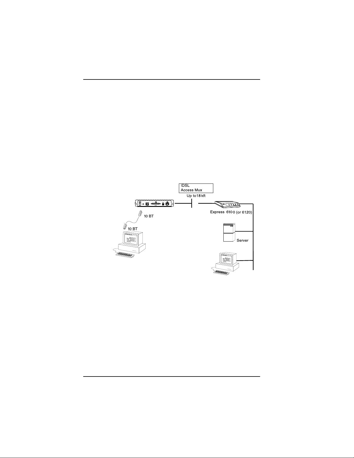
Single User to Corporate LAN (Figure 1-3)
• Telecommuter/Home Office Access to the corporate LAN
• Single device access
• User Datagram Protocol (UDP) broadcasts are “relayed” to
corporate LAN.
• Client device can obtain the Internet Protocol (IP) address
dynamicallyusing Dynamic Host Configuration Protocol
(DHCP).
• Compatible with popular central site LAN access devices
Figure 1-3. Single User to Corporate LAN
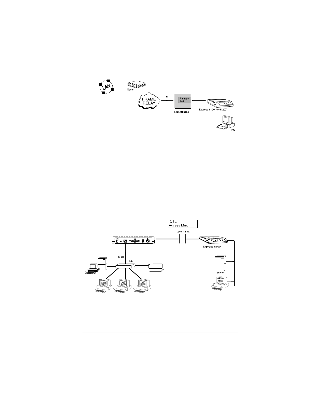
Frame Relay Connectivity to ADTRAN Frame Port 144 (Figure 1-4)
• Telecommuter/Home Office Access to the corporate LAN
• Access to any other router within the Frame Relay Network
• User Datagram Protocol (UDP) broadcasts are “relayed” to
corporate LAN.
• FramePort 144 provides concentration of up to 96 ID SL interfaces
into a single DS-1.
1-2 Express 6100/6120 User Manual 61200176L1-1
Page 25
Chapter 1. Understanding IDSL and the Express 6100/6120
IDSL
Figure 1-4. Frame Relay Connectivity to ADTRAN Frame Port 144
SmallOffice/Home Office(SOHO) to Corporate LAN (Figs 1-5 and
1-6)
• ConnectsthesmallofficeorhomeofficetothecorporateLAN
• Routes IP and Internet Packet Exchange (IPX) traffic from
multiple devices to the corporate LAN
• Bridges all non-routed traffic (e.g., AppleTalk)
• Low cost alternative to buying a high-end router
• Compatible with popular central site LAN access devices
Figure 1-5. SOHO to Corporate LAN (6100)
61200176L1-1 Express 6100/6120 User Manual 1-3
Page 26

Chapter 1. Understanding IDSL and the Express 6100/6120
18
Figure 1-6. SOHO to Corporate LAN (6120)
The Express 6100/612 0 provides the following basic functions:
1. LAN Bridge: Bridging provides a point-to-point connection
between two LANs. The bridge learning function scans the
source and destination media access control (MAC) addresses of
all packets on its local LAN and determines which packets
should be transmitted over the IDSL link. Applications include
connectivity between single user or small offices to corporate
LANs.
2. IP Router: T he Express 6100/6120 can function as an IP router
using the Routing Information Protocol(RIP) for advertising and
learning routes among other routers. Static routes may also be
entered into the routing table.
3. IPX Router: IPX routers and services can be exchanged between
the Express 6100/6120 and other devices using RIP and Service
Advertising Protocol (SAP). Watchdog serialization filtering and
spoofing can permit the ISDN to be idle during no application
traffic periods.
4. Network Address Translation (NAT):Single networks can con-
nect to the Internet with this function. The Express 6100/6120
translates outgoing IP packets over the IDSL to the IP router at
the Internet Service Provider. Many popular Internet applications are supported.
1-4 Express 6100/6120 User Manual 61200176L1-1
Page 27

Chapter 1. Understanding IDSL and the Express 6100/6120
5. PPP or Frame Relay: The layer two protocol used to transfer
packets can be PPP or Frame Relay (RFC 1490). PPP allows a
point-to-point connection, whereas Frame Relay can provide up
to ten permanent virtual circuits.
Routing and Bridging with the Express 6100/
6120
The Express 6100/6120 is a Router and Transparent Learning Bridge.
Its features can be easily configured and used once several basic concepts are understood.
Factory Default
The Express 6100/6120 comes from the factory configured for MAC
Bridging with no filters or connection information defined. An IP address of 10.0.0.1 with a network mask of 255.255.255.0 is preloaded.
The factory default layer two configuration is Auto Detect, which automatically detects PPP or Frame Relay.
Bridging
In Bridge Mode, the Express 6100/6120 can be used to connect two
LAN segments. In this mode, all protocols are supported because they
are transported across the IDSL link at the MAC layer. The Spanning
Tree Algorithm can be used to guarantee a loop-free topology. MAC
addresses are “learned” by each Express 6100/6120 to prevent nonWAN packets from being bridged.
IP Routing
The Express 6100/6120 operates as an IP router when the Configuration/IP/IP Router/Mode option is configuredto On.InPPPmode,the
Express 6100/6120 uses an IP unnumbered WAN interface; the IP address and mask assigned to the unit’s LAN interface apply to all routing and IP operations for the unit. In Frame Relay mode, each PVC
can be specified as numbered or unnumbered links. If a default gateway is specified on the network of the Ethernet interface, the unit attempts to reach the gateway through that interface. If no default
gateway is specified (i.e., 0.0.0.0) the WAN interface becomes the de-
61200176L1-1 Express 6100/6120 User Manual 1-5
Page 28

Chapter 1. Understanding IDSL and the Express 6100/6120
fault gateway (recommended for remote applications when there are
no other routers on the remote LAN).
IPX Routing
Network routes and services are learned and advertised using Novell’s RIP and SAP.
Concurrent Routing And Bridging
The Express 6100/6120 can route IP and IPX as well as bridge non-IP/
IPX packets simultaneously. The PPP profile will by default negotiate
PPP network protocols to support the transmission and reception of
IP, IPX, and Bridge packets. If the PPP peer does not accept a protocol,
theExpress6100/6120willfallback to any combinationof routingand
bridging.
Network Address Translation Mode
NAT is a special mode of operation in which the Express 6100/6120
obtains a dynamically assigned IP address from the peer router (typically an Internet Service Provider). This allows a network of computers to appear as a single IP address.
NAT is enabled if the layer-two protocol is PPP and the PPP profile
has the IP parameter NATset to Yes, orthe layer two protocolis Frame
Relay and a D LCI mapping has the IP Map/Nat parameter set t o Yes.
The network computer’s IP stack may use DHCP to request an IP address, default gateway address, and domain name server addresses
from the Express 6100/6120.
1-6 Express 6100/6120 User Manual 61200176L1-1
Page 29

Chapter 1. Understanding IDSL and the Express 6100/6120
Front Panel
Figure 1-7 shows the front panel of the Express 6100. The indicators
are divided into LAN functions, WAN functions, and Test functions.
6100
Express
Figure 1-7. Express 6100 Front Panel
Indicators
TX/RX Flashes when transmitting and receiving
data on the 10BaseT connector.
LI Link integrity. Illuminates when there is a
good connection between the Express
6100 and the Hub/NIC card.
PWR Flashes when the IDSL link (pins 4 and 5
on RJ-45) is not in sync. Solid when in
sync.
TEST 1, 2 Illuminates solid when either PPP or Frame
Relay has an active connection. Flashes
when trying to establish a PPP or Frame
Relay connection.
61200176L1-1 Express 6100/6120 User Manual 1-7
Page 30

Chapter 1. Understanding IDSL and the Express 6100/6120
Figure 1-8 shows the front panel of the Express 6120.
6
Figure 1-8. Express 6120 Front Panel
Indicators
TX/RX Flashes when transmitting and receiving
data on the 10BaseT connector.
1, 2, 3, 4 Link integrity. Illuminates when there is a
good connection between the Express
6120 and the Hub/NIC card.
PWR Flashes when the IDSL link (pins 4 and 5
on RJ-45) is not in sync. Solid when in
sync.
TEST 1, 2 Illuminates solid when either PPP or Frame
Relay has an active connection. Flashes
when trying to establish a PPP or Frame
Relay connection.
Rear Panel
The Express 6100/6120 has one RJ-45 jack, labeled ISDN, on the rear
panel for network connection (see Figure 1-9 on page 1-9 and Figure
1-10 on page 1-9).
The OFF/ON switch block is for factory default and firmware down-
loading. With switch 1 in the up or OFF position, the Express 6100/
6120 will immediately go into a download mode when power is enabled. Switch 1 must be in the down or ON position in order to boot
up normally. Switch 2 in the up or OFF position will force the entire
configuration to be factory defaulted.
1-8 Express 6100/6120 User Manual 61200176L1-1
Page 31

Chapter 1. Understanding IDSL and the Express 6100/6120
The Express 6100/6120 transfers data up to 144 kbps over a two-wire
facility. This type of service is a permanent connection between endpoints or between the unit and the Frame Relay cloud. It is sometimes
referred to as a leased connection, a dedicated connection, a “nailedup” connection, or a private circuit. Leas ed connection or leased line
is used in this manual to represent these types of services.
Figure 1-9. Express 6100 Rear Panel
Figure 1-10. Express 6120 Rear Panel
Configuration
The Express 6100/6120 is configured using a menu-based i nterface.
This interface can be accessed via the maintenance port using any
asynchronous VT 100 termi nal or personal computer running a terminal emulation program, or via IP using a Telnet client program or web
browser. To use the Telnet interface or web browser, the Express
6100/6120 must first have an IP address programmed into it via the
maintenance port. The factory default is 10.0.0.1.
61200176L1-1 Express 6100/6120 User Manual 1-9
Page 32

Chapter 1. Understanding IDSL and the Express 6100/6120
Security
Securityon network devices is a major concern foralmost anyone with
a network. The Express 6100/6120 provides many tools for securing
the local network from hostile users. Connections can be authenticated using passwords. A RADIUS client can also be used.
The Telnet and web browser configuration can also be protected using
the same authentication methods. Each menu item in the Express
6100/6120 has a security level associated with it. A Telnet session is
assigneda privilege levelwhich determines which menu items are accessible to the Telnet client. See Security Levels on page 3-7 for more
information on menu security levels.
Filters can be defined to prevent certain addresses or protocols from
being transferred from LAN-to-WAN, WAN-to-LAN, or WAN-toWAN.
As already mentioned, a web browser can be used to configure the Express 6100/6120. This is accomplished by entering http://10.0.0.1 on
anyWindowsInternetExplorer browser. If theExpress 6100/6120’sIP
address has been changed from the factory default, then 10.0.0.1
should be replaced by that address.
1-10 Express 6100/6120 User Manual 61200176L1-1
Page 33

Chapter 2
After unpacking the unit, immediately inspect it for possible shipping damage. If damage is discovered, file a claim immediately with
the shipping carrier; then contact the ADTRAN Repair and Return
department.
Installation
IDSL NETWORK CONNECTION
The Express 6100/6120 supports leased operation. A single RJ-49C
modular jack labeled ISDN o n the rear p anel provides connection to
the network. Leased operation mode supports dedicated 2B1Q data
service at rates up to 144 kbps by using a nailed up circuit, or a permanent connection between endpoints.
See Connector Pinouts on page D-1 for ISDN network connector pin
assignments.
6100 LOCAL AREA NETWORK CONNECTION
The Express 6100 has a single 10BaseT connection port that provides
half duplex 10 Mbps operation over a 4-wire twistedpair.Other types
of Ethernet interfaces (i.e., AUI, 10Base2, etc.) can be accommodated
by obtaining an appropriate converter.
6120 LOCAL AREA NETWORK CONNECTION
The Express 6120 has an integrated hub with four 10BaseT connection ports. Each port can provide half duplex 10 Mbps operation over
a 4-wire twisted pair. All four 10BaseT connection ports are the same
and are treated equally by the Express 6120.
To connect to an NIC you will need a straight-through cable.To connect to another hub you will need an Ethernet crossover cable, unless
the hub you are connecting to has a crossover switch. See Connector
Pinouts on page D-1 for 10BaseT connector pin assignments.
61200176L1-1 Express 6100/6120 User Manual 2-1
Page 34

Chapter 2. Installation
2-2 Express 6100/6120 User Manual 61200176L1-1
Page 35

Chapter 3
Terminal Menu Operation
and Structure
TERMINAL MENU STRUCTURE
The Express 6100/6120 uses a multilevel menu s tructure containing
both menu items and data fields. All menu operations and data displayin the terminal menu window. The Express6100/6120 is shipped
in the Factory Default configuration. Connect any VT 100 or VT 220
type terminal emulator to the maintenance port. The default rate is
9600 baud 8-N-1. The terminal emulator can flow the Express 6100/
6120 off using software flow control. Hardware flow control is not
used.
The opening menu (the Main menu, or top-level menu) is the access
point to all other operations. Each Main menu item has several functions and submenus to identify and access specific parameters. Figure
3-1onpage3-3showsthetop-levelterminalmenu.
To edit items in the terminal menus, you must have the
appropriate security level. Each menu description in this
section indicates the required security level required for
writeaccess.Themaintenanceportisalwaysatsecurity
level 0, giving full access to all configuration items.
61200176L1-1 Express 6100/6120 User Manual 3-1
Page 36

Chapter 3. Terminal Menu Operation and Structure
The Main menu contains the following options.
CONFIGURATION
>
The Configuration menu provides options to set up the operational
configurationfor the Express 6100/6120. See t he section Configuration
Menu on page 3-8 for detailed information on the available options.
STATUS
>
The Status menu provides options to review and monitor the status
of the Express 6100/6120 system. See the section Status Menu on page
3-57 for detailed information on the available options.
TEST
>
The Test menu can be used for performing diagnostic testing of the
Express6100/6120.See the sectionTest Menu on page 3-68 fordetailed
information on the tests available.
LOGS
>
The Logs menu can be used for viewing the operational logs for the
Express 6100/6120. See the section Logs Menu on page 3-69 for detailed information on the available options.
UTILITIES
>
The Utilities menu provides tools for system diagnostics and upgrading the Express 6100/6120. See the section Utilities Menu on page 3-73
for detailed information on the available options.
3-2 Express 6100/6120 User Manual 61200176L1-1
Page 37

Chapter 3. Terminal Menu Operation and Structure
1
2
3
4
1 MenuPath Describes the current position in the terminal
menu structure.
2 RightPane Lists available submenus. Additional sub-
menusavailablethroughthispaneareindicated by the [+] and [DATA] symbols.
3LeftPane Lists available menus.
4Mode Describes current operating mode.
5 Loop Status Displays current status of IDSL line.
6 Rate Status Displays current rate of connection.
7 Navigation
Help
Displays list of characters you can use to navigate the terminal menus (press Control-Z).
5
6
7
Figure 3-1. Top Level Terminal Menu
61200176L1-1 Express 6100/6120 User Manual 3-3
Page 38

Chapter 3. Terminal Menu Operation and Structure
NAVIGATING THE TERMINAL MENUS
The following sections provide information on how to navigate
through the terminal menus.
General Layout
When you first start a terminal mode session, the screen shown in Figure 3-1 on page 3-3 displays. The screen is divided into left and right
panes. Theleftpaneshowsthecurrentlistofsubmenus,whilethe
rightpaneshowsthecontentsofaselectedsubmenu.
Menu Path
The top line of the display shows this session’s current position (path)
in the menutree. Figure 3-1 on page 3-3 showsthe top menu levelwith
the cursor on the Configurationsubmenu, so the path display shows
Express 6100/Configuration.
Moving Around
Press
to the right pane. Press
from the right pane back to the left pane. Use the up and down arrows
to move around within each pane. Press
Press the left arrow key or the
following options display throughout the menus.
Submenus [+] or [DATA]
Menus that display [+] or [DATA] indicate that more items are avail-
able when selected.
Activation Field <+>
Menus that display <+> indicate that an action is to be taken, such as
activating a test.
3-4 Express 6100/6120 User Manual 61200176L1-1
or the right arrow key to move the cursor from the left pane
Tab
or the left arrow key to move the cursor
Tab
to activate a menu.
Enter
Escape
keytogobackupthemenu.The
Page 39

Chapter 3. Terminal Menu Operation and Structure
Editable Data Field
A highlighted menu item indicates that you can enter data in that
field.
Read-Only Field
An underlinedfield is a display field that contains read-only information.
Navigation with the Keyboard
You can use different keystrokes to navigate through the terminal
menu. Press
Control-Z
to activate a pop-up screen with the available
keystrokes. The following section provides a list of the available keystrokes and the results:
General Navigation
H
J
Returns to the home screen.
Jumps between two menu items. Press J while on a
menu item of interest, and you will jump back to the
main screen. Go to another menu item of interest, Press
J, and you will jump back to the screen that was
displayed the first time you pressed
J.PressJ anytime
you want to jump between these items.
Arrow Keys
Selects items and moves between the left and right
panes. The left arrow key allows you to go back up the
menu.
Enter
Escape
Activates an item or moves into submenu.
Cancels an edit. Allows you to go back up the menu.
Also will dismiss the pop-up help screens.
Tab
A
Z
Backspace
Moves between the left and right panes.
Moves to the top of a screen.
Moves to the bottom of a screen.
Ascends one menu level.
61200176L1-1 Express 6100/6120 User Manual 3-5
Page 40

Chapter 3. Terminal Menu Operation and Structure
Session Management
Control-L
Control-S
Logs out of the session.
Invalidates the password entry and returns to the login
screen. The Password prompt will display.
Control-R
Refreshes the screen. To save time, only the portion of the
screen that has changed is refreshed. This option should
be necessary only if the display picks up incorrect
characters.
Configuration
F
Restores factory default settings. This setting restores the factory
defaults based on the location of the cursor. Entire submenus can
be factory defaulted.
C
Copies selected items to the clipboard. The amount of
information you can copy depends on the cursor location when
you press
C. For example, if the cursor is over an editable field,
only that item is copied. If the cursor is over the index number of
a list, then all of the items in the row of the list are copied. For
example, if the cursor is over the Num field in the Frame Relay
Mapping screen, all of the information associated with the Map
entry is copied.
P
Pastes the item stored in the clipboard, if the information in
compatible. You must confirm all pastes except those to a single
editable field.
>
For certain types of fields, when you paste information into the
field, the value increments by 1.
<
For certain types of fields, when you paste information into the
field, the value decrements by 1.
I
Inserts a new item in a list. For example, add a new item to the
Connection List by pressing
I while the cursor is over the index
number.
D
Deletes a list item. For example, delete an item from the
Connection List by pressing
D while the index number is active.
3-6 Express 6100/6120 User Manual 61200176L1-1
Page 41

Chapter 3. Terminal Menu Operation and Structure
Security Levels
Each menu item on the configuration screens has an associated security level. The security level ranges from 0 (highest security level) to 5
(lowest security level). This level determines whether a Telnet session
can access that menu item. The Telnet session is assigned a security
level set by the user. Passwords can only be accessed as security level
0. The maintenance port is always at security level 0.
The security levels are assigned as fol lows:
Level
0 Access all parameters including passwords
1 Access all parameters except passwords
2 Access all parameters except passwords and
authentication methods
3 Access all parameters except passwords, authentication
methods, and IDSL parameters
4 Access only test and status menus
5 Access status menus only
61200176L1-1 Express 6100/6120 User Manual 3-7
Page 42

Chapter 3. Terminal Menu Operation and Structure
>
CONFIGURATION MENU
» System Info
The System Info menu provides basic information about the unit and
displays data fields for editing information. Figure 3-2 displays the
submenus available under this menu item.
Figure 3-2. Configuration/System Info Screen
»» System Name
Write security: 3; Read security: 5
Provides a user-configurable text string for the name of the Express
6100/6120. This name can help distinguish between different installations. You can enter up to 31 alpha-numeric characters in this field,
including spaces and special characters (such as an under bar). The
system name is also used for PPP authentication and IPX service
name.
»» System Location
Write security: 3; Read security: 5
Provides a user-configurable text string for the location of the Express
6100/6120. Thishelps to keep trackof the physical location of theunit.
3-8 Express 6100/6120 User Manual 61200176L1-1
Page 43

Chapter 3. Terminal Menu Operation and Structure
You can enter up to 31 alpha-numeric characters in this field, including spaces and special characters (such as an under bar).
»» System Contact
Write security: 3; Read security: 5
Provides a user-configurable text string for the contact name. This
field can contain a name, phone number, or e-mail address of a person
responsible for the Express 6100/6120. You can enter up to 31 alphanumeric characters in this field, including spaces and special characters (such as an under bar).
»» Firmware Revision
Read security: 5
Displaysthecurrentfirmwarerevision level of t he Express6100/6120.
This field is a read-only field.
»» System Uptime
Read security: 5
Displays the length of time the Express 6100/6120 has been running
since power up or reset. This field is a read-only field.
61200176L1-1 Express 6100/6120 User Manual 3-9
Page 44

Chapter 3. Terminal Menu Operation and Structure
» Configuration/WAN
The WAN menu is used to set up the ISDN parameters for the Express
6100/6120. Figure 3-3 shows the WAN menu.
Figure 3-3. Configuration/WAN Screen
»» WAN/ISDN
Write security: 2; Read security: 5
Selects the mode the IDSL line is in.
ISDN/Clock Mode
Write security: 2; Read security: 5
The Express 6100/6120 can only operate as a slave.
3-10 Express 6100/6120 User Manual 61200176L1-1
Page 45

Chapter 3. Terminal Menu Operation and Structure
IDSL/Channel Rate
Write security: 2; Read security: 5
Determines the rate at which data is transferred over the IDSL link.
Possible rates are 64K, 128K, and 144K.
IDSL/NEBEs
Read security: 5
This contains the number of Near-End-Block-Errors (NEBEs) that
have been detected by the Express 6100/6120’s IDSL circuitry. Continuous errors can indicate a line problem, but a burst at one time is
normal.
IDSL/FEBEs
Read security: 5
This contains the number of Far-End-Block-Errors (FEBEs) that have
been detected by the IDSL circuitry on the other end of the link. Continuous errors can indicate a line problem, but a burst at one time is
normal.
»» WAN/L2 Protocol
Write security: 3, Read security: 5
This parameter specifies the layer 2 data link layer transport used.
When selected as PPP, the Express6100/6120 will negotiate PPP over
the IDSL interface. T his is used mainly for campus wiring applications. Parameters for controlling the PPP negotiation are in the Con-
figuration/PPP Profile menu. Frame Relay should be selected when
the Express 6100/6120 is connected to a Frame Relay switch. The
Configuration/WAN/Frame Relay menu is used for controlling the
Frame Relay parameters. When
Auto Detect
(def) is selected, the Express 6100/6120 will look at the incoming packets in order to determine what layer 2 protocolto use.
61200176L1-1 Express 6100/6120 User Manual 3-11
Page 46

Chapter 3. Terminal Menu Operation and Structure
» Configuration/IP
The IP menu is used to set up the IP parameters for the Express 6100/
6120. Any general IP-related configuration item is under this menu.
Figure 3-4 shows the IP menu.
Figure 3-4. Configuration/IP Screen
»» IP/IP Address
Write security: 2; Read security: 5
TheIPaddress assigned to t he Express6100/6120’sEthernetportis set
here. This address must be unique within the network. Factory default is 10.0.0.1.
»» IP/Subnet Mask
Write security: 2; Read security: 5
The IP network mask t o be applied to the Express 6100/6120’s Ethernet port is set here. Factory default is 255.255.255.0.
3-12 Express 6100/6120 User Manual 61200176L1-1
Page 47

Chapter 3. Terminal Menu Operation and Structure
»» IP/Default Gateway
Write security: 3; Read security: 5
The default gateway is used by the Express 6100/6120 for sending IP
packetswhosedestinationaddressisnotfoundintheroutetable. If
this address is all zeros, then the first WAN connection becomes the
default gateway.
»» IP/Static Routes
Static Routes can be inserted under this menu.
Static Routes/Active
Write security: 4; Read security: 5
Adds this static route entry to the IP routing table when set to Yes
(def) and removes it (if it was previously added) if set to No.
Static Routes/IP Address
Write security: 4; Read security: 5
This is the IP address of the host or network address of the device being routed to.
Static Routes/Subnet Mask
Write security: 4; Read security: 5
Thismask determines thebitsin the previousIP address thatareused.
If this is to be a host route, it must be set to all ones (255.255.255.255).
Static Routes/Gateway
Write security: 4; Read security: 5
This is the IP address of the router to receive the forwarded IP packet.
Static Routes/Hops
Write security: 4; Read security: 5
This is the number of router hops requiredto get to the network or
host. Maximum distance is 15 hops.
61200176L1-1 Express 6100/6120 User Manual 3-13
Page 48

Chapter 3. Terminal Menu Operation and Structure
Static Routes/Private
Write security: 4; Read security: 5
When set to No, the Express 6100/6120 will advertise this static route
using RIP. Otherwise, setting to Yes means that the route is kept private.
»» IP/IP Router
The IP router is configured under this menu as follows.
IP Router/Mode
Write security: 3; Read security: 5
When this option is set to On, the Express 6100/6120 will advertise
and listen to routes from other IP routers. If Off (def), the route table
is still used but only static routes are used for routing IP packets and
only the Ethernet port is used. IP packets can be sent over the WAN,
but only when bridged.
IP/RIP
Write security: 3; Read security: 5
The Routing Information Protocol (RIP) is supported by the Express
6100/6120. The following parameters are required for setting up the
mode on the Ethernet port:
RIP/Mode
Write security: 3; Read security: 5
This option turns RIP On or Off (def).
RIP/Protocol
Write security: 3; Read security: 5
Version can be V1 (def) or V2.
3-14 Express 6100/6120 User Manual 61200176L1-1
Page 49

Chapter 3. Terminal Menu Operation and Structure
RIP/Method
Write security: 3; Read security: 5
Split Horizon Only routes not learned on the Ethernet port
are advertised.
Poison Reverse
(def)
All routes are advertised, including routes
learned from the Ethernet port. These routes
are poisoned.
None All routes are advertised, including routes
learnedfrom the Ethernet port. N o attempt is
made to poison these routes.
RIP/Direction
Write security: 3; Read security: 5
Tx and Rx (def) RIP advertisements are transmitted and lis-
tened to on the Ethernet port.
Tx only RIP advertisements are transmitted and not
listened to.
Rx only RIP advertisements are listened to but not
transmitted.
RIP/V2 Secret
Write security: 0; Read security: 0
This is a text string used to authenticate advertised routes.
»» IP/NAT
The Network Address Translation general parameters are set up under this menu.
NAT/DHCP Mode
Write security: 3; Read security: 5
When this option is set to On, the Express 6100/6120 acts as a DHCP
server and will dynamically assign IP, network mask, default gateway, and DNS addresses to any device which transmits a broadcast
DHCP request. The addresses assigned are based on the Express
6100/6120’s own IP address and will be within the same network.
61200176L1-1 Express 6100/6120 User Manual 3-15
Page 50

Chapter 3. Terminal Menu Operation and Structure
This mode is most commonly used with the NAT functionality. The
default is Off.
NAT/DHCP Renewal Time
Write security: 3; Read security: 5
This is the number of hours that the DHCP server should allow the device before it is required to send a new DHCP request. The default is
15 hours, and 0 represents an infinite lease.
NAT/Web Server
Write security: 3; Read security: 5
This is the IP address of a web server on the Ethernet network. When
anactiveNATconnectionismadetotheInternet,anyHTTP,FTP,or
SMTP server requests from the WAN are translated and sent to this
web server. Normally, communication across NAT must be initiated
from the LAN side of the Express 6100/6120. Web Server allows a single machine on the NAT side to be accessed from the Internet side of
NAT. This provides outside access to a web server, mail, or ftp server.
NAT/Default IP
This is the IP address used by the Express 6100/6120 for NetworkAddress Translation when nothing is assigned during the PPP negotiation when PPP mode is active or when nothing isspecified in the DLCI
Mapping’s Link IP Address.
»» IP/DNS
The Domain Name Server parameters used by the Express 6100/6120
are specified here. The DNS server addresses can be exchanged between PPP peers. When a conne ction occurs and IPCP is n egotiated,
theExpress 6100/6120 will get theDNS server addressesfromthe PPP
peer. If the configured DNS server addresses (Server 1 and Server 2)
areallzeros,theaddressesfromthePPPpeerareused.InNATmode,
the PPP peer’s DNS addresses are always used. TheDNSaddressesset
in Server 1 and Server 2 are offered to a PPP peer if requested.
3-16 Express 6100/6120 User Manual 61200176L1-1
Page 51

Chapter 3. Terminal Menu Operation and Structure
DNS/Domain Name
Write security: 3; Read security: 5
Thisis a text string used to represent the domain nameused by the Express 6100/6120.
DNS/Server 1
Write security: 3; Read security: 5
This is the IP address for the primary DNS device. It is the first server
that domain name requests are sent.
DNS/Server 2
Write security: 3; Read security: 5
This is the IP address for the secondary DNS device. It is used as a
back-up in case the primary address does not respond to the request.
»» IP/UDP Relay
The Express 6100/6120 can be configured as a relay agent for UDP
broadcast packets. Normally, a router will not forward UDP broadcast packets. However, many network applications use UDP broadcasts to configure addresses,host names, and other information. If
hosts using these protocols are not on the same network segment as
the servers providing the information, the client programs will not receive a response without enabling the UDP relay agent.
UDP Relay/Mode
Write security: 3; Read security: 5
When this option is set to On (def), the Express 6100/6120 will act as
a relay agent.
UDP Relay/UDP Relay List
Up to four relay destination servers can be specified in this list.
61200176L1-1 Express 6100/6120 User Manual 3-17
Page 52

Chapter 3. Terminal Menu Operation and Structure
UDP Relay List/Relay Address
Write security: 3; Read security: 5
This is the IP address of the server that will receive the relay packet.
UDP Relay List/UDP Port Type
Write security: 3; Read security: 5
Standard
(def)
The following standard UDP protocols are relayed
when set: DHCP, TFTP, DNS, NTP (Network Time
Protocol, port 123). NBNS (NetBIOS Name Server,
port137),NBDG (NetBIOS Datagram,port 138), and
BootP.
Specified When set, the UDP port (1 to 65535) can be specified
intheUDP Portcolumns.(upto a maximum of three
per server)
UDP Relay List/UDP Ports 1, 2, and 3
Write security: 3; Read security: 5
UDP Port 1, UDP Port 2, and UDP Port 3 are used for specifying UDP
ports to be relayed. These fields only apply when UDP Port Typeis
set to Specified.
»» IP/Proxy ARP
Write security: 4; Read security: 5
This feature allows the network portion of a group of addresses to be
shared among several physical network segments. The ARP protocol
itselfprovides a way fordevices to create a mapping between physical
(i.e., Ethernet) addresses and logical IP addresses. Proxy ARP makes
use of this mapping feature by instructing a router to answer ARP requests as a “proxy ” for the IP addresses behind one of its ports. The
device which sent the ARP request will then correctly assume that it
can reach the requested IP address by sending packets to the physical
address that was returned to it. This technique effectively hides the
fact that a network has been (further) subnetted. If this option is set to
Yes (def), when an ARP request is received on the Ethernet port the
address is looked up in the IP routing table. If the forwarding port is
not on the Ethernet port and the route is not the default route, the Express 6100/6120 will answer the request with its own hardware ad-
3-18 Express 6100/6120 User Manual 61200176L1-1
Page 53

Chapter 3. Terminal Menu Operation and Structure
dress. If set to No, the Express 6100/6120 will only respond to ARP
requests received for its own IP address.
» Configuration/IPX
The IPX menu is used to set up the IPX parameters for the Express
6100/6120. Any general IPX-related configuration item can be found
under this menu. Figure 3-5 shows the IPX menu.
Figure 3-5. Configuration/IPX Screen
»» IPX/Mode
Write security: 2; Read security: 5
When this option is set to On, the Express 6100/6120 will route IPX.
Setting it to Off (def) will disable all IPX functionality.
»» IPX/Network
Write security: 2; Read security: 5
TheIPX networkaddress forthe Ethernetport is set here. This isan eight-digit
hexadecimal value that uniquely identifies the network segment of the Ethernet port. Accidental selection of an IPX network which is already in use on another network segment may cause hard-to-diagnose problems. IPX network
numbers should be carefully tracked.
61200176L1-1 Express 6100/6120 User Manual 3-19
Page 54

Chapter 3. Terminal Menu Operation and Structure
»» IPX/Frame Type
Write security: 2; Read security: 5
TheExpress 6100/6120 supports allfour defined IPX frametypes. The
possible frame types are: Ether Type II (def), Ether 802.3 (Raw),or
Ether SNAP (802.2 SNAP). Only one frame type can be used at one
time.
»» IPX/Seed Status
Write security: 2; Read security: 5
The seed status defines what the Express 6100/6120 is to do with the
network informationon the selected frame type during startup. There
are three possible seeding selections specified:
Seed The Express 6100/6120 will listen for an IPX
network number being sent by another router
(including Novell software routers residing on
servers) on the Ethernet segment connected to
this port and use this number if it exists. If it
does not discover a number in use, the Express
6100/6120 will use the configured IPX network
number for the Ethernet segment.
Non-Seed
(def)
The Express 6100/6120 will listen for an I PX
network number being sent by another router
(including Novell software routers residing on
servers) on the Ethernet segment connected to
this port and use this number if it exists. If it
does not discover a number in use, the Express
6100/6120 will wait indefinitely until a number
is sent by another router on the Ethernet segment.
3-20 Express 6100/6120 User Manual 61200176L1-1
Page 55

Chapter 3. Terminal Menu Operation and Structure
AutoSeed
The Express 6100/6120 will listen for an I PX
network number being sent by another router
(including Novell software routers residing on
servers) on the Ethernet segment connected to
this port and use this number if it exists. If it
does not discover a number in use, the Express
6100/6120 will auto-generate a valid number
using its routing tables.
»» IPX/RIP Timer
Write security: 3; Read security: 5
This value specifies how often the Express 6100/6120 sends out IPX
RIP packets on the network segment attached to the Ethernet port.
The RIP packets sent contain routing information about the networks
for which this Express 6100/6120 is responsible. The default value is
60 seconds.
»» IPX/SAP Timer
Write security: 3; Read security: 5
This value specifies how often the Express 6100/6120 sends out IPX
SAP (Service Access Protocol) packets on the network segment attached to the Ethernet port. The SAP packets sent contain information
about the services (such as servers, printers, etc.) for which this Express 6100/6120 is responsible. The default value is 60 seconds.
» Configuration/Bridge
TheBridgemenuisusedtosetupthebridgeparametersfortheExpress 6100/6120. The bridging function runs at the Media Access
Control (MAC) level which allows any protocol packets that run over
Ethernet to be forwarded. Bridging can run concurrently with the IP
and IPX routing. However, certain rules apply for when packets are
bridged across a WAN con nection. When IP routing is active, IP packets (which include ARP packets) are not bridged. When IPX routing
is active, IPX packets are not bridged. Also, the WAN IP Bridge and
WAN IPX Bridge menus allow the WAN connection to bridge packets
to the Express 6100/6120 but get routed as soon as they arrive at the
unit. Figure 3-6 shows the Bridge menu.
61200176L1-1 Express 6100/6120 User Manual 3-21
Page 56

Chapter 3. Terminal Menu Operation and Structure
Figure 3-6. Configuration/Bridge Screen
»» Bridge/Mode
Write security: 2; Read security: 5
When this option is set to On (def), the Express6100/6120 bridge function will be enabled. Setting it to Off will disable all bridge functionality.
»» Bridge/WAN IP Bridge
When IP routing is active, the Express 6100/6120 will allow another
WAN device to bridgeIP packetsto it usingPPP BCP. Normally,two
IP routers would negotiate PPP IPCP to exchange IP packets. However, if a device can only support PPP BCP, IP packets are encapsulated
by the device as bridge packets. The Express 6100/6120 can treat the
WANIPBridgeasavirtualEthernetportconnectedonlytoaWAN
device which has negotiated PPP BCP. This menu allows the IP parameters for this virtual Ethernet to be set up.
WAN IP Bridge/Network
Write security: 2; Read security: 5
This is the IP address of the virtual Ethernet port.
3-22 Express 6100/6120 User Manual 61200176L1-1
Page 57

Chapter 3. Terminal Menu Operation and Structure
WAN IP Bridge/Netmask
Write security: 2; Read security: 5
This is the network mask to be applied to the virtual Ethernet port.
WAN IP Bridge/Triggered
Write security: 2; Read security: 5
When set to Yes, only IP RIP updates are sent when the routing table
has changed. When set to No (def), updates are sent periodically.
RIP version, method, and direction are determined by the
Ethernet parameters set in the Configuration/IP/IP
Router/RIP menu.
WAN IP Bridge/Proxy ARP
If this option is set to Yes (def), the Express6100/6120 will proxy ARP
on the bridge IP port. See the section IP/Proxy ARP on page 3-18 for an
explanation of the proxy ARP function.
»» Bridge/WAN IPX Bridge
When IPX routing is active, the Express 6100/6120will allow another
WAN device to bridge IPX packets to it using PPP BCP. Normally,
twoIPXrouterswouldnegotiatePPP IPXCP to exchangeIPX packets.
However, if a device can only support PPP BCP, IPX packets are encapsulated by the device as bridge packets. The Express 6100/6120
can treat the WAN IPX Bridge as a virtual Ethernet port connected
only to a WAN device which has negotiated PPP BCP. This menu allows the IPX parameters for this virtual Ethernet to be set up.
WAN IPX Bridge/Network
Write security: 2; Read security: 5
This is the network address of the virtual Ethernet port. See IPX/Net-
work on page 3-19 for an explanation of the IPX network number.
61200176L1-1 Express 6100/6120 User Manual 3-23
Page 58

Chapter 3. Terminal Menu Operation and Structure
WAN IPX Bridge/Frame Type
Write security: 2; Read security: 5
This is the frame type used for the virtual Ethernet port. See IPX/
Frame Type on page 3-20 for an explanation of the IPX frame type.
WAN IPX Bridge/Seed Status
Write security: 2; Read security: 5
This is the seed status used for the virtual Ethernet port. See IPX/Seed
Status on page 3-20 menu for an explanation of the IPX seed status.
WAN IPX Bridge/Triggered
Write security: 2; Read security: 5
When set to Yes, only IPX RIP and SAP updates are sent when the
routing or service table has changed. When set to No (def), updates
are sent periodically.
RIP and SAP periodic rates set for the Ethernet port (see IPX/
RIP Timer on page 3-21 and IPX/SAP Timer on page 3-21) are
used for the WAN IPX bridge port.
3-24 Express 6100/6120 User Manual 61200176L1-1
Page 59

Chapter 3. Terminal Menu Operation and Structure
» Configuration/Security
The Security menu is used to set up the authentication parameters
needed to authenticate PPP connection. Also, the filter defines are
placed under this menu. Figure 3-7 shows the Security menu.
Figure 3-7. Configuration/Security Screen
»» Security/Authentication
Write security: 1; Read security: 2
The method used for authenticating the PPP peer is selected here. The
possible values are:
None (def) No attempt is made to authenticate the PPP peer.
Radius The Express 6100/6120 will act as a RADIUS cli-
ent and authenticate the PPP peer using the RADIUS server. The Radius server parameters must
be set up properly for this to work.
PPP Profile The PPP profile is used to authenticate the PPP
peer.
See Configuration/PPP Profile on page 3-42 for moreinformationon authenticating.
61200176L1-1 Express 6100/6120 User Manual 3-25
Page 60

Chapter 3. Terminal Menu Operation and Structure
»» Security/Radius Server
The parameters for the radius server are configured in this menu. The
RADIUS server can be used for authenticating a PPP peer (if defined
under Security/Authentication) and for Telnet server sessions.
Radius Server/Primary Server
Write security: 1; Read security: 2
This is the IP address of the first RADIUS server that the Express
6100/6120 should attemptto communicatewith when authenticating
a PPP peer.
Radius Server/Secondary Server
Write security: 1; Read security: 2
This is the IP address of the back-up RADIUS server that the Express
6100/6120 should attempt to communicate with when the primary
server does not respond.
Radius Server/UDP Port
Write security: 1; Read security: 2
This is the UDP port that the Express 6100/6120 should use when
communicating with the RADIUS server. The default is 1645, which
is the commonly used port.
Radius Server/Secret
Write security: 0; Read security: 1
The RADIUS server and Express 6100/6120 share this text string,
which is used by the RADIUS sever to authenticate the Express 6100/
6120 that is the RADIUS client. The factory default is not to use a secret.
Radius Server/Retry Count
Write security: 1; Read security: 2
This is the number of times the Express 6100/6120 should send a request
packet to the RADIUS server without a response before giving up. If the
3-26 Express 6100/6120 User Manual 61200176L1-1
Page 61

Chapter 3. Terminal Menu Operation and Structure
number of attempts to communicate with the primary server is equal to
the retry count, the secondary server (if defined) is tried. If the secondary
server does not respond within the retry count, the PPP peer (or Telnet
session) is not authenticatedand is dropped. The default is 5.
»» Security/PPP
Write security: 1; Read security: 2
The PPP peer can be authenticated using three standard methods:
PAP (Password Authentication Protocol), CHAP (Challenge Handshake Protocol) and EAP (Extensible Authentication Protocol). The
strengthof the authentication is determinedin the order EAP, CHAP,
followed by PAP, where EAP is the strongest and PAP is the weakest.
PAP is a clear-text protocol, which means it is sent over the PPP link
in a readableformat. Caremust be takennot to allow highly sensitive
passwords to become compromised using this method. CHAP and
EAP use a one-way hashing algorithm which makes it virtually impossible to determine the password. EAP has other capabilities which
allow more flexibility than CHAP.
The following selections are possible:
PAP, CHAP or
EAP (def)
The Express 6100/6120 will ask for EAP during
thefirstPPPLCP negotiationandallowthePPP
peer to negotiate down to CHAP or PAP.
CHAP or EAP TheExpress 6100/6120 will ask for EAP during
thefirstPPPLCP negotiationandallowthePPP
peer to negotiate down to CHAP but not PAP.
EAP TheExpress 6100/6120 will only allow EAP to be
negotiated. If the PPP peer is not capable of doing
EAP, then the connection will not succeed.
»» Security/Filter Defines
The Express 6100/6120 can filter packets based on certain parameters
within the packet. The method used by the Express 6100/6120 allows
the highest flexibility for defining filters and assigning them to a profile. The filters are set up in two steps: (1) defini ng the packet types,
and (2) adding them to a list under the PPP profile or DLCI map. See
61200176L1-1 Express 6100/6120 User Manual 3-27
Page 62

Chapter 3. Terminal Menu Operation and Structure
the section DLCI Mapping/Filters on page 3-39 for examples of how to
set up filter profiles. This menu is used to define the individual filter
defines based on packet type.
Filter Defines /MAC Filter Defines
Write security: 2; Read security: 3
The MAC filter is applied to bridge packets only. Bridge packets
which are forwarded by the bridge functionality of the Express 6100/
6120 are defined here. Up to 32 MAC defines can be specified.
Name Identifies the filter entry
Src Addr 48-bit MAC source address used for comparison.
(hexadecimal format)
Src Mask Bits in the MAC source address which are com-
pared. (hexadecimal format)
Dest Addr 48-bit MAC destination address used for compari-
son. (hexadecimal format)
Dest Mask Bits in the MAC destination address used for com-
parison. (hexadecimal format)
MAC Type 16-bit MAC type field used for comparison. (hexa-
decimal format)
Type Msk Bits in the MAC type field used for comparison.
(hexadecimal format)
Filter Defines /Pattern Filter Defines
Write security: 2; Read security: 3
Thepattern filter is applied to bridge packets only. Thatis, any packet
whichisforwardedbythebridgefunctionalityoftheExpress6100/
6120. Up to 32 pattern defines can be specified.
Name Identifies the filter entry
Offset Offset from beginning of packet of where to start the
pattern comparison
Pattern 64 bits used for comparison. (hexadecimal format)
Mask Bits in the pattern to be compared. (hexadecimal format)
3-28 Express 6100/6120 User Manual 61200176L1-1
Page 63

Chapter 3. Terminal Menu Operation and Structure
Filter Defines /IP Filter Defines
Write security: 2; Read security: 3
The IP filter defines apply to any IP packet, whether it is routed or
bridged. Up to 32 IP defines can be specified.
Name Identifies the filter entry
IP Src IPaddress compared to the source address.
(dotted decimal format)
Src Mask Bits which are used in the source comparison.
(dotted decimal format)
IP Dest IP address compared to the destination ad-
dress. (dotted decimal format)
Dest Mask Bitswhich are used in the destination compar-
ison. (dotted decimal format)
Src Port IP source port number used for compariso n
Range: 0 to 65535. (decimal format)
Src Port Cmpr Type of comparison that is performed
=
not =
>
<
None
means ports equal to
means port not equal to
means port greater than
meansportlessthan
means the source port is not compared
Dst Port IP destination port number used for compari-
son Range: 0 to 65535. (decimal format)
DstPortCmpr Type of comparison that is performed
=
not =
>
<
None
61200176L1-1 Express 6100/6120 User Manual 3-29
means ports equal to
means port not equal to
means port greater than
meansportlessthan
means the destination port is not compared
Page 64

Chapter 3. Terminal Menu Operation and Structure
Proto Protocol used for comparison. Range: 0 to
255. (decimal format)
Proto Cmpr Type of comparison that is performed
=
not =
>
<
None
means protocols equal to
means protocols not equal to
means protocols greater than
means protocols less than
means the protocol is not compared
TCP Est
Yes
No
Ignore
only when TCP established
only when TCP not established
ignore TCP flags
Filter Defines /IPX Filter Defines
Write security: 2; Read security: 3
The IPX filter defines apply to any IPX packet whether it is routed or
bridged. Also, any IPX encapsulation type will be accounted for. Up
to 32 IPX defines can be specified.
Name Identifies the filter entry (15 characters
max)
Src Net 32-bit source network address
Src Mask Bits in the source network address which
are compared. (hexadecimal format)
Dest Net 32-bit destination network address
Dest Mask Bits in the destination network address
which are compared. (hexadecimal format)
Src Socket 16-bitvaluewhichisthesourcesocket.
Range: 0-65535.
3-30 Express 6100/6120 User Manual 61200176L1-1
Page 65

Chapter 3. Terminal Menu Operation and Structure
Src Socket Comp Type of comparison that is performed:
=
Not =
>
<
None
means socket equal to
means socket not equal to
means socket greater than
means socket less than
no comparison is done on source socket
Dest Socket 16-bit value which is the destination sock-
et.
Range: 0-65535.
Dest Socket
Type of comparison that is performed:
Comp
=
Not =
>
<
None
means socket equal to
means socket not equal to
means socket greater than
means socket less than
no comparison is done on destination
socket
Type 8-bit value which is the IPX type
Type Comp Type of comparison that is performed:
=
Not =
>
<
None
61200176L1-1 Express 6100/6120 User Manual 3-31
means type equal to
means type not equal to
means type greater than
means type less than
no comparison is done on IPX type
Page 66

Chapter 3. Terminal Menu Operation and Structure
» Configuration/Frame Relay
Frame Relay is a connection-oriented service requiring circuits to be
configured by your carrier to establish a physical link between two or
more locations. Multiple virtual circuits (which appear as virtual
point-to-point links) can be run through the same physical connection.
There are two types of virtual circuits supported in Frame Relay: Permanent Virtual Circuits (PVC) and Switched Virtual Circuit (SVC).
PVCs are like dedicated point-to-point private lines. Since the physical connection is always there in the form of a leased line, call setup
andtear down is done by a carriervia a network management system.
SVCs require setup and tear down and are generally not available
fromFrame Relay carriers. Virtually all FrameRelay communications
is done using PVCs. The Express 6100/6120 supports PVCs only.
Anumber calledthe Data Link Connection Identifier (DLCI) identifies
each virtual circuit within a shared physical channel.
Figure 3-8 shows the Frame Relay menu.
Figure 3-8. Configuration/Frame Relay Screen
3-32 Express 6100/6120 User Manual 61200176L1-1
Page 67

Chapter 3. Terminal Menu Operation and Structure
»» Frame Relay/Maintenance Protocol
Write security: 3, Read security: 5
The Frame Relay maintenance protocol is used on the WAN port. The
maintenance protocol is used to send link status and virtual circuit information between Frame Relay switches and other devices (such as
routers) that communicate with them. Possible choices are listed below.
Annex D (def) This is an ANSI standard and is the most com-
monly used standard in the US.
Annex A This is the CCITT European standard.
LMI This was developed by a vendor consortium
and is also known as the “consortium” management interface specification. It is still used
by some carriers in the U.S.
Static This should be selected when there is no Frame
Relayswitchinthecircuit. TheDLCIsareassignedintheDLCIMappingandmustbethe
same for the device it will communicate with.
»» Frame Relay/Polling Frequency
Write security: 3, Read security: 5
This parameter is the interval that the Express 6100/6120 polls the
Frame Relay switch using the maintenance protocol selected above.
The Express 6100/6120 is required to poll the Frame Relay switch periodically to determine whether th e link is active. The value is in seconds and ranges from 5 to 30 seconds with a default of 1 5 seconds.
»» Frame Relay/DLCI Mapping
This menu allows each DLCI to be mapped to a particular Frame Relay maintenance protocol. Each protocol parameter can be individually configured for each DLCI. By factory default, the DLCI map is
empty.
When empty and a maintenanceprotocol other than static is used, the
Express 6100/6120 will poll the switch to determine which DLCIs are
61200176L1-1 Express 6100/6120 User Manual 3-33
Page 68

Chapter 3. Terminal Menu Operation and Structure
active. These active DLCIs will attempt to determine the IP and IPX
addresses on the other end of the virtual circuit using Inverse ARP
(IARP). If there is a response, the network learned will be added to the
router tables and the virtual circuit will be treated as an unnumbered
interface. Bridge connections are made using bridge group 1.
When more than one DLCI mapping is listed, the Express 6100/6120
will try to match the DLCIs learned from the Frame Relay switch with
the DLCI values in the map. If there is a match, the protocols specified
in the map are used. However, if an active DLCI is not in the list, it
looksfor an entry that has 0 in the DLCI field. This entryis considered
the default entry to use when no match occurs. If this default entry is
not present, the Express 6100/6120 falls back to using IARP (as discussed in the previous paragraph) to determine the protocols to use
with that particular virtual circuit. If a static maintenance protocol is
used, at least one DLCI mapping must be specified.
To insert a new profile, press the
I
key when over the Num
column. A new inserted profile will always be set up with
the default parameters. To copy parameters from an old
profile to this newly inserted profile, use the copy (
P
paste (
) keys. Entire configuration trees can be copied
C
)and
with this method.
D
To delete an unused profile, use the
key when the cursor
is over the number in the Num column. Once deleted,the
profile is gone permanently as soon as the DLCI Mapping
is saved. Items may be deleted when DEL appears below
the status bar.
DLCI Mapping/Active
Write security: 3, Read security: 5
When this parameter is set to Yes (def), the mapping is used to determine the protocols used. If set to No, the Express 6100/6120 will ignore the virtual circuit with this DLCI.
3-34 Express 6100/6120 User Manual 61200176L1-1
Page 69

Chapter 3. Terminal Menu Operation and Structure
DLCI Mapping/DLCI
Write security: 3, Read security: 5
This is the DLCI associated with this virtual circuit. This value can
range from 16 to 1007.
DLCI Mapping/IP Map
Write security: 3, Read security: 5
This menu represents the IP protocol mapping that is to take place for
this DLCI.
IP Map/Active
Write security: 3, Read security: 5
When this is set to Yes (def), the Express 6100/6120 will attempt to
transport IP packets for this DLCI. A setting of No means that no IP
traffic or route will be exchanged.
IP Map/IARP
Write security: 3, Read security: 5
When this is set to Yes (def), the Express 6100/6120 will send Inverse
ARP packets to determine the IP address on the other end of the virtual circuit. If the IARP is responded to, a route is placed in the IP
route table. A setting of No means that the route address is to be assigned statically using the IP Map/Far-End IP Address parameter.
The Express 6100/6120 will always respond to Inverse ARP requests.
IP Map/Far-End IP Address
Write security: 3, Read security: 5
This is the IP address of the device on the other end of the virtual circuit. When this DLCI becomes active, theExpress 6100/6120 willadd
a route in the IP routing table.
61200176L1-1 Express 6100/6120 User Manual 3-35
Page 70

Chapter 3. Terminal Menu Operation and Structure
IP Map/IP Netmask
Write security: 3, Read security: 5
The IP network mask to apply to the Far-End IP Address and Link IP
Address is specified here.
IP Map/Link IP Address
Write security: 3, Read security: 5
ThevirtualcircuitmayrequireanIPaddresstobespecifiedatthis
DLCI interface. This is called a numbered interface. This address is
used by the Express 6100/6120 to respond to Inverse ARP requests. If
this IP address is left as 0.0.0.0, the link is treated as unnumbered and
the Express 6100/6120 responds to the Inverse ARP with its Ethernet
IP address.
IP Map/RIP Protocol
Write security: 3, Read security: 5
The RIP protocol can be specified per DLCI. The possible selections
are Off (meaning no RIP packets are listened to or sent), V1 (def)
(which is RIP version 1) or V2 (which is RIP version 2).
IP Map/RIP Method
Write security: 3, Read security: 5
The way the RIP protocol sends out its advertisementsis specified
here:
None All routes i n the router table are adver-
tised out this virtual circuit with no modification of the metrics.
Split Horizon (def) Only routes not learned from this particu-
lar virtual circuit are advertised.
Poison Reverse All routes are advertised, but the routes
learned from this port are “poisoned”
with an infinite metric.
3-36 Express 6100/6120 User Manual 61200176L1-1
Page 71

Chapter 3. Terminal Menu Operation and Structure
IP Map/RIP Direction
Write security: 3, Read security: 5
This parameter allows the direction at which RIP advertisements are
sent and listened to be specified.
Tx and Rx (def) RIP advertisements are periodically trans-
mitted and are listened to on this virtual circuit.
Tx Only RIP advertisements are periodically trans-
mitted but are not listened to on this virtual
circuit.
Rx Only RIP is not tran smitted on this virtual circuit
but they are listened to.
IP Map/NAT
The Express 6100/6120 can perform Network Address Translation
over a PVC. Setting this option to On will causethe Express 6100/6120
to translate between the Ethernet addresses and the configured Link
IP Address. Only one PVC may be used for translation at one time. If
more than one IP Map is configured for NAT, the first PVC which is
activated becomes the NAT port.
DLCI Mapping/IPX Map
This menu represents the IPX protocol mapping that is to take place
for this DLCI.
IPX Map/Active
Write security: 3, Read security: 5
When this is set to Yes (def), t he Express 6100/6120 will attempt to
transport IPX packets for this DLCI. A setting of No means that no IPX
traffic or route will be exchanged.
61200176L1-1 Express 6100/6120 User Manual 3-37
Page 72

Chapter 3. Terminal Menu Operation and Structure
IPX Map/IARP
Write security: 3, Read security: 5
When this is set to Yes (def), the Express 6100/6120 will send Inverse
ARP packets to determine the IPX network on the other end of the virtual circuit. If the IARP is responded to, a route is placed in the IPX
route table. A setting of No means that the IPX network is to be assigned to the link statically using the IPX Map/Link Network parameter. The Express 6100/6120 will always respond to Inverse ARP
requests.
IPX Map/Link Network
Write security: 3, Read security: 5
This is the IPX network of the link or of the other device’s LAN. When
this DLCI becomes active, the Express 6100/6120 will add a route to
this network in the IPX routing table. This address is also used by the
Express 6100/6120 to respond to Inverse ARP requests. If this IPX addressisleftas0,thelinkistreatedasunnumberedandtheExpress
6100/6120 responds to the Inverse ARP with its Ethernet IPX address.
DLCI Mapping/Bridge Map
This menu is used to permit bridging of packets over this DLCI. Each
DLCI or virtual circuit must be assigned a bridge group. The bridge
grouptreatsallvirtualcircuitsasonecircuit. Bridgepacketsdestined
to be transmitted out a particular bridge group are copied and transmitted individually out each DLCI in the bridge group. However, incoming bridge packets received from one DLCI are not retransmitted
out the other DLCIs in the same bridge group. Any device in the
bridge group must transmit to each DLCI. This requires a fully
meshedcircuit, meaning each device has a virtualcircuit to each o ther.
Bridge Map/Active
Write security: 3, Read security: 5
When this is set to Yes (def), t he Express 6100/6120 will bridge packets to and from this DLCI. Bridge packets are any packets that are not
IP or IPX packets except when the router is turned off, in which case
3-38 Express 6100/6120 User Manual 61200176L1-1
Page 73

Chapter 3. Terminal Menu Operation and Structure
that particular router’s protocol packets are bridged. A setting of No
means that no bridging will occur.
Bridge Map/Bridge Group
Write security: 3, Read security: 5
The bridge group that this DLCI is part of is specified here as Group
1 or Group 2. These groupscorrespond to the spanning tree protocols
Bridge Group 1 and Bridge Group 2.
DLCI Mapping/Filters
The Express 6100/6120 can block packets in and out of a PVC port by
use of the filters. They are set up in two steps: 1) define the types of
packets that would be of interest in the Configuration/Security/Filter
Defines menu, and 2) set up the filter type and combination of defines
that will cause a packet bl ock.
Filters/In from PVC
Write security: 2; Read security: 5
The packets which come into the Express 6100/6120 via this PVC can
be filtered in three ways:
Disabled
(def)
Turns off packet input filtering. No incoming
packetsfromthisPVCareblocked.
Block All AllincomingpacketsfromthisPVCareblocked
except as defined in the Filters/In Exceptions
list.
Forward All All incoming packets from this PVC are not
blocked except as defined in the Filters/In Ex-
ceptions list.
61200176L1-1 Express 6100/6120 User Manual 3-39
Page 74

Chapter 3. Terminal Menu Operation and Structure
Filters/In Exceptions
Write security: 2; Read security: 5
This is a list of up to 32 filter entries which can be combined using the
operations field. The operations are performed in the order they appear on the list.
Active TurnsthisentryactivewhensettoOn.
Type Selects the filter define list to reference:
MAC
from the Configuration/Security/Filter
Defines/MAC Filter Defines list.
Pattern
from the Configuration/Security/Filter
Defines/Pattern Filter Defines list.
IP
from the Configuration/Security/Filter
Defines/IP Filter Defines list.
IPX
from the Configuration/Security/Filter
Defines/IPX Filter Defines list.
Filter List
Selects between filters defined in the list.
Name
Next Oper Thenext operationto use to combine with the
next filter in the list:
END
AND
the last filter to combination.
logically AND this filter with the next filter
in the list
OR
logically OR this filter with the next filter in
the list.
3-40 Express 6100/6120 User Manual 61200176L1-1
Page 75

Chapter 3. Terminal Menu Operation and Structure
Filters/Out to PVC
Write security: 2; Read security: 5
The packets which transmit out this PVC from the Express 6100/6120
canbefilteredinthreeways:
Disabled (def) Turns off packet output filtering. No outgo-
ing packets to this PVC are blocked.
Block All All outgoing packets to this PVC are blocked
except as defined in the Filters/Out Excep-
tions list.
Forward All All outgoing packets to this PVC are not
blocked except as defined in the Filters/Out
Exceptions list.
Filters/Out Exceptions
Write security: 2; Read security: 5
This is a list of up to 32 filter entries. The setup is exactly the same as
the Filter/In Exceptions list.
Maintenance DLCI
The Express 6100/6120 can be configured from the WAN without
having to preset a DLCImapping orIP address.This value is theDLCI
number used to open an IP session by the Express 6100/6120. Any IP
packetarrivingfromthePVCisassumedtobefortheExpress6100/
6120’sIP stack. The destination addressin the packetis assigned as the
PVC’s link IP address. The source address is used to add a host route
in the routing table. The default is 901, but any legal DLCI number can
be used.
BECN Timeout
This value is expressed in milliseconds and represents the amount of
time the Express 6100/6120 will stop transmitting over a PVC which
received a packet with the BECN bit set. The default is 1.5 seconds.
61200176L1-1 Express 6100/6120 User Manual 3-41
Page 76

Chapter 3. Terminal Menu Operation and Structure
» Configuration/PPP Profile
The Express 6100/6120 uses the PPP profile to specify the profile used
when connected using PPP. Figure 3-9 shows the PPP profile menu.
Figure 3-9. Configuration/PPP Profile Screen
»» PPP Profile/Authentication
The authentication menu contains the required parameters for the authentication of the PPP peer and for being authenticated by the PPP
peer. Authentication is applied between the Express 6100/6120 and
the PPP peer as follows:
Authentication/Tx Method
Write security: 2; Read security: 3
This parameter specifies how the Express 6100/6120 is to be authenticated by the PPP peer. There are four possible selections. See Security/
PPP on page 3-27for an explanationof the three PPP standard authentication types.
None (def) The connection will not allow the PPP peer to
authenticate it.
PAP, CHAP or
EAP
3-42 Express 6100/6120 User Manual 61200176L1-1
The connection can be authenticated using
PAP, CHAP or EAP.
Page 77

Chapter 3. Terminal Menu Operation and Structure
CHAP or EAP The connection can be authenticated using
CHAP or EAP only.
EAP The connection will only allow authentica-
tion by the peer using EAP.
Authentication/Tx Username
Write security: 1; Read security: 3
This is the username that is used when being authenticated by the PPP
peer.
Authentication/Tx Password
Write security: 0; Read security: 1
This is the password or secret that is used when being authenticated
by the PPP peer.
Authentication/Rx Username
Write security: 1; Read security: 3
ThisistheusernameusedtoauthenticatethePPPpeer.
Authentication/Rx Password
Write security: 0; Read security: 1
This is the password or secret that is used to authenticate the PPP peer.
»» PPP Profile/IP
The IP menu contains the parameters for exchanging IP data with the
PPP peer.
IP/Mode
Write security: 3; Read security: 5
Setting to On will permit this connection profile to negotiate PPP IPCP
with the PPP peer for exchanging of IP packets. The default is Off.
61200176L1-1 Express 6100/6120 User Manual 3-43
Page 78

Chapter 3. Terminal Menu Operation and Structure
IP/NAT
Write security: 3; Read security: 5
The Express 6100/6120 can perform Network Address Translation.
This feature is most widely used when connecting to the Internet. The
Ethernet network can consist of private network numbers. When this
profile is connected, all IP addresses on the Ethernet side are translated into the one real IP address negotiated with the PPP peer (ISP).
Multiple stations on the Ethernet side can access the Internet simultaneously. See the section IP/NAT on page 3-15 for more global options.
Setting this option to On will cause the Express 6100/6120 to perform
NAT. In the Off (def) position, the unit will route across the connection normally.
IP/Route
The IP parameters are configured in this menu. UsuallytheExpress
6100/6120 will automatically discover the PPP peer’s networks using PPP
IPCP and/or RIP.
Route/IP/Net
Write security: 3; Read security: 5
The PP P peer’s IP address or network can be set here, if known. Leavingthis at 0.0.0.0 means t hat the Express 6100/6120 willdetermine the
PPP peer’s IP and network using the PPP IPCP.
Route/Netmask
Write security: 3; Read security: 5
ThisnetworkmaskisappliedtotheIP/NET address for determining
the PPP peer’s network. If left as 0.0.0.0, a standard network mask is
used.
Route/Force IP
Write security: 3; Read security: 5
When set to Yes, the Express 6100/6120 will force the PPP peer to use
the IP address in the IP/Net for this profile as its WAN IP address.
Normally this is set in the No (def) position.
3-44 Express 6100/6120 User Manual 61200176L1-1
Page 79

Chapter 3. Terminal Menu Operation and Structure
Link IP
This is the IP address that is assigned to the PPP link when using numbered links. By default, no address is assigned and the PPP link is unnumbered.
IP/RIP
The RIP parameters can be adjusted from their defaults under this
menu.
RIP/Mode
Write security: 3; Read security: 5
The Express 6100/6120 performs RIP over the WAN connection when
this is set to On.
RIP/Protocol
Write security: 3; Read security: 5
The Express 6100/6120 performs version 1, V1 (def), or version 2, V2,
of RIP on this WAN connection.
RIP/Method
Write security: 3; Read security: 5
Split Horizon Only routes not learned on the WAN con-
nection are advertised.
Poison Reverse
(def)
All routes are advertised, including routes
learned from the WAN connection. These
routes are poisoned.
None All routes are advertised, including routes
learned from the WAN connection. No attempt is made to poison these routes.
61200176L1-1 Express 6100/6120 User Manual 3-45
Page 80

Chapter 3. Terminal Menu Operation and Structure
RIP/Direction
Write security: 3; Read security: 5
Tx and Rx (def) RIP advertisements are transmitted and
listened to on the WAN connection.
Tx only RIP advertisements are transmitted and
not listened to.
Rx only RIP advertisements are listened to but not
transmitted.
RIP/Triggered
Write security: 3; Read security: 5
When set to Yes, only IP RIP updates are sent when the routing table
has changed and learned routes are not “aged.” When set to No (def),
updates are sent periodically.
»» PPP Profile/IPX
The IPX menu contains the parameters for exchanging IPX data with
the PPP peer.
IPX/Mode
Write security: 3; Read security: 5
Setting to On will permit this connection profile to negotiatePPP IPXCP with the PPP peer for exchanging of IPX packets.
IPX/Remote Network
Write security: 3; Read security: 5
A non-zero value in this remote network number will allow the Express 6100/6120 to add a route to the PPP peer’s network to the routing table.
The Express 6100/6120 normally will treat the WAN network as an
unnumbered link. This is usually referred to as being a “half-router.”
However, a PPP peer which wants to assign a network address to the
WAN link can do so, in which case the Express 6100/6120 will go into
“full-router” mode.
3-46 Express 6100/6120 User Manual 61200176L1-1
Page 81

Chapter 3. Terminal Menu Operation and Structure
IPX/Triggered
Write security: 3; Read security: 5
When set to Yes, only IPX RIP and SAP updates are sent when the
routing or service table has changed and learned routes are not
“aged.” When set to No (def), updates are sent periodically based on
the RIP and SAP timers set in Configuration/IPX/RIP Timer and Con-
figuration/IPX/SAP Timer.
IPX/Type 20 Packets
Write security: 3; Read security: 5
For c ert ain protocol implementations, like NetBIOS, to function in the
NetWare environment, routes must allow a broadcast packet to be
propagated throughout the IPX networks. The Type 20 IPX packet is
used specifically for this purpose. This causes special handling of this
packet by the Express 6100/6120. When a router receives this type o f
packet, it rebroadcasts it across all interfaces except the one it is received on and includes the network number of that interface in the
data portion of the packet. The IPX Router Specification from Novell
notes that Type 20 packets should not be propagated across slower
links with bandwidths of less than 1Mbps (like ISDN). However,
when set to Pass (def),theExpress 6100/6120 will allowthesepackets
to propagate over the WAN connection. This facilitates dial-on-demand applications. When set to Block, all Type 20 packets are not
propagated across the WAN connection.
»» PPP Profile/Bridge
The Bridge menu contains the parameters needed for exchanging
bridged packets with the PPP peer.
Bridge/Mode
Write security: 3; Read security: 5
When set to On (def), the Express 6100/6120 will attempt to negotiate
PPP BCP with the PPP peer. Bridging can be used even in route mode
only if the PPP peer cannot support certain PPP protocols for that particular routing protocol. See Bridge/WAN IP Bridge on page 3-22 and
Bridge/WAN IPX Bridge on page 3-23 for further details.
61200176L1-1 Express 6100/6120 User Manual 3-47
Page 82

Chapter 3. Terminal Menu Operation and Structure
»» PPP Profile/PPP
The Express 6100/6120 supports the IETF standards for the Point-toPoint Protocol. The PPP state machine running in t he Express 6100/
6120 can be fine-tuned to support many applications that can be employed. The configurableitems under this menu canbe changed from
their default values forspecialcases.
PPP/VJ Compression
Write security: 3; Read security: 5
When this item is set to On, the Express 6100/6120 will perform TCP/
IP header compression known as Van Jacobson compression to the
PPP peer. Normally, this is not necessary over ISDN connections and
can be s et to Off (def) to disable it.
PPP/Max Config
Write security: 3; Read security: 5
This value is the number of unanswered configuration-requeststhat
should be transmitted before giving up on a call. The possible values
are 5, 10 (def), 15 and 20.
PPP/Max Timer
Write security: 3; Read security: 5
This valu e is the number of seconds t o wait between unanswered configuration-requests.The possible values are 1 sec, 2 secs (def), 3 secs, 5
secs and 10 secs.
PPP/Max Failure
Write security: 3; Read security: 5
Due to the nature of PPP, configuration options may not be agreed
upon between two PPP peers. This value is the number of co nfiguration-naksthat should occur before anoption is configuration-rejected.
This allows a connection to succeed that might otherwise fail. The possible values are 5 (def), 10, 15 and 20.
3-48 Express 6100/6120 User Manual 61200176L1-1
Page 83

Chapter 3. Terminal Menu Operation and Structure
»» PPP Profile/Filters
The Express 6100/6120 canblock packets inand outof a WAN port by
use of the filters. They are set up in two steps: 1) define the types of
packets that would be of interest in the Configuration/Security/Filter
Defines menu, and 2) set up the filter type and combination of defines
that will cause a packet bl ock.
Filters/WAN-to-LAN (In)
Write security: 2; Read security: 5
The packets which come into the Express 6100/6120 can be filtered in
three ways:
Disabled (def) Turns off packet input filtering. No incoming
packets are blocked.
Block All All incoming packets from the WAN are
blocked except as defined in the Filters/In Ex-
ceptions list.
Forward All All incoming packets from the WAN are not
blocked except as defined in the Filters/In Exceptions list.
61200176L1-1 Express 6100/6120 User Manual 3-49
Page 84

Chapter 3. Terminal Menu Operation and Structure
Filters/In Exceptions
Write security: 2; Read security: 5
This is a list of up to 32 filter entries which can be combined using the
operations field. The operations are performed in the order they appear on the list.
Active TurnsthisentryactivewhensettoOn.
Type Selects the filter define list to reference:
MAC
from the Configuration/Security/Filter
Defines/MAC Filter Defines list.
Pattern
from the Configuration/Security/Filter
Defines/Pattern Filter Defines list.
IP
from the Configuration/Security/Filter
Defines/IP Filter Defines list.
IPX
from the Configuration/Security/Filter
Defines/IPX Filter Defines list.
Filter List
Selects between filters defined in the list.
Name
Next Oper The next operation to use to combine with
the next filter in the list:
END
AND
the last filter to combination.
logically AND this filterwith the next filter
in the list.
OR
logically OR thisfilter with thenext filter in
the list.
3-50 Express 6100/6120 User Manual 61200176L1-1
Page 85

Chapter 3. Terminal Menu Operation and Structure
Filters/LAN-to-WAN (Out)
Write security: 2; Read security: 5
The packets which come out toward the WAN from the Express
6100/6120 can be filtered in three ways:
Disabled (def) Turns off packet output filtering. No outgo-
ing packets are blocked.
Block All All outgoing packets to the WAN are blocked
except as defined in the Filters/Out Excep-
tions list.
Forward All All outgoing packets to the WAN are not
blocked except as defined in the Filters/Out
Exceptions list.
Filters/Out Exceptions
Write security: 2; Read security: 5
This is a list of up to 32 filter entries. The setup is exactly the same as
the Filter/In Exceptions list.
61200176L1-1 Express 6100/6120 User Manual 3-51
Page 86

Chapter 3. Terminal Menu Operation and Structure
» Configuration/Management
TheExpress6100/6120can be managed using Telnet, Simple Network
Management Protocol (SNMP), or the maintenance port. See SNMP
on page C-1 for a description of the MIBs supported by the Express
6100/6120. Each of the three methods can be protected using authentication. Figure 3-10 shows the Configuration/Management menu.
Figure 3-10. Configuration/Management Screen
»» Management/Telnet/Web
Any Telnet client application can bring up a session to the Express
6100/6120’s Telnet server using the standard Telnet TCP port. Only
one session is supported at a time. All sessions require a user name
and password.
Telnet/Web/Server Access
Write security: 2; Read security: 5
Thisoptionmustbeset to On (def) to access the Express 6100/6120 via
Telnet or via a web browser. Turning it Off means that access is denied.
Telnet/Web/User List
Up to four users can be configured for access to the Express 6100/
6120. Each user can be assigned a privilege and time out.
3-52 Express 6100/6120 User Manual 61200176L1-1
Page 87

Chapter 3. Terminal Menu Operation and Structure
User List/Name
Write security: 1; Read security: 3
A text string of the user name for this session.
User List/Authen Method
Write security: 1; Read security: 3
The user can be authenticated in two ways:
Password The Password field is used to authenticate the us-
er.
Radius The Radius client is used for authenticating the
user.
User List/Password
Write security: 0; Read security: 3
When the authenticating method is password, this text string is used
for the password.
User List/Idle Time
Write security: 1; Read security: 3
When set to non-zero, the session is automatically logged out when no
activity occurs for this amount of time. The range is 0 to 255 and is in
minutes. The default is 10 minutes, and a setting of 0 will never timeout the session. When a timeout occurs during an edit session, all
changes are saved.
User List/Level
Write security: 0; Read security: 1
This is the security level privilege that is assigned for this user. See Se-
curityLevels onpage 3-7 foran explanation of what those levels imply.
Level 0 is the default.
61200176L1-1 Express 6100/6120 User Manual 3-53
Page 88

Chapter 3. Terminal Menu Operation and Structure
»» Management/SNMP
The Express 6100/6120 is an SNMP agent. It can respond to Get-Requests, Set-Requests, and generate traps. These two lists set up the
manager, communities, and levels. See SNMP on page C-1 for more
information on SNMP.
SNMP Access
Write security: 3; Read security: 5
When set to No, SNMP access is denied. When set to On (def), the Express 6100/6120 will respond to SNMP managers based on the following lists.
SNMP/Communities
This list is used to set up to eight SNMP communities’ names that the
Express 6100/6120 will allow. Factory default sets the community
“public” with “Get” privileges.
Communities/Name
Write security: 1; Read security: 3
This is a text string for the community name.
Communities/Privilege
Write security: 1; Read security: 3
The access for this manager can be assigned three levels.
None No access is allowed for this community or manag-
er.
Get Manager can only read items.
Get/Set Manager can read and set items.
3-54 Express 6100/6120 User Manual 61200176L1-1
Page 89

Chapter 3. Terminal Menu Operation and Structure
Communities/Manager IP
Write security: 1; Read security: 3
This is the IP address of SNMP manager. If set to 0.0.0.0, any SNMP
manager can access the Express 6100/6120 for this community.
SNMP/Traps
The Express 6100/6120 can generate SNMP traps. See SNMP on page
C-1 for trap types supported. This list allows up to four managers to
be listed to receive traps.
Traps/Manager Name
Write security: 2; Read security: 4
This is the text string describing the name of the entry. It is i ntended
for easy reference and has no bearing on the SNMP trap function.
Traps/Manager IP
Write security: 2; Read security: 4
This is the IP address of the manager that is to receive the traps.
»» Management/Maint Port
The Express 6100/6120 has an EIA-232 connector on the back of the
unit. The setup for that port is under this menu.
Maint Port/Password Protect
Write security: 0; Read security: 1
When set to No, the maintenance port is not password protected.
When On (def), the Express 6100/6120 will prompt for a password
upon startup.
Maint Port/Password
Write security: 0; Read security: 1
This is the text string that is used for comparison when password protecting the maintenance port. By default, no password is entered.
61200176L1-1 Express 6100/6120 User Manual 3-55
Page 90

Chapter 3. Terminal Menu Operation and Structure
The security level for the maintenance port is always set to 0.
This gives full access to all menus.
Maint Port/Baud Rate
Write security: 5; Read security: 5
This is the asynchronous rate that the maintenance port will run. The
possible values are 300, 1200, 2400, 4800, 9600 (def), 19200, 38400,
57600, 115200.
Maint Port/Data Bits
Write security: 5; Read security: 5
This is the asynchronous bit rate that the maintenance port will run.
Thepossiblevaluesare7or8(def)bits.
Maint Port/Parity
Write security: 5; Read security: 5
This is the asynchronous parity that the maintenance port will run.
ThepossiblevaluesareNone (def), Odd, or Even.
Maint Port/Stop Bits
Write security: 5; Read security:5
This is the stop bit used for the maintenance port. The possible values
are 1 (def), 1.5 or 2.
» Configuration/Terminal Mode
This is an activator which places the Express 6100/6120 terminal session into a command prompt mode. All menu options are accessible
during this mode. See Terminal Mode Commands on page E-1 for the
commandstructureand command list.Type
mode and return to the menus.
3-56 Express 6100/6120 User Manual 61200176L1-1
to leave the terminal
exit
Page 91

Chapter 3. Terminal Menu Operation and Structure
STATUS MENU
>
The Express 6100/6120’s Status menu contains comprehensive status
and diagnostic information used in verifying configuration and identifying problems. The menus are divided into protocol types and sessions. Figure 3-11 shows the Status menu.
Figure 3-11. Status Screen
» Status/Sessions
This menu contains the current status of allsessions and spanning tree
ports.
»» Sessions/PPP Session
Read security: 5
This menu reflects the results of PPP negotiations, user name, time
connected, and data rates for the session.
PPP Links Reflects LCP layer active
BCP Shows UP if PPP Bridge Control Proto-
col has negotiated successfully
61200176L1-1 Express 6100/6120 User Manual 3-57
Page 92

Chapter 3. Terminal Menu Operation and Structure
IPCP Shows UP if PPP IP Control Protocol
has negotiated successfully
IPXCP Shows UP if PPP IPX Control Protocol
has negotiated successfully
Up Time Displays how long the call has been
connected
Tx Pkts Number of packets transmitted
Rx Pkts Number of packets received
Tx Bytes Number of bytes transmitted
Rx Bytes Number of bytes received
Tx Rate Current application data transmission
rate
Rx Rate Currentapplication data reception rate
»» Sessions/Frame Relay
Frame Relay/Port
Shows Frame Relay statistics for the WAN port.
Port Index Always displays 0
Signal State Displays “up” when the Express 6100/
6120 is communicating with the Frame
Relay switch; otherwise displays
“down”
Tx Frames Total packets transmitted out
Rx Frames Total packets received from port
Tx Bytes Total bytes transmitted out port
Rx Bytes Total bytes received from port
Tx Throughput Current transmit rate for port
Rx Throughput Current receive rate for port
Signal Tx Frames Number of Frame Relay signalling
packets transmitted out port
Signal Rx Frames Number of Frame Relay signalling
packets received from port
3-58 Express 6100/6120 User Manual 61200176L1-1
Page 93

Chapter 3. Terminal Menu Operation and Structure
Drop Unknown DLCI Number of frames received that were
not associated with any known PVC
Drop Invalid DLCI Number of frames received that had il-
legal DLCIs
Frame Relay/DLCI Table
Thestatusofallvirtualcircuitsisdisplayedhere.
DLCI The DLCI that is associated with this virtual
circuit.
State The state of the virtual circuit:
Inactive
means the circuit exists but has been deactivated by the Frame Relay switch.
Exists
meansthecircuitexistsatthispointand
should be activated soon.
Active
Off
meansthecircuitisfullyactive.
means the circuit has been turned off by the
DLCI mapping active selection.
Tx Frames Number of Frame Relay packets that have
been transmitted vi a this DLCI.
Rx Frames Number of Frame Relay packets that have
been received via this DLCI.
Tx Bytes Number of Frame Relay bytes that have been
transmitted via this DLCI.
Rx Bytes Number of Frame Relay bytes that have been
received via this DLCI.
IP SubIfc The IP router port assigned for this DLCI.
Possible ports are fr0, fr1, … , fr9. None
means that this DLCI not used for routing IP.
IPX SubIfc The IPX router port assigned for this DLCI.
Possibleports are fr0, fr1,… , fr9.None means
that this DLCI not used for routing IPX.
Bridge Group The bridge group that this DLCI belongs to
(Group 1 or Group 2). None means that this
DLCI is not used for bridging.
61200176L1-1 Express 6100/6120 User Manual 3-59
Page 94

Chapter 3. Terminal Menu Operation and Structure
Tx Throughput Current transmit rate of this DLCI
Rx Throughput Current receive rate of this DLCI
De Count Number of packets received on this DLCI
with the De bit set
Cr Count Number of packets received on this DLCI
with the Cr bit set
Becn Count Number of packets received on this DLCI
with the Becn bit set
Fecn Count Number of packets received on this DLCI
with the Fecn bit set
»» Sessions/Spanning Tree
Read security: 5
When Bridge mode and Spanning Tree mode are active, this reflects
the current state of the LAN and WAN ports. The following can appear:
Off Appearswhen Spanning Tree mode is disabled
Disabled Port is not connected (for WAN) or disabled in
configuration
Listening Port is in the listening state
Learning Port is in the learning state
Forwarding Port is in the forwarding state with the follow-
ing possible properties:
root
designated
is the root port
is designated port
Blocking Port is in the blocked state
» Status/ARP Cache
Read security: 5
This lists the contents of the Express 6100/6120’s ARP table. All resolved cache entries time out after 20 minutes. Unresolved entries
time out in 3 minutes.
3-60 Express 6100/6120 User Manual 61200176L1-1
Page 95

Chapter 3. Terminal Menu Operation and Structure
»» ARP Cache/IP Address
IP address used for resolving MAC address.
»» ARP Cache /MAC Address
Ethernet address resolved (0=no resolution).
»» ARP Cache/Time
Minutes since entry was first entered.
» Status/Bridge Table
Read security: 5
This lists the contents of the Express 6100/6120’s bridge table.
»» Bridge Cache/MAC Address
Ethernet address for device learned.
»» Bridge Cache/Port
Port device learned from: LAN, WAN0, or WAN1. WAN0 and WAN1
represent Bridge Group 1 and Bridge Group 2, respectively.
»» Bridge Cache/TTL
Seconds until address is removed from table.
» Status/IP Routes
Read security: 5
This lists the contents of the Express 6100/6120’s IP router table.
»» IP Routes /IP Address
Network or host destination address.
61200176L1-1 Express 6100/6120 User Manual 3-61
Page 96

Chapter 3. Terminal Menu Operation and Structure
»» IP Routes /Netmask
Network mask applied to the destination address.
»» IP Routes /Gateway
Host or router to receive this packet.
»» IP Routes /Port
Port gateway is located on:
local sent directly to the Express 6100/6120 router
eth0 Express 6100/6120’s ethernet port
wan0 Express 6100/6120’s first PPP bundle
fr0...fr9 Express 6100/6120 is connected up to 10 D LCIs
»» IP Routes /Use
Number of times the Express 6100/6120 has referenced the route.
»» IP Routes/Flags
Important tags associated with this route entry:
H route is a host route
G route is a gateway route
D route learned dynamically from RIP
I route learned from an ICMP redirect
P route is private and is not advertised with RIP
T route is to a triggered port (updates only when table chang-
es)
»» IP Routes/Hops
Numberofroutersthatmustgothroughtogettodestination. Ranges
from 0-15 or 16 for infinite (can’t get there from here).
3-62 Express 6100/6120 User Manual 61200176L1-1
Page 97

Chapter 3. Terminal Menu Operation and Structure
»» IP Routes/TTL
Seconds until address is removed from table or “zombied.” Value of
999 means route is static.
» Status/IPX Routes
Read security: 5
This lists the contents of the Express 6100/6120’s IPX router table.
»» IPX Routes /Network
Network destination address.
»» IPX Routes /Gateway
Node or Ethernet address of gateway to receive this packet.
»» IPX Routes /Port
Port gateway is located on
local sent directly to the Express 6100/6120 router
eth0 Express 6100/6120’s ethernet port
wan0 Express 6100/6120’s first PPP bundle
fr0...fr9 Express 6100/6120 is connected up to 10 DLCIs
»» IPX Routes/Use
Number of times the Express 6100/6120 has referenced the route.
»» IPX Routes/Hops
Numberofroutersthatmustgothroughtogettodestination. Ranges
from 0-15 or 16 for infinite (can’t get there from here).
61200176L1-1 Express 6100/6120 User Manual 3-63
Page 98

Chapter 3. Terminal Menu Operation and Structure
»» IPX Routes/Ticks
Router determined value for representing time packets take to reach
the network destination. One tick is equivalent to one-eighteenth of a
second.
»» IPX Routes/TTL
Seconds until address is removed from table. Value of 999 means
route is static.
» Status/IPX Servers
Read security: 5
This lists the contents of the Express 6100/6120’s IPX server table.
»» IPX Servers/Type
The server type
»» IPX Servers/Name
The server name
»» IPX Servers/Network
The server network address
»» IPX Servers /Address
The servers node address
»» IPX Servers/Socket
The servers socket address
»» IPX Servers/Hops
Number of routers that must go through to get to server. Ranges from
0-15 or 16 for infinite.
3-64 Express 6100/6120 User Manual 61200176L1-1
Page 99

Chapter 3. Terminal Menu Operation and Structure
»» IPX Servers/TTL
Secondsuntiladdressisremovedfromtable.Valueof999meansserver is static.
» Status/WAN Stats
Read security: 5
This menu contains generic WAN statistics on HDLC hardware port.
HDLC Port
Tx Bytes
Rx Bytes
total number of raw bytes sent out HDLC port 1
total number of raw bytes received in HDLC
port 1
Rx CRCs
total number of CRC errors detected on HDLC
port 1
Clear Counts When activated, clears all WAN stat counts
» Status/LAN Stats
Read security: 5
This menu contains statistics for the Ethernet port.
Tx Packets Packets transmitted out the Ethernet port
Rx Packets Packets received from the Ethernet port
Tx Errors Total transmit errors encountered on
Ethernet port
Single Collisions
total single collisions before successful
transmission
Multiple
Collisions
Excessive
Collisions
Deferred
Transmissions
Carrier Sense
Errors
61200176L1-1 Express 6100/6120 User Manual 3-65
total multiple collisions before successful
transmission
total collisions that resulted in packet being dropped
total packets deferred due to collisions
total carrier sense errors encountered (no
link integrity)
Page 100

Chapter 3. Terminal Menu Operation and Structure
Rx Errors Total packets received in error and
dropped
CRCs
Giants
total packets detected with CRC errors
total packets received that were greater
than 1518 bytes
Runts
total packets received that were less
than 64 bytes
Rx Collisions
totalcollisionoccurred during reception
Clear Counts When activated, clears all LAN Stat
counts.
» Status/IP Stats
Read security: 5
This menu contains IP statistics that can be useful when diagnosing
problems. All are taken from the SNMP MIB-2 variables.
Active TCP connections
Bad header packets
Bad IP addresses
Bad protocol discards
ClearCounts-clearsallIPstats
Datagrams discarded
Default TTL
Disassembled fragments
Discarded routing entries
Errorfree discards
Failed fragments
ICMP messages received
ICMP messages sent
ICMP packet errors
ICMP redirected messages
ICMP specif if errors
ICMP timeouts received
3-66 Express 6100/6120 User Manual 61200176L1-1
 Loading...