

Page 1

Express 5200
Frame Relay Service Unit
USER MANUAL
1202175L1 Base Unit
1202187L1 Dual FXO Card
1202188L1 Dual FXS Card
1202189L1 Dual E&M Card
1204001L1 4-wire SW56 DBU Card
1204002L1 V.34 DBU Card
1204004L1 ISDN DBU Card
1204006L1 External DCE Card
61202175L1-1A
May 1999
Page 2

This product includes software developed by the University of California, Berkeley,
and its contributors.
901 Explorer Boulevard
P.O. Box 140000
Huntsville, AL 35814-4000
Phone: (256) 963-8000
© 1999 ADTRAN, Inc.
All rights reserved.
Printed in USA.
Page 3

ABOUT THIS MANUAL
This manual is arranged so you can quickly and easily find the informa tion
you need. The following is an overview of the contents of this manual:
• Chapter 1, Introduction, familiarizes you with frame relay networks and
Express 5200 highlights. The chapter also gives a brief explanation of
options that may be purchased for use with the Express 5200.
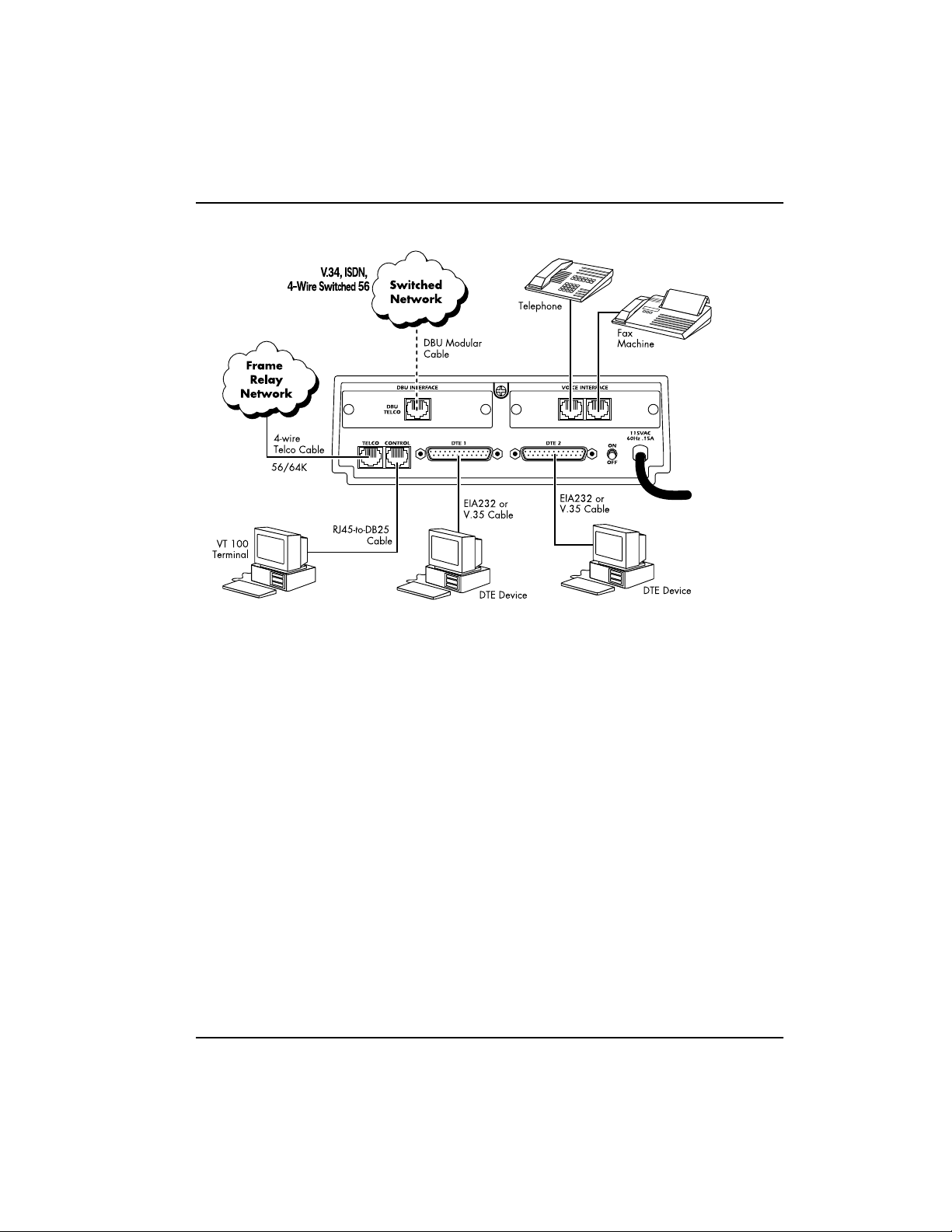
• Chapter 2, Installation, describes the Express 5200 connectors (pin assignments are given in Appendix A) and provides an installation diagram.
• Chapter 3, Operation, explains how to operate your Express 5200 using
either the front panel or a VT 100 terminal interface.
• Chapter 4, Applications, provides examples of some common Expr ess 5200
applications. This chapter includes network diagrams as well as configuration tables for each example.
• Chapter 5, Configuration Overview, explains how to access the
Express 5200 Configuration menu.
• Chapter 6 through 11 provide brief explanations for selections made in
the Configuration menus. These chapters are based on the first level
menu branches of the Configuration menu: DTE Ports, Voice Card
Options, Network Port, Dial Backup, IP Routing, and System configuration.
• Chapter 12, Statistics, describes how to access statistics information from
the Express 5200.
• Chapter 13, Testing, explains how to access the Express 5200 diagnostic
features, including ping and loopback tests.
• Chapter 14, Activating DBU Functions, provides information on the dialing options accessed through the Main menu.
• Appendix A provides pinouts for the Express 5200 connectors.
• Appendix B contains product specifications.
• Appendix C is a list of acronyms and abbreviations used in this document.
• Appendix D is a glossary of related terms.
61202175L1-1 Express 5200 User Manual iii
Page 4

Notes provide additional useful information.
Cautions signify informat ion that could prevent service interruption.
Warnings provide information that could prevent damage to the
equipment or endangerment to hum a n life.
IMPORTANT SAFETY INSTRUCTIONS
SAVE THESE INSTRUCTIONS
When using your telephone equipment, please f ollow these basic safety precautions
to reduce the risk of fire, electrical shock, or personal injury:
1. Do not use this product near water, such as near a bath tub, wash bowl, kitchen
sink, laundry tub, in a wet basement, or near a swimm ing pool.
2. Avoid using a telephone (other than a cordless-type) during an electrical storm.
There is a remote risk of shock from lightning.
3. Do not use the telephone to report a gas leak in the vicinity of the leak.
4. Use only the power cord, pow er supply, and/or batteries indicated in the ma nual.
Do not dispose of batteries in a fire. They may explode. Check with local codes
for special disposal instructions.
iv Express 5200 User Manual 61202175L1-1
Page 5

FCC regulations require that the following information be provided in this ma nual:
1. This equipment complies with Part 68 of FCC rules. On the bottom of the equip-
ment housing is a label showing the FCC registrat ion number and ringer equivalence number (REN) for this equipment. If requested, provide this information to
the telephone company.
2. If this equipment causes harm to the telephone network, the telephone company
may temporarily discontinue service. If possible, adva nce notification is given;
otherwise, notification is given as soon as possible. The telephone company will
advise the customer of the right to file a complaint with the FCC.
3. The telephone compan y may make changes in its facilities, equipment, opera-
tions, or procedures that could affect the proper operation of this equipment.
Advance notification and the opportunity to mainta in uninterrupted service are
given.
4. If experiencing difficulty with this equipment, please contact ADTRAN f or repair
and warranty information. The telephone company may require this equipment
to be disconnected from the network until the problem is corrected or it is certain
the equipment is not malfunctioning.
5. This unit contains no user-serviceable parts.
6. An FCC compliant telephone cord with a modular plug is provided with this
equipment. This equipment is designed to be connected to the telepho ne network
or premises wiring using an FCC compatible modular jack, which is Part 68 compliant.
7. The following information may be required when applying to the local telephone
company for a dial-up line for the V.34 modem:
Service Type Digital Facil-
ity Interface
Service
Order Code
Network
Jacks
Code
56 kbps Digital Interface 04DU5-56 6.0F RJ-48S
64 kbps Digital Interface 04DU5-64 6.0F RJ-48S
8. In the event of equipment malfunction, all repairs should be performed by
ADTRAN. It is the responsibility of users requiring service to report the need for
service to their distributor or ADTRAN. See the inside back cover of this manual
for information on contacting ADTRAN for service.
61202175L1-1 Express 5200 User Manual v
Page 6

ADTRAN Year 2000 (Y2K) Readiness Disclosure
ADTRAN has established a Year 2000 program to ensure that our products will correctly function in the new millennium. ADTRAN warrants that all products meet Year
2000 specifications regardless of model or revision. Information about ADTRAN's
Year 2000 compliance program is available at the following:
Product Matrix: www.adtran.com/y2kfax.html
E-mail: year2000@adtran.com
Faxback Document Line: (256) 963-8200
Y2K plans and product certifications are listed in the Product Matrix (see above)
Y2K Project Line: (256) 963-2200
vi Express 5200 User Manual 61202175L1-1
Page 7

FEDERAL COMMUNICATIONS COMMISSION
RADIO FREQUENCY INTERFERENCE STATEMENT
This equipment has been tested and found to comply with the limits for a Class A digital device, pursuant to Part 15 of the FCC Rules. These limits ar e designed to provide
reasonable protection against ha rmful interfer ence when the equipment is operated in
a commercial environment. This equipment generates, uses, and can radiate radio frequency energy and, if not installed and used in accordance with the instruction manual, may cause harmful interference to radio frequencies. Operation of this equipment
in a residential area is likely to cause harmful interference in which case the user will
be required to correct the interference at his own expense.
Shielded cables must be used with this unit to ensure compliance with Class A FCC
limits.
Changes or modifications to this unit not expressly approved by the party responsible for compliance could void the user's authority to operate
the equipment.
CANADIAN EMISSIONS REQUIREMENTS
This digital apparatus does not exceed the Class A limits for radio noise emiss ions
from digital apparatus as set out in the interference-causing equipment standard entitled “Digital Apparatus,” ICES-003 of the Department of Communications.
Cet appareil nuerique respecte les limites de bruits radioelectriques applicables aux
appareils numeriques de Class A prescrites dans la norme sur le materiel brouilleur:
“Appareils Numeriques,” NMB-003 edictee par le ministre des Communications.
61202175L1-1 Express 5200 User Manual vii
Page 8

CANADIAN EQUIPMENT LIMITATIONS
Notice: The Canadian Industry and Science Canada label identifies certified equipment. This certification means that the equipment meets certain telecommunications
network protective, operational, and safety requirements. The Department does not
guarantee the equipment will operate to the user’s satisfaction.
Before installing this equipment, users should ensure that it is permissible to be con nected to the facilities of the local telecommunications company. The equipment must
also be installed using an acceptable methods of connection. In some cases, the company’s inside wiring associated with a single line individual service may be extended
by means of a certified connector assembly (telephone e xtension cord). The customer
should be aware that compliance with the above limitations may not prevent degradation of service in some situations.
Repairs to certified equipment should be made by an authorized Canadian maintenance facility designated by the supplier. Any repairs or alterations made by the user
to this equipment, or equipment malfunctions, may give the telecommunications
company cause to request the user to disconnect the equipment.
Users should ensure for their own protection that the electrical ground connections of
the power utility, telephone lines and internal metallic water pipe system, if present,
are connected together. This precaution may be particularly important in rural areas.
Users should no t a ttempt to make suc h co nne ction s th emse lve s, bu t sho uld
contract the appropriate electric inspection authority, or an electrician, as
appropriate.
The Load Number (LN) assigned to each terminal device denotes the percentage of
the total load to be connected to a telephone loop which is used by the device, to prevent overloading. The termination on a loop may consist of any combination of
devices subject only to the requirement that the total of the Load Numbers of all
devices does not exceed 100.
viii Express 5200 User Manual 61202175L1-1
Page 9

Table of Contents
Chapter 1. Introduction
Understanding Frame Relay .............................................................................................. 1-1
Product Overview......................................................................................................... 1-2
DDS Operation.............................................................................................................. 1-3
SNMP..............................................................................................................................1-3
TELNET..........................................................................................................................1-4
Voice Compression....................................................... ...... ..... .....................................1-4
FXS Module ...........................................................................................................1-5
FXO Module ..........................................................................................................1-5
E&M Module .........................................................................................................1-5
Dial Backup Operation.................................................................................................1-5
Card Options .................................................................................................................1-6
Warranty and Customer Service................................................................................. 1-7
Chapter 2. Installation
Unpack, Inspect, Power Up ...............................................................................................2-1
Receiving Inspection.......................................... ..... ...... ................................................2-1
ADTRAN Shipments Include...................................................................................... 2-1
Customer Provides .......................................................................................................2-2
Power Up........................................................................................................................2-2
Rear Panel ............................................................................................................................. 2-2
DBU and Voice Interface Card Slots..........................................................................2-4
Telco Connector............................................................................................................. 2-4
Control Port ...................... ........................................................ ...... ...... ......................... 2-4
DTE Connectors ............................................................................................................ 2-4
Chapter 3. Operation
Front Panel ...........................................................................................................................3-1
LCD Window................................................................................................................. 3-1
Enter................................................................................................................................3-1
61202175L1-1 Express 5200 User Manual ix
Page 10

Table of Contents
Up and Down Arrows.................................................................................................. 3-1
Cancel..............................................................................................................................3-1
Numeric Keypad...........................................................................................................3-2
Next, Prev, Add, Delete................................................................................................ 3-2
Shift .................................................................................................................................3-2
LED Descriptions ..........................................................................................................3-2
Front Panel Operation.................................................................................................. 3-3
VT 100 Terminal Connection and Operation............................................................3-4
Express 5200 Menu Structure............................ ...... ..... ...............................................3-6
Main Menu .............................................................................................................3-7
Chapter 4. Applications
Data Applications ................................................................................................................ 4-1
SNA/SDLC with Local Spoofing................................................................................4-1
SNA and LAN Application with SNMP/TELNET Management .........................4-4
Bisync Application........................................................................................................4-7
Transparent Application............................................................................................4-10
Voice Applications ............................................................................................................4-12
Switched Mode Application......................................................................................4-12
External Call Origination ...................................................................................4-13
External Call Reception ......................................................................................4-13
Internal Calls ...................................................... ..... .............................................4-13
Voice Over Frame Relay Application....................................................... ................4-14
PLAR Mode Application............................................................................................4-15
Direct Mode Application............................................................................................4-16
Chapter 5. Configuration Overview
Local and Remote Configuration ......................................................................................5-1
Chapter 6. DTE Port Configuration
Port Disabled Protocol (DISABLE).............................................................................6 -3
Frame Relay Protocol....................................................................................................6-3
Physical Layer Options (PHYS LYR OPTS) ......................................................6-3
Protocol Options (PROTOCOL OPTS) ..............................................................6-5
Address Table (ADDR TABLE) ..........................................................................6-6
SDLC Protocol ...............................................................................................................6-7
Physical Layer Options (PHYS LYR OPTS) ......................................................6-7
Protocol Options (PROTOCOL OPTS) ..............................................................6-9
Address Table (ADDR TABLE) ........................................................................6-10
Transparent BOP Protocol (TRANS BOP)...............................................................6-11
Physical Layer Options (PHYS LYR OPTS) ....................................................6-12
x Express 5200 User Manual 61202175L1-1
Page 11

Table of Conten ts
Protocol Options (PROTOCOL OPTS) ............................................................6-13
Address Table (ADDR TABLE) ........................................................................ 6-13
Bisync Protocol............................................................................................................6-13
Physical Layer Options (PHYS LYR OPTS) .................................................... 6 -14
Protocol Options (PROTOCOL OPTS) ............................................................6-15
Address Table (ADDR TABLE) ........................................................................ 6-16
Transparent Async Protocol (TRANS ASYNC)......................................................6-17
Physical Layer Options (PHYS LYR OPTS) .................................................... 6 -18
Protocol Options (PROTOCOL OPTS) ............................................................6-19
Address Table (ADDR TABLE) ........................................................................ 6-19
PPP Synchronous Protocol (PPP SYNC) ................................................................. 6-20
Routing ................................................................................................................. 6-20
Physical Layer Options (PHYS LYR OPTS) .................................................... 6 -21
Address Table (ADDR TABLE) ........................................................................ 6-22
PPP Async Protocol ....................................................................................................6-22
Routing ................................................................................................................. 6-23
Physical Layer Options (PHYS LYR OPTS) .................................................... 6 -23
Address Table (ADDR TABLE) ........................................................................ 6-24
Slip Protocol................................................................................................................. 6-25
Routing ................................................................................................................. 6-25
Physical Layer Options (PHYS LYR OPTS) .................................................... 6 -25
Address Table (ADDR TABLE) ........................................................................ 6-27
Chapter 7. Voice Interface Configuration
Mode...............................................................................................................................7-1
Switched Mode .............................................................................................. ..... ...7-2
Direct Mode ...........................................................................................................7-2
Remote/Host (Rem/Host)..........................................................................................7-2
DLCI Mapping (DLCI MAP).......................................................................................7-2
Selections Available for a Unit in Direct Mode ................................................7-3
Selections Available for a Host Unit in Switched Mode .................................7-3
Min Jitter Buffers (MIN JITTER)................................................................................. 7-4
Max Jitter Buffers (MAX JITTER) ...............................................................................7-4
Extension Length (EXT LENGTH).............................................................................7-4
DTMF Gain ....................................................................................................................7-4
DTMF Sensitivity (DTMF SENS)................................................................................ 7-4
Regenerate DTMF (REGEN DTMF)...........................................................................7-4
Max Frame Repeat (MAX REPEAT).......................................................................... 7-4
Interface Type..................................................... ..... ......................................................7-4
Voice Coder............................................. ......................................................... ...... ..... ...7-5
Line 1 and L2 Options (L1 and L2 OPTIONS).......................................................... 7-5
61202175L1-1 Express 5200 User Manual xi
Page 12

Table of Contents
Chapter 8. Network Port Configuration
Network Port ........................................................................................................................8-1
Interface Type (INTERFACE)........................................................ ...... ...... ..... .............8-3
Physical Layer Options (PHYS LYR OPTS) ..............................................................8-3
Loop Rate ............................................................................................................... 8-3
Clock Source ..........................................................................................................8-4
Frame Relay Options (FR OPTS).................................................................................8-4
Signal Type (SIGNAL) .........................................................................................8 -5
T391 ......................................................................................................................... 8 -5
N391 ........................................................................................................................ 8-5
N392 and N393 ......................................................................................................8-5
Remote FECN Notification (REM FECN) ..........................................................8-6
LLC2 Options (LLC2 OPTS)........................................................................................8-6
LLC2 N2 Retry Counters (N2 RETRY) ...............................................................8-6
LLC2 k Window Size (WND SIZE) ....................................................................8-6
LLC2 Ack Timeout (ACK TO) .............................................................................8-6
LLC2 Poll Timeout (POLL TO) ...........................................................................8-6
LLC2 Busy Timeout (BUSY TO) .........................................................................8-7
LLC2 Reject Timeout (REJECT TO) ....................................................................8-7
LLC2 Keep-Alive Timeout (KA TO) ..................................................................8-7
IP Address......................................................................................................................8-7
Subnet Mask...................................................................................................................8-8
Transmit RIP Packets (XMIT RIP)...............................................................................8-8
Process Received RIP Packets (RIP PCKTS)..............................................................8-8
Priority Queue Ratio (N:1) (QUEUE RATIO)...........................................................8-8
PVC Options (PVC CONFIG)......................................................................................8-8
DLCI ........................................................................................................................ 8-8
DBU DLCI ..............................................................................................................8 -9
Next (NEXT key on front panel) .........................................................................8-9
Previous (PREV key on front panel) ..................................................................8-9
Add (ADD key on front panel) ...........................................................................8-9
Delete (DELETE key on front panel) ..................................................................8-9
Chapter 9. Dial Backup Configuration
Dial Backup Options ...........................................................................................................9-1
Auto DBU......................................................................................................................9-3
DBU Options..................................................................................................................9-3
DBU Criteria ..................................................................................................................9-4
DBU Timers....................................................................................................................9-4
DBU Card Options........................................................................................................ 9-5
ISDN DBU Card ....................................................................................................9-5
xii Express 5200 User Manual 61202175L1-1
Page 13

Table of Conten ts
V.34 DBU Card ...................................................................................................... 9-6
DCE Card ............................................................................................................... 9-6
Phone Numbers 1-5...................................................................................................... 9-6
Chapter 10. IP Routing
IP Routing with the Express 5200 ................................................................................... 10-1
IP Route Table ............................................................................................................. 10-3
Example Route Table Entry ...............................................................................10-4
Gateway IP Address (GW IP ADDRESS)................................................................10-5
Gateway Destination Port (GW DEST PORT)........................................................ 10-5
Gateway DLCI (GW DLCI) ....................................................................................... 10-5
Transmit ARP Packets (TX ARP)..............................................................................10-5
Process Received ARP Packets (RX ARP) ............................................................... 10-6
ARP Refresh Time (ARP REF)................................................................................... 10-6
Chapter 11. System Configuration
Change Password ....................................................... ........................................11-2
Read Community (RD COMMUNITY) ........................................................... 11-2
Write Community (WR COMMUNITY) ......................................................... 11-2
Trap Mgr Options (TRAP MGR OPTS) ........................................................... 11-2
Support Fragmentation (SUPPORT FRAG) .................................................... 11-3
System Time and Date .......................................................................................11-3
Entering Letters Using the Front Panel ..........................................................................11-3
Chapter 12. Statistics
Viewing Statistics Information (VT 100 Interface) ....................................................... 12-1
Hot Keys....................................................................................................................... 12-1
DTE and Network Ports.............................................................................................12-2
Current Status ...................................................................................................... 12-3
DLCI Statistics .....................................................................................................12-8
Protocol Statistics ................................................................................................12-8
System Statistics ..................................................................................................12-9
Voice Status .............................................................................................. ...... ....12-10
Viewing Statistics Information (Front Panel Interface) ............................................. 12-11
DTE Port Statistics .................................................................................................... 12-11
Network Port Statistics .................................................................................... 12-13
DLCI List ............................................................................................................ 12-14
System Status .....................................................................................................12-15
Status Information Available for the FXS/FXO/E&M Port ....................... 12-15
61202175L1-1 Express 5200 User Manual xiii
Page 14

Table of Contents
Chapter 13. Testing
Ping................................................................................................................................13-2
Address to Ping (PING ADDRESS) ..................................................................13-2
Start Ping ..............................................................................................................13-2
Voice..............................................................................................................................13-4
Lines 1 and 2 (FXS/FXO/E&M Cards) ............................................................13-4
Ring Test ...............................................................................................................13-4
Loopback .............................................................................................................. 13-4
Test Tone ..............................................................................................................13-5
Chapter 14. Activating DBU Functions
Dial Options .......................................................................................................................14-1
Options Available when Answer Unit is Connected to the DDS Line .......14-1
Options Available when Originate Unit is Connected to the DDS Line .....14-2
Options Available During Dial Backup ...........................................................14-2
Appendix A. Pinouts........................................................................................................ A-1
Appendix B. Specifications Summary ......................................................................... B-1
Appendix C. Acronyms/Abbreviations........................................................................ C-1
Appendix D. Glossary..................................................................................................... D-1
xiv Express 5200 User Manual 61202175L1-1
Page 15

List of Figures
Figure 2-1. Express 5200 Rear View.................................................................................2-3
Figure 3-1. Example of Basic Menu Navigation............................................................. 3-4
Figure 3-2. Terminal Login Menu.....................................................................................3-5
Figure 3-3. Terminal Main Menu...................................................................................... 3-6
Figure 3-4. Express 5200 Front Panel............................................................................... 3-9
Figure 4-1. SNA/SDLC with Local Spoofing.................................................................4-2
Figure 4-2. SNA and LAN Application with SNMP/TELNET Management........... 4-5
Figure 4-3. Bisync Point-to-Point ..................................................................................... 4-7
Figure 4-4. Bisync Multi-Point..........................................................................................4-8
Figure 4-5. Transparent BOP Application..................................................................... 4-10
Figure 4-6. Transparent Async Application...................................................................4-11
Figure 4-7. Switched Mode Application .......................................................................4-14
Figure 4-8. Voice Over Frame Relay Application.........................................................4-15
Figure 4-9. PLAR Mode Application .............................................................................4-16
Figure 4-10.Direct Mode Application.............................................................................4-17
Figure 5-1. VT 100 Configuration Menu (DBU card installed)....................................5-2
Figure 5-2. Terminal Configuration Menu Tree.............................................................. 5-3
Figure 6-1. VT 100 Port Configuration Menu................................................................. 6-1
Figure 6-2. Front Panel Protocol Menu Tree ................................................................... 6-2
Figure 6-3. Port Disabled Menu Tree...............................................................................6-3
Figure 6-4. Frame Relay Protocol Menu Tree ................................................................. 6-4
Figure 6-5. SDLC Protocol Menu Tree.............................................................................6-9
Figure 6-6. Transparent BOP Menu Tree ....................................................................... 6-12
Figure 6-7. Bisync Protocol Menu Tree.......................................................................... 6-14
Figure 6-8. Transparent Async Protocol Menu Tree ....................................................6-18
Figure 6-9. PPP Synchronous Protocol Menu Tree ......................................................6-21
61202175L1-1 Express 5200 User Manual xv
Page 16

Table of Contents
Figure 6-10.PPP Asynchronous Protocol Menu Tree....................................................6-24
Figure 6-11. SLIP Protocol Menu Tree .............................................................................6-26
Figure 7-1. Voice Options Menu.......................................................................................7-1
Figure 8-1. Network Port Configuration Menu Tree.....................................................8-2
Figure 8-2. VT 100 Network Port Configuration Menu................................................8-3
Figure 8-3. VT 100 Network Port Frame Relay Options Menu....................................8-4
Figure 8-4. VT 100 Network Port LLC2 Options Menu ................................................8-7
Figure 9-1. DBU Options Menu........................................................................................ 9-1
Figure 9-2. Dial Backup Menu Tree..................................................................................9-2
Figure 10-1. VT 100 IP Route Menu .................................................................................10-2
Figure 10-2. IP Routing Front Panel Menu Tree.............................................................10-3
Figure 10-3. IP Routing Table Menu ................................................................................10-4
Figure 11-1. System Configuration Menu....................................................................... 11-1
Figure 11-2. System Configuration Front Panel Menu..................................................11-2
Figure 12-1. Statistics Menu ..............................................................................................12-2
Figure 12-2. DTE Port View Statistics Menu-Frame Relay Protocol............................12-6
Figure 12-3. DTE Port View Statistics Menu (Trans Async) .........................................12-6
Figure 12-4. DTE Port View Statistics Menu-All Other Protocols ...............................12-7
Figure 12-5. Network Port View Statistics Menu...........................................................12-7
Figure 12-6. View DLCI Statistics Menu..........................................................................12-8
Figure 12-7. View Protocol Statistics Menu.....................................................................12-9
Figure 12-8. View System Statistics Menu..................................................................... 12-10
Figure 12-9. Example of Voice Status Menu (FXS Card Option)................................ 12-11
Figure 12-10.Front Panel Control Signal Status Screen...............................................12-12
Figure 12-11.Front Panel Signal State Screen................................................................12-14
Figure 12-12.Front Panel System Status Screen............................................................ 12-15
Figure 12-13.Front Panel System Date Screen..............................................................12-15
Figure 12-14.Front Panel System Time Screen..............................................................12-16
Figure 13-1. VT 100 Test Menu..........................................................................................13-1
Figure 13-2. Front Panel Test Menu..................................................................................13-2
Figure 13-3. VT 100 Ping Menu ........................................................................................13-3
Figure 13-4. Voice Interface Test Menu...........................................................................13-4
Figure 14-1. DBU Options Menu......................................................................................14-1
xvi Express 5200 User Manual 61202175L1-1
Page 17

List of Tables
Table 4-1. SNA/SDLC Application Configuration Settings....................................... 4-3
Table 4-2. SNA and LAN Application Settings............................................................4-6
Table 4-3. Multi-Point Bisync Application Settings.....................................................4-9
Table 4-4. Transparent BOP Application Settings .....................................................4-11
Table 4-5. Transparent Async Application Settings .................................................. 4-12
Table A-1. Telco Connector Pin Assignments ..............................................................A-1
Table A-2. DTE Connector Pin Assignments................................................................A-2
Table A-3. Control Connector Pin Assignments............................................. ...... ..... ..A-3
Table A-4. DBU Card Pin Assignments.........................................................................A-3
Table A-5. Voice Card Connector Pin Assignments....................................................A-4
Table A-6. DTE/DCE Connector Pin Assignments.....................................................A-5
Table A-7. Pin Assignment for V.35 Connector ........................................................... A-7
61202175L1-1 Express 5200 User Manual xvii
Page 18

Table of Contents
xviii Express 5200 User Manual 61202175L1-1
Page 19

Chapter 1 Introduction
UNDERSTANDING FRAME RELAY
Frame relay is a wide area network (WAN) service designed to
minimize physical connectio ns. This is accomplished by using
virtual connections within the frame relay cloud and accessing
these virtual circuits with normally one physical connection at each
location to the frame relay service. Virtual circuits are addressed
using header information at the beginning of each frame. These
frames are formatted by the user's CPE equipment such as the
ADTRAN Express 5200.
ANSI standards describe how each frame must be constructed to
provide interoperability between CPE equipment and frame relay
switching equipment. Each frame must contain a header, at least
one byte of information data, two bytes of CRC16, and a trailing
flag 0x7E.
This header information contains a virtual circuit addr ess known as
a DLCI (data link connection identifier). The header information
also contains bits used for network congestion control.
Frame relay virtual circuits may be defined as permanent (PVC) or
switched (SVC). PVCs have the same DLCI for a given path each
time a user protocol session is established. The network service
provider assigns these DLCIs at subscription time. SVCs, on the
other hand, have DLCIs dynamically assigned each time a user
protocol session is established. The CPE equipment must request a
call and the DLCI is assigned by the network switching equipment.
61202175L1-1 Express 5200 User Manual 1-1
Page 20

Chapter 1. Introduction
This DLCI is valid until the call is disconnected and may be
assigned a different value each time a call is requested.
Product Overview
The ADTRAN Express 5200 is a standalone frame relay access
device (FRAD) that provides a cost-effective means of transporting
voice and multi-protocol data over frame relay or DDS networks.
The Express 5200 provides an easy-to-use interface for customers
migrating existing services or developing new applications for
operation over frame relay networks.
The Express 5200 provides high-quality voice and fax capabilities
to remote locations without expensive toll charges. In frame relay
networks, the Express 5200 allows voice and data to share the same
PVC, eliminating unnecessary PVC charges associated with other
vendor’s voice and data frame relay products. Two voice ports are
provided when configured with a voice option card. Options
include: Dual FXS, Dual FXO, and Dual E&M.
The Express 5200 provides two independent DTE interfaces for
connecting non-frame relay devices to the frame relay network.
These ports can be configured for either EIA-232 or V.35 signal
specifications. Synchronous protocol speeds up to 512 kbps and
asynchronous protocol speeds up to 38.4 kbps are supported. See
the appendix Pinouts on page A-1 for the pin assignments for these
interfaces.
The Express 5200 handles each frame of the user data in a threestep manner. The first step is terminating the user protocol. The
layer at which this termination occurs varies, depending on the
user protocol selection for a given port. The next step is examining
the user protocol destination address and ro uting to the destination
port and virtual circuit. The last step involves encapsulating the
information field of each frame and re-encapsulating based on the
destination port configuration. A similar process is used for frame
relay frames received on the network port.
1-2 Express 5200 User Manual 61202175L1-1
Page 21

Chapter 1. Introduction
The major features of the Express 5200 are as follows:
• Dual voice port support; options include Dual FXS, Dual FXO,
and Dual E&M
• Two independent DTE data ports
• Integral 56/64 DDS DSU/CSU
• SNMP/TELNET management
• RFC 1490 encapsulation for IP and LLC2
• SDLC local port spoofing
• Automatic or manual dial backup for DDS operation
• Dial backup available with DBU cards; options include 4-wire
Switched 56, V.34, and ISDN
• Time of day and weekend dial backup lockout options
• Frame relay management using ANSI, ITU, or LMI formats
• Easy-to-use VT 100 interface for configuration
• Standard 5 year warranty
The 4-wire SW56 DBU card is compatible with AT&T Accunet and
Sprint SW56 type services. The V.34 DBU card allows switched
backup over the public switched telephone network (PSTN). The
ISDN 1B+D card supports a U- interface to the Basic R ate ISDN and
is compatible with National ISD N and AT&T DMS.
DDS Operation
DDS is a nationwide service that allows interconnection and
transportation of data at speeds up to 64 kbps. The local exchange
carriers provide the local loop service to DDS customers and may
provide data for routing Inter-LATA to an interexchange carrier.
The integrated 56/64 DDS DSU supports the 56/64 kbps DDS
service rate.
SNMP
The Express 5200's embedded SNMP feature allows the unit to be
accessed and controlled by a network manager through the
network interface or through a DTE port running frame relay, SLIP,
61202175L1-1 Express 5200 User Manual 1-3
Page 22

Chapter 1. Introduction
or async PPP protocol. The Express 5200 supports the MIB-II
standard, RFC 1213, and the ADTRAN Enterprise Specific MIB.
MIB files are available from ADTRAN in the support section of the
ADTRAN Web page at www.adtran.com.
The term SNMP broadly refers to the message protocols used to
exchange information between the network and the managed
devices, as well as to the structure of network management data
bases. SNMP has three basic components:
Network Manager
Control program that collects, contr ols, and pr esents data pertinent
to the operation of the network devices. It resides on a network
management stati on.
Agent
Control program that resides in each network device connected.
This program responds to queries and commands from the
network manager and returns requested information or invokes
configuration changes initiated by the m anager.
MIB
Index to the organized data within a netw ork device. It defines the
operation parameters that can be controlled or monitored.
TELNET
TELNET provides a password-protected, remote login facility to
the Express 5200. TELNET allows a user on a network manager to
control the Express 5200 through the terminal menus. See the
section SNA and LAN Application with SNMP/TELNET Management
on page 4-4 for more information.
Voice Compression
The Express 5200 voice option cards employ voice compression
technology to provide toll-quality voice using significantly less
bandwidth than traditional voice channels. In addition to
supporting voice calls, the cards support group 3 facsimile up to
1-4 Express 5200 User Manual 61202175L1-1
Page 23

FXS Module
FXO Module
E&M Module
Chapter 1. Introduction
14.4 kbps. The Express 5200 dynamically allocates bandwidth to
voice and data applications. This results in al l bandwidth being
available for data applications in the absence of voice or fax.
The FXS module provides two 2-wire compressed voice interfaces
and serves as the source of line current and ringing voltage. The
FXS serves as the station side of a foreign exchange FXS/FXO
application. The FXS may also be paired with another FXS to
provide private line automatic ringdown (PLAR) function across
the WAN.
The FXO module provides two 2-wire compressed voice interfaces
and provides a load for line current. The module includes a ring
detector and a line current detector. The FXO serves as the office
side of a foreign exchange FXS/FXO application.
The E&M module provides two 2- or 4-wire compressed voice
interfaces for use in E&M applications.
Dial Backup Operation
The Express 5200 supports dial backup of point-to-point DDS
circuits or point-to-point frame relay circuits. For DDS backup, the
Express 5200 enters dial backup based on physical line faults.
During dial backup, the Express 5200 monitors the main line
integrity and drops the dial backup call when the main line is
restored.
For frame relay dial backup, the Express 5200 monitors the physical
line condition as well as the signaling state of the frame relay
circuit. A loss of signaling on either end of the circuit causes the
Express 5200 to enter dial backup. During dial backup, the
Express 5200 constantly monitors the physical state of the network.
It also attempts to re-establish signaling on the main line. Once
61202175L1-1 Express 5200 User Manual 1-5
Page 24

Chapter 1. Introduction
both the physical integrity and the signaling state are restored, the
unit drops the dial backup call and reverts to the main line.
For frame relay dial backup, either Express 5200 can originate a dial backup connection. The answer/originate option has no effect in frame relay
mode.
Only point-to-point frame relay is s upporte d with the Express 5200. The
Express 5200 only supports one network connection at a time. Therefore,
when a dial backup connection is made, the main network port is disconnected from the data path. This isolates any other nodes on a frame relay
network if a dial backup connection is established with a single node.
The Express 5200's unique DBU cards are field-installable by the
customer. See the section DBU and Voice Interface Card S lot s on page
2-4 for information on installing DBU cards. The four backup
options are described in the following sectio ns. Contact the local
telco provider to determine which services are available in your
area.
Card Options
4-Wire Switched 56 DBU Card
This dial-up 4-wire SW56 card allows you to pay for data
connection only for the time the unit is active. The regional
operating companies provide the 4-wire local loop service to SW56
customers.
V.34 DBU Card
This module backs up the leased line application at data rates up to
33.6 kbps over an ordinary telephone network.
ISDN DBU Card
1B+D Basic Rate ISDN service provides a switched 56/64 kbps
circuit.
DCE Card
This module connects an external DCE device to the Express 5200
for the purpose of using an external DSU/CSU to support access
rates up to 512 kbps. The DCE card is inserted into the DBU card
slot, but it is not used for dial backup.
1-6 Express 5200 User Manual 61202175L1-1
Page 25

Warranty and Customer Service
ADTRAN will replace or repair this product within five years from
the date of shipment if it does not meet its published specification s
or fails while in service. For detailed warranty, repair, and return
information refer to the ADTRAN Equipment Warranty and Repair
and Return Policy Procedure.
Return Material Authorization (RMA) is requir ed prior to returning
equipment to ADTRAN.
For service, RMA requests, or further information, contact one of
the numbers listed on the inside back cover of this manual.
Chapter 1. Introduction
61202175L1-1 Express 5200 User Manual 1-7
Page 26

Chapter 1. Introduction
1-8 Express 5200 User Manual 61202175L1-1
Page 27

Chapter 2 Installation
UNPACK, INSPECT, POWER UP
Receiving Inspection
Carefully inspect the Express 5200 for any damage that may have
occurred in shipment. If damage is suspected, file a claim
immediately with the carrier and contact ADTRAN Technical
Support (see the back cover of this manual). Keep the original
shipping container to use for future shipment or verification of
damage during shipment.
ADTRAN Shipments Include
The following items are included in ADTRAN shipments of the
Express 5200:
• Express 5200 unit
• User manual
• An 8-position modular to 8-position modular cable
• VT 100 terminal adapter cable (consists of a DB-25 modular
adapter and an 8-position to 8-position modular cable)
The ADTRAN Express 5200 MIB is available in the suppo rt section of
the ADTRAN Web page at www.adtran.com.
61202175L1-1 Express 5200 User Manual 2-1
Page 28

Chapter 2. Insta llation
The following items are included in ADTRAN shipments of DBU
cards:
• DBU card
• An 8-position modular to 8-position modular cable for the
4-wire SW56 and ISDN DBU card, or
• An 8-position modular to 4-position modular cable for the V.34
DBU card.
Customer Provides
The customer provides an interface cable for each port used. Each
cable should be either an EIA-232 with a standard 25-pin male
D-type connector or a V.35 cable. V.35 requires an ADTRAN
adapter cable (part numbers: male 1200193L1; female 1200194L1).
Power Up
Each Express 5200 unit is provided with a captive eight-foot power
cord, terminated by a three-prong plug which connects to a
grounded 115 VAC power receptacle.
Power to the Express 5200 must be provided from a grounded 115 VAC,
60 Hz receptacle.
REAR PANEL
The Express 5200 is equipped with two DB-25 connectors labeled
DTE 1
interface are provided through the 8-pin telco jacks labeled
and
the appendix Pinouts on page A-1. The Express 5200 rear panel is
shown in Figure 2-1.
2-2 Express 5200 User Manual 61202175L1-1
DTE 2
and
CONTROL
. Connections to the dedicated circuit and VT 100
TELCO
. Pin assignments for these connectors are given in
Page 29
Chapter 2. Installation
Item Function
DBU Interface
Voice Interface
Telco port
Control port
DTE 1 port
DTE 2 port
On/Off Switch
115 VAC connection
DBU or DCE card slot
FXS, FXO, E&M card slot
Connects to the dedicated circuit
Connects to the VT 100 interface
Connects to a DTE device
Connects to a DTE device
Turns power on and off
Connects to captive power cord
Figure 2-1. Express 5200 Rear View
61202175L1-1 Express 5200 User Manual 2-3
Page 30

Chapter 2. Insta llation
DBU and Voice Interface Card Slots
The Express 5200 rear panel has two card slots for the installation of
dial backup, voice, and DCE interface cards. To insert cards,
perform the following procedure:
1. Remove power from the Express 5200.
2. Slide the card into the corresponding rear slot until the card
panel is flush with the Express 5200 chassis.
3. Push card locks in (until they click) to secure the card and
ensure proper installation.
Card slots are keyed to prevent improper installation (i.e., putting a DBU
card into the voice slot).
Telco Connector
TELCO
The
provides connection to a dedicated 56/64 kbps network. See Ta ble
A-1 in the Pinouts appendix for the
assignments.
connector is an eight-position modular jack which
TELCO
connector's pin
Control Port
The eight-position modular jack labeled
connection to a VT 100 EIA-232 compatible interface. This enables
the Express 5200 to be configur ed through a terminal instead of the
front panel. Use the VT 100 terminal cable (provided) for this
connection. See Tabl e A-3 in the Pinouts appendix for the connector
pin assignments. A description of the operation of this port is
covered in the section VT 100 Terminal Connection and Operation on
page 3-4.
CONTROL
provides
DTE Connectors
DTE devices are connected to the
EIA-232 DTE cable or an ADTRAN V.35 DTE adapter cable. The
2-4 Express 5200 User Manual 61202175L1-1
DTE
connectors using either an
Page 31

Chapter 2. Installation
maximum cable lengths recommended are 50 feet for the EIA-232
and 100 feet for the V.35. The pin assignments are listed in Ta ble A-2
of the appendix Pinouts.
The V.35 adapter cable is recommended for use with data rates
above 19.2 kbps. A low capacitance EIA-232 cable works up to 56
kbps. The DTE ports are configured through the front panel or the
VT 100 control po rt. The D TE ports ca n oper ate in asynchronous or
synchronous modes.
61202175L1-1 Express 5200 User Manual 2-5
Page 32

Chapter 2. Insta llation
2-6 Express 5200 User Manual 61202175L1-1
Page 33

Chapter 3 Operation
FRONT PANEL
The Express 5200 faceplate is shown in Figure 3-4 on page 3-9.
Descriptions of each part of the front panel follow.
LCD Wind ow
Displays menu items and messages in 2 lines by 16 characters.
Enter
Selects active menu items. To activate a menu item, scroll to it
using the arrow keys or press the number of the item. The flashing
cursor indicates which parameter is activated. Press
select the active menu item.
Up and Down Arrows
ENTER
to
Up and down arrows scroll through and activate the submenu
items available in the current menu. The flashing cursor indicates
the active parameter.
Cancel
Pressing the
the previous menu. Repeat until the desir ed menu level is rea ched.
61202175L1-1 Express 5200 User Manual 3-1
CANCEL
key stops the current activity and returns to
Page 34

Chapter 3. Operation
When a submenu item is displayed, press
current display and return to the previous menu.
Numeric Keypad
The numeric keypad contains the numbers 0 through 9 and alpha
characters
A
throug h F, which are used to activate menu items and
enter information such as the IP address.
Next, Prev, Add, Delete
To activate these functions, press and release the
then press the
NEXT, PREV, ADD
when editing routing tables.
Shift
Enter alpha characters by pressing and releasing the
before pressing the desired character. The
DELETE
To activate a menu item designated by an alpha character rather
than a number, place the cursor on the menu item using the up and
down arrows or press
cursor indicates the activated parameter. Press
item.
keys are also activated by first pressing
CANCEL
DELETE
, or
SHIFT
and then the letter. The flashing
key. Use these keys
NEXT, PREV, ADD
ENTER
to exit the
SHIFT
key, and
SHIFT
SHIFT
.
to select the
key
, and
LED Descriptions
The Express 5200 has seven LED indicators:
TDN, RDN
, and
ALM/TST
. These LEDs are identified as follows:
TD1: Trans mit Data (DTE 1)
This LED is active when the Express 5200
data.
RD1: Receive Data (DTE 1)
This LED is active when the Express 5200
data.
3-2 Express 5200 User Manual 61202175L1-1
TD1, RD1, TD2, RD2
DTE 1
port is transmitting
DTE 1
port is receiving
,
Page 35

Chapter 3. Operation
TD2: Trans mit Data (DTE 2)
This LED is active when the Express 5200
DTE 2
port is transmitting
data.
RD2: Receive Data (DTE 2)
This LED is active when the Express 5200
DTE 2
port is receiving
data.
TDN: Transmit Data (Network)
This LED is active when the Express 5200
NETWORK
port is
transmitting data.
RDN: Receive Data (Network)
This LED is active when the Express 5200
NETWORK
port is
receiving data.
ALM/TST: Alarm/Test
This LED is active when an alarm condition exists or when the unit
is in test mode. Alarm conditions include:
DDS Alarm Conditions
• Open loop on network
• No frame synchronization
• OOS/OOF
Frame Relay Alarm Condition
• Network frame relay signaling state down
Front Panel Operation
To choose a menu item, press the corresponding num ber or alp h a
character on the keypad. Press
alpha selections. Scrolling to the selection by using the up and
down arrows also activates the menu items. The flashing cursor
indicates the activated selection. Press
The following steps and Figure 3-1 illustrate how to select
Express 5200 options:
C
1. Activate
pressing
ONFIGURATION
1
. The cursor will flash on the number next to the
activated selection. Press
2. Use the arrow keys to view submenu items.
61202175L1-1 Express 5200 User Manual 3-3
SHIFT
C
ONFIG
(
ENTER
to activate menu items with
ENTER
to select the item.
) by using the arrow keys or
.
Page 36

Chapter 3. Operation
3. Choose an item on the submenu such as
4. Activate
Press
5. Activate
D
ENTER
P
pressing
TE PORT
ROTOCOL
1
. Press
.
1
by using the arrow keys or pressing
options by using the arrow keys or
ENTER
.
D
TE PORT
1
6. Press the arrow keys until the desired protocol is displayed.
Press
1 CONFIG
ENTER
1 DTE PORT 1 1 PROTOCOL
2 DTE PORT 2 2 PHYS LYR OPTS 4 TRANS BOP
3 FXS/FXO/ E &M OPTIONS 3 PROTOCOL OPTS 5 BISYNC
4 NETWORK PORT 4 ADDR TABLE 6 TRANS ASYNC
5 DBU 7 PPP SYNC
6 CONTROL PORT 8 PPP ASYNC
7 IP ROUTING 9 SLIP
8 SYSTEM
.
1 DISABLE
2 FRAME RELAY
3 SDLC
Figure 3-1. Example of Basic Menu Navigation
.
1
.
VT 100 Terminal Connection and Operation
To control the Express 5200 using a VT 100 terminal, perform the
following procedure:
1. Set the Express 5200 baud rate to match the terminal through
C
1
the front panel. Select
ONFIG
2. Using the provided VT 100 terminal adapter cable, connect the
COM
port of a VT 100 compatible terminal or equivalent to the
eight-pin modular jack labeled
Express 5200. This connection is used for both local and remote
configuration.
3. Open the connection and press the terminal keyboard's
L
key repeatedly until the
3-4 Express 5200 User Manual 61202175L1-1
OGIN MENU
C
, then
CONTROL
ONTROL PORT
on the rear of the
appears (Figure 3-2).
.
Enter
Page 37

Chapter 3. Operation
L
4. Select
connected to the terminal. Select
OCAL LOGIN
to configure the Express 5200 unit
R
EMOTE LOGIN
to configure a
remotely located Express 5200 unit. For remote applications,
enter the
remote unit by pressing
again. Next sele ct
Enter
5. Enter the password. The factory default password is
The
DLCI
(data link connection identifier) number of the
1, Enter
B
EGIN REMOTE SESSION
, the DLCI number, and
.
M
AIN
menu will appear, as shown in Figure 3-3.
Enter
by pressing 2 and
adtran
.
6. Make selections by entering the number corresponding to the
chosen parameter. Press
ESC
to return to the previous screen.
L
In the upper right-hand corner of the VT 100 screen,
OCAL
or
is displayed, indicati ng which unit the current screen represents.
.
Figure 3-2. Terminal Login Menu
R
EMOTE
61202175L1-1 Express 5200 User Manual 3-5
Page 38

Chapter 3. Operation
Express 5200 Menu Structure
Figure 3-3. Terminal Main Menu
The opening menu is the access point to all other operatio ns. Each
M
AIN
menu item has several functions and submenus to identify
and access specific parameters.
L
OGOUT
The
D
IAL BACKUP
selection is available on the VT 100 interface only. The
D
IAL
and
selections are available only when a DBU card
is installed.
In this chapter, the VT 100 selections are listed first followed by the front
panel selections (if the names differ).
3-6 Express 5200 User Manual 61202175L1-1
Page 39

Main Menu
Chapter 3. Operation
M
Definitions for the branches of the
AIN
menu follow:
Configuration (CONFIG)
C
ONFIGURATION
is used to set network operating parameters for the
DTE, voice, network, and dial backup interfaces. IP routing and
C
system configuration optio ns are also found in the
ONFIGURATION
menus. The chapter Configuration Overview on page 5-1 explains
how to access these menus. Chapters 6 through 11 provide brief
C
explanations for each
based on the first level menu branches of the
ONFIGURATION
selection. The chapters are
C
ONFIGURATION
menu:
DTE Port Configuration begins on page 6-1; Voice Interface
Configuration begins on page 7-1; Network Port Configuration begins
on page 8-1; Dial Backup Configuration begins on page 9-1; IP
Routing begins on page 10-1; and System Configuration begins on
page 11-1.
DTE P
When
the selections for
A
DDRESS TABLE
1
ORT
or 2 is selected, the
P
HYSICAL LAYER OPTIONS
P
ROTOCOL
P
ROTOCOL OPTIONS
,
enabled determines
. See the chapter DTE Port Configuration on page 6-1
, and
for more information.
View Statistics (STATS)
This selection displays status inf ormation for DTE ports, the
network port, the protocol, the system, and the voice car ds. See the
chapter Statistics on page 12-1 for more information.
Test
Testing options enable and disable voice and ping test functions.
See the chapter Testin g on page 13-1 for more information.
Dial (available when DBU card is installed)
This selection allows you to access DBU functions. See the chapter
Activating DBU Functions on page 14-1 for more information.
Save Configuration (SAVE)
This parameter saves the currently selected configuration.
S
Configurati on changes a re not impl emented un til the
S
TION
AVE
(
) option is selected.
AVE CONFIGURA
-
61202175L1-1 Express 5200 User Manual 3-7
Page 40

Chapter 3. Operation
Abort Changes (ABORT)
This parameter cancels the current selections and reverts to the last
saved configuration.
Logout (VT 100 menu only)
This parameter logs out of the system.
3-8 Express 5200 User Manual 61202175L1-1
Page 41

Chapter 4 Applications
This chapter provides examples of some common Express 5200
data and voice applications. The data examples include SNA/
SDLC with local spoofing, SNMP/TELNET management, bisync
point-to-point, bisync multi-poin t, and transparent applications.
The voice applications include switched, voice over frame relay,
PLAR circuits, and direct FXS/FXO. The configuration selections
given in these examples may need modification based on your
network configuration.
DATA APPLICATIONS
SNA/SDLC with Local Spoofing
When used in an SNA/SDLC network, the Express 5200 provides
local spoofing by emulating the prim ary or secondary SDLC roles
(see Figure 4-1). The Express 5200 performs conversion from SDLC
to frame relay and also terminates SDLC links, providing primary
and secondary emulation between Express 5200s. Local spoofing
improves performance by reducing traffic across the frame relay
network and allows definite response times on the SDLC links.
To perform spoofing, the Express 5200 automatically sets itself up
to provide primary or secondary emulation based on the receipt of
SNRM (set normal response mode) from an SDLC device. The
Express 5200 looks for SNRM on all ports and assumes a secondary
role once SNRM is received. The Express 5200 then brings up the
LLC2 link across the frame relay network to another FRAD which
61202175L1-1 Express 5200 User Manual 4-1
Page 42

Chapter 4. Applications
assumes a primary role. This allows the Express 5200 to operate
with PU 2.1 devices.
Different roles can be assumed for each SDLC session. Disconnection starts the role determination procedure again.
In all cases, the Express 5200 is transparent to the XID (exchange identification) negotiation between any two network devices.
The Express 5200 uses LLC protocol (mode 2) to transport SDLC
information frames. This protocol ensures a reliable link across
frame relay, providing protection from frame loss and excessive
delays. The encapsulation method uses the RFC 1490 format. See
Tab le 4-1 for an example of how to configure the Express 5200 for
this application.
Figure 4-1. SNA/SDLC with Local Spoofing
4-2 Express 5200 User Manual 61202175L1-1
Page 43

DTE Port 1
Protocol
Physical Layer
Options
Protocol
Options
Address Table
DTE Port 2
Protocol
Physical Layer
Options
Protocol
Options
Address
Table
Network Port
Physical Layer
Options
Frame Relay
Options
Chapter 4. Applications
Table 4-1. SNA/SDLC Application Configuration Settings
HOST 5200 REMOTE 5200
SDLC SDLC
INTERFACE=EIA-232 INTERFACE=EIA-232
BIT RATE=19.2K BIT RATE=19.2K
TX IDLE CODE=ONES TX IDLE CODE=ONES
HDW FLOW CTRL=ON HDW FLOW CTRL=ON
TIMEOUT=3 TIMEO UT=3
MIN POLL TIME=0 MIN POLL TIME=0
POLL RATIO=1 POLL RATIO=1
THRESHOLD=10 THRESHOLD=10
TX DELAY=0 TX DELAY=0
CTS OPTION=FOLLOW RTS CTS OPTION=FOLLOW RTS
ENTRY #1 ENTRY #2 ENTRY #1
PU ADDRESS=C0 PU ADDRESS=C1 PU ADDRESS=C0
GROUP ADDR=0 GROUP ADDR=0 GROUP ADDRESS=0
LLC2 SSAP=04 LLC2 SSAP=08 LLC2 SSAP=04
LLC2 DSAP=04 LLC2 DSAP=04 LLC2 DSAP=04
OUT DLCI=120 OUT DLCI=120 OUT DLCI=17
DISABLE SDLC
N/A INTERFACE=EIA-232
BIT RATE=19.2K
TX IDLE CODE=ONES
HDW FLOW CTRL=EN
TIMEOUT=3
MIN POLL TIME=0
POLL RATIO=1
THRESHOLD=10
TX DELAY=0
CTS OPTION=FOLLOW RTS
ENTRY #1
PU ADDRESS=C1
GROUP ADDR=0
LLC2 SSAP=04
LLC2 DSAP=08
OUT DLCI=17
LOOP RATE=64K
CLOCK SOURCE=FROM NETWORK
SIGNAL=ANSI SIGNAL=ANSI
T391=10 T391=10
N391=6 N391=6
N392=3 N392=3
N393=4 N393=4
REM FECN=NO REM FECN=NO
LOOP RATE=64K
CLOCK SOURCE=FROM NETWORK
61202175L1-1 Express 5200 User Manual 4-3
Page 44

Chapter 4. Applications
SNA and LAN Application with SNMP/TELNET
Management
When used in a mixed environment consisting of both SNA and
LAN networks, the Express 5200 serves as a concentrator, allowing
both networks access to one frame relay link. The example shown
in Figure 4-2 shows
previous example).
DTE 1
DTE 2
configured for
is configured for
protocol, providing the LAN gateway/router with frame relay
access.
SDLC
protocol (as in the
F
RAME RELAY
DTE
port while
DTE 2
The Express 5200 routes data at the DLCI level using the
A
frame relay
DDRESS TABLE
. The Express 5200 emulates the
network end of the UNI signaling protocol for the
emulating the CPE end for the network port. PVC status
information from the frame relay network is stored and used for
full status requests from the router attached to the
DTE
port.
A local DLCI is set up between the router and the Express 5200.
This
M
ANAGEMENT
DLCI
carries the SNMP and TELNET traffic
destined for the Express 5200. This DLCI is included in the UNI
IP A
full status responses to the router. The Express 5200
must be mapped to the
M
ANAGEMENT
DLCI
in the LAN router's
DDRESS
route table (see the following note). With this path, an SNMP
manager located anywhere in the network can access the
Express 5200's SNMP and TELNET information. See Table 4-2 for
an example configuration.
RIP and inve rse A RP are n ot us ed for the E xpress 5200 DTE frame relay
port.
4-4 Express 5200 User Manual 61202175L1-1
Page 45

Chapter 4. Applications
Figure 4-2. SNA and LAN Application with SNMP/
TELNET Management
61202175L1-1 Express 5200 User Manual 4-5
Page 46

Chapter 4. Applications
DTE Port 1
Protocol
Physical Layer
Options
Protocol
Options
Address
Table
DTE Port 2
Protocol
Physical Layer
Options
Protocol Options
Protocol Address
Table
Network Port
Physical Layer
Options
Frame Relay
Options
Table 4-2. SNA and LAN Application Settings
HOST 5200 REMOTE 5200
SDLC SDLC
INTERFACE=EIA 232 INTERFACE=EIA 232
BIT RATE=19.2K BIT RATE=19.2K
TX IDLE CODE=ONES TX IDLE CODE=ONES
HDW FLOW CTRL=ON HDW FLOW CTRL=ON
TIMEOUT=3 TIMEOUT=3
MIN POLL TIME=0 MIN POLL TIME=0
POLL RATIO=1 POLL RATIO=1
THRESHOLD=10 THRESHOLD=10
TX DELAY=0 TX DELAY=0
CTS OPTION=FOLLOW RTS CTS OPTION=FOLLOW RTS
ENTRY #1 ENTRY #2
PU ADDRESS=C0 PU ADDRESS=C0
GROUP ADDR=0 GROUP ADDR=0
LLC2 SSAP=04 LLC2 SSAP=04
LLC2 DSAP=04 LLC2 DSAP=04
OUT DLCI=120 OUT DLCI=17
DISABLED FRAME RELAY
N/A INTERFACE=V.35
BIT RATE=64K
TX IDLE CODE=FLAGS
HDW FLOW CTRL=ON
N/A T392=15
N392=3
N393=4
IP ADDRESS=200.200.200.2
SUBNET MASK=255.255.255.0
MGMT DLCI=960
N/A NET DLCI=18
LOOP RATE=64K LOOP RATE=64K
CLOCK SOURCE=FROM NETWORK CLOCK SOURCE=FROM NETWORK
SIGNAL=ANSI SIGNAL= ANSI
T391=10 T391=10
N391=6 N391=6
N392=3 N392=3
N393=4 N393=4
REM FECN=NO REM FECN=NO
4-6 Express 5200 User Manual 61202175L1-1
Page 47

Bisync Application
The Express 5200 can be used to connect IBM 3780/2780 (see IBM
manual number GA27-3004-2) bisync con trollers and a host across
a frame relay network. Point-to-point and mu lti-point configurations are supported at speeds up to 19.2 kbps. The LLC protocol
(mode 2) is used to provide a reliable transport layer across the
frame relay network. In a multi-point configuration, the
Express 5200 performs local spoofing, minimizing traffic across the
frame relay network. Sample network illustrations for both
point-to-point and multi-point are shown in Figure 4-3 and Figure
4-4.
See Tab le 4-3 for an example configuration of the multi-point
application.
Chapter 4. Applications
Figure 4-3. Bisync Point-to-Point
61202175L1-1 Express 5200 User Manual 4-7
Page 48

Chapter 4. Applications
Figure 4-4. Bisync Multi-Point
4-8 Express 5200 User Manual 61202175L1-1
Page 49

DTE Port 1
Protocol
Physical Layer
Options
Protocol
Options
Address Table
DTE Port 2
Protocol
Physical Layer
Options
Protocol
Options
Address Table
Network Port
Physical Layer
Options
Frame Relay
Options
Chapter 4. Applications
Table 4-3. Multi-Point Bisync Application Settings
HOST 5200 REMOTE 5200
BISYNC BISYNC
INTERFACE=EIA-232 INTERFACE=EIA-232
BIT RATE=9600 BIT RATE=9600
TX IDLE CODE=FLAGS TX IDLE CODE=FLAGS
HDW FLOW CTRL=ON HDW FLOW CTRL=ON
LINE=MULTI LINE=MULTI
TRANSLAT CODE= EBCDIC CRC16 TRANSLAT CODE= EBCDIC CRC16
TIMEOUT=3 TIMEOUT=3
THRESHOLD=10 THRESHOLD=10
POLL RATIO=1 POLL RATIO=1
CTS OPTION=FOLLOW RTS CTS OPTION=FOLLOW RTS
FORMAT=NRZ FORMAT=NRZ
ENTRY #1 ENTRY #2 ENTRY #1
POLL ADDR=AA1 POLL ADDR=BB1 POLL ADDRESS=AA1
LLC2 SSAP=04 LLC2 SSAP=04 LLC2 SSAP=04
LLC2 DSAP=04 LLC2 DSAP=08 LLC2 DSAP=04
OUT DLCI=120 OUT DLCI=120 OUT DLCI=17
DISABLED BISYNC
N/A INTERFACE=EIA-232
BIT RATE=9600
N/A LINE=MULTI
TRANSLAT CODE= EBCDIC CRC16
TIMEOUT=3
THRESHOLD=10
POLL RATIO=1
FORMAT=NRZ
N/A ENTRY #1
POLL ADDRESS=BB1
LLC2 SSAP=08
LLC2 DSAP=04
OUT DLCI=17
LOOP RATE=64K LOOP RATE=64K
CLOCK SOURCE=FROM NETWORK CLOCK SOURCE=FROM NETWORK
SIGNAL=ANSI SIGNAL=ANSI
T391=10 T391=10
N391=6 N391=6
N392=3 N392=3
N393=4 N393=4
REM FECN=NO REM FECN=NO
61202175L1-1 Express 5200 User Manual 4-9
Page 50

Chapter 4. Applications
Transparent Application
In cases when the user protocol is not supported by the
Express 5200, the transparent mode may be used. Transparent bitoriented protocol (BOP) or transparent asynchronous protocol may
be selected. This can be used for point-to-point connections only
because the Express 5200 is transparent to the protocol address
formats.
In the
T
RANSPARENT
BOP
protocol, the Express 5200 accepts an
HDLC-like protocol and encapsulates the information field of the
HDLC frames, transporting them across the frame relay network to
the specified virtual circuit and remote Express 5200 port number.
The incoming frames must be spaced with at least one flag byte
(0x7E) and contain two bytes of CRC16 at the end of each frame.
T
Asynchronous protocols are supported by using the
A
SYNC
mode. The Express 5200 buffers async characters and
RANSPARENT
encapsulates the data portion of each character for transport across
frame relay using a programmable DLCI and remote Express 5200
port number.
See Figure 4-5 and Tabl e 4- 4 for an example of a transparent BOP
configuration. See Figure 4-6 and Table 4-5 for an example of a
transpar e n t as ynchronous applica t io n.
Figure 4-5. Transparent BOP Application
4-10 Express 5200 User Manual 61202175L1-1
Page 51

DTE Port 1
Protocol
Physical Layer
Options
Protocol Options
Address Table
DTE Port 2
Protocol
Network Port
Physical Layer
Options
Frame Relay
Options
Chapter 4. Applications
Table 4-4. Transparent BOP Application Settings
LOCAL 5200 REMOTE 5200
TRANS BOP TRANS BOP
INTERFACE=V.35 INTERFACE=V.35
BIT RATE=64K BIT RATE=64K
TX IDLE CODE=FLAGS TX IDLE CODE=FLAGS
HDW FLOW CTRL=ON H DW FLOW CTRL=ON
N/A N/A
FAR END PORT=DTE 1 FAR END PORT=DTE 1
OUT DLCI=100 OUT DLCI=17
DISABLED DISABLED
LOOP RATE=64K LOOP RATE=64K
CLOCK SOURCE=FROM NETWORK CLOCK SOURCE=FROM NETWORK
SIGNAL=ANSI SIGNAL=ANSI
T391=10 T391=10
N391=6 N391=6
N392=3 N392=3
N393=4 N393=4
REM FECN=NO REM FECN=NO
Figure 4-6. Transparent Async Application
61202175L1-1 Express 5200 User Manual 4-11
Page 52

Chapter 4. Applications
DTE Port 1
Protocol
Physical Layer
Options
Protocol Options
Address Table
DTE Port 2
Protocol
Network Port
Physical Layer
Options
Frame Relay
Options
Table 4-5. Transparent Async Application Settings
HOST 5200 REMOTE 5200
TRANS ASYNC TRANS AS YNC
INTERFACE=EIA-232 INTERFACE=EIA-232
BIT RATE=38.4K BIT RATE=38.4K
DATA BITS=8 DATA BITS=8
PARITY=NONE PA RITY=NONE
STOP BITS=1 STOP BITS=1
HDW FLOW CTRL=ON HDW FLOW CTRL=ON
FRM SIZE=100 FRM SIZE=100
MAX IDLE=2 M AX IDLE=2
FAR END PORT=DTE 1 FAR END PORT=DTE 1
OUT DLCI=100 OUT DLCI=17
DISABLED DISABLED
LOOP RATE=64K LOOP RATE=64K
CLOCK SOURCE=FROM NETWORK CLOCK SOURCE=FROM NETWORK
SIGNAL=ANSI SIGNAL=ANSI
T391=10 T391=10
N391=6 N391=6
N392=3 N392=3
N393=4 N393=4
REM FECN=NO REM FECN=NO
VOICE APPLICATIONS
Switched Mode Application
Switched mode is used to multiplex several remote extensions (up
to 40) to two host ports (see Figure 4-7). This enables many remote
users to have access to a limited number of access lines on a call-bycall basis. The host unit typically connects two extensions to a PBX
via an FXO module. The remote units connect to telephone sets via
FXS modules.
The host unit is programmed with the extensions and DLCI
information for all of the remote units. This information is
communicated to the remote units over the network.
4-12 Express 5200 User Manual 61202175L1-1
Page 53

External Call Origination
When the telephone set on a remote Express 5200 is taken off-hook,
the local Express 5200 generates dial tone and waits for an
extension to be entered by the user. Once the extension is entered,
the remote Express 5 200 transmits this information to the host
Express 5200, where it is compared to extension information in the
extension/DLCI table. If the extension is not located, the host
assumes the number is external and attempts to seize an available
port and dial the extension on the PBX. If no port is available, a
trunk busy (fast busy) is returned to the remote port. After the
extension is dialed, the data link is established and the call remains
up until the remote Express 5200 terminates the call.
External Call Reception
When an incoming call is received from the PBX, the remote
Express 5200 auto-answers the call and generates a dial tone. At
this point, the calling party can dial the extension of the party they
are trying to reach. The host looks up the extension in the
extension/DLCI table and routes the call appropriately. If the
extension does not exist, the Express 5200 generates a trunk busy
signal back into the PBX. Otherwise, the host routes the call to the
appropriate port. When the remote party answers the call, the data
link is established and the call remains up until the remote
Express 5200 hangs up or until a loss of line current is detected on
the FXO port.
Chapter 4. Applications
Internal Calls
When the telephone set on a remote Express 5200 is taken off-hook,
the remote Express 5200 generates a dial tone and waits for the
extension to be entered. Once the extension is entered, the remote
Express 5200 transmits this information to the host Express 5200,
where it is compared to extension information in the extension/
DLCI table. If the extension is found in the extension/DLCI table,
the call is routed to the appropriate extension via the host unit.
61202175L1-1 Express 5200 User Manual 4-13
Page 54

Chapter 4. Applications
When the called unit goes off-hook, the data link is establishe d and
remains up until one of the two extensions terminates the call.
Figure 4-7. Switched Mode Application
Voice Over Frame Relay Application
Voice over frame relay can be accomplished using the Express 5200
with an optional dual voice card installed (Dual FXO, FXS, or E&M
card). In this configuration, multiple units are daisy-chained at the
host site to accommodate up to eight switched OPX (off premise
extension) lines. Six lines are shown in Figure 4-8 . The Express 5200
can be daisy-chained on the host end to accommodate more PBX
extensions.
4-14 Express 5200 User Manual 61202175L1-1
Page 55

Figure 4-8. Voice Over Frame Relay Application
PLAR Mode Application
PLAR (private line automatic ringdown) mode connects up to two
remote telephone sets to one or two local telephone sets without a
PBX. PLAR mode runs over a point-to-point DDS network or over
a frame relay network. This mode requires the use of FXS modules
on both ends for connection to the telephone sets. In PLAR mode,
taking a phone off-hook rings the opposite end of the circuit. See
Figure 4-9.
Chapter 4. Applications
For PLAR mode, the DLCI for each voice port must be programmed. In the case of a frame relay circuit, this is the local DLCI
that the voice data is to be carried on. For a point-to-point circuit,
the DLCI value must be non-zero and it must be the same on both
ends of the circuit.
61202175L1-1 Express 5200 User Manual 4-15
Page 56

Chapter 4. Applications
Direct Mode Application
Direct mode is used to set up a typical FXS/FXO extension
arrangement. In this mode, the local unit is connected to a PBX via
an FXO module. The remote unit uses an FXS module to connect
the telephone sets. In this arrangement, the local PBX extensions
are extended across the frame relay or point-to-point DDS circuit.
In direct mode, the Express 5200 is transparent to the telephone
circuit. All signalling information is generated/detected by the
attached PBX/telephone.
Figure 4-9. PLAR Mode Application
For direct mode, the DLCI for each voice port must be programmed. In the case of a frame relay circuit, this is the local DLCI
that the voice data is to be carried on. For a point-to-point circuit,
the DLCI value must be non-zero and it must be the same on both
ends of the circuit. See Figure 4-10.
4-16 Express 5200 User Manual 61202175L1-1
Page 57

Chapter 4. Applications
Figure 4-10. Direct Mode Application
61202175L1-1 Express 5200 User Manual 4-17
Page 58

Chapter 4. Applications
4-18 Express 5200 User Manual 61202175L1-1
Page 59

Chapter 5 Configuration Overview
LOCAL AND REMOTE CONFIGURATION
The Express 5200 can be configured locally or, when using the
VT 100 interface, communication s can be established so a local
Express 5200 can configure a remote Express 5200. See the section
VT 100 Terminal Connection and Operation on page 3-4 for
information on selecting local an d remote configuration.
C
ONFIGURATION
The
relating to specific interfaces or functions of the Express 5200
requiring setup:
menu (Figure 5-1) consists of submenus
DTE P
DTE P
FXS/FXO/E&M O
N
ETWORK PORT
D
IAL BACKUP
C
ONTROL PORT
IP R
S
YSTEM
Configure the
will affect the choices available for the
61202175L1-1 Express 5200 User Manual 5-1
ORT
ORT
OUTING
1
2
PTIONS
(available when voice card is installed)
(available when a DBU card is installed)
(front panel only)
N
ETWORK PORT
before the
DTE P
DTE P
ORTS
ORTS
. Selections made
.
Page 60

Chapter 5. Configuration Overview
When configuring
DTE P
selection determines which parameters will be available for the
L
AYER OPTIONS
P
ROTOCOL OPTIONS
,
1
ORT
or 2, select the
, and
A
P
ROTOCOL
DDRESS TABLE
first. This
P
HYSICAL
.
The Express 5200 contains a default set of configuration options
stored in read-only memory. The unit is shipped from the factory
with this profile loaded into the current (nonvolatile configuration)
memory. If this profile matches requirements for the system, then
no additional configuration is required to put the unit into service.
If the profile does not match system requirements, it can be
modified.
For detailed information on configuration see the chapters DTE Port
Configuration on page 6-1, Voice Interface Configuration on page 7-1, Network Port Configuration on page 8-1, Dial Backup Configuration on page
9-1, IP Routing on page 1 0-1, and System Configuration on page 11-1.
.
Figure 5-1. VT 100 Configuration Menu (DBU card
installed)
5-2 Express 5200 User Manual 61202175L1-1
Page 61

Chapter 6 DTE Port Configuration
Configure the
O
PTIONS
, and
P
ROTOCOL
A
DDRESS TABLE
P
HYSICAL LAYER OPTIONS
,
for the two
rear of the Express 5200 by selecting
C
from the
configuration men u for
Configur e the
affect the choices available for the
.
ONFIGURATION
NETWORK
menu. Figure 6-1 illustrates the VT 100
D
TE PORT
1
port before the
DTE
,
DTE
ports located on the
1
D
TE PORT
or
DTE P
.
DTE
ports. Selections made will
ports.
P
ROTOCOL
ORT
2
Figure 6-1. VT 100 Port Configuration Menu
61202175L1-1 Express 5200 User Manual 6-1
Page 62

Chapter 6. DTE Port Configuration
When configuring the
tion determines which parameters will be available in the other th ree categories (
A
DDRESS TABLE
In this chapter the VT 100 selections are listed first, followed by the front
panel selections (if the names differ).
See Figure 6-2 for the menu tree leading to the
Definitions for each choice follow, categorized by the selected
protocol.
1 CONFIG PPP ASYNC
P
DTE
ports, select the
P
HYSICAL LAYER OPTIONS
P
,
ROTOCOL
ROTOCOL OPTIONS
).
P
1 PROTOCOL BISYNC
1 DTE PORT 1 2 PHYS LYR OPTS PPP SYNC
2 DTE PORT 2 3 PROTOCOL OPTS SLIP
first. This selec-
, and
ROTOCOL
DISABLE
FRAME RELAY
SDLC
TRANS BOP
TRANS ASYNC
selection.
4 ADDR TABLE
Figure 6-2. Front Panel Protocol Menu Tree
6-2 Express 5200 User Manual 61202175L1-1
Page 63

Port Disabled Protocol (DISABLE)
Chapter 6. DTE Port Configuration
Follow the menu tree shown in Figure 6-3 to disable the
P
ROTOCOL
D
ISABLED
A
DDRESS
1 CONFIG 1 PROTOCOL 1 PORT DISABLED
. If only one of the
for the unused port.
T
ABLE
1 DTE PORT 1
2 DTE PORT 2
Frame Relay Protocol
F
RAME RELAY
The
concentrate two differ ent devices into a common frame r elay link to
the network. While configured for
Express 5200 accepts frame relay frames from a router or a FRAD
and routes to/from the network port based on the DLCI address.
The address can be modified or preserved from the DTE and
network side based on the frame relay address table. FECN, BECN,
DE, and C/R states are not changed as frames are transferred
between the
6-4 shows the choices available when the
selected.
DTE
D
TE PORT
P
DTE
ports is in use, select
P
HYSICAL LAYER
P
ROTOCOL
,
ORT
, and
options are not available when the port is disabled.
Figure 6-3. Port Disabled Menu Tree
protocol is a synchronous protocol use d to
and the
NETWORK
F
RAME RELAY
ports. The menu tree in Figure
F
protocol, the
RAME RELAY
protocol is
Physical Layer Options (PHYS LYR OPTS)
Interface Type (INTERFACE)
Select the connector type for the DTE interface. The choices are
EIA-232
and
V.35
. See Table A-2 in the appendix Pinouts for the
connector pin assignments.
Bit Rate
Select the operating speed of the DTE interface.
The bit rate selections vary depending on the speed selections made for the
Network
port. Also, for rates higher than 56/64 kbps, the External DCE
card is required.
61202175L1-1 Express 5200 User Manual 6-3
Page 64

Chapter 6. DTE Port Configuration
TD Clock Source (TD CLOCK SRC)
Set the clock source to
I
NTERNAL
or
E
XTERNAL
.
Transmit Idle Code (TX IDLE CODE)
Enable the Express 5200 to transmit
operating the
F
transmit
LAGS
F
RAME RELAY
.
protocol, configure this option to
F
LAGS
or all
O
NES
. When
Hardware Flow Control (HDW FLOW CTRL)
O
When set to
N
, the Express 5200 varies the transmit clock rate to
temporarily limit the transmit data rate from the DTE device to the
Express 5200.
1 PROTOCOL 2 FRAME RELAY
2 PHYSICAL LAYER OPTIONS 1 INTERFACE TYPE 1 EIA 232
2 V.35
1 2400 bps
2 BIT RATE 2 4800 bps
3 9600 bps
3 TD CLOCK SOURCE 1 INTERNAL 4 19.2 Kbps
2 EXTERNAL 5 38.4 Kbps
4 TRANSMIT IDLE CODE
5 HARDWARE FLOW CONTROL 1 OFF 10 168 Kbps
1 SIGNAL TYPE 1 NONE 13 256 Kbps
3 PROTOCOL OPTIONS 2 T392 2 LMI 14 280 Kbps
3 N392 3 ANSI T1.617-D 15 320 Kbps
4 N393 4 ITU-T Q.933-A 16 384 Kbps
5 IP ADDRESS 17 448 Kbps
6 SUBNET MASK 18 512 Kbps
7 MANAGEMENT DLCI
4 ADDRESS TABLE 1 DTE PORT DLCI
1 FLAGS 7 64 Kbps
2 ONES 8 112 Kbps
2 ON 11 192 Kbps
2 NETWORK DLCI
6 56 Kbps
9 128 Kbps
12 224 Kbps
Figure 6-4. Frame Relay Protocol Menu Tree
6-4 Express 5200 User Manual 61202175L1-1
Page 65

Protocol Options (PROTOCOL OPTS)
Chapter 6. DTE Port Configuration
Signal Type (SIGNAL)
Set the signaling type for the
of the connected DTE device. Choices are
ANSI T1.617-D
signaling state for the
ITU-T Q.933-A
, and
DTE
DTE
port to match the signaling type
N
N
ONE
. If
port is always up.
LMI
ONE
,
,
is chosen, the
T392
Set the timeout between polling intervals. This parameter needs to
be a few seconds longer than the T391 setting of the attached frame
relay device.
N392 and N393
These parameters define the error thr e shold fo r th e UNI formed by
the Express 5200
the error threshold is met, the
DTE
port and the attached frame relay device. If
S
IGNAL STATE
is changed to
D
OWN
(see page 12-5) which indicates a service-affecting condition. This
condition is cleared once N393 consecutive error-free events are
received. N392 defines the number of errors required in a given
event window, while N393 defines the number of polling events in
each window.
For example:
If N392=3 and N393=4, then if three errors occur within any four
I
events the interface is determined
NACTIVE
.
S
The status of the connection can be viewed in the
DTE P
under
return to
ORT SIGNALING STATE
A
CTIVE
once the threshold is no longer exceeded.
(see page 12-5). The status will
TATISTICS
menu
Guidelines for Configuring IP Address, Subnet Mask, and
Management DLCI
If the attached router or FRAD is used to route SNMP/TELNET
frames to the Express 5200, set the
M
ANAGEMENT
DLCI
to a unique
value that identifies the virtual circuit between the router/FRAD
and the Express 5200. The router/FRAD must also be configured
IP A
ASK
DDRESS
for the
to this DLCI. The
DTE
port must also be set.
to route the Express 5200
A
DDRESS
61202175L1-1 Express 5200 User Manual 6-5
and
S
UBNET
M
IP
Page 66

Chapter 6. DTE Port Configuration
Setting the
DLCI
IP A
to a value not used by the attached frame relay device
disables this feature.
IP Address
Enter the Express 5200 IP
IP traf fic has i ts o wn uni que IP
for Configuring IP Address, Subnet Mask, and Management DLCI on
page 6-5 for more information.
Subnet Mask
Enter the subnet number assigned to the network formed by the
Express 5200 and the other FRAD/routers across the frame relay
network. See the section Guidelines for Configuring IP Address,
Subnet Mask, and Management DLCI on page 6-5 for more
information.
Management DLCI (MGMT DLCI)
Enter the management data link connection identifier. The
M
ANAGEMENT
DTE device and the Express 5200 to carry SNMP and TELNET
packets to/from the Express 5200 on the
Guidelines for Configuring IP Address, Subnet Mask, and Management
DLCI on page 6-5 for more information.
Address Table (ADDR TABLE)
DDRESS
DLCI
to 0.0.0.0 and setting the
A
DDRESS
. Each port capable of carrying
A
DDRESS
. See the section Guidelines
is a special DLCI used between the attached
DTE
M
ANAGEMENT
port. See the section
DTE Port DLCI (DTE DLCI)
Enter the
DTE P
ORT
DLCI
into the protocol
mapping it to the corresponding
N
ETWORK
A
DDRESS TABLE
DLCI
. If address
,
translation is not required, set to the value of the corresponding
N
ETWORK
DLCI
element.
Network DLCI (NET DLCI)
Enter the network port DLCI into the protocol
mapping it to the corresponding
DTE P
ORT
DLCI
A
DDRESS
. This element
T
ABLE
,
should contain DLCI addresses obtained from the service provider.
Next (NEXT key on front panel)
Edit the next entry in the address table.
Previous (PREV key on front panel)
Edit the previous entry in the address table.
6-6 Express 5200 User Manual 61202175L1-1
Page 67

Chapter 6. DTE Port Configuration
Add (ADD key on front panel)
Add a new entry to the address table.
Delete (DELETE key on front panel)
Delete the current entry in the address table.
There should be one entry for every virtual circuit on the frame relay
port.
SDLC Protocol
SDLC is a synchronous, bit-oriented, full-duplex, Layer 2 protocol
used to connect SDLC devices to a frame relay network. At Layer
2, SNA networks use SDLC between FEPs (front-end processors)
and cluster controllers. This protocol selection provides Logical
Link Control Type 2 (LLC2). LLC2 defines the data link frame
header and supports the multiplexing of one or more data links to/
from separate service access points (SAPs). Type 2 provides
acknowledged, connection-oriented service. See Figure 6-5.
The PU (physical unit)
O
UTGOING
each PU in the network. The
the address of each controller address attached to the port. The
O
UTGOING
network and is given by the service provider. The SSAP/DSAP
pairs are user-defined but should match between two
Express 5200s for each SDLC session.
All
that they match the
DSAP/DLCI is used to make the connection across the frame relay
network.
PU A
DLCI
are used to set up an end-to-end SDLC session for
DLCI
determines the path across the frame relay
DDRESSES
DTE
A
DDRESS
LLC2 SSAP, LLC2 DSAP
,
PU A
DDRESS
elements should match
, and
for a port must be unique, but it is not necessary
PU A
DDRESS
at the remote end. The SSAP/
Physical Layer Options (PHYS LYR OPTS)
Interface Type (INTERFACE)
Select the connector type for the
EIA-232
61202175L1-1 Express 5200 User Manual 6-7
and
V.35
.
DTE
interface. The choices are
Page 68

Chapter 6. DTE Port Configuration
Bit Rate
Select the operating speed of the
The bit rate selections vary depending on the speed selections made for the
Network
card is required.
TD Clock Source (TD CLOCK SRC)
Set the clock source to internal or external.
Transmit Idle Code (TX IDLE CODE)
Enable the Express 5200 to transmit flags or all ones. When
operating the
DTE
interface.
port. Also, for rates higher than 56/64 kbps, the External DCE
SDLC
protocol, all
O
NES
is the recommended option.
Hardware Flow Control (HDW FLOW CTRL)
When configured for the
SDLC
protocol, this parameter is always
enabled. The Express 5200 issues RNR (receive not ready)
commands to the attached PU, temporarily disabling transmit data
to the Express 5200.
6-8 Express 5200 User Manual 61202175L1-1
Page 69

Chapter 6. DTE Port Configuration
.
1 PROTOCOL 3 SDLC
2 PHYSICAL LAYER OPTIONS 1 INTERFACE TYPE 1 EIA 232
2 V.35
2 BIT RATE 1 2400 bps
2 4800 bps
3 TD CLOCK SOURCE 1 INTERNAL 3 9600 bps
2 EXTERNAL 4 19.2 Kbps
5 38.4 Kbps
6 56 Kbps
4 TRANSMIT IDLE CODE
5 HARDWARE FLOW CONTROL1 OFF 11 192 Kbps
1 POLL/RESPONSE TIMEOUT 14 280 Kbps
2 MINIMUM POLL TIMER 15 320 Kbps
3 PROTOCOL OPTIONS 3 SLOW POLL RATIO 16 384 Kbps
4 DISCONNECT THRESHOLD 17 448 Kbps
5 TRANSMIT DELAY 18 512 Kbps
6 CTS OPTION 1 FORCED ON
1 FLAGS 8 112 Kbps
2 ONES 9 128 Kbps
2 ON 12 224 Kbps
2 FOLLOW RTS
7 64 Kbps
10 168 Kbps
13 256 Kbps
7 DATA FORMAT 1 NRZ
2 NRZI
4 ADDRESS TABLE 1 PU ADDRESS
2 GROUP ADDRESS
3 LLC2 SSAP
4 LLC2 DSAP
5 OUTGOING DLCI
Figure 6-5. SDLC Protocol Menu Tree
Protocol Options (PROTOCOL OPTS)
Poll/Response Timeout (TIMEOUT)
Set the amount of time the Express 5200 waits for a poll response
before issuing another poll.
61202175L1-1 Express 5200 User Manual 6-9
Page 70

Chapter 6. DTE Port Configuration
Minimum Poll Timer (MIN POLL TIME)
This parameter defines the minimum time (in milliseconds)
between consecutive polls to a given PU assigned to the DTE port.
Slow Poll Ratio (POLL RATIO)
Determine how often devices on the Slow Poll list are polled. This
list is automatically managed bas ed o n poll timeouts. Initially, all
PUs are on the Normal list. When a PU times out a fixed number
of times, it is moved to the Slow Poll list. A PU remains on this list
until it responds properly to a poll.
The number entered is the number of times PUs on the Normal list
are polled before PUs on the Slow Poll list are polled. Enter 1 to
disable this option.
Disconnect Threshold (THRESHOLD)
Set the maximum number of response timeouts allowed before a
session is terminated.
Transmit Delay (TX DELAY)
Set the minimum time between transmission frames.
CTS Option
Set the Express 5200
O
N
.
CTS O
PTION
to
F
OLLOW
RTS
or to be
F
ORCED
Data Format (FORMAT)
F
D
ATA
ORMAT
Set the
coding. The choices are non-return-to zero (
to-zero inverted (
When using
NRZI
to match the attached controller or FEP line
NRZ
) and non-return-
NRZI
).
format, the Express 5200 does not derive timing
from the receive data input.
Address Table (ADDR TABLE)
PU Address
Enter the physical unit address of each SDLC device you wish to
connect to the Express 5200.
Group Address (GROUP ADDR)
Enter the address used for group polling. With this address, the
host can poll the Express 5200 for information on all units
connected to the Express 5200. This address should match the
6-10 Express 5200 User Manual 61202175L1-1
Page 71

Chapter 6. DTE Port Configuration
host's group address. Set this entry to 0 to disable group polling for
DTE
the
port.
LLC2 SSAP
Defines a point-to-point connection on the network. For an SDLC
connection, the SSAP of one Express 5200 should match the DSAP
on the other Express 5 200. The value of this parameter must be in
increments of four beginning with 04.
LLC2 DSAP
Defines a point-to-point connection on the network. For an SDLC
connection, the DSAP of one Express 5200 should match the SSAP
on the other Express 5 200. The value of this parameter must be in
increments of four beginning with 04. See the section SNA/SDLC
with Local Spoofing on page 4-1 for a configuration example which
demonstrates the SSAP and DSAP arrangement.
Outgoing DLCI (OUT DLCI)
Enter the DLCI address that identifies the virtual circuit used to
make the SDLC connection.
Next Entry (NEXT on front panel)
Edit the next entry in the address table.
Previous Entry (PREV on front panel)
Edit the previous entry in the address table.
Add (ADD on front panel)
Add a new entry to the address table
Delete (DELETE on front panel)
Delete the current entry in the address table.
Transparent BOP Protocol (TRANS BOP)
T
RANSPARENT
HDLC-like protocol as input. This setting allows the Express 5200
to connect to devices even if the Express 5200 does not understand
their protocol's addressing and controlling techniques. The
Express 5200 becomes transparent to the data link layer protocol
61202175L1-1 Express 5200 User Manual 6-11
BOP
is a synchronous mode which can accept any
Page 72

Chapter 6. DTE Port Configuration
and provides end-to-end connectivity between two HDLC-like
devices. See Figure 6-6 for the
1 PROTOCOL 4 TRANSPARENT BOP
2 PHYSICAL LAYER OPTIONS 2 V.35
3 PROTOCOL OPTIONS 1 DATA FORMAT 1 NRZ 14 280 Kbps
4 ADDRESS TABLE 1 FAR END PORT NUMBER 1 DTE PORT 1 17 448 Kbps
T
RANSPARENT
1 INTERFACE TYPE 1 EIA 232
2 BIT RATE 1 2400 bps
3 TD CLOCK SOURCE 1 INTERNAL 3 9600 bps
4 TRANSMIT IDLE CODE
5 HARDWARE FLOW CONTROL 1 OFF 11 192 Kbps
2 OUTGOING DLCI 2 DTE PORT 2 18 512 Kbps
BOP
menu tree.
2 4800 bps
2 EXTERNAL 4 19.2 Kbps
5 38.4 Kbps
6 56 Kbps
7 64 Kbps
1 FLAGS 8 112 Kbps
2 ONES 9 128 Kbps
10 168 Kbps
2 ON 12 224 Kbps
13 256 Kbps
2 NRZI 15 320 Kbps
16 384 Kbps
Figure 6-6. Transparent BOP Menu Tree
Physical Layer Options (PHYS LYR OPTS)
Interface Type (INTERFACE)
Select the connector type for the
EIA-232
and
V.35
.
DTE
interface. The choices are
Bit Rate
Select the operating speed of the
DTE
interface.
The bit rate selections vary depending on the speed selections made for the
Network
port. Also, for rates higher than 56/64 kbps, the External DCE
card is required.
6-12 Express 5200 User Manual 61202175L1-1
Page 73

Chapter 6. DTE Port Configuration
TD Clock Source (TD CLOCK SRC)
Set the clock source to
Transmit Idle Code (TX Idle Code)
Enable the Express 5200 to transmit
recommended).
Hardware Flow Control (HDW FLOW CTRL)
O
When set to
N
, the Express 5200 varies the transmit clock rate to
temporarily limit the transmit data rate to the Express 5200.
Protocol Options (PROTOCOL OPTS)
Data Format (FORMAT)
D
F
ATA
Set the
ORMAT
to match the attached controller or FEP line
coding. The choices are non-return-to zero (
to-zero inverted (
When using
NRZI
NRZI
format, the Express 5200 does not derive timing
from the receive data input.
Address Table (ADDR TABLE)
Far End Port Number (FAR END PORT)
Enter the remote Express 5200 port number that the remote HDLC
device is connected to.
I
NTERNAL
).
or
E
XTERNAL
F
LAGS
.
O
or all
NES
NRZ
) and non-return-
(
F
LAGS
are
Outgoing DLCI (OUT DLCI)
Enter the DLCI address that indicates the virtual circuit used to
connect with the remote Express 5200.
Bisync Protocol
B
ISYNC
The
IBM 2780/3780 bisync controllers to the host across frame relay.
Both point-to-point and multi-point configurations are supported.
The Express 5200 can decode both ASCII and EBCDIC character
sets and support CRC16, parity, VRC, and LRC error checking
methods. See Figure 6-7 for the
61202175L1-1 Express 5200 User Manual 6-13
protocol option enables the Express 5200 to connect
B
ISYNC
protocol menu tree.
Page 74

Chapter 6. DTE Port Configuration
1 PROTOCOL 5 BISYNC
2 PHYSICAL LAYER OPTIONS 1 INTERFACE TYPE 1 EIA 232
3 PROTOCOL OPTIONS 2 EMULATION TYPE 1 PRIMARY 3 TRANSPARENT
2 V.35
2 BIT RATE 1 2400 bps
2 4800 bps
3 TD CLOCK SOURCE 1 INTERNAL 3 9600 bps
2 EXTERNAL 4 19.2 Kbps
5 38.4 Kbps
6 56 Kbps
4 TRANSMIT IDLE CODE
5 HARDWARE FLOW CONTROL 2 ON
1 LINE TYPE 1 POINT-TO-POINT
3 TRANSLATION CODE 1 EBCDIC CRC 16
4 POLL/RESPONSE TIMEOUT 2 ASCII CRC 16
5 DISCONNECT THRESHOLD 3 ASCII ODD, VRC, LRC
6 SLOW POLL RATIO <N:1> 4 ASCII EVEN, VRC, LRC
7 TRANSMIT DELAY
8 CTS OPTION 1 FORCED ON
9 DATA FORMAT 2 NRZI
1 FLAGS
2 ONES 1 OFF
2 SECONDARY
2 FOLLOW RTS 1 NRZ
7 64 Kbps
2 MULTIPOINT
4 ADDRESS TABLE 1 POLL ADDRESS
2 SELECT ADDRESS
3 LLC2 SSAP
4 LLC2 DSAP
5 OUTGOING DLCI
Figure 6-7. Bisync Protocol Menu Tree
Physical Layer Options (PHYS LYR OPTS)
Interface Type (INTERFACE)
Select the connector type for the
EIA-232
6-14 Express 5200 User Manual 61202175L1-1
and
V.35
.
DTE
interface. The choices are
Page 75

Chapter 6. DTE Port Configuration
Bit Rate (BIT RATE)
Select the operating speed of the
DTE
interface.
The bit rate selections vary depending on the speed selections made for the
Network
port. Also, for rates higher than 56/64 kbps, the External DCE
card is required.
TD Clock Source (TD CLOCK SRC)
Set the clock source to
Transmit Idle Code (TX IDLE CODE)
Enable the Express 5200 to transmit
Hardware Flow Control (HDW FLOW CTRL)
When configured for the
enabled. The Express 5200 uses commands within the
protocol to temporarily disable transmit data to the Express 5200.
Protocol Options (PROTOCOL OPTS)
Line Type (LINE)
P
Select a
OINT-TO-POINT
Emulation Type (EMUL TYPE)
For multi-point configurations, this entry defines
S
ECONDARY
S
ECONDARY
to
controller to
emulation. Set the Express 5200 connected to the host
and the Express 5200 connected to the 2780/3780
P
RIMARY
.
Translation Code (TRANSLAT CODE)
Define the character set and error checking algorithm to use. The
choices are
VRC/LRC
EBCDIC CRC16, ASCII CRC16, ASCII O
ASCII E
, and
I
NTERNAL
B
ISYNC
M
ULTI-POINT
,
VEN PARITY
E
XTERNAL
or
F
LAGS
.
or all
O
NES
.
protocol, this parameter is always
B
ISYNC
T
RANSPARENT
, or
VRC/LRC
.
P
RIMARY
DD PARITY
line type.
or
Poll/Response Timeout (TIMEOUT)
For multi-point configurations, set the amount of time the
Express 5200 waits for a poll response before issuing another poll.
Disconnect Threshold (THRESHOLD)
For multi-point configurations, set the maximum number of
response timeouts allowed before a session is terminated.
61202175L1-1 Express 5200 User Manual 6-15
Page 76

Chapter 6. DTE Port Configuration
Slow Poll Ratio <N:1> (POLL RATIO)
Determine how often devices on the Slow Poll List are polled. This
list is automatically managed bas ed o n poll timeouts. Initially, all
controllers are on the Normal list. When a controller times out a
fixed number of times, it is moved to the Slow Poll list. A contr oller
remains on this list until it responds properly to a poll.
The number entered is the number of times controllers on the
Normal list are polled before controllers on the Slow Poll list are
polled. Enter 1 to disable this option.
Transmit Delay (TX DELAY)
Set the minimum time between transmission frames.
CTS Option
Set the Express 5200
O
N
.
Data Format (FORMAT)
D
Set the
ATA FORMAT
non-return-to zero (
Address Table (ADDR TABLE)
Poll Address (POLL ADDR)
Enter the address string used to poll data from the unit.
Select Address (SELECT ADR)
Enter the address string used to put the bisync device into a mode
where it can accept data.
LLC2 SSAP
Defines a point-to-point connection on the network. For each
bisync SDLC connection, the SSAP of one Express 5200 should
match the DSAP on the other Express 5200.
LLC2 DSAP
Define a point-to-point connection on the network. For each bisync
SDLC connection, the DSAP of one Express 5200 should match the
SSAP on the other Express 5200. See the section SNA/SDLC with
Local Spoofing on page 4-1 for a configuration example which
demonstrates the SSAP and DSAP arrangement.
CTS O
PTION
to
F
OLLOW
RTS
or to be
F
used by your equipment. The choices are
NRZ
) and non-return-to-zero inverted (
NRZI
ORCED
).
6-16 Express 5200 User Manual 61202175L1-1
Page 77

Chapter 6. DTE Port Configuration
Outgoing DLCI (OUT DLCI)
Enter the DLCI address used to connect with the remote device
across the frame relay network.
Next (NEXT on front panel)
Edit the next entry in the address table.
Previous (P REV on front pan e l )
Edit the previous entry in the address table.
Add (ADD on front panel)
Add a new entry to the address table
Delete (DELETE on front panel)
Delete the current entry in the address table.
Transparent Async Protocol (TRANS ASYNC)
T
RANSPARENT ASYNC
transport acr o ss a fr ame r el ay ne tw ork. T his pr ot ocol is us ed when
the device connected to the Express 5200 is an async device such as
a terminal or PC. See Figure 6-8 for the
tree.
protocol frames up async characters to
T
RANSPARENT ASYNC
menu
61202175L1-1 Express 5200 User Manual 6-17
Page 78

Chapter 6. DTE Port Configuration
1 PROTOCOL 6 TRANSPARENT ASYNC
2 PHYSICAL LAYER OPTIONS 1 INTERFACE TYPE 1 EIA 232
3 PROTOCOL OPTIONS 2 MAX IDLE COUNT
4 ADDRESS TABLE 1 FAR END PORT NUMBER 1 DTE PORT 1
2 V.35
2 BIT RATE 1 2400 bps
2 4800 bps
3 DATA BITS 1 7 3 9600 bps
2 8 4 19.2 Kbps
5 38.4 Kbps
1 NONE 6 57.6 Kbps
4 PARITY 2 EVEN
3 ODD 1 1
5 STOP BITS 2 2
6 HARDWARE FLOW CONTROL1 OFF
2 ON
1 FRAME SIZE
2 OUTGOING DLCI 2 DTE PORT 2
Figure 6-8. Transparent Async Protocol Menu Tree
The Express 5200 buffers async characters from the DTE device
until two idle characters or 100 characters are received. A frame
relay synchronous frame is constructed containing the data content
of each character. Frame relay frames received on the network
containing transparent async data are transmitted to the attached
device with the character format set under the DTE port physical
layer options.
No control lead status or break characters are transmitted across
the frame relay network.
Physical Layer Options (PHYS LYR OPTS)
Interface Type (INTERFACE)
Select the connector type for the
EIA-232
6-18 Express 5200 User Manual 61202175L1-1
and
V.35
.
DTE
interface. The choices are
Page 79

Chapter 6. DTE Port Configuration
Bit Rate
Select the operating speed to match the DTE device connected to
the Express 5200.
The bit rate selections vary depending on the speed selections made for the
Network
port. Also, for rates higher than 56/64 kbps, the External DCE
card is required.
Data Bits
Select the byte length to match the DTE device connected to the
Express 5200. The choices are 7 and 8.
Parity
Select even, odd, or no parity information. Set to match the DTE
device connected to the Express 5200.
Stop Bits
Select one or two stop bits. Set to match the DTE device connected
to the Express 5200.
Hardware Flow Control (HDW FLOW CTRL)
When enabled, the Express 5200 uses CTS to temporarily disable
transmit data to the Express 5200.
Protocol Options (PROTOCOL OPTS)
Frame Size (FRM SIZE) and Max Idle Count (MAX IDLE)
The values assigned to these fields determine when a block of
asynchronous data becomes a frame. Whichever value is reached
first determines when the frame is formed. If, for example, 7 is the
selected
F
RAME SIZE
and 3 is the
M
AX IDLE COUNT
, then a frame is
formed once the Express 5200 receives either 7 characters or 3 idle
characters (whichever comes first).
Address Table (ADDR TABLE)
Far End Port Number (FAR END PORT)
Enter the remote Express 5200 port number that the remote device
is connected to.
Outgoing DLCI (OUT DLCI)
Enter the DLCI address that identifies the virtual circuit used to
connect with the remote Express 5200.
61202175L1-1 Express 5200 User Manual 6-19
Page 80

Chapter 6. DTE Port Configuration
PPP Synchronous Protocol (PPP SYNC)
PPP S
Routing
YNCHRONOUS
frame relay network and also routes IP traffic from the network to
the PPP device.
S
YNCHRONOUS
S
YNCHRONOUS
Routing tables are formed through a combination of RIP and static
route entries. If RIP is used, routing tables are generated
dynamically. With static routing, the user is able to force
relationships. Static route tables are configured through the
R
OUTING
selection in the
Static routing requires additional configuration (see the chapter IP
Routing on page 10-1 for more information).
A port set for
traffic only.
protocol provides a PPP device access to the
P
ROTOCOL
options are not available when the
protocol is enabled. See Figure 6-9 for the
menu tree.
C
ONFIG
menu.
PPP S
YNCHRONOUS
protocol routes and supports IP
PPP
PPP
IP
6-20 Express 5200 User Manual 61202175L1-1
Page 81

Chapter 6. DTE Port Configuration
1 PROTOCOL 7 PPP SYNCHRON OUS
2 PHYSICAL LAYER OPTIONS 1 INTERFACE TYPE 1 EIA 232
2 V.35
2 BIT RATE 1 2400 bps
2 4800 bps
3 TD CLOCK SOURCE 1 INTERNAL 3 9600 bps
2 EXTERNAL 4 19.2 Kbps
5 38.4 Kbps
6 56 Kbps
4 TX IDLE CODE
5 FLOW CONTROL 1 OFF 11 192 Kbps
3 PROTOCOL OPTIONS N/A 13 256 Kbps
1 IP ADDRESS 15 320 Kbps
4 ADDRESS TABLE 2 SUBNET MASK 16 384 Kbps
3 PEER IP ADDRESS 17 448 Kbps
4 TRANSMIT RIP PACKETS 1 NO
5 PROCESS RECEIVED RIP PACKETS 2 YES
1 FLAGS 8 112 Kbps
2 ONES 9 128 Kbps
2 ON 12 224 Kbps
7 64 Kbps
10 168 Kbps
14 280 Kbps
18 512 Kbps
Figure 6-9. PPP Synchronous Protocol Menu Tree
Physical Layer Options (PHYS LYR OPTS)
Interface Type (INTERFACE)
Select the connector type for the
EIA-232
and
V.35
.
DTE
interface. The choices are
Bit Rate (BIT RATE)
Select the operating speed of the DTE interface.
The bit rate selections vary depending on the speed selections made for the
Network
port. Also, for rates higher than 56/64 kbps, the External DCE
card is required.
61202175L1-1 Express 5200 User Manual 6-21
Page 82

Chapter 6. DTE Port Configuration
TD Clock Source (TD CLOCK SRC)
Set clock source to
Transmit Idle Code (TX IDLE CODE)
Enable the Express 5200 to transmit
Hardware Flow Control (HDW FLOW CTRL)
When enabled, the Express 5200 varies the transmit clock rate to
temporarily limit the transmit data rate to the Express 5200.
Address Table (ADDR TABLE)
IP Address
Enter the internet protocol (IP) address assigned to the
Express 5200 for the
Subnet Mask
Enter the subnet number assigned to the network formed by the
Express 5200 and the Peer PPP station.
Peer IP Address (PEER IP ADDR)
Enter the IP address of the attached PPP device.
Transmit RIP Packets (XMIT RIP)
Enable or disable the Express 5200's transmission of routing
information protocol (RIP) messages. RIP broadcasts occur in
60-second intervals, advertising network addresses to the Peer PPP
device. Routing tables are generated from these broadcasts.
I
NTERNAL
DTE
port.
or
E
XTERNAL
F
LAGS
.
or all
O
NES
.
Process Received RIP Packets (RIP PCKTS)
Enable or disable the Express 5200's reply to the request from the
Peer PPP device to issue RIP messages.
PPP Async Protocol
PPP A
The
S
YNCHRONOUS
SYNC
protocol functions the same as the
protocol except the port is in async format,
connected to an async device. Special contr ol characters ar e used to
determine frame boundaries for the async channel.
PPP A
options are not available when the
enabled. See Figure 6-10 for the
6-22 Express 5200 User Manual 61202175L1-1
PPP A
SYNCHRONOUS
SYNCHRONOUS
PPP
P
ROTOCOL
protocol is
menu tree.
Page 83

Routing
Routing tables are formed through a combination of RIP and static
route entries. If RIP is used, all routing tables are generated
dynamically. With static routing, the user is able to force
relationships. Static route tables are configured through the
R
OUTING
selection in the
C
ONFIGURATION
Static routing requires additional configuration (see the chapter IP
Routing on page 10-1 for more information).
Physical Layer Options (PHYS LYR OPTS)
Chapter 6. DTE Port Configuration
IP
menu.
Interface Type (INTERFACE)
DTE
Select the connector type for the
V.35
and
EIA-232
.
interface. The choices are
Bit Rate
Select the operating speed of the DTE interface to match the
connected device.
The bit rate selections vary depending on the speed selections made for the
Network
port. Also, for rates higher than 56/64 kbps, the External DCE
card is required.
Data Bits
Select the byte length to match the connected asynchronous device.
The choices are 7 and 8.
Parity
Select even, odd, or no parity information. Set to match the
connected asynchronous device.
Stop Bits
Select one or two stop bits. Set to match the connected
asynchronous device.
Hardware Flow Control (HDW FLOW CTRL)
When enabled, the Express 5200 uses CTS to temporarily disable
transmit data to the Express 5200.
61202175L1-1 Express 5200 User Manual 6-23
Page 84

Chapter 6. DTE Port Configuration
1 PROTOCOL 8 PPP ASYNC
2 PHYSICAL LAYER OPTIONS 2 BIT RATE 1 2400 bps
3 PROTOCOL OPTIONS N/A
4 ADDRESS TABLE 2 SUBNET MASK
1 INTERFACE TYPE 1 EIA 232
2 V.35
2 4800 bps
3 DATA BITS 1 7 3 9600 bps
2 8 4 19.2 Kbps
5 38.4 Kbps
4 PARITY 1 NONE 6 57.6 Kbps
5 STOP BITS 1 1
6 HARDWARE FLOW CONTROL 1 OFF
1 IP ADDRESS
3 PEER IP ADDRESS
4 TRANSMIT RIP PACKETS 1 NO
5 PROCESS RECEIVED RIP PACKETS 2 YES
2 EVEN
3 ODD
2 2
2 ON
Figure 6-10. PPP Asynchronous Protocol Menu Tree
Address Table (ADDR TABLE)
IP Address
DTE
Enter the internet protocol (IP) address of the Express 5200
port.
Subnet Mask
Enter the subnet number of the network formed by the
Express 5200 and the Peer PPP station.
Peer IP Address (PEER IP ADDR)
Enter the IP address of the attached PPP device.
6-24 Express 5200 User Manual 61202175L1-1
Page 85

Transmit RIP Packets (XMIT RIP)
Enable or disable the Express 5200's transmission of routing
information protocol (RIP) messages. RIP broadcasts occur in 60
second intervals, advertising network addresses to the Peer PPP
device. Routing tables are generated from these broadcasts.
Process Received RIP Packets (RIP PCKTS)
Enable or disable the Express 5200's reply to the request from the
Peer PPP device to issue RIP messages.
Slip Protocol
The
and routes IP traffic to and from a SLIP device. Special control
characters are used to define frame boundaries.
are not available when the
for the
Routing
Routing tables are formed through a combination of RIP and static
route entries. If RIP is used, all routing tables are generated
dynamically. With static routing, the user is able to force
relationships. Static route tables are configured through the
R
S
LIP
OUTING
Chapter 6. DTE Port Configuration
protocol is an asynchronous protocol which encapsulates
P
S
LIP
menu tree.
ROTOCOL
S
LIP
protocol is enabled. See Figure 6-11
options
IP
C
selection in the
ONFIGURATION
menu.
Static routing requires additional configuration (see the chapter IP
Routing on page 10-1 for more information).
Physical Layer Options (PHYS LYR OPTS)
Interface Type (INTERFACE)
Select the connector type for the
EIA-232
and
V.35
.
DTE
interface. The choices are
Bit Rate
Set the operating speed of the
DTE
interface to match the connected
device.
The bit rate selections vary depending on the speed selections made for the
Network
port. Also, for rates higher than 56/64 kbps, the External DCE
card is required.
61202175L1-1 Express 5200 User Manual 6-25
Page 86

Chapter 6. DTE Port Configuration
Data Bits
Set the byte length to match the connected asynchronous device.
The choices are 7 and 8.
Parity
Select even, odd, or no parity information. Set to match the
connected asynchronous device.
Stop Bits
Select one or two stop bits. Set to match the connected
asynchronous device.
Hardware Flow Control (HDW FLOW CTRL)
When enabled, the Express 5200 uses CTS to temporarily disable
transmit data to the Express 5200.
1 PROTOCOL 9 SLIP
2 PHYSICAL LAYER OPTIONS 1 INTERFACE TYPE 1 EIA 232
3 PROTOCOL OPTIONS N/A
2 V.35
2 BIT RATE 1 2400 bps
2 4800 bps
3 DATA BITS 1 7 3 9600 bps
2 8 4 19.2 Kbps
5 38.4 Kbps
4 PARITY 1 NONE 6 57.6 Kbps
5 STOP BITS 1 1
6 HARDWARE FLOW CONTROL 1 OFF
2 EVEN
3 ODD
2 2
2 ON
1 IP ADDRESS
4 ADDRESS TABLE 2 SUBNET MASK
3 PEER IP ADDRESS
4 TRANSMIT RIP PACKETS 1 NO
5 PROCESS RECEIVED RIP PACKETS 2 YES
Figure 6-11. SLIP Protocol Menu Tree
6-26 Express 5200 User Manual 61202175L1-1
Page 87

Address Table (ADDR TABLE)
IP Address
Enter the internet protocol (IP) address of the Express 5200 DTE
port.
Subnet Mask
Enter the subnet number of the network formed by the
Express 5200 and the Peer SLIP station.
Peer IP Address (PEER IP ADDR)
Enter the IP address of the attached SLIP device.
Transmit RIP Packets (XMIT RIP)
Enable or disable the Express 5200's transmission of routing
information protocol (RIP) messages. RIP broadcasts occur in 60
second intervals, advertising network addresses to the Peer SLIP
device. Routing tables are generated from these broadcasts.
Process Received RIP Packets (RIP PCKTS)
Enable or disable the Express 5200's reply to the request from the
Peer SLIP device to issue RIP messages.
Chapter 6. DTE Port Configuration
61202175L1-1 Express 5200 User Manual 6-27
Page 88

Chapter 6. DTE Port Configuration
6-28 Express 5200 User Manual 61202175L1-1
Page 89

Chapter 7 Voice Interface Configuration
Select
FXS, FXO
, or
E&M O
PTIONS
from the
C
ONFIGURATION
menu.
The option available is dependent upon the voice card installed.
C
Figure 7-1 shows the
.
ONFIGURATION
menu for the FXS card.
Figure 7-1. Voice Options Menu
Mode
S
Select either
61202175L1-1 Express 5200 User Manual 7-1
WITCHED
or
D
IRECT
mode for the voice interface.
Page 90

Chapter 7. Voice Interface Configuratio n
Switched Mode
S
WITCHED
mode is used to multiplex several remote extensions (up
to 40) to two host ports. This enables many remote users to have
access to a limited number of access lines on a call- by-call basis.
The host unit typically connects two extensions to a PBX via an
FXO module. The remote units connect to telephone sets via FXS
modules. See the section Switched Mode Application on page 4-12 for
an example ap plication.
Direct Mode
D
IRECT
mode is used to accomplish a one-to-one mapping of ports
across a frame relay network. In this mode, L1 and L2 on the local
unit are connected to L1 and L2 on the remote unit. With this
option, one or two extensions can be extended across the frame
relay or DDS network by using an FXO module on the local unit
and an FXS module on the remote unit. PLAR circuits are also
supported by using FXS modules on both ends of the circuit.
Remote/Host (Rem/Host)
Configure the unit to be either the
H
There must be only one
H
Typically, the
H
OST
The
OST
unit maintains all of the extension /DLCI information.
All units other than the
configuration is required for
OST
unit in a switched environment.
unit connects to the PBX via FXO connections.
H
OST
are set up as
R
EMOTE
This option is available only when the
R
EMOTE
units.
M
ODE
unit or a
R
EMOTE
is set for
H
OST
unit.
units. No other
S
WITCHED
.
DLCI Mapping (DLCI MAP)
The options for
R
EMOTE/HOST
7-2 Express 5200 User Manual 61202175L1-1
DLCI M
selections.
AP
vary depending on the
M
ODE
and
Page 91

Chapter 7. Voic e I nt er fac e Configuratio n
Selections Available for a Unit in Direct Mode
D
IRECT
For
connections, the DLCI for voice traffic must be
specified. This information must be specified in both the local and
remote units. Voice data may be multiplexed with data on the same
DLCI.
Line 1 DLCI (L1 DLCI)
Local DLCI that Line 1 voice data is carried on.
Line 2 DLCI (L2 DLCI)
Local DLCI that Line 2 voice data is carried on.
Selections Available for a Host Unit in Switched Mode
This selection gives access to the remote extension table that is
H
OST
maintained by the
unit. The table consists of a local DLCI
associated with the voice data on a remote Express 5200 and the
extension for the two voice ports connected to that DLCI. The
Express 5200 supports up to 20 DLCIs which yield a total of 40
voice ports. On the front panel,
Next, Previous, Add
keys are used to edit this table. The D LCI/Extension informa tion is
communicated to the remote units over the network so configuration is not required on the remote units.
, and
Delete
Extension 1 (EXT 1)
Enter the extension for line 1 on a remote Express 5200.
Extension 2 (EXT 2)
Enter the extension for line 2 on a remote Express 5200.
DLCI
Local
DLCI
that carries
E
XTENSION
1
and 2 data.
Cascade Entry (CA SCADE)
Y
Set to
units, connect via a
Y
host’s
61202175L1-1 Express 5200 User Manual 7-3
ES
when cascading units from the host unit. To cascade
DTE
port. Set the host unit’s
ES
and enter the DLCI number connecting the two units into the
DLCI
field (described previously).
C
ASCADE ENTRY
to
Page 92

Chapter 7. Voice Interface Configuratio n
Min Jitter Buffers (MIN JITTER)
The minimum number of 30 ms frames that will be buffered at the
beginning of a voice call. The range is 1-4.
Max Jitter Buffers (MAX JITTER)
The maximum number of 30 ms frames that will be used to
compensate for variance in network delay (jitter). The range is 5-10.
Extension Length (EXT LENGTH)
Number of digits used to assign extensions (
DTMF Gain
The output gain of regenerated DTMF tones.
DTMF Sensitivity (DTMF SENS)
S
WITCHED
mode only).
The level of sensitivity at which the Express 5200 detects DTMF. If
the unit is mis-dialing, set to
L
OW
; otherwise, leave at
N
ORMAL
.
Regenerate DTMF (REGEN DTMF)
This option is used for troubleshooting purposes and should be left
Y
at default (
ES
).
Max Frame Repeat (MAX REPEAT)
The maximum number of times that a frame will be replayed in lieu
of lost/late frames.
Interface Type
Two-wire or four-wire interface type selectable for the E&M voice
card only.
7-4 Express 5200 User Manual 61202175L1-1
Page 93

Chapter 7. Voic e I nt er fac e Configuratio n
Voice Coder
V
Select the desired
OICE CODER
. This setting must be the same for
both the host and remote units.
Line 1 and L2 Options (L1 and L2 OPTIONS)
Choose voice transmission settings for the two voice lines using the
following selections:
Receive TLP (RX TLP)
R
+5
this field to
Max Fax Rate
The Express 5200 supports fax up to 14.4 kbps. The maximum fax
rate may be set lower to reduce the amount of bandwidth used for
a fax. Rates are:
14.4
Fax Gain
Used to set the gain during a fax session. This field should be left at
default unless fax problems are encountered.
TLP
ECEIVE
DBM
K
bps.
is the receive gain setting with a range of
(in steps of 1 dB). The voice port can be disabled by setting
D
ISABLE
.
O
FF
(fax not supported),
4800, 7200, 9600
-10
DBM
, and
to
Silence Suppression (SILENCE SUPP)
S
ILENCE SUPPRESSION
reduces bandwidth during voice
transmission by eliminating the transmission of data while no voice
activity is detected.
61202175L1-1 Express 5200 User Manual 7-5
Page 94

Chapter 7. Voice Interface Configuratio n
7-6 Express 5200 User Manual 61202175L1-1
Page 95

Chapter 8 Network Port Configuration
NETWORK PORT
N
Access the network options by selecting
C
ONFIGURATION
menu. See the menu tree in Figure 8-1. The
network port is always used in frame relay protocol configurations.
The network port terminates the user end of the frame relay UNI
interface. The Express 5200 supports three standard PVC signaling
formats: LMI (gang of four), ANSI T1.617-D (Annex D), and ITU
Q.933-A (Annex A). The selected signaling format is used to poll
the network end of the UNI interface and retrieve virtual circuit
information. Optionally the polling process can be disabled.
User data is encapsulated into standard frame relay formatted
frames using two methods. FRF 3.1 IA procedures are used for IP
and LLC2 protocols, while a proprietary method is used for
transparent protocol mode. Virtual circuit sharing is allowed for
both methods.
ETWORK PORT
from the
Configure the
affect the choices available for the
61202175L1-1 Express 5200 User Manual 8-1
Network Port
before the
DTE Ports
DTE Ports
.
. Selections made will
Page 96

Chapter 8. Network Port Configuratio n
1 INTERFACE TYPE (available when the ISDN or DCE
interface card is installed)
2 PHYSICAL LAYER OPTIONS 1 LOOP RATE 2 64 Kbps
1 CONFIG NETWORK PORT
3 FRAME RELAY OPTIONS 1 SIGNAL TYPE 1 NONE
4 LLC2 OPTIONS 2 LLC2 k WINDOW SIZE
5 IP ADDRESS 3 LLC2 ACK TIMEOUT
6 SUBNET MASK 4 LLC2 POLL TIMEOUT
7 TRANSMIT RIP PACKETS 1 NO 5 LLC2 BUSY TIMEOUT
8 PROCESS RECEIVED RIP
PACKETS
9 PRIORITY QUEUE RATIO 7 LLC2 KEEP-ALIVE TIMEOUT
10 PVC OPTIONS 1 DLCI
1 EIA-232 (DCE card only)
2 V.35 (DCE card only)
3 NETWORK
4 DEDICATED ISDN
(ISDN card only)
1 56 Kbps
3 AUTO
2 CLOCK SOURCE 1 INTERNAL
2 FROM NETWORK
2 T391 2 LMI
3 N391 3 ANSI T1.617-D
4 N392 4 ITU-T Q.933-A
5 N393
6 REMOTE FECN
NOTIFICATION
2 YES 6 LLC2 REJECT TIMEOUT
2 DBU DLCI
1 DO NOT NOTIFY
2 NOTIFY REMOTE ON FECN
1 LLC2 N2 RETRY COUNTERS
Figure 8-1. Network Port Configuration Menu Tree
8-2 Express 5200 User Manual 61202175L1-1
Page 97

Chapter 8. Network Port Configuration
When configuring from a VT 100 terminal, the screen in Figure 8-2
N
will appear when
ETWORK PORT
is selected.
In this chapter, the VT 100 selections are listed first followed by the front
panel selections (if the names differ).
Figure 8-2. VT 100 Network Port Configuration Menu
Interface Type (INTERFACE)
I
Select the
NTERFACE TYPE
. This option only applies to the ISDN
and external DCE interface cards.
Physical Layer Options (PHYS LYR OPTS)
Loop Rate
56
64
Select a loop rate of either
61202175L1-1 Express 5200 User Manual 8-3
K
,
K
, or
A
UTO
.
Page 98

Chapter 8. Network Port Configuratio n
Clock Source
Configure the Express 5200 clocking source to be derived from
I
either the unit (
F
ROM NETWORK
NTERNAL
) or from the network (
is the most common selection.
Frame Relay Options (FR OPTS)
F
ROM
N
ETWORK
).
The VT 100 screen in Figure 8-3 appears when
O
PTIONS
.
is selected from the
C
ONFIGURE
N
ETWORK PORT
F
RAME RELAY
menu.
Figure 8-3. VT 100 Network Port Frame Relay Options
Menu
8-4 Express 5200 User Manual 61202175L1-1
Page 99

Signal Type (SIGNAL)
Set this option to match the network signaling type. The choices are
N
ONE
Q.933-A
LMI
,
(gang of four),
(Annex A).
Chapter 8. Network Port Configuration
ANSI T1.617-D
(Annex D), and
ITU-T
T391
N391
N392 and N393
For point-to-point DDS operation,
S
IGNAL TYPE
should be set to
N
ONE
Set the time between polls to the frame relay network.
Determine how many link integrity polls occur in between full
status polls.
These parameters define the error thr e shold fo r th e UNI formed by
the Express 5200 network port and the frame relay switch. If the
error threshold is met, the signaling state status is changed to
D
OWN
, which indicates a service-affecting condition. This
condition is cleared once N393 consecutive error-free events are
received. N392 defines the number of errors required in a given
event window, while N393 defines the number of polling events in
each window.
For example:
If N392=3 and N393= 4, then if three errors occur within any four
events the interface is determined inactive.
.
S
The status of the connection can be viewed in the
N
under
61202175L1-1 Express 5200 User Manual 8-5
ETWORK PORT SIGNALING STATE
(see page 12-5). The status
TATISTICS
menu
Page 100

Chapter 8. Network Port Configuratio n
A
will return to
CTIVE
again once the threshold is no longer
exceeded.
The network service provid er should recommend the v alues entered into
T391, N391, N392
the
, and
Remote FECN Notification (REM FECN)
N393
fields.
N
If set to
OTIFY REMOTE ON
ing remote unit if a frame with the FECN bit enabled is received.
This is a proprietary feature with ADTRAN Express 5200s and can
only be used with an ADTRAN Express 5200 on both ends of the
virtual circuit.
LLC2 Options (LLC2 OPTS)
The VT 100 screen in Figure 8-4 appears when
O
Control Type 2)
P
ORT
menu.
LLC2 N2 Retry Counters (N2 RETRY)
Maximum retries for actions timed by the ACK poll, busy or reflect
timers. When N2 is exceeded, a reset condition occurs.
LLC2 k Window Size (WND SIZE)
Maximum number of outstanding unacknowledged data frames
that the LLC2 protocol will allow.
LLC2 Ack Timeout (ACK TO)
Timeout value used by the LLC2 protocol to establish the
maximum time to wait for a positive acknowledgment from a
remote device.
PTIONS
FECN
, the unit notifies its correspond-
is selected from the
LLC2
(Logical Link
C
ONFIGURE NETWORK
LLC2 Poll Timeout (POLL TO)
Maximum time to wait for a response to a command having the
poll bit set.
8-6 Express 5200 User Manual 61202175L1-1
 Loading...