

Page 1

'ZRTGUU".34:6"516
+5&0"4QWVGT1$TKFIG"
2CTV"0WODGTU"3424292.5"
&QEWOGPV"0WODGT"83424292.5/42#
/C["3;;;
Page 2

Trademarks:
Ethernet is a trademark of Digital Equipment Corporation, Intel Corporation, and Xerox Corporation.
ExpertISDN (patent number 5,715,241) is a trademark of ADTRAN,
Inc.
Macintosh is a registered trademark of Apple Computer, Inc.
Novell, NetWare, and Internetwork Packet Exchange (IPX) are registered trademarks of Novell, Inc.
Windows is a registered trademark of Microsoft Corporation.
5ESS is a registered trademark of LUCENT.
The Express L128T S/T incorporates Synchronous Data Compression
based on either IBM or hi/fn proprietary intellectual property depending on the time of manufacture. The following trademarks and
copyrights are applicable:
Stacker LZS Compression
Copyright © 1989 Carnegie Mellon University
All rights reserved.
Redistribution and use in source and binary forms are permitted provided that the above copyright notice and this paragraph are duplicated in
all such forms and that any documentation, advertising materials, and
other materials related to such distribution and use acknowledge that the
software was developed by Carnegie Mellon University. The name of the
University may not be used to endorse or promote products derived from
this software wi thout sp ecific prior written permis sion. Thi s softwar e is
provided “as is” and without any express or implied warranties, including, without lim itation, t he implied war ranties of merchantabi lity and fi tness for a particular purpose.
hi/fn
5993 Avenida Encinas
Carlsbad, CA
901 Explorer Boulevard
P.O. Box 140000
Huntsville, AL 35814-4000
(256) 963-8000
© 1999 ADTRAN, Inc.
All Rights Reserved.
Printed in U.S.A.
Page 3

FCC regulations require that the following information be provided in this manual:
1. This equipment complies with Part 68 of the FCC rules.
On the bottom of the equipment housi ng is a label that
shows the FCC registration number and Ringer Equivalence Number (REN) for this equipment. If requested,
provide this information to the telephone company.
2. If this equipment causes harm to the telephone network,
the telephone company may temporarily discontinue service. If possible, advance notification is given; otherwise,
notification is given as soon as possible. The telephone
company will advise the customer of the right to file a
complaint with the FCC.
3. The telephone company may make changes in its facilities, equipment, operations, or procedures that could affect the proper operation of this equipment; advance
notification and the opportunity to maintain uninterrupted service is given.
4. If experiencing difficulty with this equipment, please contact ADTRAN for repair and warranty information. The
telephone company may require this equipment to be disconnected from the network until the problem is corrected or it is certain the equipment is not malfunctioning.
5. This unit contains no user-serviceable parts.
6. An FCC compliant telephone cord with a modular plug is
provided with this equipment. In addition, an FCC compliant cable appropriate for the dial backup option ordered is provided with this equipment. This equipment
is designed to be connected to the telephone network or
premises wiring using an FCC compatible modular jack,
which is Part 68 compliant.
7. The following information may be required when applying to the local telephone company for leased line facilities.
Service Type Digital Facility
Interface Code
ISDN 021S5 6.0F RJ-49C
Service Order
Code
Network
Jacks
To ADTRAN service personnel: For continued protection against risk
of fire, r eplace F1 with the same type and rating of fuse only: .2A, 250
V.
iii
Page 4

FEDERAL COMMUNICATIONS COMMISSION RADIO FRE-
QUENCY INTERFERENCE STATEMENT:
This equipment has been tested and found to comply with the limits
for a Class B digital device, pursuant to Part 15 of the FCC Rules.
These limits are designed to provide reasonable protection against
harmful interference when the equipment is operated in a residential
environment. This equipment generates, uses, and can radiate radio
frequency energy and, if not installed and used in accordance with
the instruction manual, may cause harmful interference to radio or
TV reception, which can be determined by turning the equipment off
and on. The user is encouraged to try to correct the interference by
one or more of the following measures:
1. Reorient or relocate the receiving antenna.
2. Increase the separation between the equipment and
receiver.
3. Connect the equipment into an outlet on a circuit different
from that to which the receiver is connected.
4. Consult the dealer or an experienced radio/TV technician
for help.
Change or modifications to this unit not expressly approved by ADTRAN will void the user’s authority to
operate the equipment and may violate FCC regulations, in which case ADTRAN is not liable.
iv
Page 5

ADTRAN YEAR 2000 (Y2K)
READINESS DISCLOSURE
ADTRAN has established a Year 2000 program to ensure that our
products and operations will correctly function in the new millennium. ADTRAN warrants that all products meet Year 2000 specifications regardless of model or revision. Information about ADTRAN’s
Year 2000 compliance program is available at the following:
Web Site www.adtran.com
Product Matrix www.adtran.com/Y2Kfax.html
Faxback Documen t Line (256) 963-820 0
Y2K plans and product certificatio ns
are listed in the matrix
Y2K Project Line (256) 963-2200
E-mail year 2000@adtran.com
v
Page 6

CANADIAN EMISSIONS REQUIREMENTS
This digital apparatus does not exceed the Class B limits for radio
noise emissions from digital apparatus as set out in the interferencecausing equipment standard entitled "Digital Apparatus," ICES-003 of
the Department of Communications.
Cet appareil nuerique respecte les limites de bruits radioelectriques
applicables aux appareils numeriques de Class B prescrites dans la
norme sur le materiel brouilleur: "Appareils Numeriques," NMB-003
edictee par le ministre des Communications.
CANADIAN EQUIPMENT LIMITATIONS
Notice: The Canadian Industry and Science Canada label identifies
certified equipment. This certification means that the equipment
meets certain telecommunications network protective, operational,
and safety requirements. The Department does not guarantee the
equipment will operate to the user’s satisfaction.
Before installing this equipment, ensure that it is permissible to be
connected to the facilities of the local telecommunications company.
The equipment must also be installed using an acceptable method of
connection. In some cases, the company’s inside wiring associated
with a single-line individual service may be extended by means of a
certified connector assembly (telephone extension cor d). Compliance
with the above conditions may not prevent degradation of service in
some situations.
Repairs to certified equipment should be made by an authorized Canadian maintenance facility designated by the supplier. Any repairs
or alterations made by the user to this equipment, or equipment malfunctions, may give the telecommunications company cause to request the user to disconnect the equipment.
Users should ensure for their own pr otection that the electrical ground
connections of the power utility , telephone lines, and internal metallic
water pipe system, if present, are connected together . This pr ecaution
may be particularly important in rural areas.
Users should not attempt to make such connections
themselves, but should contact the appropriate electric
inspection authority, or an electrician, as appropriate.
vi
Page 7

The Load Number (LN) assigned to each terminal device denotes the
percentage of the total load to be connected to a telephone loop which
is used by the device, to prevent overloading. The termination on a
loop may consist of any combination of devices subject only to the requirement that the total of the Load Numbers of all devices does not
exceed 100.
vii
Page 8

IMPORTANT SAFETY INSTRUCTION S
When using your telephone equipment, basic safety precautions
should always be followed to reduce the risk of fire, electric shock and
injury to persons. The precautions are listed below.
1. Do not use this product near water (for example, near a
bath tub, wash bowl, kitchen sink or laundry tub, in a wet
basement or near a swimming pool).
2. Avoid using a telephone (other than a cordless type) dur-
ing an electrical storm. There may be a remote risk of electric shock from lightning.
3. Do not use the telephone to report a gas leak in the vicinity
of the leak.
4. Use only the power cord, power supply, and/or batteries
indicated in the manual. Do not dispose of batteries in a
fire. They may explode. Check local codes for any special
disposal instructions.
SAVE THESE INSTRUCTIONS.
viii
Page 9

Table of Contents
Quick Startup Guide Quick Start-1
Setting up the ISDN Line . . . . . . . . . . . . . . . . . . . . . . . . .Quick Start-1
Connecting to an Internet Service Provider . . . . . . . . . .Quick Start-2
Internet Access using Network Address Translation
(NAT) . . . . . . . . . . . . . . . . . . . . . . . . . . . . . . . . . . . . . . .Quick Start-2
Multiprotocol Routing Between Two LANS . . . . . . . . .Quick Start-3
Remote/Home Office Accessing the Corporate LAN Quick Start-3
Chapter 1 Understanding ISDN and the Express L128T S/T. 1-1
ISDN Overview . . . . . . . . . . . . . . . . . . . . . . . . . . . . . . . . . . . . . . . . . 1-1
The Express L128T S/T . . . . . . . . . . . . . . . . . . . . . . . . . . . . . . . . . . . 1-1
Applications . . . . . . . . . . . . . . . . . . . . . . . . . . . . . . . . . . . . . . . . . . .1-2
Single User to Corporate LAN . . . . . . . . . . . . . . . . . . . . . . . .1-2
Single User IP to Internet Service Provider (ISP) using Network
Address Translation (NAT) . . . . . . . . . . . . . . . . . . . . . . . . . .1-3
Multiple Users to Internet Service Provider (ISP)
using NAT . . . . . . . . . . . . . . . . . . . . . . . . . . . . . . . . . . . . . . . . .1-4
Small Office - Home Office (SOHO) to Corporate LAN . . .1-5
Basic Functions . . . . . . . . . . . . . . . . . . . . . . . . . . . . . . . . . . . . . . . . .1-5
Demand Routing and Bridging with the Express L128T S/T . .1-6
Factory Default . . . . . . . . . . . . . . . . . . . . . . . . . . . . . . . . . . . . . . .1-6
Bridging . . . . . . . . . . . . . . . . . . . . . . . . . . . . . . . . . . . . . . . . . . . . .1-7
IP Routing . . . . . . . . . . . . . . . . . . . . . . . . . . . . . . . . . . . . . . . . . . .1-8
IPX Routing . . . . . . . . . . . . . . . . . . . . . . . . . . . . . . . . . . . . . . . . . .1-9
Connection List - Simplifying and Enhancing the Dial
Function . . . . . . . . . . . . . . . . . . . . . . . . . . . . . . . . . . . . . . . . . . . .1-9
Concurrent Routing and Bridging . . . . . . . . . . . . . . . . . . . . . . . .1-9
Routing over PPP Bridging . . . . . . . . . . . . . . . . . . . . . . . . . . . . .1-10
Network Address Translation Mode . . . . . . . . . . . . . . . . . . . . .1-10
Front Panel . . . . . . . . . . . . . . . . . . . . . . . . . . . . . . . . . . . . . . . . . . .1-11
LAN Indicators . . . . . . . . . . . . . . . . . . . . . . . . . . . . . . . . . . . . . .1-11
WAN Indicators . . . . . . . . . . . . . . . . . . . . . . . . . . . . . . . . . . . . .1-11
Test Indicators . . . . . . . . . . . . . . . . . . . . . . . . . . . . . . . . . . . . . .1-11
Rear Panel . . . . . . . . . . . . . . . . . . . . . . . . . . . . . . . . . . . . . . . . . . . .1-12
ISDN Connection . . . . . . . . . . . . . . . . . . . . . . . . . . . . . . . . . . . . . .1-12
Interoperability . . . . . . . . . . . . . . . . . . . . . . . . . . . . . . . . . . . . . . .1-13
61202070L3-20 Express L128T S/T User Manual ix
Page 10

Table of Contents
Connecting to the Internet . . . . . . . . . . . . . . . . . . . . . . . . . . . . . . 1-13
Configuration . . . . . . . . . . . . . . . . . . . . . . . . . . . . . . . . . . . . . . . . 1-14
Security . . . . . . . . . . . . . . . . . . . . . . . . . . . . . . . . . . . . . . . . . . . . . .1-14
Chapter 2 Installation . . . . . . . . . . . . . . . . . . . . . . . . . . . . . . . . . . 2-1
Shipping Damage . . . . . . . . . . . . . . . . . . . . . . . . . . . . . . . . . . . . . . . 2-1
ISDN Network Connection . . . . . . . . . . . . . . . . . . . . . . . . . . . . . . . 2-1
Local Area Network Connection. . . . . . . . . . . . . . . . . . . . . . . . . . . 2-1
Telephone Connection . . . . . . . . . . . . . . . . . . . . . . . . . . . . . . . . . . . 2-2
Basic Telephone Service . . . . . . . . . . . . . . . . . . . . . . . . . . . . . . . . . 2-2
Supplementary Services . . . . . . . . . . . . . . . . . . . . . . . . . . . . . . . . . 2-2
DTMF Keypad . . . . . . . . . . . . . . . . . . . . . . . . . . . . . . . . . . . . . . . . . 2-2
Customer Premises Wiring . . . . . . . . . . . . . . . . . . . . . . . . . . . . . . 2-3
Chapter 3 Terminal Menu Operation . . . . . . . . . . . . . . . . . . . . 3-1
Terminal Menu Structure. . . . . . . . . . . . . . . . . . . . . . . . . . . . . . . . . 3-1
Configuration . . . . . . . . . . . . . . . . . . . . . . . . . . . . . . . . . . . . . . . . . 3-3
Dial . . . . . . . . . . . . . . . . . . . . . . . . . . . . . . . . . . . . . . . . . . . . . . . . . . 3-3
Status . . . . . . . . . . . . . . . . . . . . . . . . . . . . . . . . . . . . . . . . . . . . . . . . . 3-3
Test . . . . . . . . . . . . . . . . . . . . . . . . . . . . . . . . . . . . . . . . . . . . . . . . . . 3-3
Logs . . . . . . . . . . . . . . . . . . . . . . . . . . . . . . . . . . . . . . . . . . . . . . . . . . 3-3
Utilities . . . . . . . . . . . . . . . . . . . . . . . . . . . . . . . . . . . . . . . . . . . . . . . 3-3
Navigating the Terminal Menus. . . . . . . . . . . . . . . . . . . . . . . . . . . 3-4
General Layout . . . . . . . . . . . . . . . . . . . . . . . . . . . . . . . . . . . . . . . .3-4
Menu Path . . . . . . . . . . . . . . . . . . . . . . . . . . . . . . . . . . . . . . . . . . . . 3-4
Moving Around . . . . . . . . . . . . . . . . . . . . . . . . . . . . . . . . . . . . . . . 3-4
Submenus [+] or [DATA] . . . . . . . . . . . . . . . . . . . . . . . . . . . . 3-4
Activation Field <+> . . . . . . . . . . . . . . . . . . . . . . . . . . . . . . . . 3-4
Editable Data Field . . . . . . . . . . . . . . . . . . . . . . . . . . . . . . . . . 3-5
Read-Only Field . . . . . . . . . . . . . . . . . . . . . . . . . . . . . . . . . . . . 3-5
Navigation with the Keyboard . . . . . . . . . . . . . . . . . . . . . . . 3-5
Security Levels . . . . . . . . . . . . . . . . . . . . . . . . . . . . . . . . . . . . . . . . . 3-7
Configuration Menu . . . . . . . . . . . . . . . . . . . . . . . . . . . . . . . . . . . . . 3-8
Configuration/System Info . . . . . . . . . . . . . . . . . . . . . . . . . . . . . . 3-8
System Name . . . . . . . . . . . . . . . . . . . . . . . . . . . . . . . . . . . . . . . . 3-8
System Location . . . . . . . . . . . . . . . . . . . . . . . . . . . . . . . . . . . . . . 3-9
System Contact . . . . . . . . . . . . . . . . . . . . . . . . . . . . . . . . . . . . . . 3-9
Firmware Revision . . . . . . . . . . . . . . . . . . . . . . . . . . . . . . . . . . . 3-9
System Uptime . . . . . . . . . . . . . . . . . . . . . . . . . . . . . . . . . . . . . . . 3-9
Date/Time . . . . . . . . . . . . . . . . . . . . . . . . . . . . . . . . . . . . . . . . . . 3-9
x Express L128T S/T User Manual 61202070L3-20
Page 11

Table of Contents
Configuration/WAN . . . . . . . . . . . . . . . . . . . . . . . . . . . . . . . . . .3-10
WAN/ISDN . . . . . . . . . . . . . . . . . . . . . . . . . . . . . . . . . . . . . . . .3-10
ISDN/Dial Line . . . . . . . . . . . . . . . . . . . . . . . . . . . . . . . . . . . .3-10
Dial Line/Switch Protocol . . . . . . . . . . . . . . . . . . . . . . . . .3-11
Dial Line/Area Code . . . . . . . . . . . . . . . . . . . . . . . . . . . . .3-11
Dial Line/Local Number 1 or 2 . . . . . . . . . . . . . . . . . . . .3-11
ISDN/Leased Line . . . . . . . . . . . . . . . . . . . . . . . . . . . . . . . . .3-11
Leased Line/Channel Rate . . . . . . . . . . . . . . . . . . . . . . . .3-11
WAN/POTS . . . . . . . . . . . . . . . . . . . . . . . . . . . . . . . . . . . . . . . .3-12
POTS/POTS Assignment . . . . . . . . . . . . . . . . . . . . . . . . . . .3-12
POTS/Speech Calltype Routing . . . . . . . . . . . . . . . . . . . . . .3-12
Configuration/IP . . . . . . . . . . . . . . . . . . . . . . . . . . . . . . . . . . . . . .3-13
IP/IP Address . . . . . . . . . . . . . . . . . . . . . . . . . . . . . . . . . . . . . . .3-13
IP/Subnet Mask . . . . . . . . . . . . . . . . . . . . . . . . . . . . . . . . . . . . .3-13
IP/Default Gateway . . . . . . . . . . . . . . . . . . . . . . . . . . . . . . . . .3-14
IP/Static Routes . . . . . . . . . . . . . . . . . . . . . . . . . . . . . . . . . . . . .3-14
Static Routes/Active . . . . . . . . . . . . . . . . . . . . . . . . . . . . . . .3-14
Static Routes/IP Address . . . . . . . . . . . . . . . . . . . . . . . . . . .3-14
Static Routes/Subnet Mask . . . . . . . . . . . . . . . . . . . . . . . . . .3-14
Static Routes/Gateway . . . . . . . . . . . . . . . . . . . . . . . . . . . . .3-14
Static Routes/Hops . . . . . . . . . . . . . . . . . . . . . . . . . . . . . . . .3-15
Static Routes/Private . . . . . . . . . . . . . . . . . . . . . . . . . . . . . . .3-15
IP/IP Router . . . . . . . . . . . . . . . . . . . . . . . . . . . . . . . . . . . . . . . .3-15
IP Router/Mode . . . . . . . . . . . . . . . . . . . . . . . . . . . . . . . . . . .3-15
IP/RIP . . . . . . . . . . . . . . . . . . . . . . . . . . . . . . . . . . . . . . . . . . .3-15
RIP/Mode . . . . . . . . . . . . . . . . . . . . . . . . . . . . . . . . . . . . . .3-15
RIP/Protocol . . . . . . . . . . . . . . . . . . . . . . . . . . . . . . . . . . . .3-16
RIP/Method . . . . . . . . . . . . . . . . . . . . . . . . . . . . . . . . . . . . .3-16
RIP/Direction . . . . . . . . . . . . . . . . . . . . . . . . . . . . . . . . . . .3-16
RIP/V2 Secret . . . . . . . . . . . . . . . . . . . . . . . . . . . . . . . . . . .3-16
IP/NAT . . . . . . . . . . . . . . . . . . . . . . . . . . . . . . . . . . . . . . . . . . . .3-16
NAT/DHCP Mode . . . . . . . . . . . . . . . . . . . . . . . . . . . . . . . . .3-17
NAT/DHCP Renewal Time . . . . . . . . . . . . . . . . . . . . . . . . .3-17
NAT/Web Server . . . . . . . . . . . . . . . . . . . . . . . . . . . . . . . . . .3-17
IP/DNS . . . . . . . . . . . . . . . . . . . . . . . . . . . . . . . . . . . . . . . . . . . .3-17
DNS/Domain Name . . . . . . . . . . . . . . . . . . . . . . . . . . . . . . .3-18
DNS/Server 1 . . . . . . . . . . . . . . . . . . . . . . . . . . . . . . . . . . . . .3-18
DNS/Server 2 . . . . . . . . . . . . . . . . . . . . . . . . . . . . . . . . . . . . .3-18
IP/UDP Relay . . . . . . . . . . . . . . . . . . . . . . . . . . . . . . . . . . . . . . .3-18
UDP Relay/Mode . . . . . . . . . . . . . . . . . . . . . . . . . . . . . . . . . .3-18
61202070L3-20 Express L128T S/T User Manual xi
Page 12

Table of Contents
UDP Relay/UDP Relay List . . . . . . . . . . . . . . . . . . . . . . . . . 3-19
UDP Relay List/Relay Address . . . . . . . . . . . . . . . . . . . . 3-19
UDP Relay List/UDP Port Type . . . . . . . . . . . . . . . . . . . 3-19
UDP Relay List/UDP Port 1, UDP Port 2 , UDP Port 3 . 3-19
IP/Proxy ARP . . . . . . . . . . . . . . . . . . . . . . . . . . . . . . . . . . . . . . 3-19
Configuration/IPX . . . . . . . . . . . . . . . . . . . . . . . . . . . . . . . . . . . .3-20
IPX/Mode . . . . . . . . . . . . . . . . . . . . . . . . . . . . . . . . . . . . . . . . . .3-20
IPX/Network . . . . . . . . . . . . . . . . . . . . . . . . . . . . . . . . . . . . . . .3-21
IPX/Frame Type . . . . . . . . . . . . . . . . . . . . . . . . . . . . . . . . . . . . 3-21
IPX/Seed Status . . . . . . . . . . . . . . . . . . . . . . . . . . . . . . . . . . . . . 3-22
IPX/RIP Timer . . . . . . . . . . . . . . . . . . . . . . . . . . . . . . . . . . . . . . 3-22
IPX/SAP Timer . . . . . . . . . . . . . . . . . . . . . . . . . . . . . . . . . . . . . 3 -23
Configuration/Bridge . . . . . . . . . . . . . . . . . . . . . . . . . . . . . . . . . 3-23
Bridge/Mode . . . . . . . . . . . . . . . . . . . . . . . . . . . . . . . . . . . . . . . 3-24
Bridge/WAN IP Bridge . . . . . . . . . . . . . . . . . . . . . . . . . . . . . . 3-24
WAN IP Bridge/Network . . . . . . . . . . . . . . . . . . . . . . . . . . 3-24
WAN IP Bridge/Netmask . . . . . . . . . . . . . . . . . . . . . . . . . . 3-24
WAN IP Bridge/Triggered . . . . . . . . . . . . . . . . . . . . . . . . . 3-24
WAN IP Bridge/Proxy ARP . . . . . . . . . . . . . . . . . . . . . . . . 3-25
Bridge/WAN IPX Bridge . . . . . . . . . . . . . . . . . . . . . . . . . . . . .3-25
WAN IPX Bridge/Network . . . . . . . . . . . . . . . . . . . . . . . . .3-25
WAN IPX Bridge/Frame Type . . . . . . . . . . . . . . . . . . . . . .3-25
WAN IPX Bridge/Seed Status . . . . . . . . . . . . . . . . . . . . . . . 3-25
WAN IPX Bridge/Triggered . . . . . . . . . . . . . . . . . . . . . . . .3-26
Bridge/Spanning Tree . . . . . . . . . . . . . . . . . . . . . . . . . . . . . . . 3-26
Spanning Tree/Mode . . . . . . . . . . . . . . . . . . . . . . . . . . . . . . 3-26
Spanning Tree/Priority . . . . . . . . . . . . . . . . . . . . . . . . . . . . .3-26
Spanning Tree/Maximum Age . . . . . . . . . . . . . . . . . . . . . . 3-26
Spanning Tree/Hello Time . . . . . . . . . . . . . . . . . . . . . . . . . 3-27
Spanning Tree/Forward Delay . . . . . . . . . . . . . . . . . . . . . . 3-27
Spanning Tree/LAN Port . . . . . . . . . . . . . . . . . . . . . . . . . . . 3-27
LAN Port/Active . . . . . . . . . . . . . . . . . . . . . . . . . . . . . . . . 3-27
LAN Port/Path Cost . . . . . . . . . . . . . . . . . . . . . . . . . . . . . 3-27
LAN Port/Priority . . . . . . . . . . . . . . . . . . . . . . . . . . . . . . . 3-28
Spanning Tree/WAN Port 0 . . . . . . . . . . . . . . . . . . . . . . . . 3 -28
WAN Port 0/Active . . . . . . . . . . . . . . . . . . . . . . . . . . . . . .3-28
WAN Port 0/Path Cost . . . . . . . . . . . . . . . . . . . . . . . . . . . 3-28
WAN Port 0/Priority . . . . . . . . . . . . . . . . . . . . . . . . . . . . .3-28
Spanning Tree/WAN Port 1 . . . . . . . . . . . . . . . . . . . . . . . . 3 -28
WAN Port 1/Active . . . . . . . . . . . . . . . . . . . . . . . . . . . . . .3-29
xii Express L128T S/T User Manual 61202070L3-20
Page 13

Table of Contents
WAN Port 1/Path Cost . . . . . . . . . . . . . . . . . . . . . . . . . . .3-29
WAN Port 1/Priority . . . . . . . . . . . . . . . . . . . . . . . . . . . . .3-29
Bridge/Address Table . . . . . . . . . . . . . . . . . . . . . . . . . . . . . . . .3-29
Address Table/Aging . . . . . . . . . . . . . . . . . . . . . . . . . . . . . .3-29
Address Table/Forward Policy . . . . . . . . . . . . . . . . . . . . . .3-29
Configuration/Security . . . . . . . . . . . . . . . . . . . . . . . . . . . . . . . .3-30
Security/Authentication . . . . . . . . . . . . . . . . . . . . . . . . . . . . . .3-30
Security/When . . . . . . . . . . . . . . . . . . . . . . . . . . . . . . . . . . . . . .3-31
Security/Radius Server . . . . . . . . . . . . . . . . . . . . . . . . . . . . . . .3-31
Radius Server/Primary Server . . . . . . . . . . . . . . . . . . . . . . .3-31
Radius Server/Secondary Server . . . . . . . . . . . . . . . . . . . . .3-31
Radius Server/UDP Port . . . . . . . . . . . . . . . . . . . . . . . . . . . .3-31
Radius Server/Secret . . . . . . . . . . . . . . . . . . . . . . . . . . . . . . .3-32
Radius Server/Retry Count . . . . . . . . . . . . . . . . . . . . . . . . .3-32
Security/PPP . . . . . . . . . . . . . . . . . . . . . . . . . . . . . . . . . . . . . . . .3-32
Security/Filter Defines . . . . . . . . . . . . . . . . . . . . . . . . . . . . . . .3-33
Filter Defines /MAC Filter Defines . . . . . . . . . . . . . . . . . . .3-33
Filter Defines /Pattern Filter Defines . . . . . . . . . . . . . . . . .3-34
Filter Defines /IP Filter Defines . . . . . . . . . . . . . . . . . . . . . .3-34
Filter Defines /IPX Filter Defines . . . . . . . . . . . . . . . . . . . . .3-35
Configuration/Connection List . . . . . . . . . . . . . . . . . . . . . . . . . .3-36
Connection List/Description . . . . . . . . . . . . . . . . . . . . . . . . . .3-37
Connection List/Active . . . . . . . . . . . . . . . . . . . . . . . . . . . . . . .3-37
Connection List/Authentication . . . . . . . . . . . . . . . . . . . . . . .3-38
Authentication/Tx Method . . . . . . . . . . . . . . . . . . . . . . . . . .3-40
Authentication/Tx Username . . . . . . . . . . . . . . . . . . . . . . .3-40
Authentication/Tx Password . . . . . . . . . . . . . . . . . . . . . . . .3-40
Authentication/Rx Username . . . . . . . . . . . . . . . . . . . . . . .3-40
Authentication/Rx Password . . . . . . . . . . . . . . . . . . . . . . . .3-41
Authentication/Caller ID . . . . . . . . . . . . . . . . . . . . . . . . . . .3-41
Authentication/Call ID 1 . . . . . . . . . . . . . . . . . . . . . . . . . . .3-41
Authentication/Call ID 2 . . . . . . . . . . . . . . . . . . . . . . . . . . .3-41
Connection List/IP . . . . . . . . . . . . . . . . . . . . . . . . . . . . . . . . . . .3-41
IP/Mode . . . . . . . . . . . . . . . . . . . . . . . . . . . . . . . . . . . . . . . . . .3-42
IP/NAT . . . . . . . . . . . . . . . . . . . . . . . . . . . . . . . . . . . . . . . . . .3-42
IP/Route . . . . . . . . . . . . . . . . . . . . . . . . . . . . . . . . . . . . . . . . .3-42
Route/IP/Net . . . . . . . . . . . . . . . . . . . . . . . . . . . . . . . . . . .3-42
Route/Netmask . . . . . . . . . . . . . . . . . . . . . . . . . . . . . . . . . .3-43
Route/Static Route . . . . . . . . . . . . . . . . . . . . . . . . . . . . . . .3-43
Route/Private . . . . . . . . . . . . . . . . . . . . . . . . . . . . . . . . . . .3-43
61202070L3-20 Express L128T S/T User Manual xiii
Page 14

Table of Contents
Route/Hops . . . . . . . . . . . . . . . . . . . . . . . . . . . . . . . . . . . .3-43
Route/Force IP . . . . . . . . . . . . . . . . . . . . . . . . . . . . . . . . . . 3-43
IP/RIP . . . . . . . . . . . . . . . . . . . . . . . . . . . . . . . . . . . . . . . . . . .3-44
RIP/Mode . . . . . . . . . . . . . . . . . . . . . . . . . . . . . . . . . . . . . . 3-44
RIP/Protocol . . . . . . . . . . . . . . . . . . . . . . . . . . . . . . . . . . . . 3-44
RIP/Method . . . . . . . . . . . . . . . . . . . . . . . . . . . . . . . . . . . .3-44
RIP/Direction . . . . . . . . . . . . . . . . . . . . . . . . . . . . . . . . . . . 3-44
RIP/Triggered . . . . . . . . . . . . . . . . . . . . . . . . . . . . . . . . . . 3-45
RIP/Retain . . . . . . . . . . . . . . . . . . . . . . . . . . . . . . . . . . . . . 3-45
Connection List/IPX . . . . . . . . . . . . . . . . . . . . . . . . . . . . . . . . . 3-45
IPX/Mode . . . . . . . . . . . . . . . . . . . . . . . . . . . . . . . . . . . . . . . . 3-45
IPX/Remote Network . . . . . . . . . . . . . . . . . . . . . . . . . . . . . . 3-45
IPX/Triggered . . . . . . . . . . . . . . . . . . . . . . . . . . . . . . . . . . . . 3-46
IPX/Retain . . . . . . . . . . . . . . . . . . . . . . . . . . . . . . . . . . . . . . . 3-46
IPX/Type 20 Packets . . . . . . . . . . . . . . . . . . . . . . . . . . . . . . .3-46
Connection List/Bridge . . . . . . . . . . . . . . . . . . . . . . . . . . . . . . 3-47
Bridge/Mode . . . . . . . . . . . . . . . . . . . . . . . . . . . . . . . . . . . . . 3 -47
Connection List/Probe . . . . . . . . . . . . . . . . . . . . . . . . . . . . . . . 3-47
Probe/Active . . . . . . . . . . . . . . . . . . . . . . . . . . . . . . . . . . . . . 3-48
Probe/Interval . . . . . . . . . . . . . . . . . . . . . . . . . . . . . . . . . . . . 3-48
Probe/Update Window . . . . . . . . . . . . . . . . . . . . . . . . . . . . 3-48
Connection List/PPP . . . . . . . . . . . . . . . . . . . . . . . . . . . . . . . . 3-48
PPP/Multilink . . . . . . . . . . . . . . . . . . . . . . . . . . . . . . . . . . . . 3-48
Multilink/Mode . . . . . . . . . . . . . . . . . . . . . . . . . . . . . . . . . 3-49
Multilink/Fragment . . . . . . . . . . . . . . . . . . . . . . . . . . . . . 3-49
Multilink/BACP . . . . . . . . . . . . . . . . . . . . . . . . . . . . . . . . . 3-49
PPP/Compression . . . . . . . . . . . . . . . . . . . . . . . . . . . . . . . . .3-49
PPP/VJ Compression . . . . . . . . . . . . . . . . . . . . . . . . . . . . . . 3-50
PPP/Max Config . . . . . . . . . . . . . . . . . . . . . . . . . . . . . . . . . . 3-50
PPP/Max Timer . . . . . . . . . . . . . . . . . . . . . . . . . . . . . . . . . . .3-50
PPP/Max Failure . . . . . . . . . . . . . . . . . . . . . . . . . . . . . . . . . . 3-50
Connection List/Dial Out . . . . . . . . . . . . . . . . . . . . . . . . . . . . 3-51
Dial Out/Number 1 . . . . . . . . . . . . . . . . . . . . . . . . . . . . . . . . 3-51
Dial Out/Number 2 . . . . . . . . . . . . . . . . . . . . . . . . . . . . . . . . 3-51
Dial Out/Call Type . . . . . . . . . . . . . . . . . . . . . . . . . . . . . . . .3-51
Dial Out/Delay . . . . . . . . . . . . . . . . . . . . . . . . . . . . . . . . . . .3-52
Dial Out/Connection Timeout . . . . . . . . . . . . . . . . . . . . . .3-52
Dial Out/Attempts . . . . . . . . . . . . . . . . . . . . . . . . . . . . . . . . 3-52
Dial Out/Initial Channels . . . . . . . . . . . . . . . . . . . . . . . . . . .3-52
Connection List/Bandwidth . . . . . . . . . . . . . . . . . . . . . . . . . . 3-52
xiv Express L128T S/T User Manual 61202070L3-20
Page 15

Table of Contents
Bandwidth/On Demand . . . . . . . . . . . . . . . . . . . . . . . . . . . .3-52
Bandwidth/Mode . . . . . . . . . . . . . . . . . . . . . . . . . . . . . . . .3-53
Bandwidth/Idle Timeout . . . . . . . . . . . . . . . . . . . . . . . . .3-53
Bandwidth/Preempt Time . . . . . . . . . . . . . . . . . . . . . . . .3-53
Bandwidth/Upper Threshold . . . . . . . . . . . . . . . . . . . . . .3-53
Bandwidth/Lower Threshold . . . . . . . . . . . . . . . . . . . . . .3-54
Bandwidth/Min Channels . . . . . . . . . . . . . . . . . . . . . . . .3-54
Bandwidth/Max Channels . . . . . . . . . . . . . . . . . . . . . . . .3-54
Bandwidth/Samples . . . . . . . . . . . . . . . . . . . . . . . . . . . . . . .3-54
Samples/Sample Rate . . . . . . . . . . . . . . . . . . . . . . . . . . . .3-54
Samples/Samples . . . . . . . . . . . . . . . . . . . . . . . . . . . . . . . .3-54
Samples/Time Between Changes . . . . . . . . . . . . . . . . . . .3-55
Connection List/Filters . . . . . . . . . . . . . . . . . . . . . . . . . . . . . . .3-55
Filters/WAN-to-LAN (In) . . . . . . . . . . . . . . . . . . . . . . . . . . .3-55
Filters/In Exceptions . . . . . . . . . . . . . . . . . . . . . . . . . . . . . . .3-56
Filters/LAN-to-WAN (Out) . . . . . . . . . . . . . . . . . . . . . . . . .3-57
Filters/Out Exceptions . . . . . . . . . . . . . . . . . . . . . . . . . . . . .3-57
Filters/Demand Dial . . . . . . . . . . . . . . . . . . . . . . . . . . . . . . .3-57
Filters/Dem Dial Exceptions . . . . . . . . . . . . . . . . . . . . . . . .3-58
Configuration/Management . . . . . . . . . . . . . . . . . . . . . . . . . . . .3-59
Management/Telnet . . . . . . . . . . . . . . . . . . . . . . . . . . . . . . . . .3-59
Telnet/Server Access . . . . . . . . . . . . . . . . . . . . . . . . . . . . . . .3-59
Telnet/User List . . . . . . . . . . . . . . . . . . . . . . . . . . . . . . . . . . .3-60
User List/Name . . . . . . . . . . . . . . . . . . . . . . . . . . . . . . . . .3-60
User List/Authen Method . . . . . . . . . . . . . . . . . . . . . . . . .3-60
User List/Password . . . . . . . . . . . . . . . . . . . . . . . . . . . . . .3-60
User List/Idle Time . . . . . . . . . . . . . . . . . . . . . . . . . . . . . .3-60
User List/Level . . . . . . . . . . . . . . . . . . . . . . . . . . . . . . . . . .3-60
Management/SNMP . . . . . . . . . . . . . . . . . . . . . . . . . . . . . . . . .3-61
SNMP Access . . . . . . . . . . . . . . . . . . . . . . . . . . . . . . . . . . . . .3-61
SNMP/Communities . . . . . . . . . . . . . . . . . . . . . . . . . . . . . . .3-61
Communities/Name . . . . . . . . . . . . . . . . . . . . . . . . . . . . .3-61
Communities/Privilege . . . . . . . . . . . . . . . . . . . . . . . . . . .3-61
Communities/Manager IP . . . . . . . . . . . . . . . . . . . . . . . .3-61
SNMP/Traps . . . . . . . . . . . . . . . . . . . . . . . . . . . . . . . . . . . . . .3-62
Traps/Manager Name . . . . . . . . . . . . . . . . . . . . . . . . . . . .3-62
Traps/Manager IP . . . . . . . . . . . . . . . . . . . . . . . . . . . . . . .3-62
Management/Maint Port . . . . . . . . . . . . . . . . . . . . . . . . . . . . .3-62
Maint Port/Password Protect . . . . . . . . . . . . . . . . . . . . . . . .3-62
Maint Port/Password . . . . . . . . . . . . . . . . . . . . . . . . . . . . . .3-62
61202070L3-20 Express L128T S/T User Manual xv
Page 16

Table of Contents
Maint Port/Baud Rate . . . . . . . . . . . . . . . . . . . . . . . . . . . . . . 3-63
Maint Port/Data Bits . . . . . . . . . . . . . . . . . . . . . . . . . . . . . . .3-63
Maint Port/Parity . . . . . . . . . . . . . . . . . . . . . . . . . . . . . . . . .3-63
Maint Port/Stop Bits . . . . . . . . . . . . . . . . . . . . . . . . . . . . . . . 3-63
Configuration/Terminal Mode . . . . . . . . . . . . . . . . . . . . . . . . . .3-63
Dial Menu. . . . . . . . . . . . . . . . . . . . . . . . . . . . . . . . . . . . . . . . . . . . . 3-64
Dial/Description . . . . . . . . . . . . . . . . . . . . . . . . . . . . . . . . . . . . . . 3-64
Dial/Dial . . . . . . . . . . . . . . . . . . . . . . . . . . . . . . . . . . . . . . . . . . . . 3-64
Dial/Hang Up . . . . . . . . . . . . . . . . . . . . . . . . . . . . . . . . . . . . . . . .3-65
Dial/Status . . . . . . . . . . . . . . . . . . . . . . . . . . . . . . . . . . . . . . . . . . . 3-65
Dial/Channels . . . . . . . . . . . . . . . . . . . . . . . . . . . . . . . . . . . . . . . . 3-65
Dial/Number 1 . . . . . . . . . . . . . . . . . . . . . . . . . . . . . . . . . . . . . . .3-65
Dial/Number 2 . . . . . . . . . . . . . . . . . . . . . . . . . . . . . . . . . . . . . . .3-66
Status Menu . . . . . . . . . . . . . . . . . . . . . . . . . . . . . . . . . . . . . . . . . . . 3-66
Status/Call Sessions . . . . . . . . . . . . . . . . . . . . . . . . . . . . . . . . . . . 3-66
Call Sessions/Session1 and Call Sessions/Session2 . . . . . . 3-67
Call Sessions/Spanning Tree . . . . . . . . . . . . . . . . . . . . . . . . . .3-68
Status/ARP Cache . . . . . . . . . . . . . . . . . . . . . . . . . . . . . . . . . . . .3-68
Status/Bridge Table . . . . . . . . . . . . . . . . . . . . . . . . . . . . . . . . . . . 3-69
Status/IP Routes . . . . . . . . . . . . . . . . . . . . . . . . . . . . . . . . . . . . . . 3-69
Status/IPX Routes . . . . . . . . . . . . . . . . . . . . . . . . . . . . . . . . . . . . .3-70
Status/IPX Servers . . . . . . . . . . . . . . . . . . . . . . . . . . . . . . . . . . . . 3 -71
Status/WAN Stats . . . . . . . . . . . . . . . . . . . . . . . . . . . . . . . . . . . . 3-72
Status/LAN Stats . . . . . . . . . . . . . . . . . . . . . . . . . . . . . . . . . . . . . 3-72
Status/IP Stats . . . . . . . . . . . . . . . . . . . . . . . . . . . . . . . . . . . . . . . . 3-73
Test Menu . . . . . . . . . . . . . . . . . . . . . . . . . . . . . . . . . . . . . . . . . . . . . 3-74
Test Menu/Echo Request . . . . . . . . . . . . . . . . . . . . . . . . . . . . . . 3-74
Test Menu/Dial Self . . . . . . . . . . . . . . . . . . . . . . . . . . . . . . . . . . . 3-74
Logs Menu . . . . . . . . . . . . . . . . . . . . . . . . . . . . . . . . . . . . . . . . . . . . 3-75
Logs/Sys log Host . . . . . . . . . . . . . . . . . . . . . . . . . . . . . . . . . . . .3-76
Logs/PPP Log . . . . . . . . . . . . . . . . . . . . . . . . . . . . . . . . . . . . . . . . 3-76
PPP Log/Active . . . . . . . . . . . . . . . . . . . . . . . . . . . . . . . . . . . . .3-76
PPP Log/Wrap . . . . . . . . . . . . . . . . . . . . . . . . . . . . . . . . . . . . . 3-76
PPP Log/Level . . . . . . . . . . . . . . . . . . . . . . . . . . . . . . . . . . . . . . 3-76
PPP Log/View . . . . . . . . . . . . . . . . . . . . . . . . . . . . . . . . . . . . . . 3-76
PPP Log/Clear . . . . . . . . . . . . . . . . . . . . . . . . . . . . . . . . . . . . . .3-76
Logs/Call Log . . . . . . . . . . . . . . . . . . . . . . . . . . . . . . . . . . . . . . . . 3-77
Call Log/Active . . . . . . . . . . . . . . . . . . . . . . . . . . . . . . . . . . . . . 3-77
Call Log/Wrap . . . . . . . . . . . . . . . . . . . . . . . . . . . . . . . . . . . . . 3-77
Call Log/Level . . . . . . . . . . . . . . . . . . . . . . . . . . . . . . . . . . . . . . 3-77
xvi Express L128T S/T User Manual 61202070L3-20
Page 17

Table of Contents
Call Log/View . . . . . . . . . . . . . . . . . . . . . . . . . . . . . . . . . . . . . .3-77
Call Log/Clear . . . . . . . . . . . . . . . . . . . . . . . . . . . . . . . . . . . . . .3-77
Logs/Network Log . . . . . . . . . . . . . . . . . . . . . . . . . . . . . . . . . . . .3-78
Network Log/Active . . . . . . . . . . . . . . . . . . . . . . . . . . . . . . . . .3-78
Network Log/Wrap . . . . . . . . . . . . . . . . . . . . . . . . . . . . . . . . . .3-78
Network Log/Level . . . . . . . . . . . . . . . . . . . . . . . . . . . . . . . . . .3-78
Network Log/View . . . . . . . . . . . . . . . . . . . . . . . . . . . . . . . . . .3-78
Network Log/Clear . . . . . . . . . . . . . . . . . . . . . . . . . . . . . . . . . .3-78
Utilities Menu . . . . . . . . . . . . . . . . . . . . . . . . . . . . . . . . . . . . . . . . . . 3-79
Utilities/Ping . . . . . . . . . . . . . . . . . . . . . . . . . . . . . . . . . . . . . . . . .3-79
Utilities/Telnet Client . . . . . . . . . . . . . . . . . . . . . . . . . . . . . . . . . .3-80
Utilities/Upgrade Menu . . . . . . . . . . . . . . . . . . . . . . . . . . . . . . . .3-80
Upgrade/Transfer Method . . . . . . . . . . . . . . . . . . . . . . . . . . . .3-80
Upgrade/TFTP Host . . . . . . . . . . . . . . . . . . . . . . . . . . . . . . . . .3-80
Upgrade/Filename . . . . . . . . . . . . . . . . . . . . . . . . . . . . . . . . . .3-80
Upgrade/Status . . . . . . . . . . . . . . . . . . . . . . . . . . . . . . . . . . . . .3-81
Upgrade/Start Transfer . . . . . . . . . . . . . . . . . . . . . . . . . . . . . .3-81
Upgrade/Abort Transfer . . . . . . . . . . . . . . . . . . . . . . . . . . . . .3-81
Upgrade/TFTP Server . . . . . . . . . . . . . . . . . . . . . . . . . . . . . . . .3-81
Utilities/Exit . . . . . . . . . . . . . . . . . . . . . . . . . . . . . . . . . . . . . . . . . .3-81
Chapter 4 Troubleshooting. . . . . . . . . . . . . . . . . . . . . . . . . . . . . . 4-1
If self-test fails. . . . . . . . . . . . . . . . . . . . . . . . . . . . . . . . . . . . . . . . . . . 4-1
If the Express L128T S/T does not read Ready* . . . . . . . . . . . . . . 4-1
General Troubleshooting Tips . . . . . . . . . . . . . . . . . . . . . . . . . . . . . 4-4
If you are unable to connect calls. . . . . . . . . . . . . . . . . . . . . . . . . . . 4-7
Chapter 5 Specifications . . . . . . . . . . . . . . . . . . . . . . . . . . . . . . . . 5-1
Specifications and Features. . . . . . . . . . . . . . . . . . . . . . . . . . . . . . . . 5-1
Network Interface . . . . . . . . . . . . . . . . . . . . . . . . . . . . . . . . . . .5-1
Ethernet Interface (LAN) . . . . . . . . . . . . . . . . . . . . . . . . . . . . .5-1
Switch Compatibility . . . . . . . . . . . . . . . . . . . . . . . . . . . . . . . .5-1
Dual POTS Interface . . . . . . . . . . . . . . . . . . . . . . . . . . . . . . . . .5-1
Display . . . . . . . . . . . . . . . . . . . . . . . . . . . . . . . . . . . . . . . . . . . .5-3
Environmental . . . . . . . . . . . . . . . . . . . . . . . . . . . . . . . . . . . . . .5-3
Physical . . . . . . . . . . . . . . . . . . . . . . . . . . . . . . . . . . . . . . . . . . .5-3
Power . . . . . . . . . . . . . . . . . . . . . . . . . . . . . . . . . . . . . . . . . . . . .5-3
61202070L3-20 Express L128T S/T User Manual xvii
Page 18

Table of Contents
Appendix A Loop Status Messages . . . . . . . . . . . . . . . . . . . . . . A-1
Appendix B Log Messages . . . . . . . . . . . . . . . . . . . . . . . . . . . . . . . B
Appendix C SNMP . . . . . . . . . . . . . . . . . . . . . . . . . . . . . . . . . . . . .C-1
Appendix D Connector Pinouts . . . . . . . . . . . . . . . . . . . . . . . . . D-1
Appendix E Terminal Mode Commands . . . . . . . . . . . . . . . . . .E-1
Glossary Glossary-1
Acronyms . . . . . . . . . . . . . . . . . . . . . . . . . . . . . . . . . . . . Acronyms-1
Index . . . . . . . . . . . . . . . . . . . . . . . . . . . . . . . . . . . . . . . . Index-1
xviii Express L128T S/T User Manual 61202070L3-20
Page 19

List of Figures
Figure 1-1. Express L128T S/T . . . . . . . . . . . . . . . . . . . . . . . . . . . . 1-2
Figure 1-2. Single User to Corporate LAN . . . . . . . . . . . . . . . . . . 1-2
Figure 1-3. Single User to Internet Service Provider. . . . . . . . . . 1-3
Figure 1-4. Multiple User to Internet Service Provider. . . . . . . . 1-4
Figure 1-5. SOHO to Corporate LAN . . . . . . . . . . . . . . . . . . . . . . 1-5
Figure 1-6. Express L128T S/T LEDs. . . . . . . . . . . . . . . . . . . . . . 1-11
Figure 1-7. Express L128T S/T Rear Panel . . . . . . . . . . . . . . . . . 1-12
Figure 2-1. Wiring Scheme 1. . . . . . . . . . . . . . . . . . . . . . . . . . . . . . 2-4
Figure 2-2. Wiring Scheme 2. . . . . . . . . . . . . . . . . . . . . . . . . . . . . . 2-5
Figure 3-1. Top Level Terminal Menu. . . . . . . . . . . . . . . . . . . . . . 3-2
Figure 3-2. Configuration/System Info Screen . . . . . . . . . . . . . . 3-8
Figure 3-3. Configuration/WAN Screen. . . . . . . . . . . . . . . . . . . 3-10
Figure 3-4. Configuration/IP Screen. . . . . . . . . . . . . . . . . . . . . . 3-13
Figure 3-5. Configuration/IPX Screen. . . . . . . . . . . . . . . . . . . . . 3-20
Figure 3-6. Configuration/Bridge Screen. . . . . . . . . . . . . . . . . . 3-23
Figure 3-7. Configuration/Security Screen . . . . . . . . . . . . . . . . 3-30
Figure 3-8. Configuration/Connection List Screen. . . . . . . . . . 3-37
Figure 3-9. Configuration/Management Screen . . . . . . . . . . . . 3-59
Figure 3-10.Dial Screen. . . . . . . . . . . . . . . . . . . . . . . . . . . . . . . . . . 3-64
Figure 3-11.Status Screen . . . . . . . . . . . . . . . . . . . . . . . . . . . . . . . . 3-66
Figure 3-12.Test Screen. . . . . . . . . . . . . . . . . . . . . . . . . . . . . . . . . . 3-74
Figure 3-13.Logs Screen . . . . . . . . . . . . . . . . . . . . . . . . . . . . . . . . . 3-75
Figure 3-14. Utilities S creen . . . . . . . . . . . . . . . . . . . . . . . . . . . . . . 3-79
61202070L3-20 Express 128T S/T User Manual xix
Page 20

List of Figures
xx E xpress 128T S/T User Manual 61202070L3-20
Page 21

List of Tables
Table 2-1. Using the Flash-Hook . . . . . . . . . . . . . . . . . . . . . . . . . 2-3
Table 4-1. Troubleshooting Calls . . . . . . . . . . . . . . . . . . . . . . . . . 4-7
Table D-1. IBM/AT Style EIA-232 Interface . . . . . . . . . . . . . . . . D-1
Table D-2. RJ-45 ISDN . . . . . . . . . . . . . . . . . . . . . . . . . . . . . . . . . . D-1
Table D-3. RJ-11 POTS. . . . . . . . . . . . . . . . . . . . . . . . . . . . . . . . . . . D-2
Table D-4. 10BaseT Ethernet. . . . . . . . . . . . . . . . . . . . . . . . . . . . . . D-2
61202070L3-20 Express L128T S/T User Manual xxi
Page 22

List of Tables
xxii Express L128T S/T User Manual 61202070L3-20
Page 23

Quick Startup Guide
SETTING UP THE ISDN LINE
Before configuring the Express L128T S/T, ensure that the telephone
service has provided the switch type and local directory number.
Example:
Switch Type Euro ISDN
Local Number1 5551212
Local Number 2 5551213
1. Connect a VT 100 async terminal, or personal computer with a
terminal emulator running 9600 N-8-1, to the MAINTENANCE port.
2. Hold down the Control key and press R; then press Enter to dis-
play the top menu.
3. Using the arrow keys and Enter key to navigate the menu, go to
the Configuration/WAN/ISDN/Dial Line m enu. Enter the local
numbers and switch type.
4. Use the left arrow key or the Escape key to go back up the menu
tree. When asked to save ISDN parameters, type y.
5. Connect the ISDN line to the RJ-45 jack labeled ISDN on the rear
panel.
6. When the PWR LED remains solid, the Express L128T S/T is
ready for calling (see note below).
7. If using POTS phones with the Express L128T S/T, connect the
POTS telephones to the POTS ports.
For EuroISDN, during pe riods of inactiv ity the central office switch may
deactivate the ISDN interface, causing the PWR LED to flash. Normal
usage will be restored when an incoming call is received or an outgoing
call is placed.
61202070L3-20 Express L128T S/T User Manual Quick Start-1
Page 24

Quick Startup Guide
CONNECTING TO AN INTERNET SERVICE PROVIDER
Internet Access using Network Address Translation (NAT)
1. Connect the 10BaseT cable from the PC’s network card to the
Express L128T S/T. Select TO NIC on the Express L128T S/T
back panel.
2. Go to the Configuration/Connection List menu, and then press
the right arrow key to place the cursor on the Num column.
3. Type I to insert a new Connection List entry.
4. Using the arrow keys, move the cursor over the Num column for
the inserted entry. Press Enter to place the subentries into the
right pane.
5. Set the Description to an identifiable name (i.e., ISP).
6. Go into the Authentication field and select PAP or CHAP for the
Tx Method.
7. Enter your user name and password (provided by your ISP) into
the Tx Username and Tx Password fields.
8. Move the cursor to the left pane and highlight the IP parameters.
9. Set the NA T item to Yes. This is a very important step. The
Express L128T S/T will need to translate the “fake” IP
address(es) on the PC(s) connected to the Ethernet interface to the
“real” address provided dynamically by the ISP. See IP/NAT on
page 3-16 for more details.
10. All other IP parameters should be left at their default settings.
Navigate over to the Dial Out parameters.
11. Enter the number of the location to be dialed into Number 1.
Enter Number 2 if calling another ISDN device with two phone
numbers. Otherwise, Number 2 is not required.
12. Arrow left until the message Save Connection List Changes
appears. Type y to save.
13. Go to the Configuration/IP menu and enter an IP address and
net mask into the IP Address and Subnet Mask fields. The factory default setting will work just as well (10.0.0.1, 255.255.255.0).
Quick Start-2 Express L128T S/T User Manual 61202070L3-20
Page 25

Quick Startup Guide
14. If you want the L128T S/T to dynamically assign your computer
an IP address, go into the Configuration/IP/NAT submenu and
set DHCP Mode to On.
15. If you want to statically assign your computer an address on the
network of the L128T S/T’s Ethernet, set DHCP mode to Off.
16. Arrow left to save the configuration.
17. Go into the Dial menu.
18. Set the cursor over the Dial parameter for the Connection List
profile you just set up.
19. Press Enter; the Express L128T S/T will start dialing.
20. If the call is successful, the Status column will read active. If not,
make sure the number(s) are correct or reference Troubleshooting
on page 4-1 before going on to the next step.
21. Once the call is up, the PC must generate a DHCP request to
obtain the IP parameters needed to get on the Internet. Refer to
your PC’s user manual or help screen.
MULTIPROTOCOL ROUTING BETWEEN TWO LANS
Remote/Home Office Accessing the Corporate LAN
The following steps can be used to set up the Express L12 8T S /T on a
remote LAN to access a corporate or central LAN using demand dial
and dynamic bandwidth management.
1. Connect the 10BaseT cable fr om the hub to the Ex p ress L12 8 T S / T.
Select TO HUB on the Express L128T S/T back panel. The LI
indicator should be illuminated.
2. Set the IP address and Subnet Mask assigned by the network
administrator in the Configuration/IP menu.
3. For the Default Gateway, enter the IP address of th e access server
at the remote site. This creates a default route in the IP routing
table that will be used with the dial-on-demand feature in the
Express L128T S/T. Arrow left and save the changes.
61202070L3-20 Express L128T S/T User Manual Quick Start-3
Page 26

Quick Startup Guide
4. Use the arrow keys to get to the Configuration/IPX menu. Set
the Network value to the IPX network supplied by the network
administrator. Set the Seed Status to Seed if a Novell server is
not present on the LAN; otherwise select Non-seed or Autoseed.
Arrow left and save the changes with a y when prompted.
5. Move to the Configuration/Connection List. Use the arrow keys to
move the cursor over the Num column. Type I to insert a n ew en tr y.
6. Move the cursor over the Description field and press Enter. A
pop up window appears in which to enter a name for this Connection List profile.
7. Move the cursor over the Authentication menu and press
Return. This will place the authentication parameters into the
right pane.
8. Enter the username and password under Tx Username and Tx
Password. These items should be provided by the administrator
at the site being dialed. See Authentication/Rx Username on page 340 and Authentication/Rx Password on page 3-41 if expecting to
receive calls.
9. Use the down arrow to display the IP menu parameters in the
right pane.
10. Move the cursor over the Route menu and press Return.
11. Enter the IP address and Netmask parameters of the access
server at the remote site. This creates a static route to the access
server’s network which is entered into the Express L128T S/T’s
IP route table.
12. Move the cursor over the RIP menu. Check with the network
administrator for the type of routing protocol used. The Express
L128T S/T supports RIP versions 1 and 2. The protocol is set in
the Protocol parameter.
13. Select Yes for the Triggered parameter . This will prevent periodic
RIP updates that keep the ISDN link from going “idle.”
14. Select Yes for the Retain parameter. This will allow the routes
learned from the access server to be saved in th e IP r outing table.
Access to any of those networks from the workstation will cause
this profile to be dialed.
15. Use the left arrow to get back to the previous menu. Use the
down arrow to view the IPX menu parameters in the right pane.
Quick Start-4 Express L128T S/T User Manual 61202070L3-20
Page 27

Quick Startup Guide
16. This is similar to steps 13 and 14. Select Yes for Triggered and Yes
for Retain. This will allow the ISDN link to go to an idle state
and permit the Express L128T S/T to “spoof” the server information obtained from the access server. A similar configuration must
be selected on the access server.
17. Use the arrows to get the Dial Out menu parameters for this pro-
file.
18. Enter the phone number of the access server in Number 1. If
configured by the administrator to use two B-channels using
Multilink PPP, set the Initial Channels field to 2. Some PPP pro-
tocols, if they exist in the access server, will allow the second
channel to come into play only if the bandwidth is needed. If this
is the case, the Express L128T S/T will automatically negotiate
this with the access server.
19. Now move to the Bandwidth menu for this profile. Once there,
use the right arrow to move to the On Demand submenu.
20. Set the Mode parameter to On. This enables the dynamic band-
width features of the Express L128T S/T.
21. Select the Idle Timeout parameter and enter the number of sec-
onds the Express L128T S/T should wait before hanging up the
connection when no traffic is present. A value of 120 seconds is
typical. A value of 0 means never idle the link.
22. All the parameters for this Connection List profile are complete.
To save them, press the left arrow to get to the top (main) menu;
when Save Connection List changes? appears, enter y.
23. Set up the computer workstation’s IP and IPX parameters as
instructed by the network administrator. The Express L128T S/
T’s IP address should be the computer’s default gateway.
When the computer which is attached to the local LAN attempts to access a host on the access server, the Express L128T S/T will dial the
number provided in the Connection List profile. The Express L128T
S/T will provide one of two B-channels based on traffic demand and
POTS port usage. If no packet traffic is transmitted or received for the
specified number of seconds, the Express L128T S/T will disconnect
the link until a computer on the local LAN again attempts to a ccess a
host on the access server.
61202070L3-20 Express L128T S/T User Manual Quick Start-5
Page 28

Quick Startup Guide
If Novell’s IPX protocol is being used, the link must be dialed first in
the Dial menu to obtain the server and route information needed by
the computer to boot up. Advanced users can use the Express L128T
S/T’s Probe feature to periodically dial the access server to obtain the
route and server information, thereby removing the ne ed to manually
dial the first time.
Quick Start-6 Express L128T S/T User Manual 61202070L3-20
Page 29

Chapter 1
Understanding ISDN and the
Express L128T S/T
ISDN OVERVIEW
The Integrated Services Digital Network (ISDN) is a public or private
switched digital network. ISDN is an i nterna tional standard for digital communications, allowing a full range of enhanced services supporting voice, data, and image applications through standard
interfaces over a single telephone wire. ISDN provides a means of integrating these services and modernizing communication networks
for informatio n movement and management effic i ency.
THE EXPRESS L128T S/T
The Express L128T S/T is a standalone device that links two Local
Area Networks (LANs) using a high-speed ISDN public network or
leased two-wire line. The Express L128T S/T has two plain old telephone service (POTS) connectors used for voice/modem a pplications.
See Figure 1-1 on page 1-2 for an illustration of the Express L128T S/T.
The 10BaseT connector operates at 10 megabits per second half duplex
and accepts standard Ethernet packets encapsulated using IEEE 802.3
or Ethernet II (DIX). Because the 10BaseT is a four-wire interface, a
crossover switch permits the user to connect to either a hub-concentrator or network interface card without the n eed for special cabling. The
maintenance port can connect to any asynchronous terminal emulating a VT 100 terminal for configuration.
61202070L3-20 Express L128T S/T User Manual 1-1
Page 30
Chapter 1. Understanding ISDN and the Express L128T S/T
TX/RX B1 B2 PWR
EXPRESS L128T
LI
TEST
Figure 1-1. Express L128T S/T
Applications
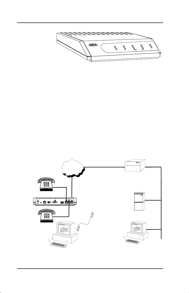
Single User to Corporate LAN
• Telecommuter/Home Office Access to the corporate LAN
• Single device access
• User Datagram Protocol (UDP) broadcasts are “relayed” to
corporate LAN.
• Client device can obtain the Internet Protocol (IP) address
dynamically using Dynamic Host Configuration Protocol
(DHCP).
• Compatible with popular central site LAN access devices
LINE
ISDN
Router
TO
HUBTONIC
1
O
OFF
ON
1234
21
EIA23210 BASE TPOWER
ISDN
Server
10 BT
10 BT
Figure 1-2. Single User to Corporate LAN
1-2 Express L128T S/T User Manual 61202070L3-20
Page 31

Chapter 1. Understanding ISDN and the Express L128T S/T
Single User IP to Internet Service Provider (ISP) using Network Address Translation (NAT)
• Provides high speed home access to the Internet
• NAT provides translation from user assigned IP addresses to an
ISP assigned IP address.
• The PC’s IP address can be dynamically assigned by the Express
L128T S/T by using DHCP.
• Overcomes the serial port speed limitations of current terminal
adapter solutions
• Multilink Point-to-Poin t Protocol (PPP) plus compression yields
effective throughput greater than 256 kbps depending on the
randomness and compressibility of the data.
• Compatible with popular ISP access devices
ISDN
TO
HUBTONIC
1
O
OFF
ON
1234
21
EIA23210 BASE TPOWER
ISDN
INTERNET
10 BT
10 BT
Figure 1-3 . Single User to Internet Se rvice Provider
61202070L3-20 Express L128T S/T User Manual 1-3
Page 32
Chapter 1. Understanding ISDN and the Express L128T S/T
Multiple Users to Internet Service Provider (ISP) using NAT
• Provides high speed home access to the Internet
• NAT provides translation from user assigned IP addresses to an
ISP assigned IP address.
• Multiple and simultaneous access
• The PC’s IP address can by dynamically assigned by the Express
L128T S/T using DHCP.
• On-demand Internet access
• Multilink PPP plus compression yields effective throughput
greater than 256 kbps depending on the randomness and
compressibility of the data.
• Compatible with popular ISP access devices
INTERNET
10 BT
TO
HUBTONIC
1
O
Hub
OFF
ON
1234
21
EIA23210 BASE TPOWER
ISDN
ISDN
Figure 1-4. Multiple User to Internet Service Provider
1-4 Express L128T S/T User Manual 61202070L3-20
Page 33

Chapter 1. Understanding ISDN and the Express L128T S/T
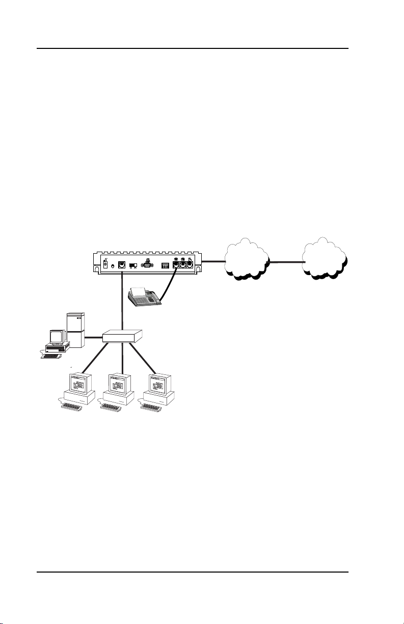
Small Office - Home Office (SOHO) to Corporate LAN
• Connects the small office or home office to the corporate LAN
• Routes IP and Internet Packet Exchange (IPX) traffic from
multiple devices to the corporate LAN
• Bridges all non-routed traffic (e.g., AppleTalk, NetBEUI, etc.)
• Provides dedicated or on-demand services
• Low-cost alternative to buying a high-end router
• Compatible with popular central site LAN access devices
10 BT
TO
HUBTONIC
1
O
Hub
OFF
ON
1234
21
EIA23210 BASE TPOWER
ISDN
ISDN
ISDN
Router
Server
Figure 1-5. SOHO to Corporate LAN
Basic Functions
The Express L128T S/T provides the following basic functions:
1. LAN Bridge: Bridging provides a point-to-point connection
between two LANs. The bridge learning function scans the
source and destination media access control (MAC) addresses of
all packets on its local LAN and determines which packets
should be transmitted over the ISDN link. Applications include
connectivity between single user or small offices to corporate
LANs. The Express L128T S/T uses the Spanning Tree
Algorithm (IEEE 802.1d-ISO/IEC10038), which provides a loopfree topology and redundancy.
61202070L3-20 Express L128T S/T User Manual 1-5
Page 34

Chapter 1. Understanding ISDN and the Express L128T S/T
2. IP Router: The Express L128T S/T can function as an IP router
using the Routing Information Protocol (RIP) for dynamically
advertising and learning routes among other routers. Static
routes may also be entered into the routing table.
3. IPX Router: IPX routers and services can be dynamica lly
exchanged between the Express L128T S/T and other devices
using RIP and Service Advertising Protocol (SAP). Wa tchdog
serialization filtering and spoofing can permit the ISDN to be idle
during no application traffic periods.
4. Network Address Translation (NAT): NAT allows a site to be
known to the Internet by one IP address. The IP addresses on the
LAN of the NAT router are private to the Internet. The IP
addresses (along with port numbers) are translated to the NAT
address that is assigned from the far-end router. NAT allows the
user to use only one IP address fro m the host site. While the LAN
of the NAT unit is hidden fro the Internet, a function called Webserver allows HTTP, FTP Telnet, and SMTP traffic to be directed
from the Internet to the hidden LAN network.
5. POTS: The POTS interfaces can be used for interfacing to dual
tone multi-frequency (DTMF ) analog d evices such as telephones,
modems, fax machines, etc. Progress tones can be pr ovided in µ-LAW
and A-LAW formats.
Demand Routing and Bridging with the Express L128T S/T
The Express L128T S/T is a dial-up ISDN IP Router and Transparent
Learning Bridge that provides Dial-On-Demand and Dynamic Bandwidth Management. Its features can be easily conf igured and used
once several basic concepts are understood.
Factory Default
The Express L128T S/T comes from the factory configured for MAC
Bridging, IP routing, and IPX routing with no filters or connection information defined. An IP address of 10.0.0.1 with a network mask of
255.255.255.0 is preloaded. Dynamic bandwidth management features
are disabled. Althoug h d y n a m i c a s signm ent of a B-ch a nnel f or the a n a log (POTS) ports on the Express L128T S/T model is always available,
1-6 Express L128T S/T User Manual 61202070L3-20
Page 35

Chapter 1. Understanding ISDN and the Express L128T S/T
link idle time-out and adding/removing of B-channels based on traffic is initially disabled.
Bridging
In Bridge Mode, the Express L128T S/T can communicate with two remote networks at a time. The destination is dialed by setting up a
Connection List profile and choosing Dial on the Dial menu. See Con-
figuration/Connection List on page 3-36 for instructions on setting up a
Connection List profile.
During a two B-channel PPP Multilink call, the Express L128T S/T automatically drops one B-channel and provides it to the POTS port
when a telephone call is placed or answered. When a POTS telephone
call terminates, the Express L128T S/T redials the second B-channel
and supplies the bandwidth back to the LAN connection. Since other
bandwidth management features are disabled in the factory default
configuration, the dialed links remain active until the Hang-up command is entered from the Dial menu, terminating the session with the
selected remote network.
The Connection List described in the next section may be used to automate dialing and to store additional information specific to the remote site being dialed (phone numbers, number of B-channels to dial,
authentication information, Caller ID, etc.). In addition, to re duce line
charges, Demand Dialing may be enabled to allow idle links to disconnect when not being used.
Simple Demand Bridging may be configured by enabling the Idle
Time-Out parameter under the Configuration/ Connection List [1]/
Bandwidth/On Demand option on the Connection List. Setting this
parameter to a non-zero value allows a bridge connection to disconnect after the specified number of seconds with no traffic crossing the
ISDN link. Bandwidth can be controlled using the Express L128T S/T’s
adv ance d f ilte rin g c apab ili ty. When new traffic needs to be transmitted,
the Express L128T S/T will run each packet through its Demand filters
defined for each Connection List profile. If a packet can pass through
the filter, then the numbers for that profile are dialed. In addition,
when both B-channels are selected for use, the link may be configured
to add/remove the second B-channel based on the amount of traffic
61202070L3-20 Express L128T S/T User Manual 1-7
Page 36

Chapter 1. Understanding ISDN and the Express L128T S/T
crossing the link. The bridged connection is terminated when the
Hang-up option is selected from the Dial menu, but will redial if the
demand filter condition is met.
IP Routing
The Express L128T S/T operates as a dial-up IP router when the Configuration/IP/IP Router/Mode option is configured to On. The Ex-
press L128T S/T uses an IP unnumbered WAN interface; the IP
address and mask assigned to the unit’s LAN interface apply to all
routing and IP operations for the unit. If a default gateway is specified
on the network of the Ethernet interface, the unit attempts to reach the
gateway through that interface. If the gateway is specified on an unknown network, the unknown network is assigned to the router table
and remains unused until that gateway becomes the peer on a WAN
connection. If no default gateway is specified, the first connected peer
on the WAN interface becomes the default gateway (recommended
for remote applications when there are no other routers on the remote
LAN).
For each profile in the Connection List that includes an IP address and
has the Configuration/Connection List/IP/Route/Static Route option
set to Yes, the Network Address of the specified IP address is added
to the router table with the Host Address as the gateway. If the Con-
figuration/Connection List/IP/Route/Private option is set to No, the
route is advertised at the specified metric through the unit’s interfaces
as if a connection is active to that network. These routes are referred
to as spoofed routes.
Attempts by any computer connected to the LAN interface to access a
host on a spoofed network causes a connection to be attempted using
the information from that Connection List profile. Once connected,
routes advertised by the peer router are learned and advertised to the
local LAN. If Bandwidth-On-Demand is enabled and an Idle Timeout value is specified, expiration of the Idle Timer causes the link to be
disconnected; the routes learned from the peer router are retained if
the Configurat ion/Connection List/IP/RIP/Retain option is set to Yes
and advertised as if the connection is still active. These routes are referred to as retained routes. Attempts by any connected co mputer to access a host on any of the retained routes causes the link to be redialed.
1-8 Express L128T S/T User Manual 61202070L3-20
Page 37

Chapter 1. Understanding ISDN and the Express L128T S/T
If Han g Up is activated from the Dial menu when the link is dow n, the
retained routes are removed.
The Express L128T S/T can be connected to two WAN destinations at
the same time. Each B-channel is dialed to a different location. Routes
learned from one WAN destination are advertised to the other using
RIP.
IPX Routing
Like IP routing, the Express L128T S/T can connect to two different
sites and exchange IPX packets. Network routes and services are
learned and advertised using Novell’s RIP and SAP. Routes and services learned from a separate site can be retained in the Express L128T
S/T when the connection goes idle. While retained, the Express L128T
S/T can spoof RIP/SAP and watch-dog and filter serialization packets
that would normally be required between the Novell server and client.
Connection List - Simplifying and Enhancing the Dial Function
The Connection List, which is accessed from the Conf iguration menu,
provides a location to define information regarding 15 individual destinations that may be dialed. A Connection List entry is required for
each destination since authentication information (m ethod, username,
password), number of B-channels, telephone numbers, Caller ID, IP,
or IPX address (for routed connections), and other info rmation can be
stored for each destination defined. Defined destinations may be dialed by selecting the Dial activator in the Dial menu or by demand for
the desired Connection List profile.
Concurrent Routing and Bridging
The Express L128T S/T can route IP and IPX as well as bridge non-IP/
IPX packets simultaneously. The Connection List profile will by default negotiate PPP network protocols to support the transmission and
reception of IP, IPX, and Bridge packets. If the PPP peer does not accept a protocol, the Express L128T S/T will fall back to any combination of routing and bridging.
61202070L3-20 Express L128T S/T User Manual 1-9
Page 38

Chapter 1. Understanding ISDN and the Express L128T S/T
Routing over PPP Bridging
The Express L128T S/T can support legacy equipment which does not
support PPP IP (IPCP) or IPX (IPXCP) protocols by all owing routing
packets over the WAN connection using PPP Bridging (BCP). To perform this, the Express L128T S/T uses a “virtual” Ethernet port. This
port is set up under the Configuration/Bridge menu.
This feature identifies the calling party number for incoming
calls. This feature may not be functional for all countries or if
calling party information is not supplied by the central office
switch.
Network Address Translation Mode
NAT is a special mode of operation in which the Express L128T S/T
obtains a dynamically assigned IP address from the peer router (typically an Internet Service Provider). This allows a network of computers to benefit from Ethernet to ISDN speeds while still appearing to
the Internet Service Provider (or central site router) as a single IP address, which is typical of PC based serial dial-up solutions.
A call is initiated to the ISP using the Dial menu or demand for a Connection List profile that has the IP parameter NAT set to Yes. The network computer’s IP stack may use DHCP to request an IP address,
default gateway address, and domain name server addresses from the
Express L128T S/T.
1-10 Express L128T S/T User Manual 61202070L3-20
Page 39

Chapter 1. Understanding ISDN and the Express L128T S/T
Front P anel
Figure 1-6 on page 1-11 shows the front panel of the Express L128T S/T.
The indicators are divided into LAN, WAN, and Test functions.
LAN Indicators
TX/RX
Flashes green when transmitting data onto the 10BaseT
connector. Flashes yellow when receiving data from the
10BaseT connector.
LI
Link integrity. Illuminates when there is a good connection
between the Express L128T S/T and the Hub/NIC card.
WAN Indicators
PWR
B1
B2
Flashes when the link is deactivated or disconnected; solid
when the link is active.
Flashes green when the link is being negotiated; off when
the link is active. After the link is active, B1 flashes green
when a call on B1 channel is in prog ress; s olid green when
a call is connected.
Flashes green when the link is being negotiated; off when
the link is active. After the link is active, B2 flashes green
when a call on B2 channel is in progress; solid green when
a call is connected.
Test Indicators
B1/B2
A slow amber flash indicates test in progress; a fast amber
flash indicates test has failed.
TX/RX B1 B2 PWR
EXPRESS L128T
LI
TEST
LINE
Figure 1-6. Express L128T S/T LEDs
61202070L3-20 Express L128T S/T User Manual 1-11
Page 40

Chapter 1. Understanding ISDN and the Express L128T S/T
Rear Panel
The Express L128T S/T has one RJ-45 jack, labeled ISDN, on the rear
panel for network connection (see Figure 1-7). There are two sets of
switches on the back panel. The TO HUB/TO NIC switch allows the
Express L128T S/T to connect directly to a Network Interface Card
(NIC) or a HUB without the need for special cabling. The OFF/ON
switch block is for factory default, firmware downloading, S/T bus
termination, and A-LAW/µ-LAW Pots tone selection. With switch 1
in the up or OFF position, the L128T S/T will go immediately into a
download mode when power is enabled. Switch 1 must be in the
down or ON postition in order to boot up normally. Switch 2 in the up
or OFF position will force the entire configuration to be f acto r y defaulted. Switch 3 must be up or in the OFF position to disable passive
bus (enable 100 π termination). Switch 4 must be up or in the OFF position to disable µ-Law (enable A-LAW).
TO
1
O
HUBTONIC
OFF
ON
EIA23210 BASE TPOWER
1234
21
ISDN
1202070L3
Figure 1-7. Express L128T S/T Rear Panel
ISDN Connection
From the network, ISDN is delivered by a single 4-wire S/T interface
which is connected directly to the Express L128T S/T. 100 ohm termination resistors can be enabled for point-to-point application and disabled for passive bus applications via a dip swi tch on the rear panel.
The Express L128T S/T has one RJ-45 jack, labeled ISDN, o n the rear
panel for network connection (see Figure 1-7). ISDN basic rate service
divides a standard telephone line into three digital channels capable
of simultaneous voice and data transmission. The three channels are
comprised of two bearer (B) channels at 64 kbps and one Delta (D) or
Signalling channel at 16 kbps, known as 2B+D.
1-12 Express L128T S/T User Manual 61202070L3-20
Page 41

Chapter 1. Understanding ISDN and the Express L128T S/T
The Express L128T S/T also supports a leased digital connection allowing data to be transferred at up to 128 kbps over a 4-wire facility
using the same RJ-45 jack. This type of service is a permanent co nnection between endpoints and is sometimes referred to as a leased connection, a dedicated connection, a nailed-up connection, or a private
circuit. Leased connection or leased line is used in th is manual to represent these types of services.
Interoperability
The Express L128T S/T is standards based and uses PPP developed by
Internet Engineering Task Force (IETF). PPP provides a standard
method of transporting multiprotocol datagr ams over point-to-point
links. PPP is widely accepted by many ISDN bridge/router ma nufacturers. The Express L128T S/T will negotiate Multilink PPP when
connecting both B-channels. The Bandwidth Allocation Protocol
(BAP) may also negotiate, which enhances the management of adding
and removing a B-channel. Data compression is also supported using
®
LZS
technology from hi/fn™.
Connecting to the Internet
Internet Service Providers (ISPs) assign an IP address to use when connected to their service using PPP negotiation. This assignment is
based on the assumption that the user has an ISDN terminal adapter
running PPP async-to-sync conversion or another rate adaption where
the PPP negotiation is terminated inside the PC’s IP stack. However,
if an ISDN-Ethernet gateway device is used, the ISP must preassign
the customer a subnet which uses multiple IP addresses. This may result in a much higher cost to the user.
The Express L128T S/T permits the user to assign any IP address to
the unit and computers. Operations on the network ca n occur normally. In fact, one B-channel can connect to the ISP using NAT while the
other B-channel connects to another “private” or “fake” network. All
packets transmitted or received over the ISP connection are translated.
The Express L128T S/T keeps track of the computers that request services over the Internet. A web server address can be assigned under
the Configuration/IP/NAT menu that allows incoming HTTP, FTP,
61202070L3-20 Express L128T S/T User Manual 1-13
Page 42

Chapter 1. Understanding ISDN and the Express L128T S/T
and mail server requests from the Internet to be translated and forwarded to this address on the user network.
Configuration
The Express L128T S/T is configured using a menu-based interface.
This interface can be accessed via the maintenance port using any
asynchronous VT 100 terminal or personal computer running a terminal emulation program, or via the LAN using a Telnet client program.
To use the Telnet interface, the Express L128T S/T must first have an
IP address programmed into it via the maintenance port. The factory
default is 10.0.0.1.
Security
Security on network devi ces is a major concern for almost an yone with
a network. The Express L128T S/T provides many tools for securing
the local network from hostile users . Incoming calls can be authenticated using passwords and Caller ID.* A RADIUS client can also be
used.
The Telnet configuration can also be protected using the same authentication methods. Each menu item in the Express L128T S/T has a security level associated with it. A Telnet session is assigned a privilege
level which determines which menu items are accessible to the Telnet
client. See Security Levels on page 3-7 (in Chapter 3) for more information on menu security levels.
Filters can be defined to prevent certain addresses or protocols from
being transferred from LAN-to-WAN, WAN-to-LAN, or WAN-toWAN.
*This feature identifies the calling party number for incoming
calls. This feature may not be functional for all countries or if
calling party information is not supplied by the central office
switch.
1-14 Express L128T S/T User Manual 61202070L3-20
Page 43

Chapter 2
Installation
SHIPPING DAMAGE
After unpacking the unit, immediately inspect it for possible shipping
damage. If damage is discovered, file a claim immediately with the
shipping carrier; then contact the ADTRAN Repair and Return department.
ISDN NETWORK CONNECTION
The Express L128T S/T supports either dial or leased operation. A
single RJ-45 modular jack labeled ISDN on the rear panel provides
connection to either network service.
Dial operation allows the user to dial out or receive calls over the public network. The leased operation mode supports dedicated data service at rates up to 128 kbps by using a nailed up circuit, or a permanent
connection between endpoints.
See Connector Pinouts on page D-1 for ISDN network connector pin assignments.
LOCAL AREA NETWORK CONNECTION
The Express L128T S/T has a 10BaseT connector that provides halfduplex 10 Mbps operation over a 4-wire twisted pair. Place the switch
in the TO HUB position when connecting to a 10BaseT concentrator o r
Hub. Place the switch in the TO NIC position when connecting directly to a computer’s 10BaseT network interface card.
Other types of Ethernet interfaces (i.e., AUI, 10Base2, etc.) can be accommodated by obtaining an appropriate converter.
61202070L3-20 Express L128T S/T User Manual 2-1
Page 44

Chapter 2. Installation
TELEPHONE CONNECTION
Basic Telephone Service
The Express L128T S/T supports an analog DTMF telephone type
(AT&T 2500) with the POTS interface. Two telephones or other analog
devices (like a fax machine or modem) plug into either RJ-11 jack (labeled with drawings of telephones) on the rear of the unit. Progress
tones can be generated in A-LAW or µ-LAW format.
Supplementary Services
Supplementary services such as call holding, three- or six-way co nferencing, call transfer, and call waiting are fully supported by the Express L128T S/T on a touch-tone telephone. Table 2-1 on page 2-3
explains how the flash-hook is used for handling multi-call situations.
Supplementary services are not supported for all countries.
DTMF Keypad
The following functions are performed on a touch-tone phone:
Disable call waiting: Press
Enable call waiting: Press
Redial last number: Press
Enter Phone Number 1: Press
Enter Phone Number 2: Press
2-2 Express L128T S/T User Manual 61202070L3-20
**0
**1
**5
**8XXXXXXX*
XXXXXXX is the phone number.
The terminal * indicates end of digits.
**9XXXXXXX*
XXXXXXX is the phone number. If only
one phone number is assigned, this
does not have to be entered.)
The terminal * indicates end of digits.
(where
(where
Page 45

Chapter 2. Installation
Table 2-1.
Using the Flash-Hook
Calling a second party with an active call:
Flash-hook to place active call on hold and dial new number.
Hanging up will terminate the call.
Answering an incoming call with an active call at call
waiting:
Flash-hook to place active call on hold and answer incoming call.
Hanging up will terminate both calls.
Conferencing Calls:
With an outgoing call on hold, and a second outgoing call active,
flash-hook to conference calls. Hanging up will transfer second call.
With an incoming call on hold, and outgoing call active, flash-hook to
conference calls. Hanging up will transfer calls.
With two incoming calls (one on hold and one active) flash-hook to
conference calls. Hanging up transfers calls.
Answering calls on hold, and holding incoming active
calls:
Flash-hook places the incoming call on hold and reconnects to
outgoing call. Hanging up will terminate both calls.
Customer Premises Wiring
Customer premises wiring requirements for the Express L128T S/T
vary depending on the application and existing wiring. It may be simpler for the ISDN provider to deliver another line to your location.
This would eliminate the need to modify existing wiring. Figures 2-1
on page 2-4 and 2-2 on page 2-5 illustrate two wiring scheme possibilities.
61202070L3-20 Express L128T S/T User Manual 2-3
Page 46
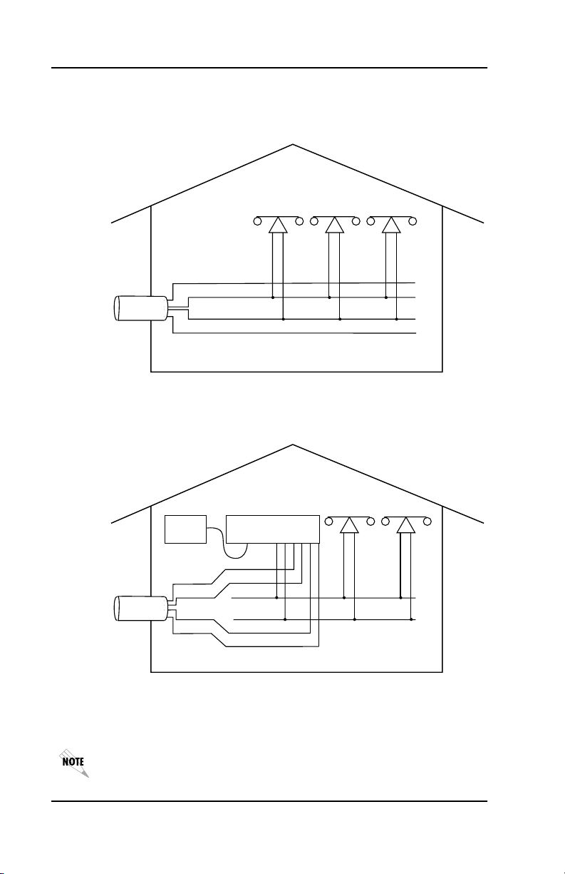
Chapter 2. Installation
To
Telephone
Company
Current Wiring Scheme
Yellow
Red
Green
Black
New Wiring Scheme
Express L128T S/T
10-Base-T Phone S/T
To
Telephone
Company
Personal
Computer
Yellow
Red
Green
Black
Figure 2-1. Wiring Scheme 1
Use existing analog telephone equipment, but replace single analog
telephone service with ISDN service.
The S/T interface requires a 4-wire connection.
2-4 Express L128T S/T User Manual 61202070L3-20
Page 47
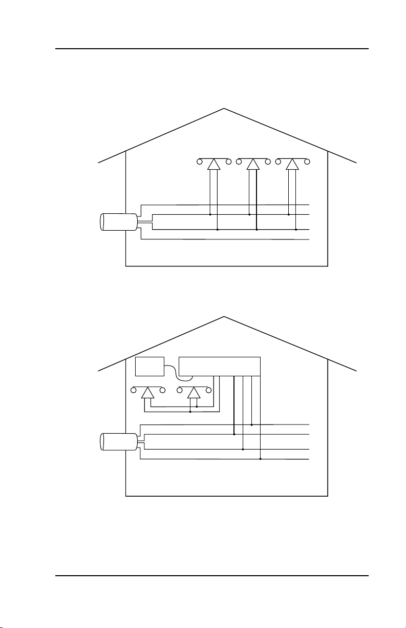
To
Telephone
Company
Chapter 2. Installation
Current Wiring Scheme
Yellow
Red
Green
Black
New Wiring Scheme
Express L128T S/T
10-Base-T Phone
Red Green
W A R N I N G
S/T
To
Telephone
Company
Personal
Computer
Yellow
Red
Green
Black
Ensure other yellow and black wire functions are removed
before using this wiring scheme.
Figure 2-2. Wiring Scheme 2
Retain single analog telephone service and add ISDN service.
61202070L3-20 Express L128T S/T User Manual 2-5
Page 48

Chapter 2. Installation
2-6 Express L128T S/T User Manual 61202070L3-20
Page 49

Chapter 3
Terminal Menu Operati on
TERMINAL MENU STRUCTURE
The Express L128T S/T uses a multilevel menu structure containing
both menu items and data fields. All menu operations and data display in the terminal menu window. The Express L128T S/T is shipped
in the Factory Default configurat ion. Connect any VT 100 or VT 220
type terminal emulator to the maintenance port with a straightthrough RS-232 cable. The default rate is 9600 baud 8-N-1. The terminal emulator can flow the Express L128T S/T off using software flow
control. Hardware flow control is not used.
The opening menu (the Main menu, or top-level menu) is the acc ess
point to all other operations. Each Main menu item has several functions and submenus to identify and access specific parameters. Top
Level Terminal Menu on page 3-2 shows the top-level terminal menu.
The Main menu options are described in the following pages.
In order to edit items in the terminal menus, you must have the
appropriate security level. Each menu description in this section
indicates the required security level required for writ e access.
The maintenance port is always at security level 0, giving full
access to all configuration items.
61202070L3-20 Express L128T S/T User Manual 3-1
Page 50
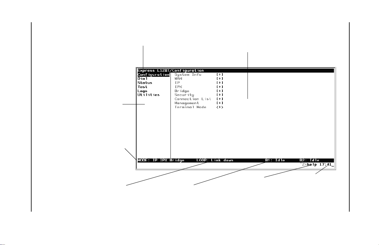
3-2 Express L128T S/T User Manual 61202070L3-20
Left Pane
Figure 3-1. Top Level Terminal Menu
Lists available menus.
Mode
Describes current operating mode.
Menu Path
Describes the current position in
the terminal menu structure.
Right Pane
Chapter 3. Terminal Menu Operation
Lists available submenus. Additional submenus
available through thi s pane are indicated by the
[+] and [DATA] symbols.
Loop Status
Displays current status of
ISDN line.
B-channel Status
Displays current status of
each B channel.
Navigation Help
Displays list of characters you can us e to navigate the terminal menus.
Control-Z
Press
.
System Time
Displays the current
time. See
Date/Time
on page 3-9 for details
on setting the time.
Page 51

Chapter 3. Terminal Menu Operation
Configuration
The Configuration menu provides options to set up the operational
configuration for the Express L128T S/T. See the section Configuration
Menu on page 3-8 for detailed information.
Dial
The Dial menu is used to connect to different sites based on the Connection List. See the section Dial Menu on page 3-64 for more details.
Status
The Status menu provides options to review and monitor the status of
the Express L128T S/T system. See the section Status Menu on page 366 for detailed information on the available options.
Test
The Test menu can be used for performin g diagnostic testing of the Express L128T S/T. See the section Test Menu on page 3-74 for detailed
information on the tests avail able.
Logs
The Logs menu can be used for viewing the operational logs for the
Express L128T S/T. See the section Logs Menu on page 3-75 for detailed information on the avai lable options.
Utilities
The Utilities menu provides tools for system diagnostics and upgrading the Express L128T S/T. See the section Utilities Menu on page 3-79
for detailed information on the available options.
61202070L3-20 Express L128T S/T User Manual 3-3
Page 52

Chapter 3. Terminal Menu Operation
NAVIGATING THE TERMINAL MENUS
The following sections provide inform ation on how to navigate
through the terminal menus.
General Layout
When you first start a terminal mode sess ion, the window shown in
Top Level Terminal Menu on page 3-2 displays. The screen is divided
into left and right panes. The left pane shows the current list of submenus, while the right pane shows the contents of a selected submenu.
Menu Path
The top line of the display shows this session’s current position (path)
in the menu tree. Figure 3-1 shows the top menu level with the cursor
on the Configuration submenu, so the path display sh ows Express
L128T/Configuration.
Moving Around
Press Tab or the right arrow key to move the cursor from the left pane
to the right pane. Press Shift+Tab or press the left arrow key to move
the cursor from the right pane back to the left pane. Use the up and
down arrows to move around within each pane. Press Enter to activate a menu. Press the left arrow key or the Escape key to go back up
the menu. The following options display throughout the menus.
Submenus [+] or [DATA]
Menus that display [+] or [DATA] indicate that more items are available when selected.
Activation Field <+>
Menus that display <+> indicate that an action is to be taken , such as
activati n g a test.
3-4 Express L128T S/T User Manual 61202070L3-20
Page 53

Chapter 3. Terminal Menu Operation
Editable Data Field
A highlighted menu item indicates that you can enter data in that
field.
Read-Only Field
An underlined field is a display field that contains read-o nly information.
Navigation with the Keyboard
You can use different keystrokes to navigate through the terminal
menu. Press Control-Z to activate a pop-up screen with the available
keystrokes. The following section provides a list of the available keystrokes and the results:
General Navigation
H
J
Arrow Keys
Enter
Escape
Tab and
Shift+Tab
A
Z
Backspace
Returns to the home screen.
Jumps between two menu items. Press J while on a menu
item of interest, and you will jump back to the main screen.
Go to another menu item of interest, press J, and you will
jump back to the screen that was displayed the first time you
pressed J. Press J anytime you want to jump between these
items.
Selects items and moves between the left and right panes.
The left arrow key allows you to go back up the menu.
Activates an item or moves into submenu.
Cancels an edit. Allows you to go back up the menu. Also
will dismiss the pop-up help screens.
Moves between the left and right panes.
Moves to the top of a screen.
Moves to the bottom of a screen.
Ascends one menu level.
61202070L3-20 Express L128T S/T User Manual 3-5
Page 54

Chapter 3. Terminal Menu Operation
Session Management
Control-L
Control-S
Logs out of the session.
Invalidates the password entry and returns to the log in
screen. The Password prompt will display.
Control-R
Refreshes the screen. To save time, only the portion of the
screen that has changed is refreshed. This option should be
necessary only if the display picks up incorrect characters.
Configuration
F
Restores factory default settings. This setting restores the
factory defaults based on the location of the cursor. Entire
submenus can be factory defaulted.
C
Copies selected items to the clipboard. The amount of
information you can copy depends on the cursor location
when you press C. For example, if the cursor is over an
editable field, only that item is copied. If the cursor is over
the index number of a list, then all of the items in the row of
the list are copied. For example, if the cursor is over the
Num
field in the Connection List screen, all of the
information associated with the Connection List entry is
copied.
P
Pastes the item stored in the clipboard, if the information in
compatible. You must confirm all pastes except those to a
single editable field.
>
For certain types of fields, when you paste information into
the field, the value increments by 1.
<
For certain types of fields, when you paste information into
the field, the value decrements by 1.
I
Inserts a new item in a list. For example, add a new item to
the Connection List by pressing I while the cursor is over the
index number.
D
Deletes a list item. For example, delete an item from the
Connection List by pressing D while the index number is
active.
3-6 Express L128T S/T User Manual 61202070L3-20
Page 55

Chapter 3. Terminal Menu Operation
Security Levels
Each menu item on the configuration screens has an associated security level. The security level ranges from 0 (highest security level) to 5
(lowest security level). This level determines whether a Telnet session
can access that menu item. The Telnet session is assigned a security
level set by the user. Passwords can only be accessed as security level
0. The maintenance port is always at security level 0.
The security levels are assigned as follows:
Level Description
0
Access all parameters including passwords
1
Access all parameters except passwords
2
Access all parameters except passwords and authentication
methods
3
Access all parameters except passwords, authentication
methods, and ISDN parameters
4
Access only test and status menus
5
Access status menus only
61202070L3-20 Express L128T S/T User Manual 3-7
Page 56

Chapter 3. Terminal Menu Operation
CONFIGURATION MENU
Configuration/System Info
The System Info menu provides basic information about the unit and
displays data fields for editing information. Figure 3-2 displays the
submenus available under this menu item.
Figure 3-2. Configuration/System Info Screen
System Name
Write security: 3; Read security: 5
Provides a user configurable text string for the name of the Express
L128T S/T. This name can help distinguish between different installations. You can enter up to 31 alpha-numeric characters in this field,
including spaces and special characters (such as an under bar). The
system name is also used for PPP authentication and IPX service
name.
3-8 Express L128T S/T User Manual 61202070L3-20
Page 57

Chapter 3. Terminal Menu Operation
System Location
Write security: 3; Read security: 5
Provides a user configurable text string for the location of the Express
L128T S/T. This helps to keep track of the physical locatio n o f the
unit. You can enter up to 31 alpha-numeric characters in this field, including spaces and special characters (such as an under bar).
System Contact
Write security: 3; Read security: 5
Provides a user configurable text string for the contact name. This
field can contain a name, phone number, or e-mail address of a person
responsible for the Express L128T S/T. You can enter up to 31 alphanumeric characters in this field, including spac es and special characters (such as an under bar).
Firmware Revision
Read security: 5
Displays the current firmware revision level of the Express L128T S/T.
This field is a read-only field.
System Uptime
Read security: 5
Displays the length of time the Express L128T S/T has been running
since power up or reset. This field is a read-only field.
Date/Time
Write security: 3; Read security: 5
Displays the current date and time as programmed in the real time
clock. This field can be edited. Enter the time in 24-hour format (such
61202070L3-20 Express L128T S/T User Manual 3-9
Page 58

Chapter 3. Terminal Menu Operation
as 23:00:00 to represent 11:00 PM). Enter the date in mm- dd-yyyy format (for exam ple, 09-30-1998).
Configuration/WA N
The WAN menu is used to set up the ISDN and POTS parameters for
the Express L128T S/T. Figure 3-3 shows the WAN menu.
Figure 3-3. Configuration/WAN Screen
WAN/ISDN
Write security: 2; Read security: 5
Selects the mode the ISDN line is in. If connecting to the public network, select Dial (def). If connecting to a leased wire for back-to-back
operation, select Leased.
ISDN/Dial Line
Dial Line parameters are entered under this menu.
3-10 Express L128T S/T User Manual 61202070L3-20
Page 59

Chapter 3. Terminal Menu Operation
Dial Line/Switch Protocol
Write security: 2; Read security: 5
Find out what kind of ISDN switch protocol the local CO is
using by asking the local telephone administrator or the telephone company representative. The Express L128T S/T can be
configured for the following:
LUCENT 5ESS
NEC, TDX10
EURO ISDN, TDX1B
(def) LUCENT 5ESS© Custom
Nippon Electric Company Switch
NET3 or similar
Dial Line/Area Code
Write security: 2; Read security: 5
Enter 3-digit area code when using ExpertISDN.
Dial Line/Local Number 1 or 2
Write security: 2; Read security: 5
This option allows the entry of 0, 1, or 2 Local Numbers. The
Local Number is used when placing or receiving calls. The Local
Number is the local phone number assigned to the line.
Local Number 1 = 5 5 5 1 2 1 2
Local Number 2 = 5 5 5 1 2 1 3
ISDN/Leased Line
Write security: 2; Read security: 5
Leased Line parameters are entered under this menu. Leased mode
would be used for permanent circuits.
Leased Line/Channel Rate
Write security: 2; Read security: 5
64k
2x64k
128k
(def) B1 and B2 are used together.
61202070L3-20 Express L128T S/T User Manual 3-11
Only B1 is used.
B1 and B2 go to different locations.
Page 60

Chapter 3. Terminal Menu Operation
WAN/POTS
Write security: 2; Read security: 5
POTS parameters are under this menu.
POTS/POTS Assignment
Write security: 2; Read security: 5
The Express L128T S/T can assign the POTS interface either POTS1 to
LDN 1 and POTS2 to LDN 2 (def), or POTS2 to LDN 1 and POTS1 to
LDN 2 . Once assigned, all incoming and outgoing calls on a particular
port are placed to/from the assigned number.
POTS/Speech Calltype Routing
Write security: 2; Read security: 5
This allows the Express L128T S/T to treat incoming calls as “data
over voice" (DOV) when selected as LAN. Otherwise, when set to
POTS (def), incoming speech calls are sent to the POTS when the destination number is the same as the POTS assignment.
3-12 Express L128T S/T User Manual 61202070L3-20
Page 61

Chapter 3. Terminal Menu Operation
Configuration/IP
The IP menu is used to set up the IP parameters for the Express L128 T
S/T. Any general IP-related configuration item is under this menu.
Figure 3-4 shows the IP menu.
Figure 3-4. Configuration/IP Screen
IP/IP Address
Write security: 2; Read security: 5
The IP address assigned to the Express L128T S/T’s Ethernet port is
set here. This address must be unique within the network. Factory default is 10.0.0.1.
IP/Subnet Mask
Write security: 2; Read security: 5
The IP network mask to be applied to the Express L128T S/T’s Ethernet port is set here. Factory default is 255.255.255.0.
61202070L3-20 Express L128T S/T User Manual 3-13
Page 62

Chapter 3. Terminal Menu Operation
IP/Default Gateway
Write security: 3; Read security: 5
The default gateway is used by the Express L128T S/ T for sen ding IP
packets whose destination address is not found in the route table. If
this address is all zeros, then the first WAN connection becomes the
default gateway. If the address entered is not on the Ethernet segment, then an “idle route” entry is added to the route table.
IP/Static Routes
Static Routes can be inserted under this menu.
Static Routes/Active
Write security: 4; Read security: 5
Adds this static route entry to the IP routing table when set to Yes (def)
and removes it (if it was previously added) if set to No.
Static Routes/IP Address
Write security: 4; Read security: 5
This is the IP address of the host or network address of the network.
Static Routes/Subnet Mask
Write security: 4; Read security: 5
This mask determines the bits in the previous IP address that are used.
If this is to be a host route, it must be set to all ones (255.255.255.255).
Static Routes/Gateway
Write security: 4; Read security: 5
This is the IP address of the router to receive the forwarded IP packet.
3-14 Express L128T S/T User Manual 61202070L3-20
Page 63

Chapter 3. Terminal Menu Operation
Static Routes/Hops
Write security: 4; Read security: 5
This is the number of router hops required to get to the network or
host. Maximum distance is 15 hops.
Static Routes/Private
Write security: 4; Read security: 5
When set to No, the Express L128T S/T will advertise this static route
using RIP. Otherwise, setting to Yes means that the route is kept private.
IP/IP Router
The IP router is configured under this menu as follows.
IP Router/Mode
Write security: 3; Read security: 5
When this option is set to On (def), the Express L128 T S/T will advertise and listen to routes from other IP routers. If Off, the route table is
still used but only static routes are used for routing IP packets and
only the Ethernet port is used. IP packets can be sent over the WAN,
but only when bridged.
IP/RIP
Write security: 3; Read security: 5
The Routing Information Protocol (RIP) is supported by the Express
L128T S/T. The following parameters are required for setting up the
mode on the Ethernet port:
RIP/Mode
Write security: 3; Read security: 5
This option turns RIP On (def) or Off.
61202070L3-20 Express L128T S/T User Manual 3-15
Page 64

Chapter 3. Terminal Menu Operation
RIP/Protocol
Write security: 3; Read security: 5
Version can be V1 (def) or V2.
RIP/Method
Write security: 3; Read security: 5
Split Horizon
Poison Reverse
None
All routes are advertised, including
Only routes not learned on the Ethernet
port are advertised.
(def) All routes are advertised, including
routes learned from the Ethernet port.
These routes are poisoned.
routes learned from the Ethernet port.
No attempt is made to poison these
routes.
RIP/Direction
Write security: 3; Read security: 5
Tx and Rx
Tx only
Rx only
(def) RIP advertisements are transmitted and
listened to on the Ethernet port.
RIP advertisements are transmitted and
not listened to.
RIP advertisements are listened to but not
transmitted.
RIP/V2 Secret
Write security: 0; Read security: 0
This is a text string used for authenticating advertised routes.
IP/NAT
The Network Address Translation general parameters are set up under this menu.
3-16 Express L128T S/T User Manual 61202070L3-20
Page 65

Chapter 3. Terminal Menu Operation
NAT/DHCP Mode
Write security: 3; Read security: 5
When this option is set to On, the Express L128T S/T acts as a DHCP
server and will dynamically assign IP, network mask, default gateway, and DNS addresses to any device which transmits a broadcast
DHCP request. The addresses assigned are based on the Express
L128T S/T’s own IP address and will be within the same network.
This mode is most commonly used with the NAT functionality. The
default is Off.
NAT/DHCP Renewal Time
Write security: 3; Read security: 5
This is the number of hours that the DHCP server should allow the device before it is required to send a new DHCP request. The default is
15 hours, and 0 represents an infinite lease.
NAT/Web Server
Write security: 3; Read security: 5
This is the IP address of a web server on the Ethernet network. When
an active NAT connection is made to the Internet, any HTTP, FTP, or
Mail server requests from the WAN are translated and sent to this web
server.
IP/DNS
The Domain Name Server parameters used by the Express L128T S/ T
are specified here. The DNS server addresses can be exchanged between PPP peers. When a connection occurs and IPCP is negotiated,
the Express L128T S/T will get the DNS server addresses from the PPP
peer. If the configured DNS server addresses (Server 1 and Server 2)
are all zeros, the addresses from the PPP peer are used. In NAT mode,
the PPP peer’s DNS addresses are always used. The DNS addresses set
in Server 1 and Server 2 are offere d to a PPP peer if so requested.
61202070L3-20 Express L128T S/T User Manual 3-17
Page 66

Chapter 3. Terminal Menu Operation
DNS/Domain Name
Write security: 3; Read security: 5
This is a text string used to represent the domain name used by the Express L128T S/T.
DNS/Server 1
Write security: 3; Read security: 5
This is the IP address for the primary DNS device. It is the first server
that domain name requests are sent.
DNS/Server 2
Write security: 3; Read security: 5
This is the IP address for the secondary DNS device. It is used as a
back-up in case the primary address does not respond to the request.
IP/UDP Relay
The Express L128T S/T can be configured as a relay agent for UDP
broadcast packets. Normally, a router will not forward UDP broadcast packets. However, many network applications use UDP broadcasts to configure addresses, host names, and other information. If
hosts using these protocols are not on th e sam e network segment as
the servers providing the information, the client programs will not receive a response without enabling the UDP relay agent.
UDP Relay/Mode
Write security: 3; Read security: 5
When this option is set to On (def), the Express L128T S/T will act as
a relay agent.
3-18 Express L128T S/T User Manual 61202070L3-20
Page 67

Chapter 3. Terminal Menu Operation
UDP Relay/UDP Relay List
Up to four relay destination servers can be specified in this list.
UDP Relay List/Relay Address
Write security: 3; Read security: 5
This is the IP address of the server that will receive the relay
packet.
UDP Relay List/UDP Port Type
Write security: 3; Read security: 5
Standard
Specified
(def) The following standard UDP protocols are
relayed when set: DHCP, TFTP, DNS, NTP
(Network Time Protocol, port 123). NBNS
(NetBIOS Name Server, port 137), NBDG
(NetBIOS Datagram, port 138), and BootP.
When set, the UDP port (1 to 65535) can be
specified in the UDP Port columns. (up to a
maximum of three per server).
UDP Relay List/UDP Port 1, UDP Port 2, UDP Port 3
Write security: 3; Read security: 5
UDP Port 1, UDP Port 2, and UDP Port 3 are used for specifying
UDP ports to be relayed. These fields only apply when UDP
Port Type is set to Specified.
IP/Proxy ARP
Write security: 4; Read security: 5
This feature allows the network portion of a group of addresses to be
shared between several physical network segments. The ARP protocol
itself provides a way for devices to create a mapping between physical
(i.e., Ethernet) addresses and logical IP addresses. Proxy ARP makes
use of this mapping feature by instructing a router to answer ARP requests as a “proxy” for the IP addresses behind one of its ports. The
device which sent the ARP request will then correctly assume that it
can reach the requested IP address by sending packets to the physical
address that was returned to it. This technique effectively hides the
61202070L3-20 Express L128T S/T User Manual 3-19
Page 68

Chapter 3. Terminal Menu Operation
fact that a network has been (further) subnetted. If this option is set to
Yes (def), when an ARP request is received on the Ethernet port the
address is looked up in the IP routing table. If the forwarding port is
not on the Ethernet port and the route is not the default route, the Express L128T S/T will answer the request with its own hardware address. If set to No, the Express L128T S/T will only respond to ARP
requests received for its own IP address.
Configuration/IPX
The IPX menu is used to set up the IPX parameters for the Express
L128T S/T. Any general IPX-related con figuration item ca n be foun d
under this menu. Figure 3-5 shows the IPX menu.
Figure 3-5. Configuration/IPX Screen
IPX/Mode
Write security: 2; Read security: 5
When this option is set to On (def), the Express L128T S/T will route
IPX. Setting it to Off will disable all IPX fun c tionality.
3-20 Express L128T S/T User Manual 61202070L3-20
Page 69

Chapter 3. Terminal Menu Operation
IPX/Network
Write security: 2; Read security: 5
The IPX network address for the Ethernet port is set here. This is an
eight-digit hexadecimal value that uniquely identifies the network
segment of the Ethernet port. Accidental selection of an IPX n etwork
which is already in use on another network segment may cause hardto-diagnose problems. IPX network numbers sho uld be carefully
tracked.
IPX/Frame Type
Write security: 2; Read security: 5
The Express L128T S/T supports all four de fined IPX frame types. The
possible frame types are: Ether Type II (def), Ether 802.3 (Raw), Ether
802.2, or Ether SNAP (802.2 SNAP). Only on e frame type can be used
at one time.
61202070L3-20 Express L128T S/T User Manual 3-21
Page 70

Chapter 3. Terminal Menu Operation
IPX/Seed Status
Write security: 2; Read security: 5
The seed status defines what the Express L128T S/T is to do with the
network information on the selected frame type during startup. There
are three possible seeding selections specified:
Seed
Non-Seed
(def)
Auto-Seed
The Express L128T S/T will listen for an IPX network
number being sent by another router (including Novell
software routers residing on servers) on the Ethernet
segment connected to this port and use this number if it
exists. If it doesn’t discover a number in use, the Express
L128T S/T will use the configured IPX network number for
the Ethernet segment.
The Express L128T S/T will listen for an IPX network
number being sent by another router (including Novell
software routers residing on servers) on the Ethernet
segment connected to this port and use this number if it
exists. If it doesn’t discover a number in use, the Express
L128T S/T will wait indefinitely until a number is sent by
another router on the Ethernet segment.
The Express L128T S/T will listen for an IPX network
number being sent by another router (including Novell
software routers residing on servers) on the Ethernet
segment connected to this port and use this number if it
exists. If it doesn’t discover a number in use, the Express
L128T S/T will auto-generate a valid number using its
routing tables.
IPX/RIP Timer
Write security: 3; Read security: 5
This value specifies how often the Express L128T S/T sends out IPX
RIP packets on the network segment attached to the Ethernet port.
The RIP packets sent contain routing information about the networks
for which this Express L128T S/T is responsible. The default value is
60 seconds.
3-22 Express L128T S/T User Manual 61202070L3-20
Page 71

Chapter 3. Terminal Menu Operation
IPX/SAP Timer
Write security: 3; Read security: 5
This value specifies how often the Express L128T S/T sends out IPX
SAP (Service Access Protocol) packets on the network segment attached to the Ethernet port. Th e SAP packets sent contain information
about the services (such as servers, printers, etc.) for which this Express L128T S/T is responsible. The default value is 60 seconds.
Configuration/Bridge
The Bridge menu is used to set up the bridge parameters for the Express L128T S/T. The bridging function runs at the Media Access
Control (MAC) level whic h allows an y proto col pack ets tha t run over
Ethernet to be forwarded. Bridging can run concurrently with the IP
and IPX routing. However, certain rules apply for when packets are
bridged across a WAN connection. When IP r outing is active, IP packets (which include ARP packets) are not bridged. When IPX routing
is active, IPX packets are not bridged. Also, the WAN IP Bridge and
WAN IPX Bridge menus allow the WAN connection to bridge packets
to the Express L128T S/T but get routed as soon as they arrive at the
unit. Figure 3-6 shows the Bridge me nu.
Figure 3-6. Configuration/Bridge Screen
61202070L3-20 Express L128T S/T User Manual 3-23
Page 72

Chapter 3. Terminal Menu Operation
Bridge/Mode
Write security: 2; Read security: 5
When this option is set to On (def), the Express L128T S/T bridge
function is enabled. Setting it to Off disables all bridge functionality.
Bridge/WAN IP Bridge
When IP routing is active, the Express L128T S/T allows another
WAN device to bridge IP packets to it using PPP BCP. Normally, two
IP routers would negotiate PPP IPCP to exchange IP packets. However, if a device can only support PPP BCP, IP packets are encapsulated
by the device as bridge packets. The Express L128T S/T can treat the
WAN IP Bridge as a virtual Ethernet port connected only to a WAN
device which has negotiated PPP BCP. This menu allows the IP parameters for this virtual Ethernet to be set up.
WAN IP Bridge/Network
Write security: 2; Read security: 5
This is the IP address of the virtual Ethernet port.
WAN IP Bridge/Netmask
Write security: 2; Read security: 5
This is the network mask to be applied to the virtual Ethernet port.
WAN IP Bridge/Triggered
Write security: 2; Read security: 5
When set to Yes, only IP RIP updates are sent when the routing table
has changed. When set to No (def), updates are sent periodically. RIP
version, method, and direction are determined by the Ethernet parameters set in the Configuration/IP/IP Router/RIP menu.
3-24 Express L128T S/T User Manual 61202070L3-20
Page 73

Chapter 3. Terminal Menu Operation
WAN IP Bridge/Proxy ARP
If this option is set to Yes (def), the Express L128T S/T will proxy ARP
on the bridge IP port. See the section IP/Proxy ARP on page 3- 19 for an
explanation of the proxy ARP function.
Bridge/WAN IPX Bridge
When IPX routing is active, the Express L128T S/T will allow another
WAN device to bridge IPX packets to it using PPP BCP. Normally,
two IPX routers would negotiate PPP IPXCP to exchange IPX packets.
However, if a device can only support PPP BCP, IPX packets are encapsulated by the device as bridge packets. The Express L128T S/T
can treat the WAN IPX Bridge as a virtual Ethernet port connected
only to a WAN device which has negotiated PPP BCP. This m enu a llows the IPX parameters for this virtual Ethernet to be setup.
WAN IPX Bridge/Network
Write security: 2; Read security: 5
This is the network address of the virtual Ethernet port. See IPX/Net-
work on page 3-21 for an explanation of the IPX network number.
WAN IPX Bridge/Frame Type
Write security: 2; Read security: 5
This is the frame type used for the virtual Ethernet port. See IPX/
Frame Type on page 3-21 for an explanation of the IPX frame type.
WAN IPX Bridge/Seed Status
Write security: 2; Read security: 5
This is the seed status used for the virtual Ethernet port. See IPX/Seed
Status on page 3-22 menu for an explanation of the IPX seed status.
61202070L3-20 Express L128T S/T User Manual 3-25
Page 74

Chapter 3. Terminal Menu Operation
WAN IPX Bridge/Triggered
Write security: 2; Read security: 5
When set to Yes, only IPX RIP and SAP updates are sent when the
routing or service table has changed. When set to No (def), updates
are sent at the same rate set for the Ethe rnet port (see IPX/RIP Timer on
page 3-22 and IPX/SAP Timer on page 3-23).
Bridge/Spanning Tree
The Spanning Tree Algorithm and Protocol ensures a loop-free topology and provides redundancy. The protocol parameters can be specifically tuned from their defaults, though most applications require
no adjustment.
Spanning Tree/Mode
Write security: 2; Read security: 5
When the mode is set to On, the Express L128T S/T participates in the
Spanning Tree Protocol between other bridges. When Off (def), all
bridge ports remain permanently open for forwarding.
Spanning Tree/Priority
Write security: 2; Read security: 5
This assigns a priority to the Express L128T S/T that permits the relative priority of multiple bridges to be managed. The range is 0 to
65535 with a default of 32768.
Spanning Tree/Maximum Age
Write security: 2; Read security: 5
This is the timeout value used by the Express L128T S/T to test against
the root device. The value is in one-tenth seconds with a range between 60 (6.0 second s) and 400 (40.0 seco nds). The d efault i s 200 (20. 0
seconds).
3-26 Express L128T S/T User Manual 61202070L3-20
Page 75

Chapter 3. Terminal Menu Operation
Spanning Tree/Hello Time
Write security: 2; Read security: 5
This is the time between the generation of configuration BPDUs
(Bridging Protocol Data Units) by the root bridge. The value is in onetenth seconds with a range between 10 (1.0 second) and 100 (10.0 seconds). The default is 20 (2.0 seconds).
Spanning Tree/Forward Delay
Write security: 2; Read security: 5
This is the time spent in the listening and learning state while moving
from the blocking state to the forwarding state. The value is in onetenth seconds with a range be tween 40 (4.0 seconds) and 3 00 (3 0.0 seconds). The default is 150 (15.0 seconds).
Spanning Tree/LAN Port
The path cost and priority parameters for the Ethernet port are specified under this menu.
LAN Port/Active
Write security: 2; Read security: 5
The Ethernet port can be disabled when set to No. In this mode,
no bridge traffic will be forwarded in or out. Setting to Yes (def)
allows the port to participate in the spanning tree topology.
LAN Port/Path Cost
Write security: 2; Read security: 5
This is the cost of using the Ethernet port in the total cost of the
path. The range is from 1 to 65535 with a default of 100 (for 10
Mbits/second).
61202070L3-20 Express L128T S/T User Manual 3-27
Page 76

Chapter 3. Terminal Menu Operation
LAN Port/Priority
Write security: 2; Read security: 5
The priority adjusts the relative priority of the Ethernet port
among the multiple bridge ports. The range is 0 to 255 with a
default of 128.
Spanning Tree/WAN Port 0
The WAN port 0 is considered to be the first PPP BCP connection that
occurs over the ISDN link. It can be a single B channel or two B channels running PPP Multilink.
WAN Port 0/Active
Write security: 2; Read security: 5
The WAN 0 port can be disabled when set to No. In this mode,
no bridge traffic will be forwarded in or out. Setting to Yes (def)
allows the port to participate in the spanning tree topology.
WAN Port 0/Path Cost
Write security: 2; Read security: 5
This is the cost of using the WAN port 0 in the total cost of the
path. The range is fr om 1 to 65535 with a default of 15 625 (f or 64
kbits/second). Note that when running over two B channels
using PPP Multilink, the range does not adjus t itself. If it is
known that the only WAN port will be WAN port 0 over two Bchannels, then the path cost for this port should be changed to
7812 (128 Kbits/second).
WAN Port 0/Priority
Write security: 2; Read security: 5
The priority adjusts the relative priority of the WAN port 0
among the multiple bridge ports. The range is 0 to 255 with a
default of 128.
Spanning Tree/WAN Port 1
WAN port 1 is considered to be the second B channel PPP BCP connection made. This port is only used when the first B channel (WAN
Port 0) is going to an entirely different bridge.
3-28 Express L128T S/T User Manual 61202070L3-20
Page 77

Chapter 3. Terminal Menu Operation
WAN Port 1/Active
Write security: 2; Read security: 5
This setup is exactly like WAN Port 0 above.
WAN Port 1/Path Cost
Write security: 2; Read security: 5
This setup is exactly like WAN Port 0 above.
WAN Port 1/Priority
Write security: 2; Read security: 5
This setup is exactly like WAN Port 0 above.
Bridge/Address Table
The Express L128T S/T automatically maintains a table of MA C addresses detected and associates those addresses with the LAN,
WAN0, or WAN1 port from which they were received. This menu
permits the user to adjust the parameters or rules for the table as addresses are learned.
Address Table/Aging
Write security: 3; Read security: 5
This is the maximum time an idle MAC address remains in the table
before being removed. The value is in minutes and can range from 0
(which means never age) to 65535. The default is 5.
Address Table/Forward Policy
Write security: 3; Read security: 5
When this parameter is set to Unknown (def), any bridge packet with
a destination MAC address that is not in the bridge table is forwarded
to all other ports. When set to Known, the packet with the unknown
destination MAC address is dropped and is not forwarded.
61202070L3-20 Express L128T S/T User Manual 3-29
Page 78

Chapter 3. Terminal Menu Operation
Configuration/Security
The Security menu is used to set up the authentication parameters
needed to authenticate PPP connection over the ISDN B-channels. Also, the filter defines are placed under this m enu. Figure 3-7 shows the
Security menu.
Figure 3-7. Configuration/Security Screen
Security/Authentication
Write security: 1; Read security: 2
The method used for authenticating the PPP peer is selected here. The
possible values are:
None
(def) No attempt is made to authenticate the PPP peer.
Radius
Connection
List
The Express L128T S/T will act as a RADIUS client and
authenticate the PPP peer using the R ADIUS server. The
Radius server parameters must be set up properly for
this to work.
The Connection List profile is used to authenticate the
PPP peer.
See Configuration/Connection List on page 3-36 for more information on
authentication.
3-30 Express L128T S/T User Manual 61202070L3-20
Page 79

Chapter 3. Terminal Menu Operation
Security/When
Write security: 1; Read security: 2
The Express L128T S/T can be configured to authenticate the PPP peer
(using the above method) for incoming calls using Answer Only (def),
or for outgoing and incoming calls using Originate and Answer.
Security/Radius Server
The parameters for the radius server are configured in this menu. The
RADIUS server can be used for authenticating a PPP peer (if defined
under Security/Authentication) and for Telnet server sessions.
Radius Server/Primary Server
Write security: 1; Read security: 2
This is the IP address of the first RADIUS server that the Express
L128T S/T should attempt to communicate with when authenticating
a PPP peer.
Radius Server/Secondary Server
Write security: 1; Read security: 2
This is the IP address of the back-up RADIUS server that the Express
L128T S/T should attempt to communicate with when the primary
server does not respond.
Radius Server/UDP Port
Write security: 1; Read security: 2
This is the UDP port that the Express L128T S/T should use when
communicating with the RADIUS server. The default is 1645, which
is the commonly used port.
61202070L3-20 Express L128T S/T User Manual 3-31
Page 80

Chapter 3. Terminal Menu Operation
Radius Server/Secret
Write security: 0; Read security: 1
The RADIUS server and Express L128T S/T share this text string,
which is used by the RADIUS server to authenticate the Express L128T
S/T that is the RADIUS client. The factory default is not to use a secret.
Radius Server/Retry Count
Write security: 1; Read security: 2
This is the number of times the Express L128T S/T should send a request packet to the RADIUS server without a response before giving
up. If the number of attempts to communicate with the primary server is equal to the retry count, the secondary server (if defined) is tried.
If the secondary server does not respond within the retry count, the
PPP peer (or Telnet session) is not authenticated and is dropped. The
default is 5.
Security/PPP
Write security: 1; Read security: 2
The PPP peer can be authenticated using three standard methods:
PAP (Password Authentication Protocol), CHAP (Challenge Handshake Protocol) and EAP (Extensible Authentication Protocol). The
strength of the authentication is determined in the orde r EAP, CHAP,
followed by PAP, where EAP is the strongest and PAP is the weak est.
PAP is a clear-text protocol, which means it is sent over the PPP link
in a readable format. Care must be taken not to allow highly sensitive
passwords to become compromised using this method. CHAP and
EAP use a one-way hashing algori thm which makes it virtually impossible to determine the password. EAP has other capabilities which
allow more flexibility than CHAP.
3-32 Express L128T S/T User Manual 61202070L3-20
Page 81

The following selections are possible:
Chapter 3. Terminal Menu Operation
PAP, CHAP,
or EAP
CHAP or EAP
EAP
(def)
The Express L128T S/T will only allow EAP to be
The Express L128T S/T will ask for EAP during the first
PPP LCP negotiation and allow the PPP peer to
negotiate down to CHAP or PAP.
The Express L128T S/T will ask for EAP during the first
PPP LCP negotiation and allow the PPP peer to
negotiate down to CHAP but not PAP.
negotiated. If the PPP peer is not capable of doing
EAP, then the connection will not succeed.
Security/Filter Defines
The Express L128T S/T can filter packets based on certain parameters
within the packet. The method used by the Express L128T S/T allows
the highest flexibility for defining filters and assigning them to a Connection List profile. The filters are set up in two steps: (1) defining the
packet types, and (2) adding them to a list under the Connection List
profile. See the section Connection List/Filters on page 3-55 for examples of how to set up filter profiles. This menu is used to define the
individual filter defines based on packet type.
Filter Defines /MAC Filter Defines
Write security: 2; Read security: 3
The MAC filter is applied to bridge packets only. Bridge packets
which are forwarded by the bridge functiona lity of the Express L128T
S/T are defined here. Up to 32 MAC defines can be specified.
Name
Src Addr
Src Mask
Dest Addr
Dest Mask
MAC Type
Type Msk
61202070L3-20 Express L128T S/T User Manual 3-33
Identifies the filter entry
48-bit MAC source address used for comparison.
(hexadecimal format)
Bits in the MAC source address which are compared.
(hexadecimal format)
48-bit MAC destination address used for comparison.
(hexadecimal format)
Bits in the MAC destination address used for
comparison. (hexadecimal format)
16-bit MAC type field used for comparison.
(hexadecimal format)
Bits in the MAC type field used for comparison.
(hexadecimal format)
Page 82

Chapter 3. Terminal Menu Operation
Filter Defines /Pattern Filter Defines
Write security: 2; Read security: 3
The pattern filter is applied to bridge packets only. That is, any packet
which is forwarded by the bridge functionality of the Express L128T
S/T. Up to 32 pattern defines can be specified.
Name
Offset
Pattern
Mask
Identifies the filter entry
Offset from beginning of packet of where to start
the pattern comparison
64 bits used for comparison. (hexadecimal
format)
Bits in the pattern to be compared. (hexadecimal
format)
Filter Defines /IP Filter Defines
Write security: 2; Read security: 3
The IP filter defines apply to any IP packet, whether it is routed or
bridged. Up to 32 IP defines can be specified.
Name
Identifies the filter entry
IP Src
Src Mask
IP Dest
Dest Mask
Src Port
Src Port Cmpr
IP address compared to the source address.
(dotted decimal format)
Bits which are used in the source comparison.
(dotted decimal format)
IP address compared to the destination address.
(dotted decimal format)
Bits which are used in the destination compariso n.
(dotted decimal format)
IP source port number used for comparison
Range: 0 to 65535. (decimal format)
Type of comparison that is performed
=
means ports equal to
not =
means port not equal to
>
means port greater than
<
means port less than
None
means the source port is not compared
3-34 Express L128T S/T User Manual 61202070L3-20
Page 83

Chapter 3. Terminal Menu Operation
Dst Port
Dst Port Cmpr
Proto
Proto Cmpr
TCP Est Yes -
IP destination port number used for comparison
Range: 0 to 65535. (decimal format)
Type of comparison that is performed
=
means ports equal to
not =
>
<
None
compared
Protocol used for comparison. Range: 0 to 255.
(decimal format)
Type of comparison that is performed
=
not =
>
<
None
No Ignore -
means port not equal to
means port greater than
means port less than
means the destination port is not
means protocols equal to
means protocols not equal to
means protocols greater than
means protocols less than
means the protocol is not compared
only when TCP established
only when TCP not established
Filter Defines /IPX Filter Defines
Write security: 2; Read security: 3
ignore TCP flags
The IPX filter defines apply to any IPX packet whether it is routed or
bridged. Also, any IPX encapsulation type will be a ccounted fo r. U p
to 32 IPX defines can be specified.
Name
Src Net
Src Mask
Dest Net
Dest Mask
Src Socket
61202070L3-20 Express L128T S/T User Manual 3-35
32-bit source network address
Bits in the source network address which are
32-bit destination network address
16-bit value which is the source socket. Range
Identifies the filter entry (15 characters max)
compared. (hexadecimal format)
Bits in the destination network address which
are compared. (hexadecimal format)
is 0-65535.
Page 84

Chapter 3. Terminal Menu Operation
Src Socket Comp
Dest Socket
Dest Socket
Comp
Type
Type Comp
16-bit value which is the destination socket.
Type of comparison that is performed:
Type of comparison that is performed:
=
means socket equal to
Not =
means socket not equal to
>
means socket greater than
<
means socket less than
None
- no comparison is done on source
socket
Range is 0-65535.
Type of comparison that is performed:
=
means socket equal to
Not =
means socket not equal to
>
means socket greater than
<
means socket less than
None
- no comparison is done on destination
socket
8-bit value which is the IPX type
=
means type equal to
Not =
means type not equal to
>
means type greater than
<
means type less than
None
- no comparison is done on IPX type
Configuration/Connection List
The Express L128T S/T uses the Connection List to specify the profile
each user or group of users are to have when connected. Each profile
or item in the Connection List has many configurable parameters giving high flexibility on a per-user basis.
Up to 15 profiles can be defined in the Connection List. Calls cannot
be originated or answered unless a Connection List profile is defined.
The Express L128T S/T factory defaults with one profile called DE-
FAULT. This profile is used for any incoming calls when Configura-
tion/Security/Authentication = None or when the username of the
connecting PPP peer is not found in the Connection List.
3-36 Express L128T S/T User Manual 61202070L3-20
Page 85

Chapter 3. Terminal Menu Operation
To insert a new profile press the I key when over the Num
column. A new inserted profile will always be set up with the
default parameters. To copy parameters from an old profile to
this newly inserted profile, use the copy (C) and paste (P)
keys. Entire configuration trees can be copied with this
method.
Figure 3-8 shows the Connection List menu.
Figure 3-8. Configuration/Connection List Screen
Connection List/Description
Write security: 3; Read security: 4
The description is a text string that identifies the profile.
Connection List/Active
Write security: 3; Read security: 4
When set to Yes (def), this profile is used for authentication and user
association of incoming calls. Setting to No is the same as deleting the
item but allows the information of the profile to be saved.
61202070L3-20 Express L128T S/T User Manual 3-37
Page 86

Chapter 3. Terminal Menu Operation
To delete an unused profile, use the D key when the cursor is
over the number in th e Num column. Once deleted, the
profile is permanently removed as soon as the Connection List
is saved. Items may be deleted when DEL appears below the
status bar.
Connection List/Authentication
The authentication menu contains the required parameters fo r the authentication of the PPP peer and for being authenticated by the PPP
peer. (PPP peer refers to the WAN’s far-end device, e.g., another router or bridge.)
Authentication is applied between the Express L128T S/T an d the PPP
peer as follows:
1. The Express L128T S/T as the authenticator:
• When answering an incoming call:
• Express L128T S/T uses PPP method configured in
Configuration/Security/PPP.
• Authenticatee’s username is looked up in all active
Connection List profiles (Rx Username).
• If found, the Rx Password is used for authenticating.
• If not found, DEF AULT entry’s Rx Password is used if Rx
Username is blank.
When answering a call, the Express L128T S/T does not know
who the PPP peer is until the authentication phase is
completed. Two PPP protocols (EAP and CHAP) require the
authenticator to transmit a username which the authenticate e
uses to cross refer ence the password to use. Since the PPP peer
is unknown before the authentication phase is over, the
Express L128T S/T uses the Tx Username in the DEFAULT
profile to identify itself. If Tx Username is blank,
Configuration/System Info/System Name is used. If that
is blank, then the word “ADTRAN” is used.
3-38 Express L128T S/T User Manual 61202070L3-20
Page 87

Chapter 3. Terminal Menu Operation
• When originating an outgoing call:
• Express L128T S/T uses PPP method configured in
Configuration/Security/PPP.
• Authenticatee’s (i.e., WAN far-end device) username is
compared to the profile used to dial.
• Authenticating with RADIUS:
• When Configuration/Security/Authentication is set to
Radius, authentication is performed by a RADIUS server on
the near-end LAN.
• The Express L128T S/T uses the DEFAULT Connection List
profile for all other parameters not supported by RADIUS
attributes.
• RADIUS attributes currently supported are: framed ip,
framed netmask, framed ipx network, framed routing,
framed compression, and idle timeout.
2. The Express L128T S/T as the authenticatee:
• When answering an incoming call:
•If the Configuration/Security/Authentication parameter is
set to None, the DEFAULT profile’s Tx Username and Tx
Password are used by the Express L128T S/T for
authenticating itself with the PPP peer.
•If the Configuration/Security/Authentication parameter is
set to Connection List or RADIUS, the Express L128 T S/T
will wait until the PPP peer is authenticated before
authenticating itself with the PPP peer (except when CHAP
or EAP is used). If CHAP or EAP is used, the username
transmitted by the PPP peer’s authentication challenge
packet is looked up in the Connection List. If found, the
Express L128T S/T responds with the profile’s Tx Username
and Tx Password parameters. If not found, the DEFAULT
profile’s Tx Username and Tx Password paramet ers are
used.
• When originating an outgoing call:
• The dial-out profile Tx Username and Tx Password are used
regardless of the PPP peer’s username received if PAP,
CHAP, or EAP is used.
61202070L3-20 Express L128T S/T User Manual 3-39
Page 88

Chapter 3. Terminal Menu Operation
Authentication/Tx Method
Write security: 2; Read security: 3
This parameter specifies how the Express L128T S/T is to be authenticated by the PPP peer. There are four possible selections. See Security/
PPP on page 3-32 for an explanation of the th ree PPP standard authentication types.
None
(def) The connection will not allow the PPP peer to
authenticate it.
PAP, CHAP or
EAP
CHAP or EAP
EAP
The connection will only allow authentication by the peer
The connection can be authenticated using PAP,
CHAP or EAP.
The connection can be authenticated using CHAP
or EAP only.
using EAP.
Authentication/Tx Username
Write security: 1; Read security: 3
This is the username that is used when being authenticated by the PPP
peer.
Authentication/Tx Password
Write security: 0; Read security: 1
This is the password or secret that is used when being authenticated
by the PPP peer.
Authentication/Rx Username
Write security: 1; Read security: 3
This is the username that is used to match the user to the Connection
List profile. During an incoming call, the Express L128T S/T will scan
all active connection profiles and match the received PPP peer’s username. If the name is not found, then the DEFAULT profile is used,
3-40 Express L128T S/T User Manual 61202070L3-20
Page 89

Chapter 3. Terminal Menu Operation
only if the DEFAULT profile has nothing in the Rx Username parameter. During an outgoing call, this username does not have to match
the username reported by the PPP peer.
Authentication/Rx Password
Write security: 0; Read security: 1
This is the password or secret that is used to authenticate the PPP peer.
This is only necessary when Configuration/Security/Authentication
= Connection List.
Authentication/Caller ID
Write security: 1; Read security: 3
Incoming calls can be verified using the ISDN supplied caller identifier when this is set to Yes. When set to No (def), the caller identifier is
not checked.
Authentication/Call ID 1
Write security: 1; Read security: 3
The caller identification from the ISDN incoming call is compared to
this number, starting from the right digits.
Authentication/Call ID 2
Write security: 1; Read security: 3
The caller identification from the ISDN incoming call is compared to
this number, starting from the right digits.
Connection List/IP
The IP menu contains the parameters for exchan ging IP data with the
PPP peer. Static routes can also be created from here for IP dial-on- demand applications.
61202070L3-20 Express L128T S/T User Manual 3-41
Page 90

Chapter 3. Terminal Menu Operation
IP/Mode
Write security: 3; Read security: 5
Setting to On (def) permits this connection profile to negotiate PPP
IPCP with the PPP peer for exchanging of IP packets.
IP/NAT
Write security: 3; Read security: 5
The Express L128T S/T can perform Network Address Translation.
This feature is most widely used when connecting to the Internet. The
Ethernet network can consist of private network numbers. When this
profile is connected, all IP addresses on the Ethernet side are translated into the one real IP address negotiated with the PPP peer (ISP).
Multiple stations on the Ethernet side can access the Internet simultaneously. See the section IP/NAT on page 3-16 for more global options.
Setting this option to On will cause the Express L128T S/T to perform
NAT. In the Off (def) position, the unit will route across the conn ection normally.
IP/Route
The IP parameters are configured in this menu. Adjusting these parameters is only necessary for certain dial-on-demand applications. Usually
the Express L128T S/T will automatically discover the PPP peer’s networks using PPP IPCP and/or RIP.
Route/IP/Net
Write security: 3; Read security: 5
The PPP peer’s IP address or network can be set her e, if known.
Leaving this at 0.0.0.0 means that the Express L128T S/T will
determine the PPP peer’s IP and network using the PPP IPCP.
3-42 Express L128T S/T User Manual 61202070L3-20
Page 91

Chapter 3. Terminal Menu Operation
Route/Netmask
Write security: 3; Read security: 5
This network mask is applied to the IP/NET address for deter-
mining the PPP peer’s network. If left as 0.0.0.0, a standard network mask is used.
Route/Static Route
Write security: 3; Read security: 5
When set to Yes (def), the Express L128T S/T will add the net-
work defined above as an idle route in the IP routing table.
When an IP packet is routed to this idle route, the Expr ess L128T
S/T will dial using this profile. When set to No, an idle route is
not placed in the table. Yes is necessary for dial-on-demand
applications if the probe feature is not used.
Route/Private
Write security: 3; Read security: 5
When set to Yes, the Express L128T S/T will not advertise this
static route entry. A setting of No (def) means any static route
added for this profile is advertised using RIP.
Route/Hops
Write security: 3; Read security: 5
This value is the metric or number of hops th at RIP will use in
advertising the static route. The range is from 1 to 16 where 1 is
the default. The value 16 is considered an infinite distance in
RIP and is, in effect, poisoning the route.
Route/Force IP
Write security: 3; Read security: 5
When set to Yes, the Express L128T S/T will force the PPP peer
to use the IP address in the IP /N e t for this profile as its WAN IP
address. Forcing this to Yes may cause the connection to fail if
the peer doesn’t agree to the address. Normally this is set in the
No (def) position.
61202070L3-20 Express L128T S/T User Manual 3-43
Page 92

Chapter 3. Terminal Menu Operation
IP/RIP
The RIP parameters can be adjusted from their defaults under this
menu. The RIP parameters for all WAN connections are set on a persession basis.
RIP/Mode
Write security: 3; Read security: 5
The Express L128T S/T performs RIP over the WAN connection
when this is set to On (def).
RIP/Protocol
Write security: 3; Read security: 5
The Express L128T S/T performs version 1, V1 (def), or version
2, V2, of RIP on this WAN connection.
RIP/Method
Write security: 3; Read security: 5
Split Horizon
Poison
Reverse
None
(def)
All routes are advertised on the WAN, including
Only routes not learned on the WAN connection
are advertised on the WAN.
All routes are advertised on the WAN, including
routes learned from the WAN connection. These
routes are poisoned.
routes learned from the WAN connection. No
attempt is made to poison these routes.
RIP/Direction
Write security: 3; Read security: 5
Tx and Rx
Tx only
Rx only
3-44 Express L128T S/T User Manual 61202070L3-20
(def) RIP advertisements are transmitted and listened to
on the WAN connection.
RIP advertisements are transmitted and not listened
to on the WAN.
RIP advertisements are listened to but not
transmitted on the WAN.
Page 93

Chapter 3. Terminal Menu Operation
RIP/Triggered
Write security: 3; Read security: 5
When set to Yes, only IP RIP updates are sent when the routing
table has changed and learned routes are not “aged.” When set
to No (def), updates are sent periodically.
RIP/Retain
Write security: 3; Read security: 5
When this Connection List entry is disconnected and this param-
eter is set to Yes, all routes learned from this WAN connection
are retained and their routing interface is set to idle. This permits dial-on-demand to occur using this profile for any IP network that might have been advertised by the particular PPP
peer. The idle routes can be flushed or “zombied” from the routing table if a manual hangup is performed when this WAN connection is not active. See Dial/Hang Up on page 3-65. When this
Connection List entry is disconnected and this parameter is set
to No (def), routes learned from this session are “zombied” and
are not retained.
Connection List/IPX
The IPX menu contains the parameters for exchanging IPX data with
the PPP peer.
IPX/Mode
Write security: 3; Read security: 5
Setting to On (def) will permit this connection profile to negotiate PPP
IPXCP with the PPP peer for exchanging of IPX packets.
IPX/Remote Network
Write security: 3; Read security: 5
A non-zero value in this remote network number will allow the Express L128T S/T to add a route to the PPP peer’s network to the routing table.
61202070L3-20 Express L128T S/T User Manual 3-45
Page 94

Chapter 3. Terminal Menu Operation
The Express L128T S/T normally will treat the WAN network as an
unnumbered link. This is usually referred to as being a “half-router.”
However, a PPP peer which wants to assign a network address to the
WAN link can do so, in which case the Express L128T S/T will go into
“full-router” mode.
IPX/Triggered
Write security: 3; Read security: 5
When set to Yes, only IPX RIP and SAP updates are sent when the
routing or service table has changed and learned routes are not
“aged.” When set to No (def), updates are sent periodically based on
the RIP and SAP timers set in Configuration/IPX/RIP Timer and Con-
figuration/IPX/SAP Timer.
IPX/Retain
Write security: 3; Read security: 5
When this Connection List entry is disconnected and this parameter is
set to Yes, all routes learned from this WAN connection are retained
and their routing interface is set to idle. This permits dial-on-demand
to occur using this profile for any IPX network or service that might
have been advertised by the particular PPP peer. The idle routes can
be flushed or “zombied” from the routing table if a manual hangup is
performed when this WAN connection is not active. See Dial /Hang
up. When this Connection List entry is disconnected and this parameter is set to No (def), IPX routes and services learned from this session
are “zombied” and are not retained.
IPX/Type 20 Packets
Write security: 3; Read security: 5
In order for certain protocol implementations, like NetBIO S, to function in the NetWare environment, routes must allow a broadcast packet to be propagated throughout the IPX networks. The Type 20 IPX
packet is used specifically for this purpose. This causes special handling of this packet by the Express L128T S/T. When a router receives
3-46 Express L128T S/T User Manual 61202070L3-20
Page 95

Chapter 3. Terminal Menu Operation
this type of packet, it rebroadcasts it across all interfaces except the one
it is received on and includes the network number of that interface in
the data portion of the packet. The IPX Router Specification from Novell notes that Type 20 packets should not be propagated across slower links with bandwidths of less than 1Mbps (like ISDN). However,
when set to Pass (def), the Express L128T S/T will allow these packets
to propagate over the WAN connection. This facilitates dial-on-demand applications. When set to Block, all Type 20 packets are not
propagated across the WAN connection.
Connection List/Bridge
The Bridge menu contains the parameters needed for exchanging
bridged packets with the PPP peer.
Bridge/Mode
Write security: 3; Read security: 5
When set to On (def), the Express L128T S/T attempts to negotiate
PPP BCP with the PPP peer. Bridging can be used even in route mode
only if the PPP peer cannot support certain PPP protocols for that particular routing protocol. See Bridge/WAN IP Bridge on page 3-24 and
Bridge/WAN IPX Bridge on page 3-25 for further details.
Connection List/Probe
The Probe feature on the Express L128T S/T is mainly used for allowing a network to have multiple virtual network connections to many
destinations using the single ISDN link. The Express L128T S/T can
periodically obtain routing information from vario us locations and retain this in the routing tables, thereby permitting the LAN connection
to be aware of the networks at this location. Probe helps keep route tables updated. When a service or network connection is required, the
Express L128T S/T can demand dial that location. This can be beneficial for remote IPX workstations that cannot boot up properly without
knowing the IPX services that would be in the Express L128T S/T’s
SAP table.
61202070L3-20 Express L128T S/T User Manual 3-47
Page 96

Chapter 3. Terminal Menu Operation
Probe/Active
Write security: 3; Read security: 5
When set to Yes, the Express L128T S/T will periodically dial this profiles dial-out number to get routing and service table updates. The default is No.
Probe/Interval
Write security: 3; Read security: 5
This is the time the Express L128T S/T waits between probes. The value is in minutes and ranges from 1 to 240. The default is 15 minutes.
Probe/Update Window
Write security: 3; Read security: 5
This is the time the Express L128T S/T stays connected during a
probe. Normally route and service tables are exchanged immediately
after connection. However, some routers could wait until their regular RIP or SAP time period has been reached before they advertise
their routes or services to the Express L128T S/T. The value is in seconds and ranges from 5 to 180. The default is 5 seconds and assumes
that a routing update is received upon connection.
Connection List/PPP
The Express L128T S/T supports the IETF standards for the Point-toPoint Protocol. The PPP state machine runnin g in the Express L128T
S/T can be fine-tuned to support many applications that can be employed. The configurable items under this menu can be changed from
their default values for special cases.
PPP/Multilink
Multilink PPP allows the two B-channel s to be used together for increased bandwidth.
3-48 Express L128T S/T User Manual 61202070L3-20
Page 97

Chapter 3. Terminal Menu Operation
Multilink/Mode
Write security: 3; Read security: 5
When this item is set to On (def), Multilink PPP is negotiated
with the PPP peer. When Off, the Express L128T S/T will only
allow one B-channel for this connection.
Multilink/Fragment
Write security: 3; Read security: 5
When this item is set to Yes (def), the Express L128T S/T will
split outgoing packets greater than 128 bytes into two Multilink
fragments and simultaneously transmit them one per B-channel.
The receiving PPP peer will then reassemble them. This
decreases the transport delay. However , som e legacy equipment
might have trouble handling fragmented packets, in which case
this option should be set to No.
Multilink/BACP
Write security: 3; Read security: 5
The Bandwidth Allocation Control Protocol (BACP) and Band-
width Allocation Protocol (BAP) are used to enhance Mul tilink
PPP. T ogether, they allow phone numbers to be exchanged when
more bandwidth is needed and member links to be dropped
when bandwidth is to be decreased. When this item is set to On,
BACP is negotiated with the PPP peer. When Off, the Express
L128T S/T will not run BACP/BAP but dynamic bandwidth can
still be operated.
Certain rules for bandwidth-on-demand apply, depending on
whether BACP is negotiated. If BACP is not negotiated, the originator of the call will perform the dynamic bandwidth adjustments on its own. If BACP is negotiated, the decisions are made
on either side but the call is always from the originator.
PPP/Compression
Write security: 3; Read security: 5
The Express L128T S/T uses LZS
®
technology fr om hi /fn
TM
(formerly
known as STAC) for data compression. The Ascend Communications
61202070L3-20 Express L128T S/T User Manual 3-49
Page 98

Chapter 3. Terminal Menu Operation
version of this compression is also supported. The Express L128T S/T
will automatically select the type of compression. Compression is negotiated when this item is set to STAC (def). No compression will be
attempted when set to None.
PPP/VJ Compression
Write security: 3; Read security: 5
When this item is set to On, the Express L128T S/T will perform TCP/
IP header compression known as Van Jacobson compression to the
PPP peer. Normally, this is not necessary over ISDN connections and
can be set to Off (def) to disable it.
PPP/Max Config
Write security: 3; Read security: 5
This value is the number of unanswered configuration-requests that
should be transmitted before giving up on a call. The possible values
are 5, 10 (def), 15 and 20.
PPP/Max Timer
Write security: 3; Read security: 5
This value is the number of seconds to wait between unanswered configuration-requests. The possible values are 1 sec, 2 secs (def), 3 secs, 5
secs and 10 secs.
PPP/Max Failure
Write security: 3; Read security: 5
Due to the nature of PPP, configuration options may not be agreed
upon between two PPP peers. This value is the number of configuration-naks that should occur before an option is configuration-rejected.
This allows a connection to succeed that might otherwise fail. The possible values are 5 (def), 10, 15 and 20.
3-50 Express L128T S/T User Manual 61202070L3-20
Page 99

Chapter 3. Terminal Menu Operation
Connection List/Dial Out
The dialing parameters for establishing this con nectio n a re defined
under this menu.
Dial Out/Number 1
Write security: 3; Read security: 5
This is the first number used for dialing up this connection.
Dial Out/Number 2
Write security: 3; Read security: 5
This is the second number used for dialing a second B-channel when
adding bandwidth. If BACP/BAP is negotiated, this number is not
necessary. If this number is not specified and BACP/BAP is not used,
the Number 1 number is re-dialed when adding bandwidth.
Dial Out/Call Type
Write security: 3; Read security: 5
The call type can be configured in four different ways:
Speech
Audio
64K
61202070L3-20 Express L128T S/T User Manual 3-51
Speech directs the call control software to request a Mu-
law encoded speech circuit as the bearer capability for
the outgoing calls. The speech option is used with an
ISDN line configured for voice service. In some areas,
voice service costs less than data services. A speech
call type does not always guarantee an end-to-end
digital connection with some local and long distance
carriers.
Audio directs the call control software to request a 3.1
kHz audio circuit as the bearer capability for the
outgoing calls. The audio option is used with an ISDN
line configured for voice service. In some areas, audio
service costs less than data services. An audio call type
does guarantee a digital end-to-end digital connection.
(def) The default call type for ISDN service is Data 64 kbps.
This directs the call control software to request an
unrestricted 64 kbps circuit.
Page 100

Chapter 3. Terminal Menu Operation
Dial Out/Delay
Write security: 3; Read security: 5
This is the number of seconds between unsuccessful call attempts
made during dial-on-demand or during dynamic bandwidth. The
range is between 0 and 255, with a default of 15 seconds.
Dial Out/Connection Timeout
Write security: 3; Read security: 5
This is the amount of time the Express L128T S/T waits for a ca ll to be
answered before giving up the attempt. Possible values are 15 secs
(def), 30 secs, 1 min, 2 mins and 4 mins.
Dial Out/Attempts
Write security: 3; Read security: 5
This value is the number of attempts the Express L128T S/T will make
before giving up on the connection. This is effective for manual dialing
or dynamic bandwidth calls only. The range is from 1 (def) to 2 55.
Dial Out/Initial Channels
Write security: 3; Read security: 5
This is the number of B-channels to dial-up on the initial connection.
Possible choices are 1 (def) and 2.
Connection List/Bandwidth
The bandwidth parameters that govern this connection are set here.
Bandwidth/On Demand
The parameters under this menu control the data rates required to
change bandwidt h.
3-52 Express L128T S/T User Manual 61202070L3-20
 Loading...