

ads tec TT13C4 User Manual
User Manual
Version 1.2
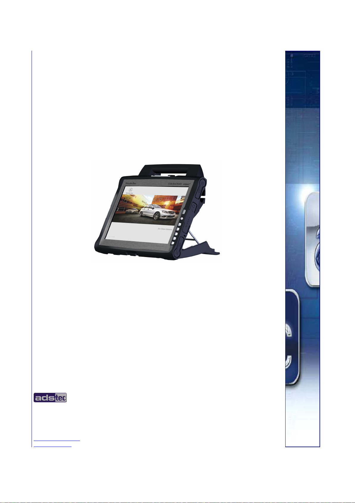
Compact4
Star Diagnosis
ads-tec GmbH
Raiffeisenstr.14
D-70771 Leinfelden-Echterdingen
Tel: +49 (0) 711 / 45894-0
Fax: +49 (0) 711 / 45894-990
mailbox@ads-tec.com
www.ads-tec.com

User Manual
User Manual Compact 4 V 1.2
User ManualUser Manual
Compact 4 V 1.2
Compact 4 V 1.2Compact 4 V 1.2
Copyright
ads-tec GmbH
Raiffeisenstr.14
D-70771 Leinfelden-Echterdingen
Germany
2222
© ads-tec GmbH • Raiffeisenstr.14 • 70771 Leinfelden-Echterdingen

User Manual
User Manual Compact 4 V 1.2
User ManualUser Manual
Compact 4 V 1.2
Compact 4 V 1.2Compact 4 V 1.2
INDEX
ABOUT US.......................................................................................................................................... 5
1 REMARKS ................................................................................................................................. 6
1.1 RELEVANT DATA COMMUNICATION WITH THE DEVICE............................................................................6
1.2 DESCRIPTION OF THE WARNING SYMBOLS USED IN THIS GUIDE ............................................................... 6
1.3 DATA, IMAGES, AMENDMENTS AND VARIATIONS .................................................................................6
1.4 TRADEMARKS............................................................................................................................. 6
1.5 COPYRIGHT ............................................................................................................................... 7
1.6 ENVIRONMENTAL CONDITIONS........................................................................................................7
1.7 CERTIFICATIONS / TESTINGS.......................................................................................................... 8
1.8 SCOPE OF DELIVERY ....................................................................................................................8
2 OPERATING INSTRUCTIONS ......................................................................................................... 9
2.1 OPERATING LOCATION .................................................................................................................9
2.2 DAMAGES DUE TO IMPROPER USE ...................................................................................................9
2.3 WARRANTY / REPAIRS................................................................................................................ 10
2.4 HANDLING AND PROPER DISPOSAL OF LITHIUM BATTERIES ................................................................... 10
2.5 SAFETY INSTRUCTIONS............................................................................................................... 10
3 INSTALLATION ........................................................................................................................ 11
3.1 MULTIFUNCTION UNIT................................................................................................................ 11
3.2 INTERFACES OF THE COMPACT
4
MULTIFUNCTION UNIT ........................................................................ 13
3.3 FUNCTIONS OF THE MULTIFUNCTION UNIT....................................................................................... 16
3.4 EXTERNAL DEVICE DIMENSIONS .................................................................................................... 17
3.5 EXTERNAL DEVICE DIMENSIONS INCLUDING DOCKING STATION.............................................................. 18
4 COMMISSIONING..................................................................................................................... 19
4.1 AVAILABLE INTERFACES .............................................................................................................. 19
4.2 READINESS FOR OPERATION CHECKS ............................................................................................. 19
5 FRONT PANEL FUNCTIONS.......................................................................................................... 20
5.1 STATUS INDICATORS.................................................................................................................. 20
5.2 FRONT CONTROL KEYS................................................................................................................ 21
5.3 TOUCH SCREEN ........................................................................................................................ 22
6 INTERFACES............................................................................................................................ 23
6.1 20V DC POWER SUPPLY ............................................................................................................. 23
6.2 14.4V DC ACCUMULATOR OPERATING MODE.................................................................................... 24
6.3 USB CONNECTIONS ................................................................................................................... 26
6.4 SD CONNECTOR ....................................................................................................................... 27
© ads-tec GmbH • Raiffeisenstr.14 • 70771 Leinfelden-Echterdingen
3333

User Manual
User Manual Compact 4 V 1.2
User ManualUser Manual
Compact 4 V 1.2
Compact 4 V 1.2Compact 4 V 1.2
6.5 NETWORK CONNECTION (RJ45) ................................................................................................... 28
6.6 EXPRESSCARD SLOT .................................................................................................................. 28
6.7 MIC IN .................................................................................................................................. 29
6.8 LINE OUT................................................................................................................................ 30
6.9 WLAN................................................................................................................................... 30
7 HARDWARE-SPECIFIC SOFTWARE................................................................................................ 31
7.1 SOFT KEYBOARD ....................................................................................................................... 37
8 ACCESSORIES.......................................................................................................................... 39
8.1 DVD DRIVE / EXTERNAL TYPE ...................................................................................................... 39
8.2 SAFETY OF LASER PRODUCTS....................................................................................................... 40
9 REGULATORY APPROVALS ......................................................................................................... 41
9.1 CERTIFICATIONS / TESTINGS........................................................................................................ 41
9.2 ELECTROMAGNETIC COMPATIBILITY (EMC)...................................................................................... 42
9.3 FCC-APPROVAL........................................................................................................................ 43
10 TECHNICAL DETAILS ................................................................................................................. 44
10.1 DISPLAY DATA.......................................................................................................................... 44
10.2 COMPUTER DATA ...................................................................................................................... 44
10.3 GENERAL DATA......................................................................................................................... 44
11 SERVICE AND SUPPORT............................................................................................................. 45
11.1 ADS-TEC SUPPORT .................................................................................................................... 45
11.2 COMPANY ADDRESS................................................................................................................... 45
4444
© ads-tec GmbH • Raiffeisenstr.14 • 70771 Leinfelden-Echterdingen
AAAABOUT US
BOUT US
BOUT USBOUT US
User Manual
User Manual Compact 4 V 1.2
User ManualUser Manual
Compact 4 V 1.2
Compact 4 V 1.2Compact 4 V 1.2
ads-tec GmbH
Raiffeisenstr. 14
70771 Leinfelden-Echterdingen
Tel: +49 (0) 711 / 45894-0
Fax: +49 (0) 711 / 45894-990
www.ads-tec.com
Germany
ads-tec GmbH provides large enterprises and globally active corporations with cutting edge
technology, up-to-date know-how and comprehensive services in the area of automation
technology, data processing technology and systems engineering.
ads-tec GmbH implements full automation solutions from planning to commissioning and is
specialized in handling and material handling technologies.
The data systems division develops and produces PC based solutions and offers a broad
range of industrial PCs, thin clients and embedded systems.
ads-tec is specialized in modifying and optimizing embedded operating systems and
develops software tools to complement its hardware platforms.
© ads-tec GmbH • Raiffeisenstr.14 • 70771 Leinfelden-Echterdingen
5555
User Manual
User Manual Compact 4 V 1.2
User ManualUser Manual
1
1 R
REMARKS
11
EMARKS
RR
EMARKSEMARKS
Compact 4 V 1.2
Compact 4 V 1.2Compact 4 V 1.2
1.1 RELEVANT DATA COMMUNICATION WITH THE DEVICE
The following documents are essential for setting up and operating this device:
USER MANUAL:
Contains information for installation, commissioning and operating the device along with
a
technical data of the device hardware.
1.2 DESCRIPTION OF THE WARNING SYMBOLS USED IN THIS GUIDE
Warning:
The “Warning” symbol precedes warnings on uses or operations that might either lead to
personal injury and/or hazards, or to any hardware and software damages.
Note:
This Symbol indicates special notes, terms and/or conditions that strictly need to be
observed to ensure optimised and/or zero-defect operations. It also precedes tips and
suggestions for efficient unit implementation and software optimisation.
1.3 DATA, IMAGES, AMENDMENTS AND VARIATIONS
The texts, data and images herein are not binding. The right to any subsequent amendment
and/or variation due to any technical and engineering progresses in the art whatsoever is
hereby reserved.
1.4 TRADEMARKS
It is hereby notified that any software and/or hardware trademarks further to any company
brand names as mentioned in this User’s Guide are all strictly subject to the various
trademark, brand name and patent protection rights.
WINDOWS®, WINDOWS® CE and WINDOWS® CE.net™ are registered trademarks of
Citrix® and ICA® are registered trademarks of Citrix Systems Inc.
Intel® and Pentium® are registered trademarks of Intel Corp.
IBM®, PS/2® and VGA® are registered trademarks of IBM Corp.
Microsoft Corp.
CompactFlash™ and CF™ are registered trademarks of SanDisk Corp.
Any further additional trademarks and/or brand names herein, be they domestic or
6666
international, are hereby duly acknowledged.
© ads-tec GmbH • Raiffeisenstr.14 • 70771 Leinfelden-Echterdingen

1.5 COPYRIGHT
This User’s Guide inclusive of all the images it contains is entirely proprietary and subject to
copyright. Any irregular use of this Guide by third parties infringing copyright terms is thus
strictly forbidden. Reproduction, translation, as well as electronic and photographic image
storage and/or amendment processes, are subject to prior written authorisation directly by
M/s. ads-tec GmbH.
Any violation and infringement thereto will be held liable for compensation of all damages.
1.6 ENVIRONMENTAL CONDITIONS
The device may be operated under the following conditions. Failure to observe these
specifications will terminate any warranty for this device. Ads-tec cannot be held liable for
any damages arising due to improper use and handling.
• Temperature with fan
In operation 0 … 40 C
For storage -20 … 60 C
User Manual
User Manual Compact 4 V 1.2
User ManualUser Manual
Compact 4 V 1.2
Compact 4 V 1.2Compact 4 V 1.2
(Because of the integrated maximum temperature memory)
• Humidity
In operation 10 … 85% without any condensate
For storage 10 … 85% without any condensate
• Vibrations
In operation MIL-STD-810F acc to method 514.5, figure C1
• Shock resistance
In operation 15 G, with a half-wave of 11 ms duration
(DIN EN 60068-2-27)
© ads-tec GmbH • Raiffeisenstr.14 • 70771 Leinfelden-Echterdingen
7777
User Manual
User Manual Compact 4 V 1.2
User ManualUser Manual
Compact 4 V 1.2
Compact 4 V 1.2Compact 4 V 1.2
1.7 CERTIFICATIONS / TESTINGS
The Compact 4 system has the following certifications:
UL/cUL201
FCC permission
GOST-R certificate
MIC certification
Application for WLAN certificates
for 802.11 a/b/g
Note:
EN61000-6-2 device complies with standard CE compatibility (class A)
EN61000-6-4 device complies with standard
Application for certification is filed
Application for certification is filed
Application for certification will be filed
Application for certification will be filed
EU countries
2.400 MHz – 2.483,5 MHz
5.150 MHz – 5.350 MHz
5.470 MHz – 5.725 MHz
Application for certification in USA / Canada
2.400 MHz - 2483,5 MHz
5.150 MHz - 5.350 MHz
5.725 MHz – 5.875 MHz
Application for certification in Japan
2.400 MHz – 2.483,5 MHz
5.150 MHz – 5.350 MHz
5.470 MHz – 5.725 MHz
Application for certification in Australia
2.400 MHz – 2.483,5 MHz
5.150 MHz – 5.350 MHz
5.470 MHz – 5.725 MHz
A respective conformity declaration for the authority in charge is available on request from
the manufacturer.
All connected components, as well as cable connections must also meet these
requirements for compliance with the EMC legislation. For this reason, screened bus and
LAN cables including screened connectors must be used and installed according to the
instructions in this user manual.
1.8 SCOPE OF DELIVERY
The following components are included in the scope of delivery:
• 1 x device
• 1 x transport case
• 1 x 20V DC power supply unit
• 1 x multiplex adapter
• 1 x multifunctional unit
• 1 x DVD drive, external
8888
© ads-tec GmbH • Raiffeisenstr.14 • 70771 Leinfelden-Echterdingen
2
2 O
OPERATING INSTRUCTION
22
PERATING INSTRUCTIONSSSS
OO
PERATING INSTRUCTIONPERATING INSTRUCTION
This device contains electrical voltages and extremely sensitive components. The
manufacturer, or a service partner authorised by the manufacturer, should be consulted if
you plan to make any modifications. For this type of work, the device must be switched off
at the mains and the power lead must be disconnected. Suitable measures for avoiding
electrostatic discharge towards parts of the components when touching the equipment must
be taken. If the device is opened by an unauthorised person, hazards for the user might
arise and any warranty claim will cease.
General instructions:
• All users must read this manual and have access to it at all times.
• Installation, commissioning and operation may only be carried out by trained and
qualified staff.
• The security instructions and the manual itself must be observed by all persons who
work with this device.
• At the location of use the valid guidelines and regulations for accident prevention
must be observed.
• The manual contains the most important instructions on how to use this device in a
safe way.
• Appropriate storage, proper transport, installation and commissioning, as well as
careful operation are prerequisites for ensuring safe and proper operation of the
device.
Warning:
User Manual
User Manual Compact 4 V 1.2
User ManualUser Manual
Compact 4 V 1.2
Compact 4 V 1.2Compact 4 V 1.2
Any leads (e.g. power leads, interface cables) may only be connected if the device is
switched off in order to avoid damaging the device.
2.1 OPERATING LOCATION
This device is designed for use in industry, in particular in workshops. You have to take care
that the environmental conditions indicated in the technical data specification are met. Using
the device in non-specified environments, for example, on board ships, or in areas that
might contain explosive gases or in extreme heights is prohibited.
Warning:
The device may only be switched on after acclimatising to the ambient temperature in
order to avoid condensate accumulation. The same applies if the device has previously
been exposed to extreme temperature variations.
To avoid overheating: The device must not be exposed to direct radiation by sunlight or
any other light or heat source.
2.2 DAMAGES DUE TO IMPROPER USE
Should the service system have evident signs of damages incurred e.g. due to wrong
operation or storage conditions or due to improper unit use, the unit must be
decommissioned or scrapped. Ensure that it is safe from accidental re-implementation.
© ads-tec GmbH • Raiffeisenstr.14 • 70771 Leinfelden-Echterdingen
9999
User Manual
User Manual Compact 4 V 1.2
User ManualUser Manual
Compact 4 V 1.2
Compact 4 V 1.2Compact 4 V 1.2
2.3 WARRANTY / REPAIRS
During the unit warranty period, any repairs thereto must strictly be conducted solely by the
manufacturer or by service personnel that has been duly authorised by the manufacturer.
2.4 HANDLING AND PROPER DISPOSAL OF LITHIUM BATTERIES
Caution:
Danger of explosion and the release of toxic substances
Lithium batteries should not be exposed to fire, soldered, recharged, opened, shortcircuited, reversed or heated above 100 °C and they should be disposed of properly as well
as protected against sunlight, moisture and condensation.
The lithium battery can only be replaced by the same type or a type recommended by the
manufacturer.
The used lithium battery should be disposed of in accordance with local legal regulations.
2.5 SAFETY INSTRUCTIONS
Warning:
All unit assembly operations must be strictly conducted only under safe, secure and zeropotential conditions.
Special Note:
When handling parts and components susceptible to electrical discharge, please
accurately observe all the relevant safety provisions.
(DIN EN 61340-5-1 / DIN EN 61340-5-2 refers)
10
10
1010
© ads-tec GmbH • Raiffeisenstr.14 • 70771 Leinfelden-Echterdingen
3
3 I
INSTALLATION
NSTALLATION
33
II
NSTALLATIONNSTALLATION
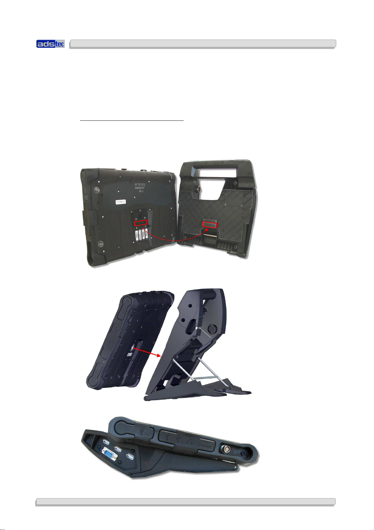
3.1 MULTIFUNCTION UNIT
The device may be connected to a multifunction unit on the back by using a docking
interface.
INSTALLING THE MULTIFUNCTION UNIT
Pay attention when attaching the device on top of the multifunction unit, that the docking
plug, and the docking socket located at the Compact4 device, are safely connected with
each other. Make sure that the Compact4 device is properly attached to the multifunction
unit. (Figure 3)
User Manual
User Manual Compact 4 V 1.2
User ManualUser Manual
Compact 4 V 1.2
Compact 4 V 1.2Compact 4 V 1.2
© ads-tec GmbH • Raiffeisenstr.14 • 70771 Leinfelden-Echterdingen
11
11
1111

User Manual
User Manual Compact 4 V 1.2
User ManualUser Manual
Compact 4 V 1.2
Compact 4 V 1.2Compact 4 V 1.2
Warning:
If this device is to be used in connection with a multifunction unit, the supplied screws
must be used in order to tightly connect the device to it.
The supplied type of screws is 4 x DIN 7984 M5 x 5, black.
12
12
1212
© ads-tec GmbH • Raiffeisenstr.14 • 70771 Leinfelden-Echterdingen
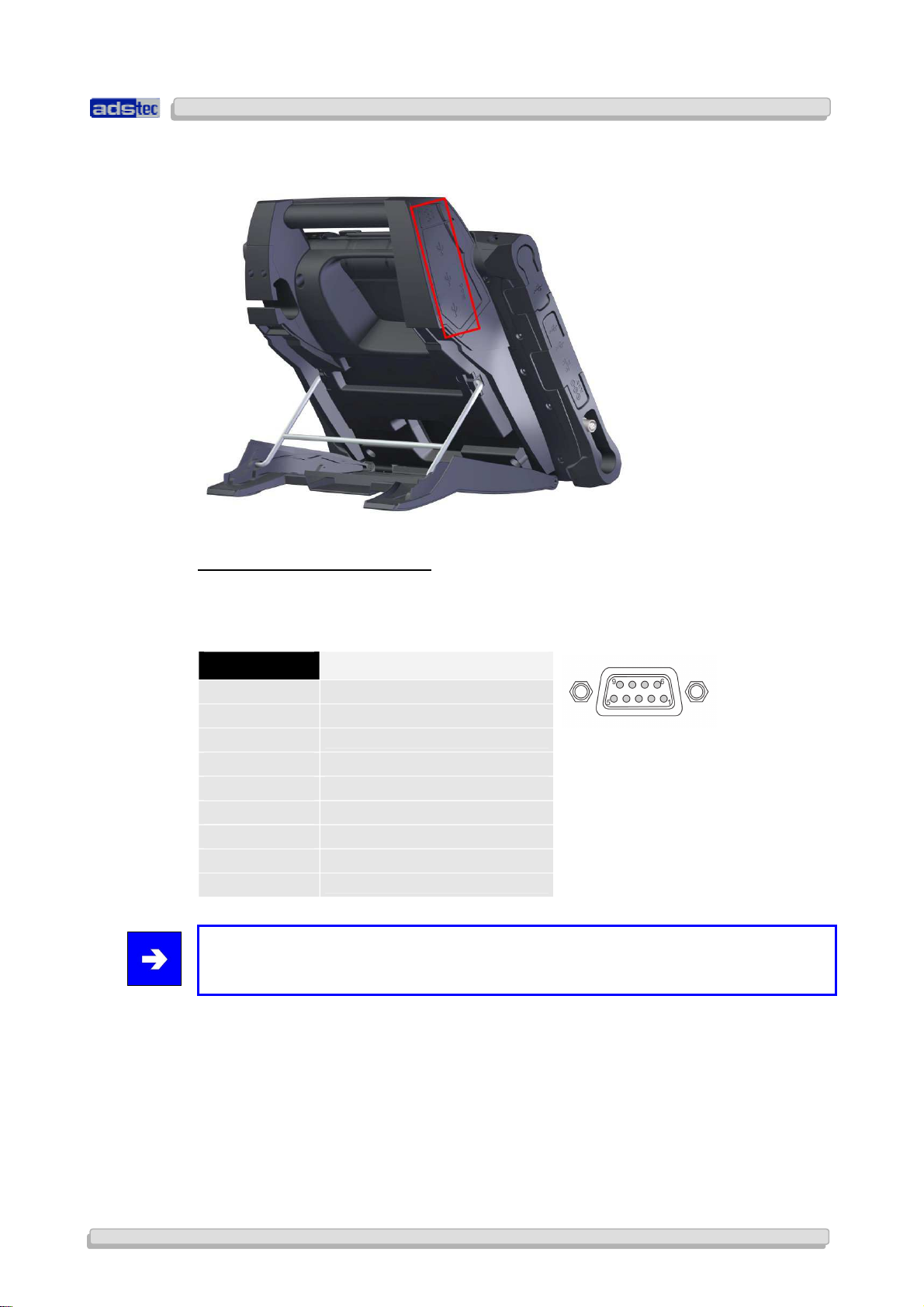
3.2 INTERFACES OF THE COMPACT
4
MULTIFUNCTION UNIT
User Manual
User Manual Compact 4 V 1.2
User ManualUser Manual
Compact 4 V 1.2
Compact 4 V 1.2Compact 4 V 1.2
COM SERIAL INTERFACE (RS 232)
The serial interface is also used for digital and analogue data transmission. The RS 232
interface can be connected by using a commercially available 9-pin SUB-D cable.
PIN NUMBER SIGNAL NAME
1
2
3
4
5
6
7
8
9
DCD
RxD
TxD
DTR
GND
DSR
RTS
CTS
RI
Note:
This interface is not electrically isolated.
© ads-tec GmbH • Raiffeisenstr.14 • 70771 Leinfelden-Echterdingen
13
13
1313
User Manual
User Manual Compact 4 V 1.2
User ManualUser Manual
Compact 4 V 1.2
Compact 4 V 1.2Compact 4 V 1.2
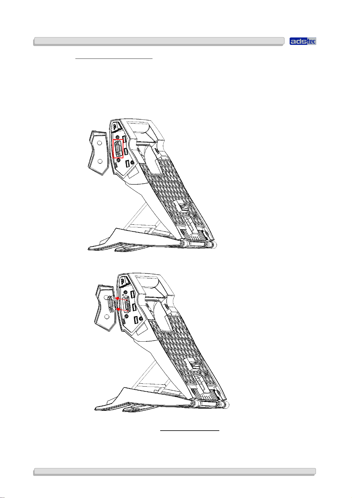
CHANGING THE COM ADAPTER
The COM interface is equipped with an attached adapter (gender changer) in order to avoid
damage to the COM interface. You can replace this adapter, should it be damaged. Please
proceed as follows in order to replace the adapter:
1) Open the rubber cover of the Compact4 multifunction unit and subsequently loosen both
SUB-D bolts by using a suitable screw driver or socket wrench...
2) Once both SUB-D bolts are removed, the adapter (gender changer) can be pulled off.
3) Attach the new adapter to the COM interface. Tighten both
SUB-D bolts with a torque of NCM TO BE DEFINED and close the rubber cover.
14
14
1414
© ads-tec GmbH • Raiffeisenstr.14 • 70771 Leinfelden-Echterdingen
 Loading...