

ADS-TEC TT13 User Manual
Version 1.8
User Manual
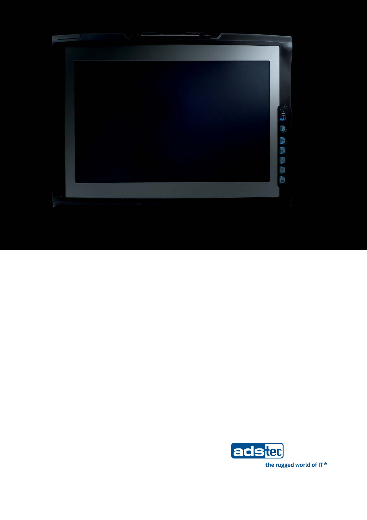
Tablet PCs
TT13
Product Portfolio
Tablet PCs TT13
2
Copyright
© ads-tec GmbH
Raiffeisenstr.14
D-70771 Leinfelden-Echterdingen
Germany
© ads-tec GmbH • Raiffeisenstr.14 • 70771 Leinfelden-Echterdingen

Tablet PCs TT13
INDEX
ABOUT US .......................................................................................................................................... 5
REMARKS .............................................................................................................................. ... 6
1
RELEVANT DATA COMMUNICATION WITH THE DEVICE ......................................................................... 6
1.1
DESCRIPTION OF THE WARNING SYMBOLS USED IN THIS GUIDE ............................................................. 6
1.2
DATA, IMAGES, AMENDMENTS AND VARIATIONS ............................................................................... 6
1.3
TRADEMARKS ......................................................................................................................... 6
1.4
COPYRIGHT ........................................................................................................................... 7
1.5
CERTIFICATIONS / TESTS ........................................................................................................... 7
1.6
SCOPE OF DELIVERY ................................................................................................................. 8
1.7
OPERATING INSTRUCTIONS ......................................................................................................... 9
2
OPERATING LOCATION .............................................................................................................. 9
2.1
DAMAGES DUE TO IMPROPER USE ................................................................................................ 9
2.2
WARRANTY / REPAIRS ............................................................................................................ 10
2.3
HANDLING AND PROPER DISPOSAL OF LITHIUM BATTERIES ................................................................. 10
2.4
SAFETY INSTRUCTIONS ........................................................................................................... 10
2.5
EXTERNAL DEVICE DIMENSIONS ................................................................................................. 11
2.6
COMMISSIONING ..................................................................................................................... 12
3
AVAILABLE INTERFACES ........................................................................................................... 12
3.1
READINESS FOR OPERATION CHECKS .......................................................................................... 13
3.2
TOUCHSCREEN ..................................................................................................................... 13
3.3
FRONT PANEL FUNCTIONS .......................................................................................................... 14
4
STATUS INDICATORS .............................................................................................................. 14
4.1
FRONT CONTROL KEYS ............................................................................................................ 16
4.2
INTERFACES ............................................................................................................................ 18
5
20V DC POWER SUPPLY .......................................................................................................... 18
5.1
14.4V DC BATTERY OPERATING MODE ........................................................................................ 18
5.2
USB CONNECTIONS ............................................................................................................... 20
5.3
ODU-INTERFACE (OPTIONAL) ................................................................................................... 21
5.4
NETWORK CONNECTION (RJ45) ................................................................................................ 23
5.5
MIC IN .............................................................................................................................. 24
5.6
LINE OUT ............................................................................................................................ 25
5.7
EXPRESSCARD SLOT ............................................................................................................... 25
5.8
SOFTWARE & DRIVER INSTALLATION ........................................................................................... 26
6
BATTERY INFORMATION & DIAGNOSTICS TOOL ............................................................................... 26
6.1
TT13 HDD PROTECTION ........................................................................................................ 29
6.2
TT13 WIRELESS KONFIGURATION ............................................................................................. 31
6.3
TT13 TOUCH ROTATION ......................................................................................................... 34
6.4
TT13 MONITORING ............................................................................................................... 37
6.5
TT13 ADSXTERN TEST ............................................................................................................ 38
6.6
MANUAL REINSTALLATION ....................................................................................................... 38
6.7
INSTALLATION OF THE TT13 SOFTWARE PACKAGE ......................................................................... 39
6.8
© ads-tec GmbH • Raiffeisenstr.14 • 70771 Leinfelden-Echterdingen
3

6.9 WLAN ................................................................................................................................ 44
BLUETOOTH ......................................................................................................................... 47
6.10
UMTS (OPTIONAL) ................................................................................................................ 48
6.11
RFID READER (OPTIONAL) ....................................................................................................... 57
6.12
CAMERA (OPTIONAL) ............................................................................................................... 60
6.13
SOFT KEYBOARD .................................................................................................................... 64
6.14
ACCESSORIES ......................................................................................................................... 66
7
DVD DRIVE / EXTERNAL TYPE (OPTIONAL ...................................................................................... 66
7.1
7.2
LASER PRODUCT SAFETY ........................................................................................................... 67
TRANSPORT CASE .................................................................................................................. 68
7.3
BATTERY CHARGING STATION C4/TT13 ...................................................................................... 69
7.4
SUBSTITUTION POWER SUPPLY .................................................................................................. 73
7.5
7.6
CAR POWER SUPPLY ............................................................................................................... 73
SUBSTITUTION-BATTERY .......................................................................................................... 73
7.7
TT13 MECHANICAL DOCKING ADAPTER ....................................................................................... 74
7.8
TABLE STAND ....................................................................................................................... 76
7.9
WALL BRACKET ..................................................................................................................... 77
7.10
SUBSTITUTION PACK OF TOUCH STYLUS ....................................................................................... 77
7.11
3 POINT CORD ...................................................................................................................... 78
7.12
HAND STRAP ........................................................................................................................ 81
7.13
ODU 10POL TO RS232 ADAPTERCABLE 1M .................................................................................. 83
7.14
PROTECTION BEZEL ................................................................................................................ 83
7.15
Tablet PCs TT13
CERTIFICATIONS ..................................................................................................................... 84
8
CERTIFICATIONS / TESTS ......................................................................................................... 84
8.1
ELECTROMAGNETIC COMPATIBILITY (EMC) ................................................................................... 85
8.2
FCC APPROVAL ..................................................................................................................... 86
8.3
TECHNICAL DETAILS ................................................................................................................. 87
9
DISPLAY DATA ....................................................................................................................... 87
9.1
COMPUTER DATA ................................................................................................................... 87
9.2
GENERAL DATA ...................................................................................................................... 87
9.3
SERVICE AND SUPPORT ............................................................................................................ 88
10
ADS-TEC SUPPORT.................................................................................................................. 88
10.1
10.2
COMPANY ADDRESS ................................................................................................................ 88
4
© ads-tec GmbH • Raiffeisenstr.14 • 70771 Leinfelden-Echterdingen
Tablet PCs TT13
A
ads-tec GmbH
Raiffeisenstr. 14
D-70771 Leinfelden-Echterdingen
Tel: +49 711 45894-0
Fax: +49 711 45894-990
www.ads-tec.com
ads-tec GmbH provides large enterprises and globally active corporations with cutting edge
technology, up-to-date know-how and comprehensive services in the area of automation
technology, data processing technology and systems engineering.
BOUT US
ads-tec GmbH implements full automation solutions from planning to commissioning and is
specialized in handling and material handling technologies.
The data systems division develops and produces PC based solutions and offers a broad
range of industrial PCs, thin clients and embedded systems.
ads-tec is specialized in modifying and optimizing embedded operating systems and
develops software tools to complement its hardware platforms.
© ads-tec GmbH • Raiffeisenstr.14 • 70771 Leinfelden-Echterdingen
5
1 REMARKS
1.1 RELEVANT DATA COMMUNICATION WITH THE DEVICE
The following documents are essential for setting up and operating this device:
SER MANUAL:
U
Contains information for installation, commissioning and operating the device along with
a
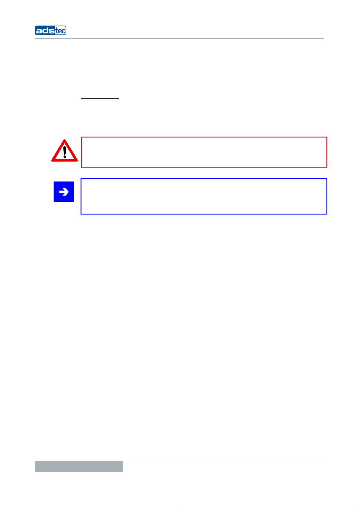
1.2 DESCRIPTION OF THE WARNING SYMBOLS USED IN THIS GUIDE
technical data of the device hardware.
Warning:
The “Warning” symbol precedes warnings on uses or operations that might either lead to
personal injury and/or hazards, or to any hardware and software damages.
Note:
This Symbol indicates special notes, terms and/or conditions that strictly need to be
observed to ensure optimised and/or zero-defect operations. It also precedes tips and
suggestions for efficient unit implementation and software optimisation.
Tablet PCs TT13
1.3 DATA, IMAGES, AMENDMENTS AND VARIATIONS
The texts, data and images herein are not binding. The right to any subsequent
amendment and/or variation due to any technical and engineering progresses in the art
whatsoever is hereby reserved.
1.4 TRADEMARKS
It is hereby notified that any software and/or hardware trademarks further to any
company brand names as mentioned in this User’s Guide are all strictly subject to the
various trademark, brand name and patent protection rights.
®
Windows
®
, Pentium®, Atom™ , Core™2 are registered trademarks of Intel Corp.
Intel
CompactFlash™ and CF™ are registered trademarks of SanDisk Corp.
®
RITTAL
is a registered trademark of the Rittal Werk Rudolf Loh GmbH & Co. KG.
Any further additional trademarks and/or brand names herein, be they domestic or
international, are hereby duly acknowledged.
, Windows® CE are registered trademarks of Microsoft Corp.
®
IBM
, PS/2® and VGA® are registered trademarks of IBM Corp.
6
© ads-tec GmbH • Raiffeisenstr.14 • 70771 Leinfelden-Echterdingen
Tablet PCs TT13
1.5 COPYRIGHT
This User’s Guide inclusive of all the images it contains is entirely proprietary and subject
to copyright. Any irregular use of this Guide by third parties infringing copyright terms is
thus strictly forbidden. Reproduction, translation, as well as electronic and photographic
image storage and/or amendment processes, are subject to prior written authorisation
directly by M/s. ads-tec GmbH.
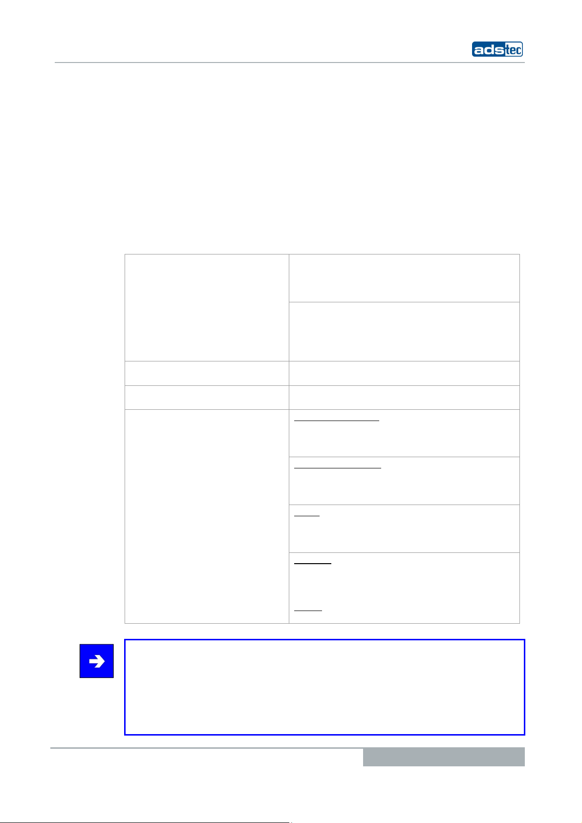
1.6 CERTIFICATIONS / TESTS
Any violation and infringement thereto will be held liable for compensation of all damages.
The TT13 system has the following certifications:
CE compatibility EN 61000-6-3:2007 Electromagnetive Emission,
UL/cUL201
GOST-R certificate
WLAN certificates for 802.11 a/b/g
for the
Note:
A respective conformity declaration for the authority in charge is available at the
manufacturer and may be viewed on request.
All connected components, as well as cable connections must also meet these
requirements for compliance with the EMC legislation. For this reason, screened bus and
LAN cables including screened connectors must be used and installed according to the
instructions in this user manual.
Klasse B
EN 55022:2006 Electromagnetive Emission
EN 61000-6-2:2005 Electromagnetive Emission
EN55024:1998+A1:2001+A2:2003
Electromagnetive Emission
USL/CNL E217133
Device complies with standard
EU countries (ETSI)
2,400 MHz – 2,483.5 MHz
5,150 MHz – 5,350 MHz
5,470 MHz – 5,725 MHz
USA / Canada (FCC)
2,400 MHz - 2,483.5 MHz
5,150 MHz - 5,350 MHz
5.725 MHz – 5.850 MHz
Japan
2,400 MHz – 2,483.5 MHz
5,150 MHz – 5,350 MHz
5,470 MHz – 5,725 MHz
Australia
2,400 MHz – 2,483.5 MHz
5,150 MHz – 5,350 MHz
5,470 MHz – 5,725 MHz
Russia
2,400 MHz – 2,483.5 MHz
© ads-tec GmbH • Raiffeisenstr.14 • 70771 Leinfelden-Echterdingen
7

1.7 SCOPE OF DELIVERY
The following components are included in the scope of delivery:
• 1 x device
• 1 x 20V DC power supply unit
• 2 x batteries
S AN OPTION:
A
• 1 x DVD drive, external
• 1 x transport case
Tablet PCs TT13
8
© ads-tec GmbH • Raiffeisenstr.14 • 70771 Leinfelden-Echterdingen
Tablet PCs TT13
2 OPERATING INSTRUCTIONS
This device contains electrical voltages and extremely sensitive components. The
manufacturer, or a service partner authorised by the manufacturer, should be consulted if
you plan to make any modifications. For this type of work, the device must be switched off
at the mains and the power lead must be disconnected. Suitable measures for avoiding
electrostatic discharge towards parts of the components when touching the equipment
must be taken. If the device is opened by an unauthorised person, hazards for the user
might arise and any warranty claim will cease.
General instructions:
• All users must read this manual and have access to it at all times.
• Installation, commissioning and operation may only be carried out by trained and
qualified staff.
• The security instructions and the manual itself must be observed by all persons
who work with this device.
• At the location of use the valid guidelines and regulations for accident prevention
must be observed.
• The manual contains the most important instructions on how to use this device in
a safe way.
• Appropriate storage, proper transport, installation and commissioning, as well as
careful operation are prerequisites for ensuring safe and proper operation of the
device.
Warning:
Any leads (e.g. power leads, interface cables) may only be connected if the device is
switched off in order to avoid damaging the device.
2.1 OPERATING LOCATION
This device is designed for professional and portable use indoors and outdoors. You have
to take care that the environmental conditions specified in the technical data specification
are met.
Warning:
The device may only be switched on after acclimatising to the ambient temperature in
order to avoid condensate accumulation. The same applies if the device has previously
been exposed to extreme temperature variations.
To avoid overheating in operation: The device must not be exposed to direct radiation by
sunlight or any other light or heat source.
2.2 DAMAGES DUE TO IMPROPER USE
Should the service system have evident signs of damages incurred e.g. due to wrong
operation or storage conditions or due to improper unit use, the unit must be
decommissioned or scrapped. Ensure that it is safe from accidental re-implementation.
© ads-tec GmbH • Raiffeisenstr.14 • 70771 Leinfelden-Echterdingen
9
2.3 WARRANTY / REPAIRS
During the unit warranty period, any repairs thereto must strictly be conducted solely by
the manufacturer or by service personnel that has been duly authorised by the
manufacturer.
2.4 HANDLING AND PROPER DISPOSAL OF LITHIUM BATTERIES
This device contains a lithium battery to supply the systemclock until there is no power
supply connected. Depending on exposure, the battery has a lifetime of 3-5 years.
Note:
High thermal exposure will age the battery faster.
Warning:
By using the wrong types of batteries, there is acute danger of explosion.
Warning:
Lithium batteries should not be exposed to fire, soldered, recharged, opened, shortcircuited, reversed or heated above 100 °C and they should be disposed of properly as
well as protected against sunlight, moisture and condensation.
Tablet PCs TT13
The lithium battery can only be replaced by the same type or a type recommended by the
manufacturer.
The used lithium battery should be disposed of in accordance with local legal regulations.
2.5 SAFETY INSTRUCTIONS
Warning:
All unit assembly operations must be strictly conducted only under safe, secure and zeropotential conditions.
Special Note:
When handling parts and components susceptible to electrical discharge, please
accurately observe all the relevant safety provisions.
(DIN EN 61340-5-1 / DIN EN 61340-5-2 refers)
10
© ads-tec GmbH • Raiffeisenstr.14 • 70771 Leinfelden-Echterdingen
Tablet PCs TT13
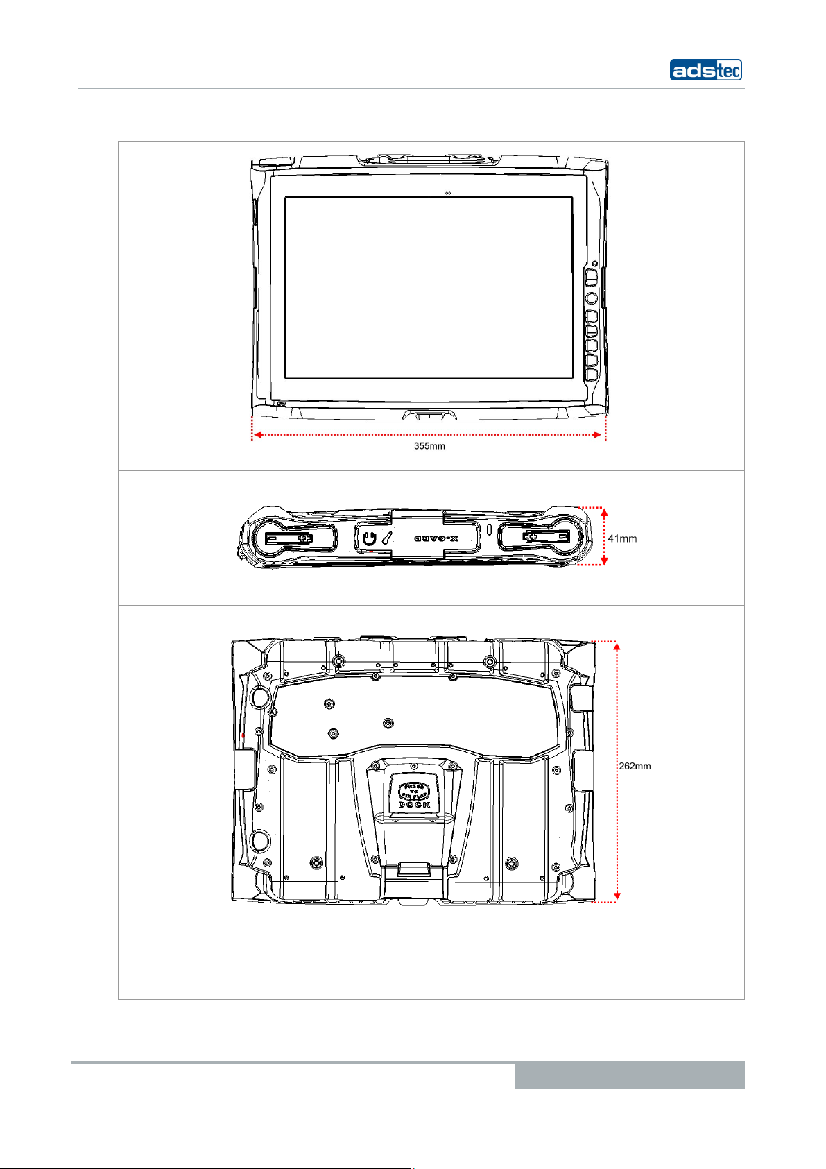
2.6 EXTERNAL DEVICE DIMENSIONS
© ads-tec GmbH • Raiffeisenstr.14 • 70771 Leinfelden-Echterdingen
11
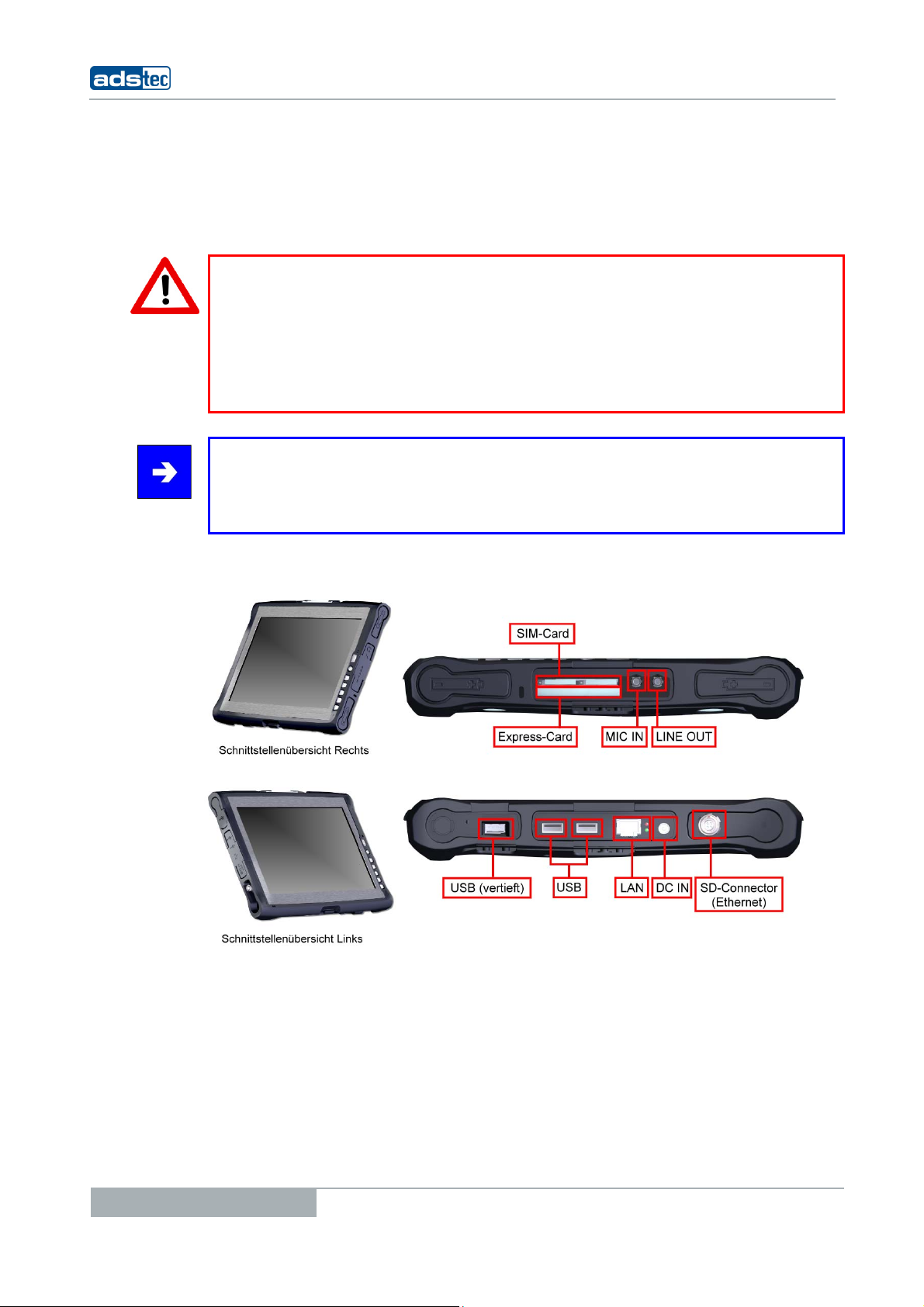
3 COMMISSIONING
The power supply connection and interfaces of this device are installed at the side of case.
All supply leads and all required data leads have to be connected before starting
commissioning.
Warning:
The device must be switched off before connecting or disconnecting any cables in order
to prevent damage to the electronics!
The device may only be switched on after acclimatising to the ambient temperature in
order to avoid condensate accumulation. Make sure to meet the permissible voltage
requirements for this device.
After switching off and before switching on you must wait for at least 10 seconds.
Note:
The screen of a data cable must always be connected with the connector housing (EMC).
Under the embedded operating system, interfaces must explicitly be enabled and required
drivers must be installed in order to be able to use them.
Tablet PCs TT13
3.1 AVAILABLE INTERFACES
12
© ads-tec GmbH • Raiffeisenstr.14 • 70771 Leinfelden-Echterdingen
Tablet PCs TT13
3.2 READINESS FOR OPERATION CHECKS
Accurately check the unit for any hidden damages possibly incurred during improper
transport and/or handling or wrong operation site and/or storage conditions (e.g. smoke
emissions or formation by the unit, etc.). If any damages are found, the unit must be
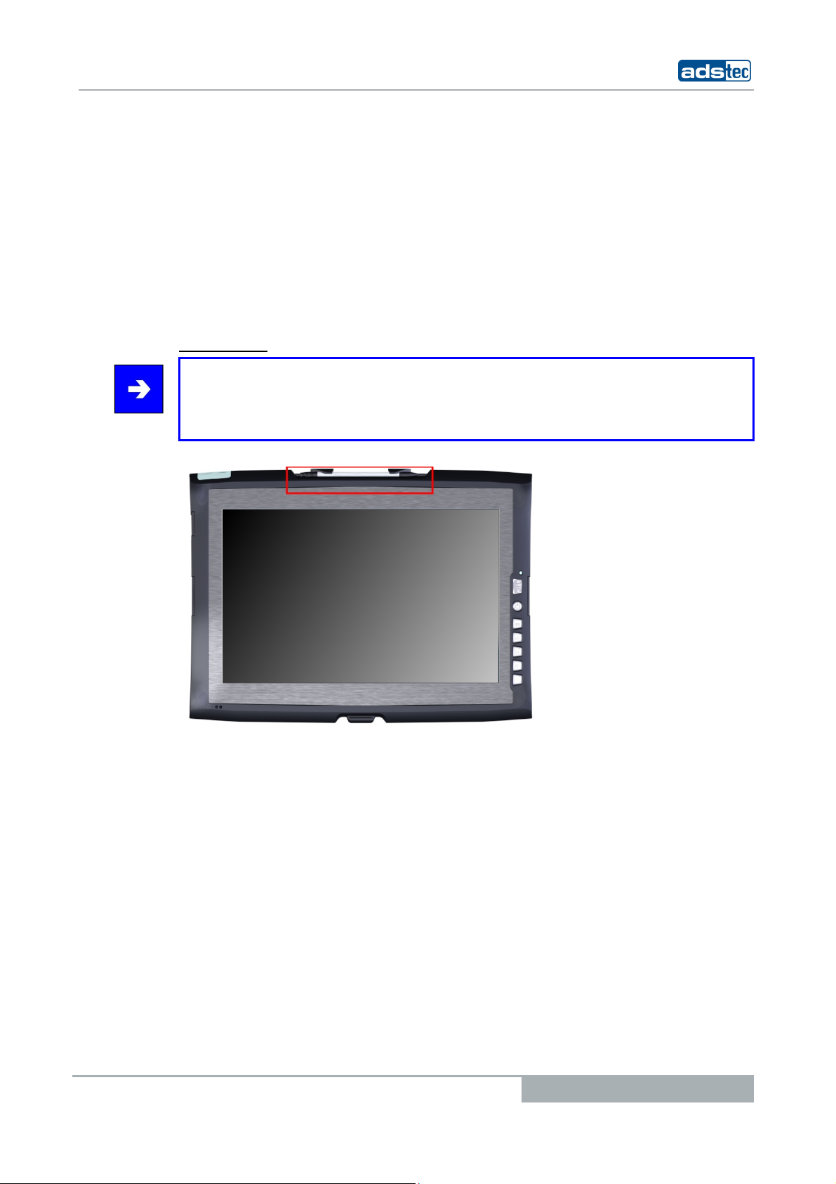
3.3 TOUCHSCREEN
decommissioned or scrapped. Ensure that it is safe from accidental re-implementation.
The control system is equipped with an analogue, resistive touchscreen. The driver
software required for its use is already integrated in the respective operating system.
OUCH STYLUS
T
Note:
This device is equipped with a supplied touch stylus for comfortably operating the
touchscreen. This stylus should be used for all works on the device in order to avoid
damage to the display.
© ads-tec GmbH • Raiffeisenstr.14 • 70771 Leinfelden-Echterdingen
13
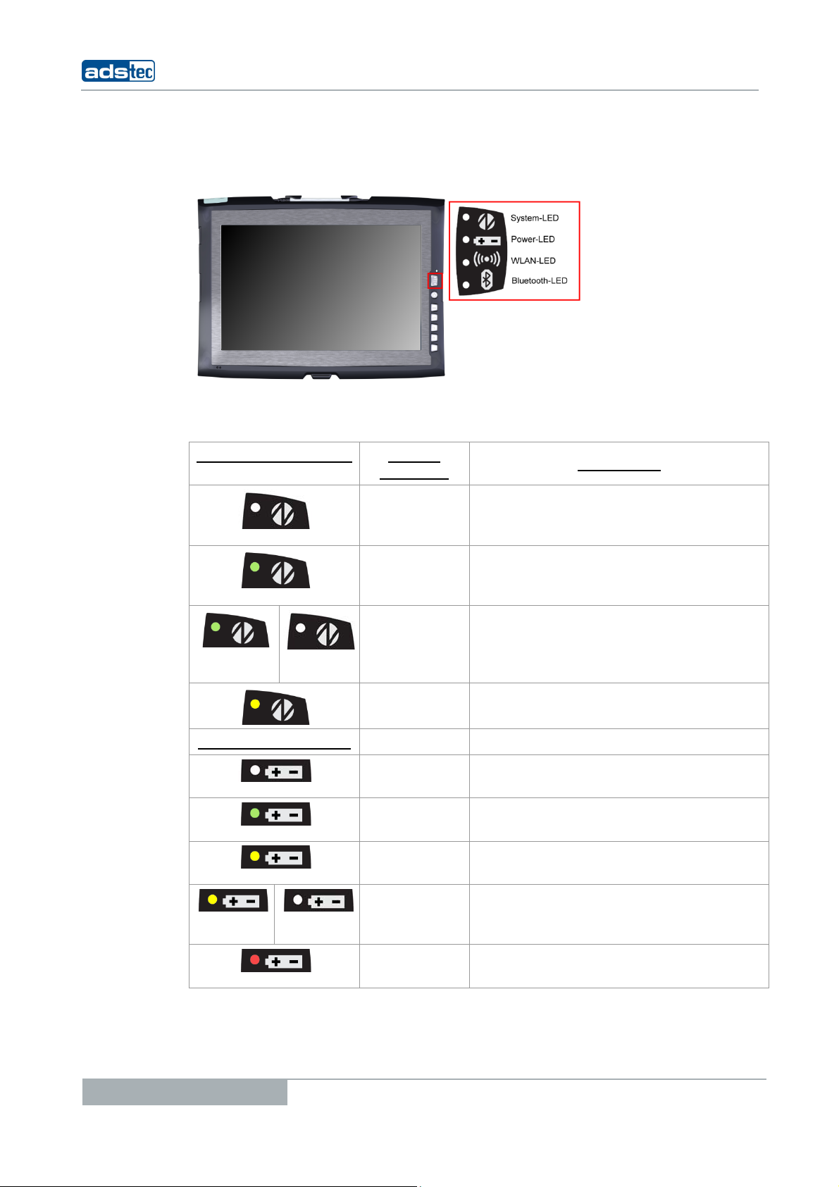
4 FRONT PANEL FUNCTIONS
4.1 STATUS INDICATORS
This device is equipped with different status LEDs in the front. These LEDs indicate current
events, like the system activity state, the current accumulator charge status and WLAN
activities.
SYSTEM LED INDICATORS DISPLAY
BEHAVIOUR
ESCRIPTION
D
Tablet PCs TT13
- The device is not connected to any
power supply (power
adapter/accumulator)
Static The device is connected to a power
supply (power adapter/accumulator)
and switched on
Flashes The device is in suspend mode (this
mode can be set up using the
operating system, re-activation via
power button)
Static
Device is accessing the HDD
POWER LED INDICATORS
- Device is not connected to any power
supply
Static Device is supplied by the charged
accumulator
Static Device is supplied from an external
power supply
Flashes Internal accumulators of the device are
charged (device must be connected to
a power supply (power adapter)
Static Device works with the accumulators'
14
© ads-tec GmbH • Raiffeisenstr.14 • 70771 Leinfelden-Echterdingen
residual capacity
Tablet PCs TT13
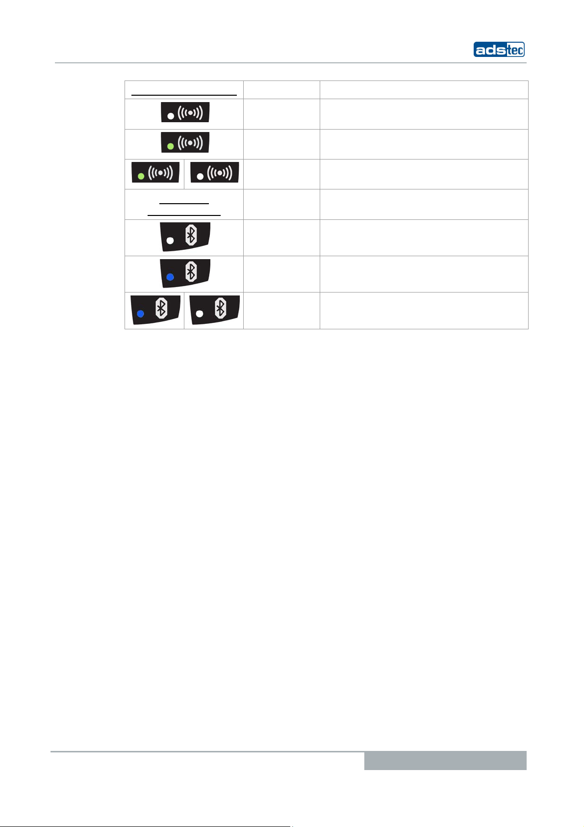
WLAN LED INDICATORS
Static Device is not connected with a WLAN
Static Device is connected with a WLAN
Flashes Device is connected with a WLAN
network
network
network and has data traffic
BLUETOOTH
INDICATORS
LED
Static
Bluetooth module is disabled.
Static
Bluetooth module is enabled.
Flashes
Device is connected with a Bluetooth
subscriber and has data traffic
© ads-tec GmbH • Raiffeisenstr.14 • 70771 Leinfelden-Echterdingen
15
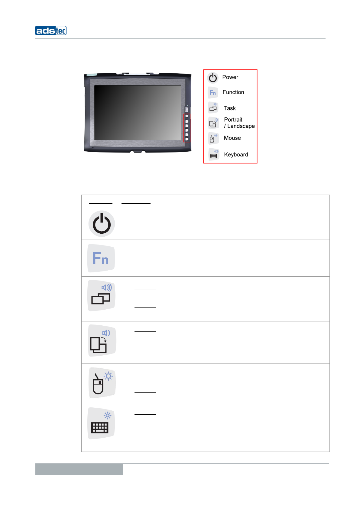
4.2 FRONT CONTROL KEYS
The keys on the front panel are occupied with the following functions by a specific driver in
the soft keyboard:
YMBOL: FUNCTION:
S
Tablet PCs TT13
ON / OFF pushbutton for the device (approx. 0,5 seconds delayed)
Shift key (SHIFT) for activating the second keyboard level. This key
must be pressed simultaneously with the desired function key
Level 1:
Change task (Alt+ESC) in Windows
Level 2:
Increase the system volume
Level 1:
Switch from Potrait view to Landscape view
Level 2:
Decrease the system volume
Level 1:
Right mouse-key function
Level 2:
Increase display brightness
16
Level 1:
Activate and deactivate the soft keyboard for letter/character input
using the touchscreen.
Level 2:
Decrease display brightness
© ads-tec GmbH • Raiffeisenstr.14 • 70771 Leinfelden-Echterdingen
Tablet PCs TT13
Warning:
The front control keys should not be operated with a touch stylus but with the fingers,
only.
Note:
All function keys in the front panel, except for the ON / OFF pushbutton and the Fn
button, have 2 function levels each. The primary function is activated by simply pushing
the respective key. The second function level (small symbol to the top right) can be
activated each time by pushing the Fn key first, and then additionally pushing the desired
function key. It is essential to keep the Fn key always pushed in order to activate the
second function level.
Note:
If the software keyboard is not installed, only the functions for display settings and
volume control are active. The controller display will not be output on the display, in this
case. Above described functions are pre-set ex works.
© ads-tec GmbH • Raiffeisenstr.14 • 70771 Leinfelden-Echterdingen
17
5 INTERFACES
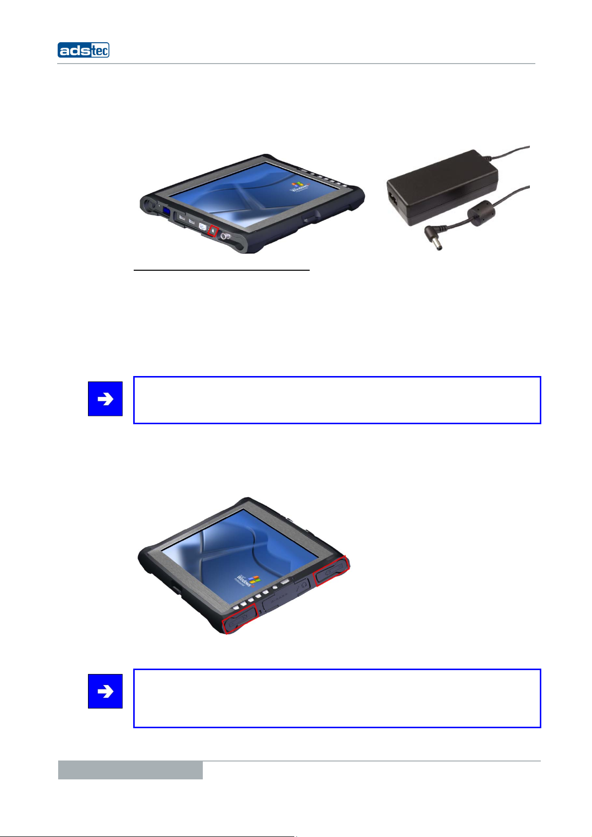
5.1 20V DC POWER SUPPLY
T
ECHNICAL DATA OF THE POWER ADAPTER
• Power consumption: Max. 70 Watts
• Input voltage: 100…240 V AC
• Mains frequency: 50…60Hz
• Current consumption: 3.5A (230V AC)
• Max. switch-on current: < 60A (230V AC)
Note:
The typical power consumption of this device is indicated in the "Technical details"
chapter.
Tablet PCs TT13
5.2 14.4V DC BATTERY OPERATING MODE
The device is equipped with two batteries slots, by means of which the device can be
supplied with power, alternatively. It is provided with a hot swap function which allows you
to replace the batteries without rebooting.
The batteries are automatically charged in mains operation (20V DC).
Note:
If both batteries are to be replaced while operating the unit, power supply must be
ensured by attaching the supplied power adapter. If you want to replace just one battery,
you can do this without attaching an external power supply.
18
© ads-tec GmbH • Raiffeisenstr.14 • 70771 Leinfelden-Echterdingen
Tablet PCs TT13
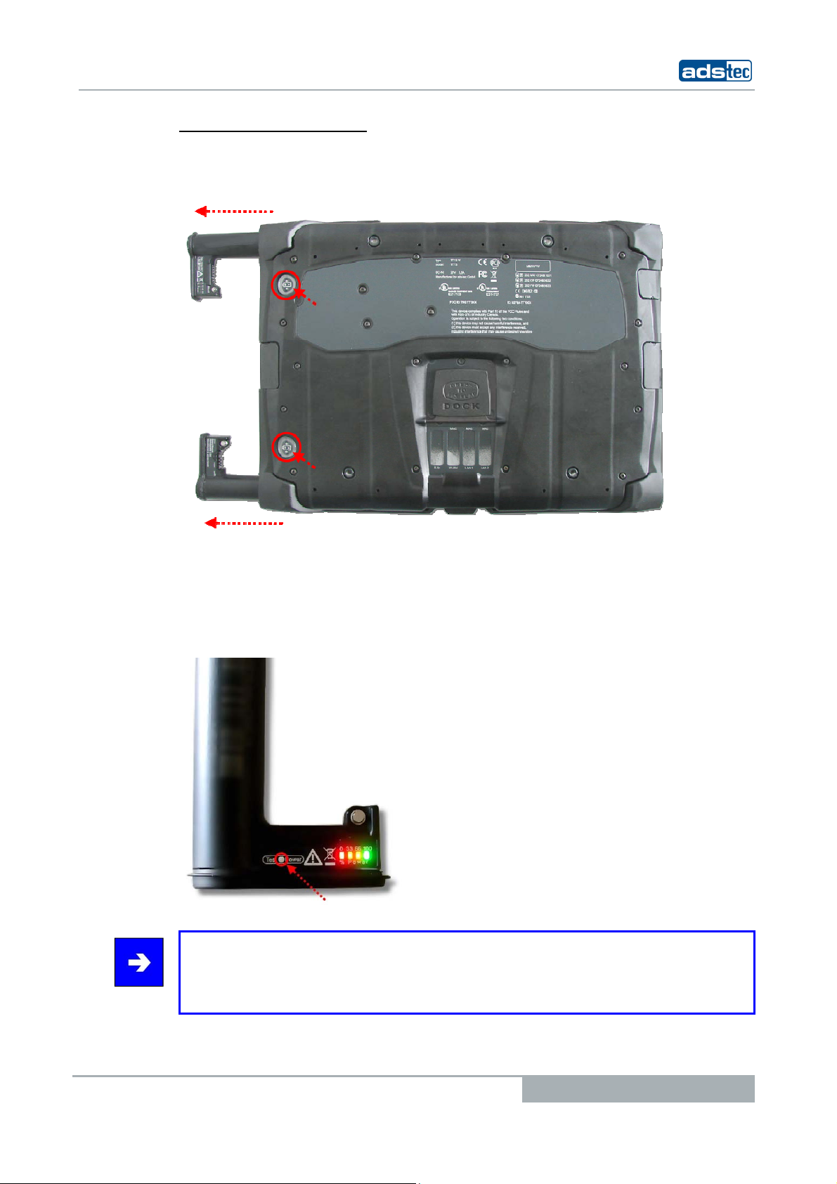
B
ATTERY STATUS REPLACEMENT
The TT13 batteries can be removed by using a mechanical ejector on the back of the
device.
The batteries status can be retrieved by pushing a button on the batteries. The batteries
display will light up for a few seconds and show the current batteries charge status on a
scale from 0 to 100. If the display lights red, this represents a weak battery. If the display
is green, it shows that the battery is fully charged. If the device is in operating mode, the
battery status can be retrieved by using the supplied Battery Information & Diagnostics
Tool.
Note:
The "Hardware specific software” chapter describes the Battery Information &
Diagnostics Tool, which can be used for retrieving the accumulator status while operating
the unit.
© ads-tec GmbH • Raiffeisenstr.14 • 70771 Leinfelden-Echterdingen
19
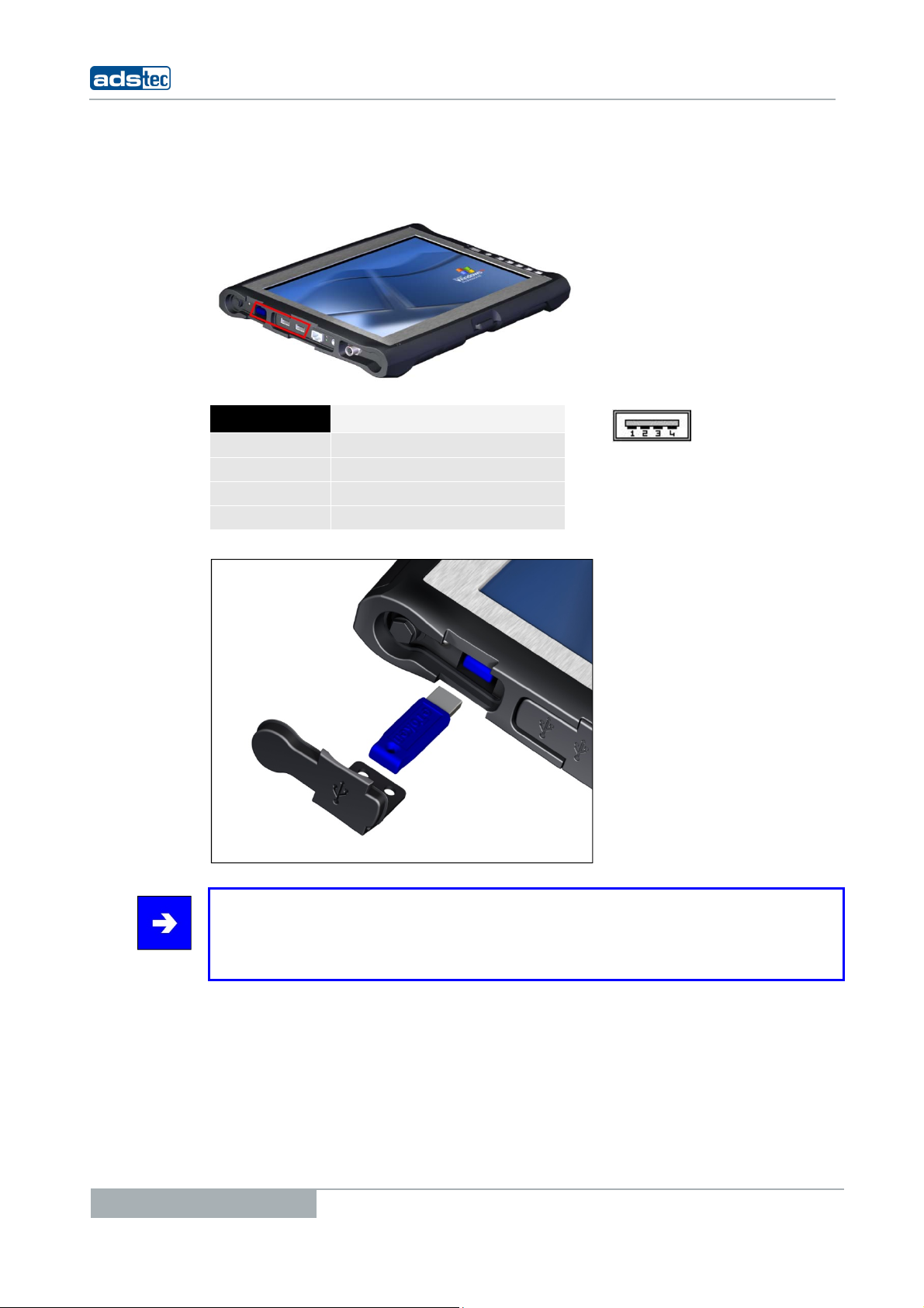
5.3 USB CONNECTIONS
The USB interfaces are used for connecting peripherals with USB connection. The
interfaces comply with the USB 2.0 standard.
PIN NUMBER SIGNAL NAME
1
2
3
4
VDC
D D+
GND
Tablet PCs TT13
20
Note:
The two side USB ports together have a current limit of 1.5A. This allows trouble-free
operation of external devices, like an external DVD drive. The in-depth USB interface is
designed according to the standard for 0.5A.
© ads-tec GmbH • Raiffeisenstr.14 • 70771 Leinfelden-Echterdingen
Tablet PCs TT13
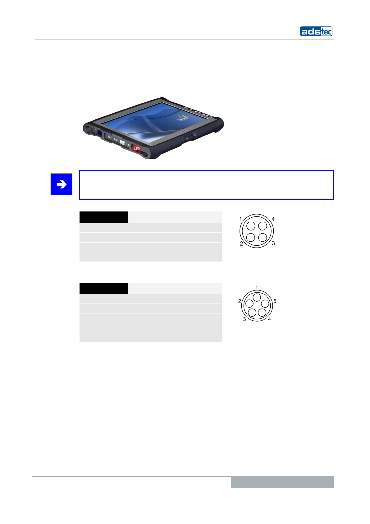
5.4 ODU-INTERFACE (OPTIONAL)
By using the SD Connector, the device can be connected to an Ethernet network (10/100
Mbit). Data throughputs of 10MB can be achieved with a maximum cable length of 5m.
Note:
This interface does not allow booting via the network. If you want to boot the device via
the network connection, we recommend using the LAN interface.
PIN-OUT: (LAN)
PIN-NUMBER SIGNAL NAME
1
2
3
4
RxD+
RxD-
TxD+
TxD-
IN-OUT: USB
P
PIN-NUMBER SIGNAL NAME
1
2
3
4
5
Data-
Data+
GND
VCC
NC
© ads-tec GmbH • Raiffeisenstr.14 • 70771 Leinfelden-Echterdingen
21
Tablet PCs TT13
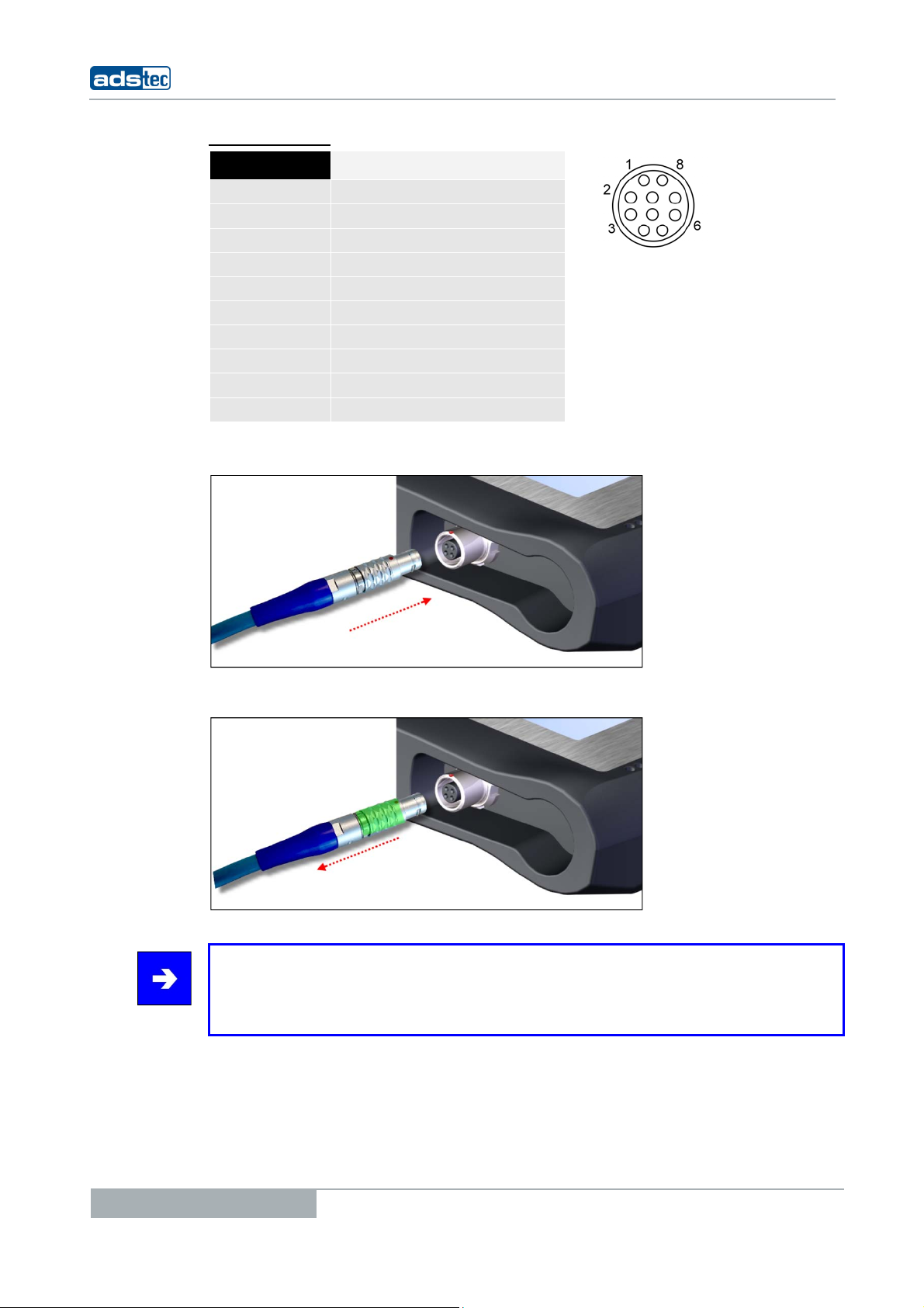
PIN-OUT: RS232
PIN-NUMBER SIGNAL NAME
1
2
3
4
5
6
7
8
9
10
DCD
RxD
TxD
DTR
GND
DSR
RTS
CTS
RI
NC
The SD Connect cable must be connected so that the red markers match.
For disconnecting the SD Connect cable, it must be pulled rearwards in the area marked in
green. This loosens the snap-in mechanism at the end of the plug.
Note:
The interface is always shown in the network connections, even if the interface is not
available regarding the configuration of the device. Functionality is only given, when a
interface is available.
22
© ads-tec GmbH • Raiffeisenstr.14 • 70771 Leinfelden-Echterdingen
Tablet PCs TT13
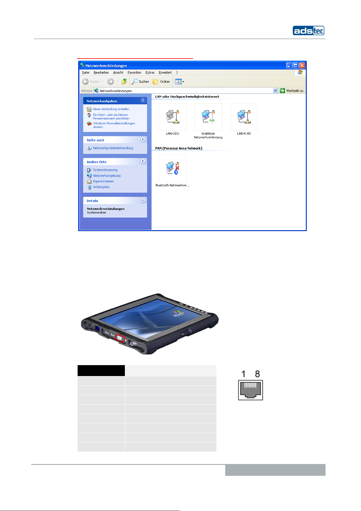
VIEW: NETWORK CONNECTION (EXEMPLARY)
5.5 NETWORK CONNECTION (RJ45)
If the drivers required for functioning are installed on the device, the control system may
be integrated in an Ethernet network supporting the 10/100 Mbit standard by using the
Ethernet 10/100BaseT network connector. Specifications of this network topology must be
observed in this case.
PIN NUMBER SIGNAL NAME
1
2
3
4
5
6
7
8
TX +
TX -
RX +
NC
NC
RX -
NC
NC
© ads-tec GmbH • Raiffeisenstr.14 • 70771 Leinfelden-Echterdingen
23
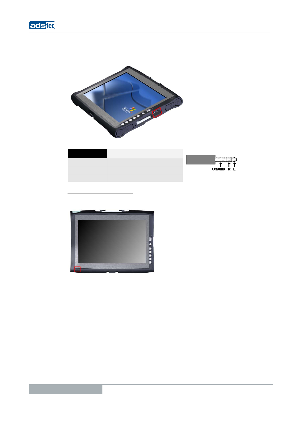
5.6 MIC
IN
Tablet PCs TT13
An external microphone can be connected via the MIC IN socket on the device by means
of a 3.5mm cinch cable.
PIN NUMBER SIGNAL NAME
Ground
R
L
Signal, right-hand side
GND
Signal, left-hand side
ICROPHONE IN FRONT PANEL
M
Additionally, the device has an internal microphone in the front panel. This microphone can
be configured by using the volume control integrated in the operating system.
24
© ads-tec GmbH • Raiffeisenstr.14 • 70771 Leinfelden-Echterdingen
Tablet PCs TT13
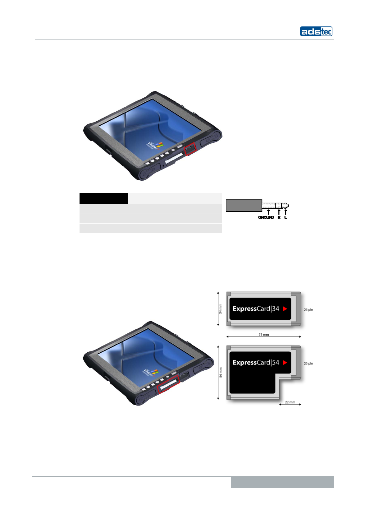
5.7 L
INE OUT
By using the Line Out socket of this device and connecting via a 3.5mm cinch cable, a
stereo audio signal can be output to earphones or to external speakers.
PIN NUMBER SIGNAL NAME
Ground
R
L
GND
Signal, right-hand side
Signal, left-hand side
5.8 E
XPRESSCARD SLOT
The device is equipped with an ExpressCard slot, which supports the following ExpressCard
types.
© ads-tec GmbH • Raiffeisenstr.14 • 70771 Leinfelden-Echterdingen
25
6 SOFTWARE & DRIVER INSTALLATION
The device will be delivered with a pre-installed Windows operating system on request by
the customer. The drivers required for this are already installed and the operating system
will be enabled by entering the licence information. Should an initial installation be
required, please follow the following steps. With a newer operating system like Windows
XP, the network card and graphics card will properly be recognised during the initial
installation, so that only the touchscreen driver and the soft keyboard must be installed
separately.
Note:
If the hard drive was formatted, the operating system can be reinstalled by using one of
the existing interfaces.
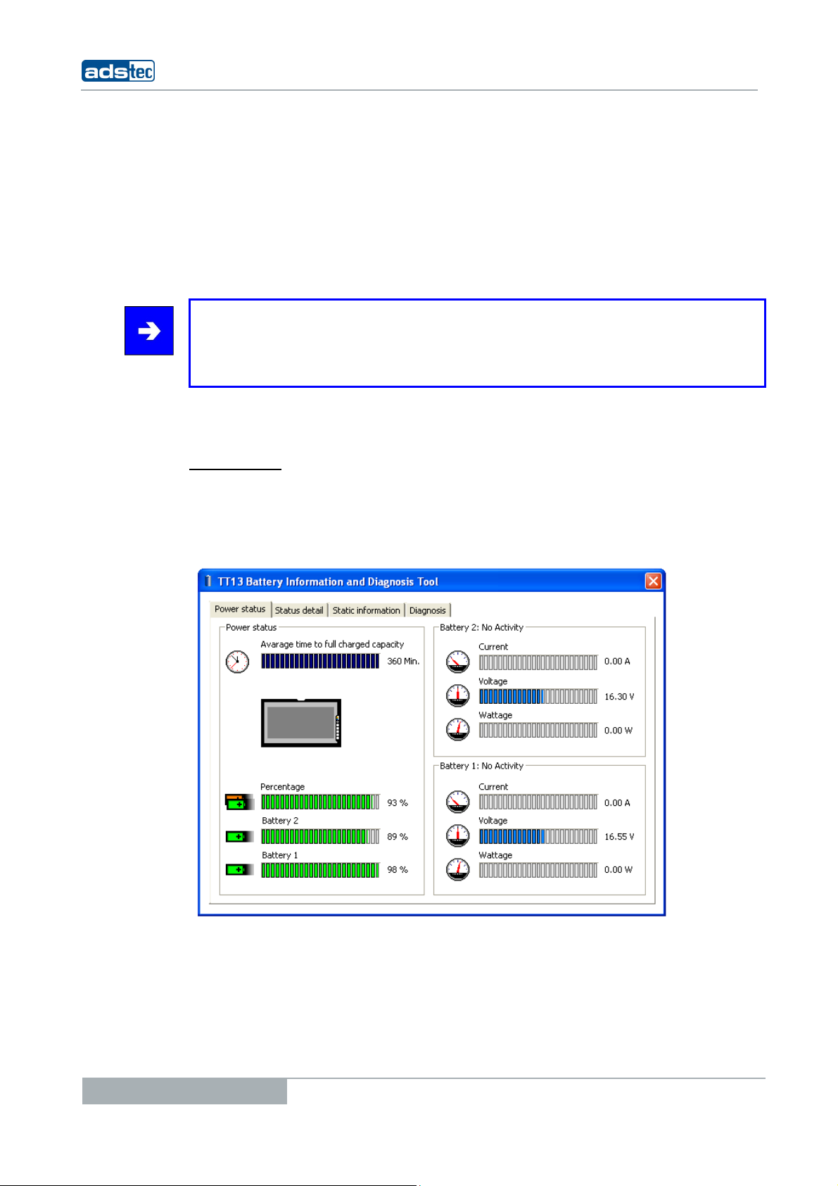
6.1 BATTERY INFORMATION & DIAGNOSTICS TOOL
An external keyboard is required for installation.
OWER STATUS
P
The starting page of the battery information tool gives information about the current
accumulator charge status. The lithium-ion accumulators are charged alternately with the
20V power adapter connected. The charging progress is displayed on the right hand side
for both accumulator slots. The status display on the left shows the remaining accumulator
charging time.
Tablet PCs TT13
26
© ads-tec GmbH • Raiffeisenstr.14 • 70771 Leinfelden-Echterdingen
Tablet PCs TT13
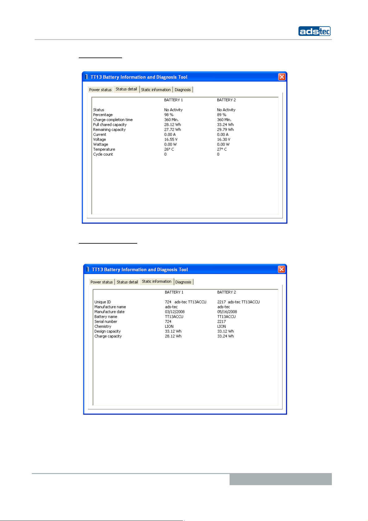
STATUS DETAILS
The Status Detail page lists all starting page data in a table.
TATIC INFORMATION
S
The "Static Information" tab displays all detail information, e.g. the manufacturer, and the
capacity of the lithium-ion accumulator.
© ads-tec GmbH • Raiffeisenstr.14 • 70771 Leinfelden-Echterdingen
27
 Loading...