

ADS-TEC RAP1000, RAC1000 Quick Start Guide
1. Connecting the device
1.1. Opening the service slot cover
The service slot must be opened with a Phillips screw
driver in order to put the device into operation.
1.2. Power supply connection
24V DC / 230V AC / PoE
The power for this device can be supplied by a 24V DC (2
pin plug), or as an option, via a 230V AC (3 pin plug) or by a
PoE connector.
The corresponding COMBICON connectors are included in
the scope of delivery.
Connect the device with a suitable power supply unit.
1.3. RJ45 network cable connection
For initial commissioning it is essential to establish a
connection between this device and a PC by using a RJ45
network cable.
To connect the device with a PC:
Device host connector <-> PC LAN connector
1.4. Antennae installation
The four or eight antennas supplied with the device work in
the 2.4GHz or in the 5GHz frequency range (two or four
each).
One to two antennas of the same type are required for each
WLAN module for establishing a radio connection.
Depending on the equipment, one or two WLAN modules
can be operated in parallel.
Install the antennas at the device.
Note:
We would recommend to make use of our website
contents (www.ads-tec.de) in order to ensure an
optimised data quality and to be quickly and
comprehensively informed of any technical
modification.
2. Network adapter configuration /
Opening the web interface
2.1. PC-LAN network adapter configuration
(explained on the example of configuration under Windows XP®)
Open the Properties tab of the network adapter used. The
directory path is:
Start> Settings> Network connections>
LAN connection> Properties
Select the following option in the pop-up dialogue:
Internet protocol (TCP/IP); then click on "Properties"
Here select the following item:
"Use following IP address"
Access to the device is only enabled once the following
parameters have been entered:
IP address: 192.168.0.100
(The last section of digits must repre sent a number between 1 and 253;
the value “100“ was selected in the example)
Once the IP address was entered, you have to input the
"Subnet mask" address.
If you click into the "Subnet mask" box, the correct
address is automatically entered.
Subnet mask: 255.255.255.0
You can now close the dialogue boxes by pushing the "OK"
button.
2.2. WLAN network adapter configuration
Repeat the configuration steps of 2.1) with the exception,
that the IP address must not be identical, in order to
configure the WLAN network adapter.
IP address: 192.168.0.200
(The last section of digits must include a number betwee n 1 and 253;
the value “200” was selected in the example)
2.3. Opening the device web interface
Start your web browser in order to open the web interface
of this device. Now, enter the following IP address into the
address line of your browser and confirm it with "Enter":
http:\\192.168.0.254
2.4.Login
In the Login prompt window, the default settings must be
entered.
The default settings, as delivered to the customer, are:
User name: admin
Password: admin
Confirm your entry by pushing "OK".
Now the device web interface will appear.
Quick Start Guide Commissioning RAP/RAC1000 series
3. Configuration of WLAN module(s) 4. Establishing a connection with the WLAN network
3.1. Enabling the WLAN module
In order to enable the WLAN module(s), you have to switch
to the following web interface page:
WLAN device > Interfaces
Depending on the device equipment options there are one
or two WLAN modules available.
Enable the desired WLAN module by ticking the "Enable
interfaces" checkbox in the web interface.
3.2. WLAN module configuration
Operational mode:
The operational mode must be defined for the device.
Available are: Access Point or Client
Network name (SSID):
The SSID represents the name of the WLAN radio network.
The default setting is: ads
Any name can be assigned for the network ID.
WLAN mode:
Select the WLAN mode you prefer:
Warning:
Please use the WLAN mode actually
supported by your WLAN subscribers.
Regulatory domain:
Select your location.
Warning:
Adherence to settings with the applicable
requirements by the regulatory authority and
observance of valid antenna amplification
limits is the responsibility of the
operator/operating company.
Channel: The default setting is: Auto
The device automatically selects the optimum setting.
3.3. Saving the settings
The changes you made must finally be activated or saved.
In order to do this, click on the menu item:
Settings> Configuration> General
Click on "Save" in the window that appears now. The current
configuration is now transmitted and saved.
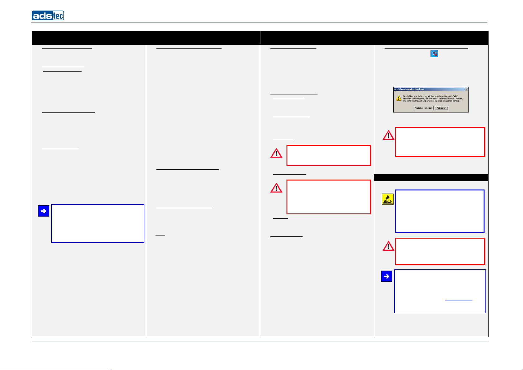
4.1. Establishing a connection with the WLAN network
Click on the WLAN icon in your taskbar in order to
establish a radio connection with the device.
All available WLAN networks are displayed.
Select the radio network with the assigned SSID and
click on "Connect".
The following warning will appear:
You have to select "Connect anyway" in order to
establish a connection with the WLAN network.
Warning:
The current WLAN connection is not encrypted.
We recommend using an encryption method.
You'll find further information on the issue of
5. Security instructions
encryption in the manual.
Note:
Please observe applicable security measures
when handling electronic components sensitive
to electrostatic charges.
(DIN EN61340-5-1 / DIN EN 61340-5-2).
Warning:
Any installation works on the device is only
permitted if the power supply is switched off,
and handling the device is safe.
Note:
Hereby, ads-tec GmbH, declares that this WLAN
Access Point / Access Client is in compliance with
the essential requirements and other relevant
provisions of Directive 1999/5/EC. The declaration
of conformity is available at www.ads-tec.de in
the download area.
1
110513_ QUICK START GUIDE RAP_RAC1000_EN_DZ-HAND-91015-1 V1.3
© ads-tec GmbH • Raiffeisenstr.14 • 70771 Leinfelden-Echterdingen
Quick Start Guide Mounting RAP/RAC1000 series
1. Fixing the installation bracket 2. Connecting the supply cables 3. Routing cables through grommets 5. Drill template (1:1)
1.1. Bracket installation
The installation bracket is fixed to the device in the state
of delivery.
a) Loosen the Allen screws (M4x12) in order to fix the
device at the selected position. (1)
b) Fix the installation bracket excluding the device at
position you have selected. Make sure that the
installation bracket is securely fixed with a minimum
of two screws on opposite ends.
2.1. Opening the service slot cover
The service slot must be opened in order to install the
cables. Remove the five screws indicated by arrows
(M3x8).
3.1. Cable installation
Existing grommets are used for cable protection and in
order to ensure compliance with the IP65 protection
class.
Insert the connected cables into the grommets so that
the grommets fully enclose the cables.
c) Attach the device to the fixed installation bracket and
ensure that device and installation bracket is flush.
Fix the device on the installation bracket by using both
Allen screws previously removed. (1)
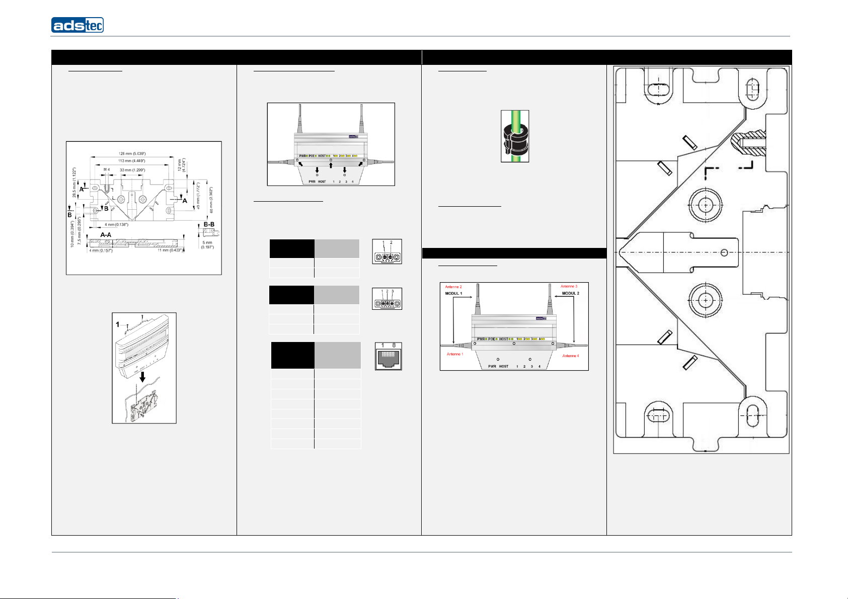
2.2. Power supply connection
The power for this device can be supplied by a 24V DC (2
pin plug), or as an option, via a 230V AC (3 pin plug) or by
a PoE connector.
24 V DC power supply
PIN NUMBER SIGNAL NAME
110/230V AC power supply
PIN NUMBER SIGNAL NAME
PoE (Power over Ethernet)
The PWR LED will continuously light green as soon as the
power supply is connected with the device.
For initial commissioning it is essential to establish a
connection between this device and a PC by using a RJ45
network cable.
To connect this device with a PC: Device host connector <> PC LAN connector
1 24V DC
2 N
1 L
2 PE
3 N
PIN
NUMBER
1 TX +
2 TX -
3 RX +
4 PoE/G
5 PoE/G
6 RX -
7 PoE/-48V
8 PoE/-48V
SIGNAL
NAME
3.2. Closing the service slot
4. Montage der Antennen
4.1. Antennae installation
Select the grommet size in accordance with the
corresponding cable diameter.
Then put the cable, including the grommet, in the recess
provided for it.
Make sure that all grommets are properly seated in the
recesses provided for them.
Now close the service slot and fix it using the previously
removed screws (M3x8).
Two antennas should be installed for operating a WLAN
module.
The device is capable of operating two modules for
different WLAN networks in parallel mode.
The correct antenna installation for one module includes
one horizontally aligned and one vertically aligned
antenna.
The four or eight antennas supplied with the device work
in the 2.4GHz or in the 5GHz frequency range (two or four
each).
Install the antennas at the device.
2
110513_ QUICK START GUIDE RAP_RAC1000_EN_DZ-HAND-91015-1 V1.3
© ads-tec GmbH • Raiffeisenstr.14 • 70771 Leinfelden-Echterdingen
 Loading...