

ADS-TEC RAP1000, RAC1000 User Manual

Version 4.2
User Manual
IT Infrastructure
RAP/RAC1000
Product Portfolio
IT Infrastructure RAP/RAC1000
Copyright
© ads-tec GmbH
Raiffeisenstr.14
D-70771 Leinfelden-Echterdingen
Germany
HIGH RISK APPLICATION HAZARD NOTICE
Unless otherwise stated in the product documentation, the device is not provided with error-tolerance capabilities and cannot therefore
be deemed as being engineered, manufactured or setup to be compliant for implementation or for resale as an online surveillance
device in environments requiring safe, error-free performance, e.g. for implementation in nuclear power plants, aircraft navigation,
communication systems, or air traffic control, life saving and military facilities whereby possible device failures might result in death,
personal injuries, or serious physical and/or environmental damages (i.e. all applications involving high-risk hazard factors). This is
therefore to state that neither ads-tec nor any ads-tec sub-supplier do not hereby undertake any warranty of fitness and/or liability
whatsoever, be it by express or by tacit consent, in as far as the suitability of the Firewall to high-risk application hazards is concerned.
2
© ads-tec GmbH • Raiffeisenstr.14 • 70771 Leinfelden-Echterdingen

IT Infrastructure RAP/RAC1000
INDEX
ABOUT US .......................................................................................................................................... 6
1
NOTES ..................................................................................................................................... 7
RELEVANT UNIT DOCUMENTATION .................................................................................................... 7
1.1
DESCRIPTION OF THE WARNING SYMBOLS USED IN THIS GUIDE ................................................................. 7
1.2
1.3
DATA, IMAGES, AMENDMENTS AND VARIATIONS ................................................................................... 7
TRADEMARKS .............................................................................................................................. 7
1.4
1.5
COPYRIGHT ................................................................................................................................ 8
STANDARDS ................................................................................................................................ 8
1.6
OPERATING AND SAFETY INSTRUCTIONS ........................................................................................ 9
2
2.1
SAFETY INSTRUCTIONS .................................................................................................................. 9
UNIT OPERATION SITE ................................................................................................................ 10
2.2
2.3
DAMAGES DUE TO IMPROPER USE ................................................................................................... 10
WARRANTY / REPAIRS ................................................................................................................. 10
2.4
GENERAL DIRECTIONS FOR THE 5GHZ VERSION (802.11 A / 802.11 H) ETSI ........................................ 10
2.5
2.6
ANTENNA LIST FOR USE IN USA AND CANADA / FCC ........................................................................... 11
CHANNEL LIST FOR USE IN USA AND CANADA / FCC ........................................................................... 12
2.7
2.8
WLAN INSTRUCTIONS ................................................................................................................ 12
INTRODUCTION ....................................................................................................................... 13
3
3.1
RAP AND RAC VERSIONS ............................................................................................................. 14
SCOPE OF SUPPLY ...................................................................................................................... 16
3.2
ENVIRONMENTAL CONDITIONS ....................................................................................................... 16
3.3
4
MOUNTING ............................................................................................................................. 17
MOUNTING CONDITIONS .............................................................................................................. 17
4.1
4.2
EXTERIOR DEVICE DIMENSIONS ..................................................................................................... 17
MOUNTING DIAGRAM .................................................................................................................. 19
4.3
DEVICE MOUNTING ..................................................................................................................... 20
4.4
4.5
CONNECTING SUPPLY LINES .......................................................................................................... 21
ANTENNA ASSEMBLY ................................................................................................................... 23
4.6
5
SYSTEM FEATURES ................................................................................................................... 24
LED STATUS INDICATORS ............................................................................................................ 24
5.1
5.2
LED STATUS INDICATORS DURING OPERATION .................................................................................. 25
INTERFACE OVERVIEW ................................................................................................................. 28
5.3
Po wer Supply 24V DC .............................................................................................................. 28
5.3.1
Po wer Supply 110/230 VAC ..................................................................................................... 29
5.3.2
5.3.3
Po wer Supp l y HOST (IEEE 802.AF) ......................................................................................... 29
5.3.4
Fibre Optic Ethernet .................................................................................................................. 29
5.3.5
SIM Card Reader, ISO 7816-compatible .................................................................................. 30
6
INITIAL DEVICE OPERATIONS .................................................................................................... 31
6.1
FIRST-TIME CONFIGURATION ........................................................................................................ 31
MANUAL NETWORK ADAPTER CONFIGURATION VIA RJ45/OPTICAL CABLE ................................................. 31
6.2
WLAN NETWORK ADAPTER CONFIGURATION .................................................................................... 33
6.3
© ads-tec GmbH • Raiffeisenstr.14 • 70771 Leinfelden-Echterdingen
3

6.4 FIRST-TIME CONFIGURATION VIA WEB INTERFACE ............................................................................. 35
WIRELESS NETWORK CONFIGURATION ............................................................................................ 36
6.5
6.6
ESTABLISHING A WIRELESS NETWORK CONNECTION ........................................................................... 36
ACCESS POINT SETUP WIZARD .................................................................................................. 37
7
FIRST-TIME CONFIGURATION USING THE SETUP WIZARD ..................................................................... 37
7.1
7.1.1
Lang uag e Sel ectio n .................................................................................................................. 37
7.1.2
IP Configuration ........................................................................................................................ 38
7.1.3
WLAN-1 Configuration ............................................................................................................. 40
7.1.4
WLAN-1 Security ...................................................................................................................... 43
Changing the Password ........................................................................................................... 46
7.1.5
7.2
CONFIGURATION USING THE FILTER WIZARD .................................................................................... 48
Adding a Rule set ..................................................................................................................... 48
7.2.1
7.2.2
Changing and Searching existing Rule Sets ............................................................................ 49
7.2.3
Loading pre-configured Rul e sets ............................................................................................ 50
Definition of a new Rule set on Layer 2 ................................................................................... 52
7.2.4
7.2.5
Definition of a new Rule set on Layer 3 ................................................................................... 62
8
ACCESS POINT/CLIENT WEB INTERFACE ..................................................................................... 75
DIAGNOSTICS MAIN MENU ITEM ..................................................................................................... 75
8.1
8.1.1
System status ........................................................................................................................... 75
8.2
GENERAL OVERVIEW FOR CONFIGURATION IN THE MENUS ..................................................................... 76
IP routing exemplary configuration ........................................................................................... 77
8.2.1
Error messages ........................................................................................................................ 79
8.2.2
8.2.3
Eventlog .................................................................................................................................... 80
8.2.4
ICS-Status ................................................................................................................................ 81
8.2.5
HOST ........................................................................................................................................ 81
8.2.6
Ping test .................................................................................................................................... 82
8.2.7
Remote Capture ....................................................................................................................... 83
MAIN MENU ITEM CONFIGURATION ................................................................................................. 83
8.3
IP configuration ......................................................................................................................... 83
8.3.1
8.3.2
WLAN-1 Parameter .................................................................................................................. 90
8.4
WLAN-1 SECURITY ................................................................................................................... 98
8.5
STATIC MAC ADDRESS .............................................................................................................. 102
FILTER WIZARD ....................................................................................................................... 104
8.6
8.7
BASIC SETTINGS ...................................................................................................................... 105
Access Authorization .............................................................................................................. 110
8.7.1
8.7.2
Adv. WLAN ............................................................................................................................. 114
8.7.3
Sonstiges ................................................................................................................................ 118
Network .................................................................................................................................. 119
8.7.4
8.7.5
Service .................................................................................................................................... 126
8.8
PRIORITISATION ...................................................................................................................... 132
SYSTEM ................................................................................................................................. 134
8.9
8.9.1
Backup settings ...................................................................................................................... 134
8.9.2
Factory defaults ...................................................................................................................... 138
8.10
INFORMATION ...................................................................................................................... 140
8.10.1
General ............................................................................................................................... 140
8.10.2
Technical data ..................................................................................................................... 141
IT Infrastructure RAP/RAC1000
4
© ads-tec GmbH • Raiffeisenstr.14 • 70771 Leinfelden-Echterdingen

IT Infrastructure RAP/RAC1000
8.10.3 Hardware installation ........................................................................................................... 142
8.10.4
Local diagn os tics ................................................................................................................. 142
8.10.5
Sitemap ................................................................................................................................ 143
9
REGULATORY APPROVALS ....................................................................................................... 144
9.1
EUROPEAN APPROVALS .............................................................................................................. 144
CHANNELLISTS ........................................................................................................................ 146
9.2
9.4
5 GHZ DFS REGULATION AFTER ETSI EN 301 893 V1.4.1 WITHIN THE EU .................................. 154
FCC-APPROVAL ....................................................................................................................... 155
9.5
DIRECTIVES ............................................................................................................................ 156
9.6
10
TECHNICAL DETAILS............................................................................................................... 157
RAP AND RAC VERSIONS ........................................................................................................ 157
10.1
10.2
ETHERNET DATA TRANSMISSION ............................................................................................... 157
RADIO PROPERTIES ............................................................................................................... 158
10.3
POWER SUPPLY .................................................................................................................... 158
10.4
10.5
CONFIGURATION ................................................................................................................... 158
GENERAL DATA .................................................................................................................... 158
10.6
11
SERVICE AND SUPPORT ........................................................................................................... 159
ADS-TEC SUPPORT ................................................................................................................. 159
11.1
11.2
COMPANY ADDRESS ............................................................................................................... 159
EXAMPLES OF USE .................................................................................................................. 160
12
PRIORITIZATION ................................................................................................................... 160
12.1
12.2
CERTIFICATES ...................................................................................................................... 163
SIM CARD .......................................................................................................................... 187
12.3
12.4
USB PRINTER ...................................................................................................................... 189
OVERVIEW OF CLIENT OPERATION MODES .................................................................................. 191
12.5
EXTENDED BACKGROUND SCANNING AND ROUTER ......................................................................... 193
12.6
12.7
SEAMLESS ROAMING .............................................................................................................. 197
EXTENDED BACKGROUND SCANNING .......................................................................................... 202
12.8
12.9
EXTENDED ROAMING PARAMETERS ............................................................................................ 205
REMOTE CAPTURE ................................................................................................................. 210
12.1
CERTIFICATION BRASIL .......................................................................................................... 214
12.1
© ads-tec GmbH • Raiffeisenstr.14 • 70771 Leinfelden-Echterdingen
5
S
8
8
-
p
p
d
g
l
u
tec GmbH • Raiffeisenstr
8
8
g
r
t
g
g
A
BOUT U
IT Infrastr
cture RAP/RAC1000
ads-tec GmbH
Raiffeisenstr. 14
D-70771 Leinfelde
Tel: +49 711 45
Fax: +49 711 45
www.ads-tec.com
n-Echterdingen
94-0
94-990
ads-tec GmbH pro
technology, up-to
technology, data
ads-tec GmbH im
specialized in han
The data systems
e of industrial
ran
ads-tec is specia
develops software
vides lar
date know-how and comprehensive services in
rocessing technology and systems engineering.
lements full automation solutions from planning
ling and material handling technologies.
division develops and produces PC based solu
PCs, thin clients and embedded systems.
ized in modifying and optimizing embedded
tools to complement its hardware platforms.
e enterprises and globally active corpo
ations with cutting edge
the area of automation
to commissionin
ions and offers a broad
operatin
systems and
and is
6
© ads-
-Echterdingen
IT Infrastructure RAP/RAC1000
1 NOTES
1.1 RELEVANT UNIT DOCUMENTATION
The following documents are essential to unit setup and operation:
SER MANUAL (THIS DOCUMENT)
U
Contains information on mounting, placing into operation and operation of the unit, further
to technical data on unit hardware.
S
ERVICE CD:
Contains th e User Manu al, the Asse mbly Guide, the Quick I nstall Guid e and Tool.
1.2 DESCRIPTION OF THE WARNING SYMBOLS USED IN THIS GUIDE
Contains the User Manual, the Assembly Guide, the Quick Install Guide and Tools.
Warning:
The “Warning” symbol precedes warnings on uses or operations that might either lead to
personal injury and/or hazards, or to any hardware and software damages.
Note:
This Symbol indicates special notes, terms and/or conditions that strictly need to be
observed to ensure optimised and/or zero-defect operations. It also precedes tips and
suggestions for efficient unit implementation and software optimisation.
1.3 DATA, IMAGES, AMENDMENTS AND VARIATIONS
All texts, data and figures are non-binding. We reserve the right of modification in
accordance with technological progress. At that point in time when the products leave our
premises, they comply with all currently applicable legal requirements and regulations. The
operator/operating company is independently responsible for compliance with and
observance of any subsequently introduced technical innovations and new legal
requirements, as well as for all usual obligations of the operator/operating company.
1.4 TRADEMARKS
It is hereby notified that any software and/or hardware trademarks further to any
company brand names as mentioned in this User’s Guide are all strictly subject to the
various trademark, brand name and patent protection rights.
®
Windows
®
Intel
, Pentium®, Atom™ , Core™2 are registered trademarks of Intel Corp.
CompactFlash™ and CF™ are registered trademarks of SanDisk Corp.
®
RITTAL
is a registered trademark of the Rittal Werk Rudolf Loh GmbH & Co. KG.
Any further additional trademarks and/or brand names herein, be they domestic or
international, are hereby duly acknowledged.
, Windows® CE are registered trademarks of Microsoft Corp.
®
, PS/2® and VGA® are registered trademarks of IBM Corp.
IBM
© ads-tec GmbH • Raiffeisenstr.14 • 70771 Leinfelden-Echterdingen
7

1.5 COPYRIGHT
1.6 STANDARDS
IT Infrastructure RAP/RAC1000
This User’s Guide inclusive of all the images it contains is entirely proprietary and subject
to copyright. Any irregular use of this Guide by third parties infringing copyright terms is
thus strictly forbidden. Reproduction, translation, as well as electronic and photographic
image storage and/or amendment processes, are subject to prior written authorisation
directly by M/s. ads-tec GmbH.
Any violation and infringement thereto will be held liable for compensation of all damages.
This unit is compliant with the provisions and safety objectives of the following EU
Directives:
• This unit is compliant with the CE mark testing specification limits as defined in the
European test standards EN 61000-6-4 und EN 61000-6-2
• This unit is compliant to the DIN EN 60950 (VDE0805, IEC950) testing
specification limits on “Safety of Information Technology Equipment”
• This unit is compliant to the DIN EN 60068-2-6 (sinusoidal vibration) testing
specification limits
• This unit is compliant to the DIN EN 60068-2-27 (shock and bump) testing
specification limits
Note:
A corresponding declaration of conformity is available for competent authorities, care of
the Manufacturer. Said declaration can be viewed at all times upon request.
For full compliance to the legal requirements in force on electromagnetic compatibility, all
components and cables used for unit connection must also be compliant with said
regulations. It is therefore necessary to employ BUS and LAN cables featuring screened
plug connectors, to be strictly installed as per the instructions contained in the User
Manual.
8
© ads-tec GmbH • Raiffeisenstr.14 • 70771 Leinfelden-Echterdingen
IT Infrastructure RAP/RAC1000
2 OPERATING AND SAFETY INSTRUCTIONS
The unit operates under electrical tension and implements supersensitive component parts.
Intervention by the User is required only for power supply line connection operations.
Should any further alterations be required, it is necessary to consult either with the
Manufacturer directly or with authorised service personnel accordingly. During said
connection operations, the unit must be completely powered down. Specific requirements
need to be met concerning the prevention of electrostatic discharge on component
construction parts during contact. If the unit is opened up by a non authorised individual,
the User may be subject to potential hazards and, warranty conditions are terminated.
General Instructions:
• This User’s Guide must be read and understood by all Uses and must be available
for consultation at all times
• Mounting, operation start-up and unit operation must only be conducted by
appropriately qualified and trained personnel
• All individuals and operators using the unit must strictly observe all safety and use
instructions as provided within the User’s Guide
• All regulations and prescriptions on accident prevention and safety in force at the
unit installation site must be strictly observed at all times
• This User’s Guide provides all the most important directions as required for safe
and security oriented operation
• Safe and optimised unit operations are subject to appropriate storage, proper
transport and handling, accurate unit setup, start-up and operation
Note:
Only original ads-tec firmware / software is allowed for any of the adjustments and
features described in this User’s Guide. Deployment of any firmware / software that has
not been released by ads-tec will terminate all warranty conditions.
2.1 SAFETY INSTRUCTIONS
Warning:
In order to prevent possible unit damages, all cable lines (power supply, interface cables)
must be hooked up strictly with the unit in power-OFF conditions.
Warning:
All unit mounting operations must be strictly conducted under safe, secure and zeropotential conditions.
Note:
When handling parts and components susceptible to electrical discharge, please
accurately observe all the relevant safety provisions.
(DIN EN 61340-5-1 / DIN EN 61340-5-2)
© ads-tec GmbH • Raiffeisenstr.14 • 70771 Leinfelden-Echterdingen
9
2.2 UNIT OPERATION SITE
This unit is engineered for industrial application. It is necessary to ensure that specified
environmental conditions are maintained at all times. Unit implementation in non-specified
surroundings, i.e. onboard ships, in explosive atmospheres or at extreme heights, is
prohibited.
Warning:
For the prevention of water condensate accumulation, the unit should be turned ON only
when it reaches ambient temperature. This particularly applies when the unit is subject to
extreme temperature fluctuations and/or variations.
Avoid overheating during unit operations; the unit must not be exposed to direct sunlight
or any other direct light or heat sources.
Warning:
This is a Class A device. In a domestic environment this device may cause radio
frequency (RF) interference, in which case the user may be required to take adequate
measures.
Warning:
If the unit is operated in outdoor locations, a lightning conductor needs to be present
within capture range. Ensure that all incoming conductive systems are equipped with
equipotential bonding.
IT Infrastructure RAP/RAC1000
2.3 DAMAGES DUE TO IMPROPER USE
Should the service system have evident signs of damages incurred e.g. due to wrong
operation or storage conditions or due to improper unit use, the unit must be
decommissioned or scrapped. Ensure that it is protected against accidental start-up.
2.4 WARRANTY / REPAIRS
During the unit warranty period, any repairs thereto must strictly be conducted solely by
the manufacturer or by service personnel that has been duly authorised by the
manufacturer.
2.5 GENERAL DIRECTIONS FOR THE 5GHZ VERSION (802.11 A / 802.11 H) ETSI
• The unit is certified for use of the 5 GHz band in accordance with ETSI EN 301 893
V1.3.1. Users need to observe the following:
• Access Point as well as Access Client units make use of DFS and TPC as standard on all
5 GHz channels, in indoor as well as in outdoor configuration. This means that the
devices may always be operated at a maximum transmission power of 23 dBm or 30
dBm, respectively.
Note:
Access Points must not switch off DFS in outdoor locations. Access Clients may switch off
DFS, though. This setting is turned off by default.
• 802.11a channels cannot be set to static values.
10
© ads-tec GmbH • Raiffeisenstr.14 • 70771 Leinfelden-Echterdingen
IT Infrastructure RAP/RAC1000
Note:
The lower 4 channels (non-DFS) can be set to static values if DFS is turned off. Turning
off DFS will however also make the features 60s Scan and Radar Detection unavailable.
• When activating the Access Point, the unit will perform an initial Radar Detection Scan
during which it will wait 60 seconds for a radar impulse on a randomly chosen channel.
Subsequently, it will start operating on this channel.
• If an Access Client detects a radar impulse during operation, the Access Point will be
notified of this via 802.11h. Triggered by this or its own detection of the impulse, the
Access Point will subsequently perform a channel switch to 802.11h. The connection
loss in this case is usually less than 80ms.
• The maximum permissible transmission power is different for each channel. Hence
users are required to correctly set the antenna amplification in case the standard
antenna is replaced!
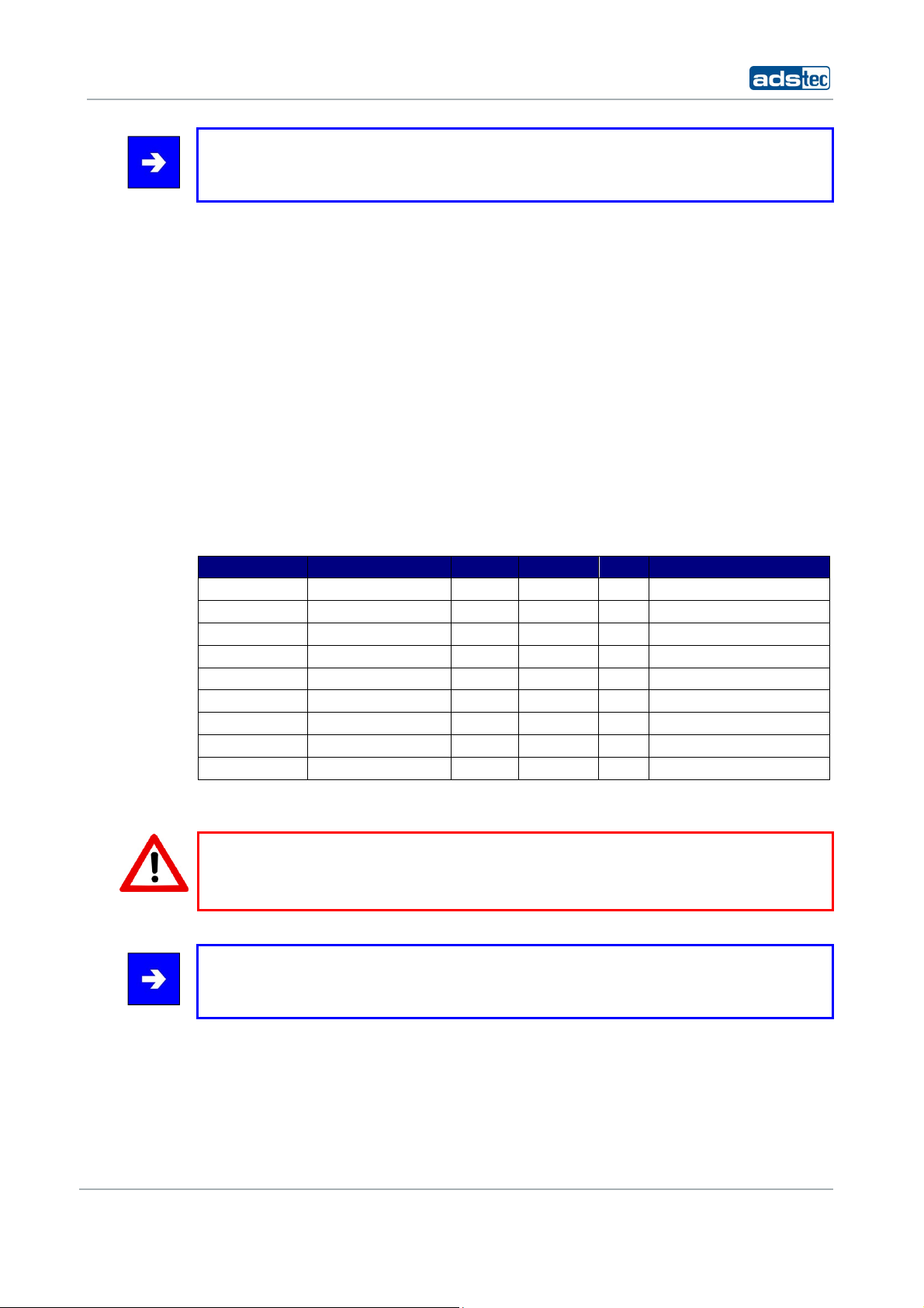
2.6 ANTENNA LIST FOR USE IN USA AND CANADA / FCC
• This antenna types can be used with the Access Points and Access Client in USA and
Canada. The antennas can be ordered at ads-tec GmbH. For the correct operation you
have to use an absorbability cabel for the different antenna types.
Ads-tec part number Ads-tec part descri ption Antenna type Frequency band Gain absorbability
DZ-PCKO-11032-0 RAP Antenne 2,4 GHz SMA-R 5dBi Swivel 2,4 ~ 2,4835 GHz 5 dBi none
DZ-PCKO-11033-0 RAP Antenne 5 GHz SMA-R 7dBi Swivel 5,1 ~ 5,835 GHz 7 dBi none
DZ-PCKO-11034-0 RAP Antenne 2,4 GHz N-fem. 9 dBi Omni 2,4 ~ 2,4835 GHz 9 dBi none
DZ-PCKO-11034-1 RAP Antenne 2,4 GHz N-fem. 12 dBi Omni 2,4 ~ 2,4835 GHz 12 dBi none
DZ-PCKO-11035-0 RAP Antenne 2,4 GHz N-fem. 12 dBi Panel 2,4 ~ 2,4835 GHz 12 dBi none
DZ-PCKO-11035-1 RAP Antenne 2,4 GHz N-fem. 18 dBi Panel 2,4 ~ 2,4835 GHz 18 dBi
DZ-PCKO-11036-0 RAP Antenne 5 GHz N-fem. 12 dBi Omni 5,1 ~ 5,835 GHz 12 dBi
DZ-PCKO-11037-0 RAP Antenne 5 GHz N-fem. 12 dBi Panel 5,1 ~ 5,835 GHz 12 dBi
DZ-PCKO-11037-1 RAP Antenne 5 GHz N-fem. 20 dBi Panel 5,1 ~ 5,835 GHz 20 dBi
*1 It has at 2,4GHz 22.5dB/100m absorbability and at 5GHz 35.9dB/100m absorbability. Additional every plug has 0.5dB absorbability.
minimum 20m
(it is a Ecoflex10*
minimum 14m
(it is a Ecoflex10*
minimum 20m
(it is a Ecoflex10*
minimum 37m
(it is a Ecoflex10*
1
cable to use)
1
cable to use)
1
cable to use)
1
cable to use)
Warning:
Behalf of the correct operation you have use an absorbability element for the different
antenna types.
Note:
Also light wave conductor cable can be used. It is necessary to use terminating
impedance for the correct use.
© ads-tec GmbH • Raiffeisenstr.14 • 70771 Leinfelden-Echterdingen
11
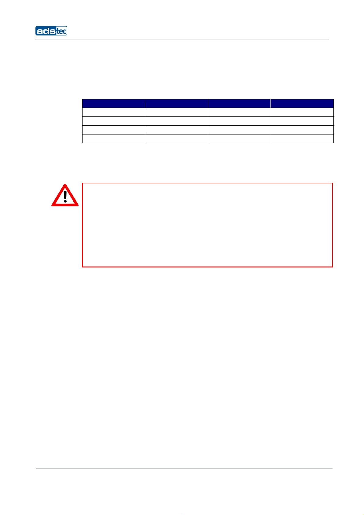
2.7 CHANNEL LIST FOR USE IN USA AND CANADA / FCC
• The following List showes the pool of available frequency and channles for the use in
USA and Canada. The customer can define between Indoor and Outdoor use. This
option can be selected by a checkbox in the web interface.
Frequency Channel Indoor use Outdoor use
2,4 GHz (2.400~2.483GHz) 1 – 11 X X
5 GHz (5.18~5.24GHz) 36,40,42,44,48 X
5 GHz (5.725~5.825GHz) 149 ,153,157,161,165 X
5 GHz (5.725~5.825GHz) 149 ,153,157,161,165 X
2.8 WLAN INSTRUCTIONS
Warning:
These warnings need to be observed during operation:
•
The unit does not provide a „secure“ transmission medium
•
The units cannot be used to establish a real-time system
•
The units’ system behaviour is non-deterministic
•
MIN/MAX roaming period is not guaranteed
Setting the applicable regulatory authority as well as the respective antenna amplification
is solely the responsibility of the operator.
IT Infrastructure RAP/RAC1000
12
© ads-tec GmbH • Raiffeisenstr.14 • 70771 Leinfelden-Echterdingen
IT Infrastructure RAP/RAC1000
3 INTRODUCTION
Reliable, stable and secure wireless LAN connections: employing state-of-the-art
technology, the industrial Rugged Access Point (RAP) provides
variety of applications, such as commissioning, mobile computing and data communication.
The RAP supports all applicable standards, including 802.11a/b/g, at a transmission
frequency of 2.4 and 5 GHz. Industrial applications necessitate sturdy technology. Whether
installed in a cold store or in great heat – thanks to its extended temperature range, the
RAP continues to function. Furthermore, the RAP is MIL-certified, which means it passed
one of the most demanding shock and vibration tests – this guarantees utmost
ruggedness.
Note:
In Case of Updates, it is possible that external Hyperlinks, which are used in this
Documentation, will not work properly or may be available under a different
Hyperlink.The Company ads-tec (also “ads-tec”) does not take over any kind of warranty
or adhesion for the functionality of Hyperlinks. Furthermore, ads tec does not take over
any kind of warranty or adhesion regarding the installation, use and the accuracy of all
open SOURCE software.
the
network interface for a
Note:
For the efficient online configuration of your ads tec devices, it is possible to download
the current version of the free Tool „IDA light “on the company`s homepage
http://www.ads-tec.de. The Tool offers you for example the possibility of defining
individual parameters or whole groups of parameters at a master device and to transfer
your settings to a limited selection and/or to all ads tec devices of same design and
version, without having to make these configurations time-consuming at each individual
device. You also have the possibility of assigning sequential IP addresses for your ads tec
devices.
With IDA light you can provide comfortably own groups of parameters according to your
specific requirements and modify them at any time.
Note:
This documentation always refers to both Access Point and Access Client, unless explicitly
stated otherwise.
© ads-tec GmbH • Raiffeisenstr.14 • 70771 Leinfelden-Echterdingen
13
A
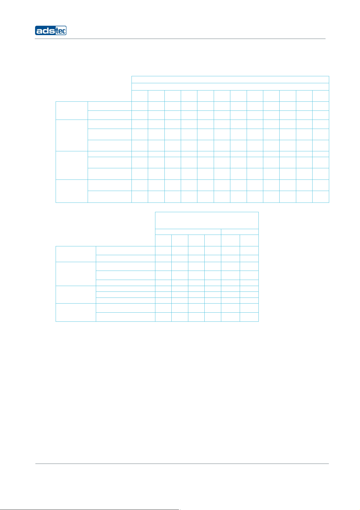
3.1 RAP AND RAC VERSIONS
Radio
modules
Ports
Power
supply
Client
mode
1 WLAN module x x x x
2 WLAN module s
1x Cu-RJ45 port x x x x
4x Cu-RJ45 port
(switch)
1x fibreoptic
Ethernet port
24 V DC x xxxxxxx x x xx
C integrated
110/230 V
Redundant energy
supply
RAP incl. client
mode
Seamless
Roaming Client*
IT Infrastructure RAP/RAC1000
RAP – Rugged Access Point
RAP1000 series
RAP
RAP
RAP
RAP
RAP
RAP
RAP
RAP
RAP
RAP
RAP
1110
1111
1210
1211
1120
1121
1220
1221
1510
1511
x x
x
x x
x x
x x x x x x x x x x x x
RAC – Rugged Access Client
x x x x
x
x x x
x
x x x x
x x x x
x x x x
x x
x
x x x x x
x
RAP
1520
1521
x x
x
x x
RAC1000 series RAC2000 series
RAC
RAC
Radio modules
Ports
Power supply
Client mode
1120
1 WLAN module x
2 WLAN modules x x x x x
1x Cu-RJ45 port x x x x
4x Cu-RJ45 port (switch)
1x fibreoptic Ethernet port x x
24 V DC x x x x x** x**
AC integrated 110/230 V x x
Redundant energy supply x x x
RAP incl. client mode
Seamless Roaming Client* x x x x x
1121
RAC
1220
1221
* Seamless Roaming Clients: From access point to access point without any packet loss or interruption of data
transmission
**12 – 24V
RAC
RAC
2110
RAC
2120
14
© ads-tec GmbH • Raiffeisenstr.14 • 70771 Leinfelden-Echterdingen

IT Infrastructure RAP/RAC1000
RJ45 (Registered Jack 45 = standardised jack) is an Ethernet standard frequently
used in telecommunication applications. Transmission method is equivalent to 10/100Mbits
half & full DUPLEX 100 BASE-TX.
Optical fibres are flexible optic media for controlled conduction of light. Contrarily to the
Ethernet standard, the fibre optic connection technology is insensitive to voltage
interference.
The plugs required for implementation are equivalent to the MTRJ Standard Multimode
with a 100Base-FX 100 Mbit⁄s Ethernet transmission via fibre optics.
© ads-tec GmbH • Raiffeisenstr.14 • 70771 Leinfelden-Echterdingen
15

IT Infrastructure RAP/RAC1000
3.2 SCOPE OF SUPPLY
Package contents need to be checked for integrity and completeness:
• 1 device
• 1 x two-pole COMBICON plugs (in case of 24V DC devices)
Manufacturer: Phoenix Contact
Item description/item short text: FMC 1,5 / 2-STF-3,5
• 1 x three-pole COMBICON plugs (in case of 230V AC devices)
Manufacturer: Phoenix Contact
Item description/item short text: MC 1,5 / 3-ST1F-5,08
• Four or eight antennas (depending on variant)
• Grommets / blanking plugs
• Installation kit with mounting plate and fasteners (fixed to device)
• Quick Install Guide / Quick Mount Guide
• GNU General Public License
• Service CD
3.3 ENVIRONMENTAL CONDITIONS
The unit can be put into operation and used under the following conditions. Failure to
observe any one of the specified data will immediately terminate all warranty conditions.
ads-tec cannot be held liable for any damages arising due to improper device or unit use
and handling.
• Permissible ambient temperature
during operation from -20 … 55° C
during storage from -20 … 55° C
• Humidity
during operation 10 to 85%, without condensate
during storage 10 to 85%, without condensate
• Vibration
during operation 1 G, 10 to 500 Hz
Vibration certificate: MIL-STD-810F 514.5 C-2
5 to 500 Hz (01-01-2000)
• Shock
during operation 5 g, with a 30 ms half-cycle
(DIN EN 60068-2-29)
(DIN EN 60068-2-6)
16
© ads-tec GmbH • Raiffeisenstr.14 • 70771 Leinfelden-Echterdingen
IT Infrastructure RAP/RAC1000
4 MOUNTING
4.1 MOUNTING CONDITIONS
The device is designed for industrial operations and may be employed wherever the
environment conditions specified above are met. In order to ensure optimal mounting and
operation, the unit should be placed at suitable location at which WLAN connectivity is not
impaired. WLAN connectivity is adversely influenced by iron beams and thick concrete
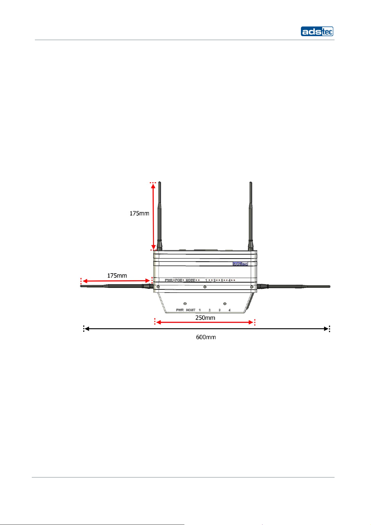
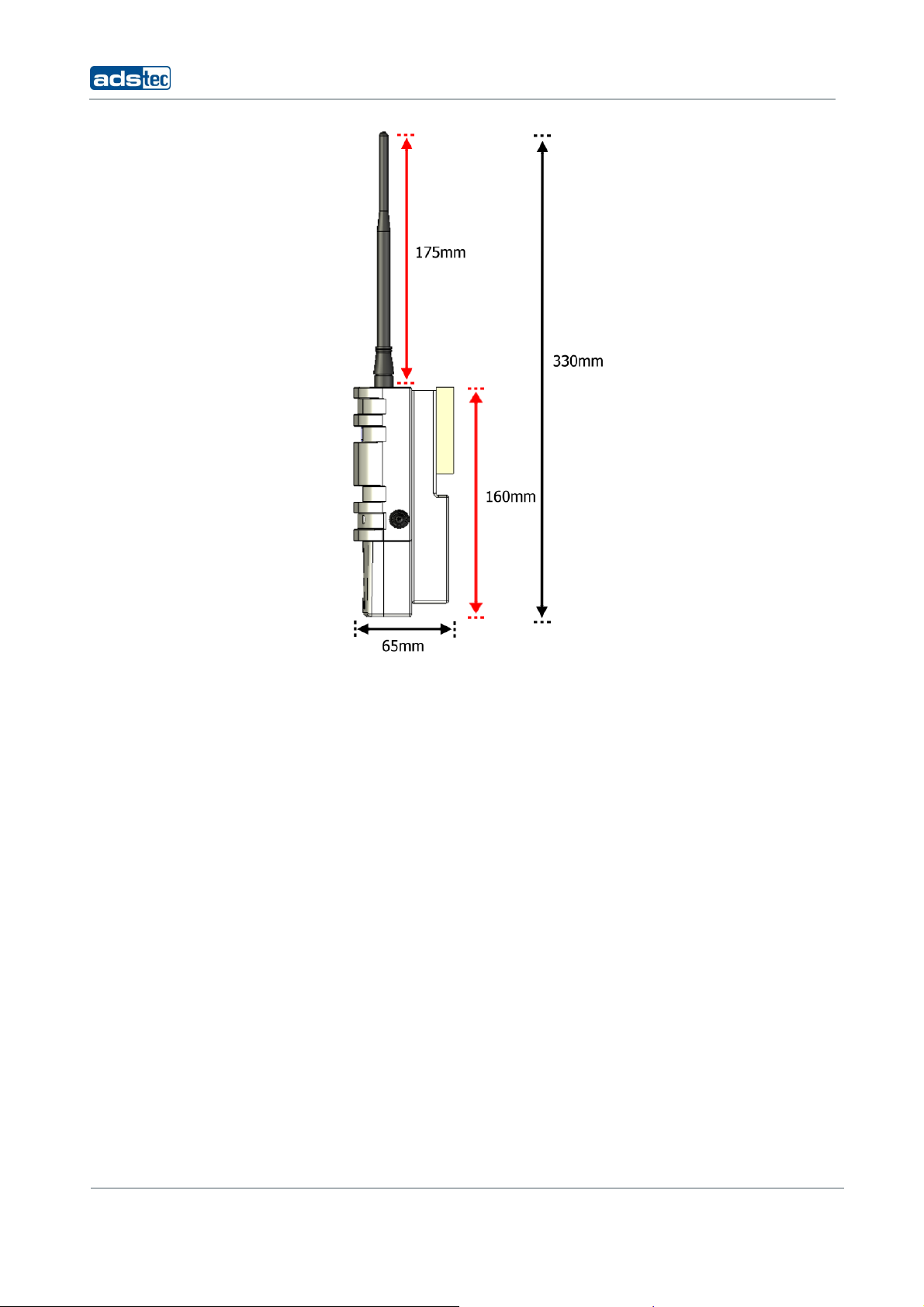
4.2 EXTERIOR DEVICE DIMENSIONS
walls.
Height: 160 mm (w/o antenna)
Width: 250 mm (w/o antenna)
Depth: 65 mm (w/o antenna)
© ads-tec GmbH • Raiffeisenstr.14 • 70771 Leinfelden-Echterdingen
17
IT Infrastructure RAP/RAC1000
18
© ads-tec GmbH • Raiffeisenstr.14 • 70771 Leinfelden-Echterdingen
IT Infrastructure RAP/RAC1000
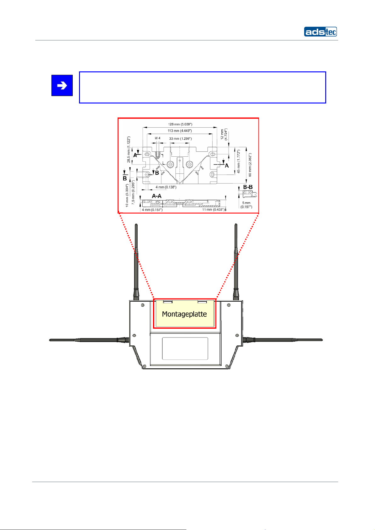
4.3 MOUNTING DIAGRAM
Note:
The mounting diagram shown herein is not 1:1 scale.
Please refer to the Quick Install Guide for a 1:1 scale diagram.
© ads-tec GmbH • Raiffeisenstr.14 • 70771 Leinfelden-Echterdingen
19
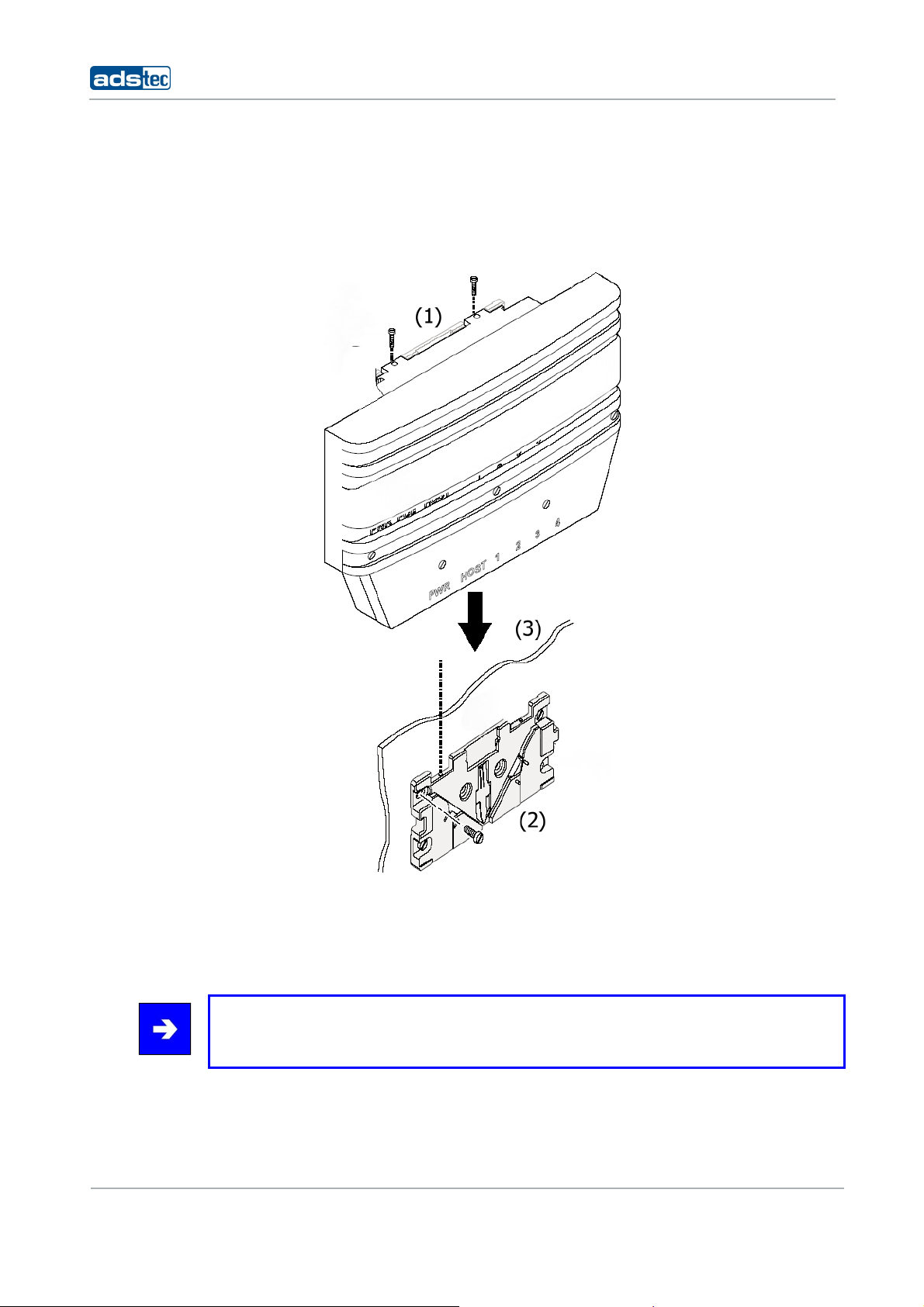
4.4 DEVICE MOUNTING
The mounting plate is pre-mounted to the device when delivered to the customer.
1) To install the device in the desired location, loosen the Allen screws (M4x12). (1)
2) Fix the mounting plate (w/o device) in the desired location. Ensure that the plate is held
by at least two opposing screws. (2)
IT Infrastructure RAP/RAC1000
3) Place the device onto the mounted fixture and make sure that device and fixture are
flush with each other. (3)
4) Secure the device inside the fixture using the previously removed Allen screws. (1)
Note:
Please ensure that the device is not mounted behind or next to another object as this
may impair the unit’s transmission performance and connectivity.
20
© ads-tec GmbH • Raiffeisenstr.14 • 70771 Leinfelden-Echterdingen
IT Infrastructure RAP/RAC1000
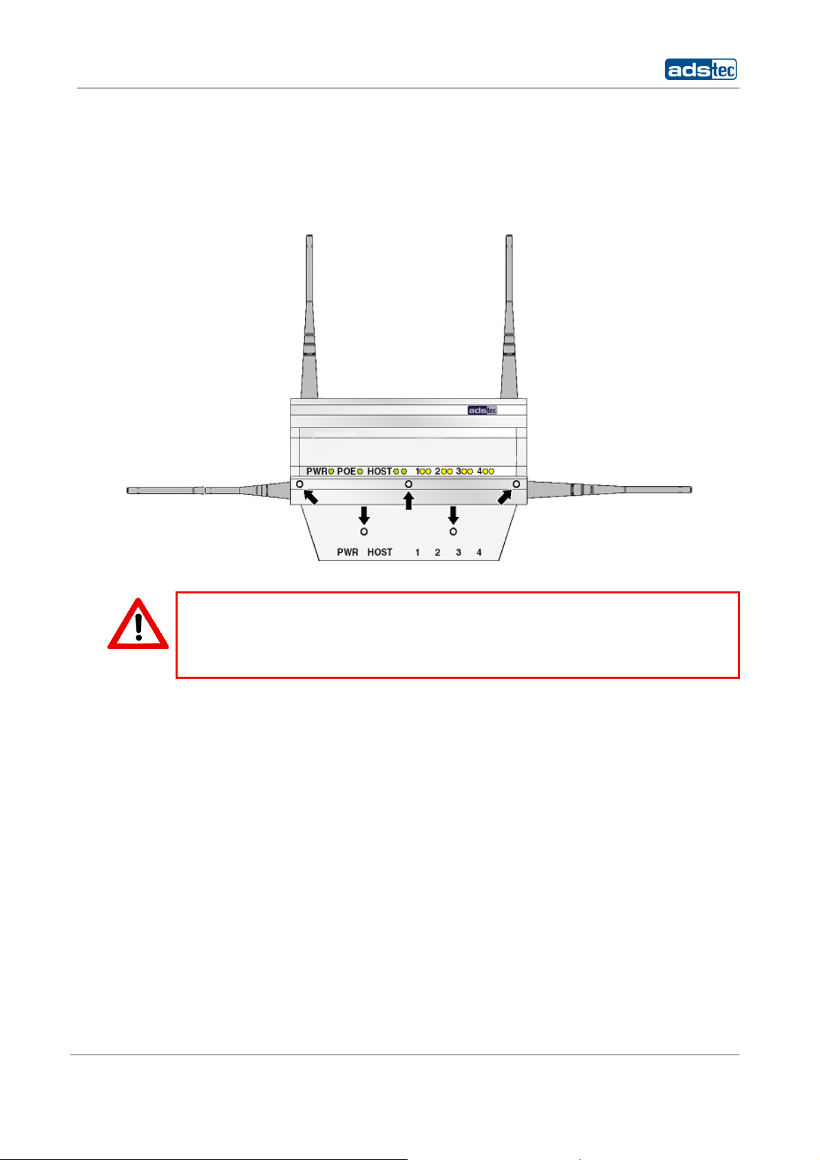
4.5 CONNECTING SUPPLY LINES
The supply connection, as well as device interfaces, is located inside the unit. The
maintenance duct cover needs to be removed before supply lines and interface cables can
be connected.
Please remove the five screws (M3x8) indicated below.
Warning:
To avoid damage to the unit’s electronics, switch off the device before establishing or
removing any plug connections.
Observe permissible device voltage.
Once the maintenance duct cover has been removed, the supply lines can be
connected to the device.
© ads-tec GmbH • Raiffeisenstr.14 • 70771 Leinfelden-Echterdingen
21
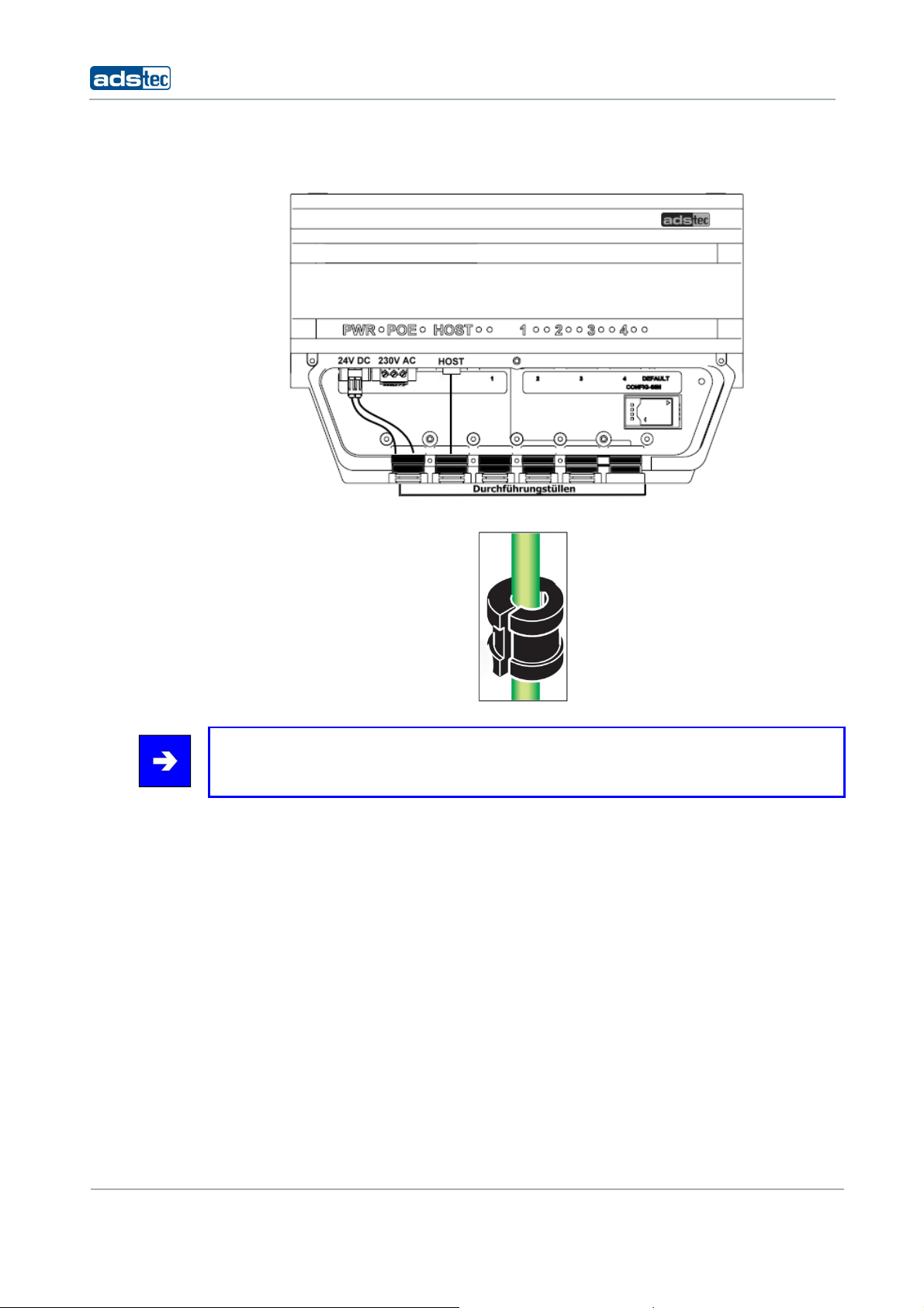
IT Infrastructure RAP/RAC1000
The diagram shows an exemplary device configuration with 24V DC power supply and
host line.
To ensure IP65 protection all supply lines need to be fitted with suitable grommets.
Note:
Grommet sizes need to be chosen in accordance with the respective cable diameters.
Once the grommets have been placed around the cables, they need to be placed into the
intended slots.
Finally, put the maintenance duct cover back onto the device and screw it down with the
five screws removed previously.
22
© ads-tec GmbH • Raiffeisenstr.14 • 70771 Leinfelden-Echterdingen
IT Infrastructure RAP/RAC1000
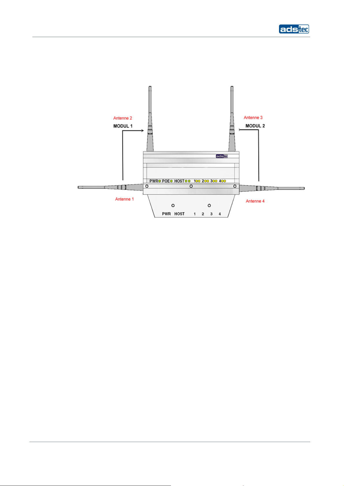
4.6 ANTENNA ASSEMBLY
For each WLAN module, 2 antennas should be installed.
Depending on the device variant, the unit accommodates up to two radio modules for two
separate WLANs. The full antenna assembly for each module consists of one vertical and
one horizontal antenna. The four or eight antennas supplied work at a frequency of
2.5GHz or 5Ghz (two or four each, respectively).
Screw the antennas onto the antenna connectors.
© ads-tec GmbH • Raiffeisenstr.14 • 70771 Leinfelden-Echterdingen
23
U
T
e
s
e
g
H
u
tec GmbH • Raiffeisenstr
s
t
n
e
g
IT Infrastr
cture RAP/RAC1000
5 S
5.1 LED
YSTEM FEAT
STATUS INDICA
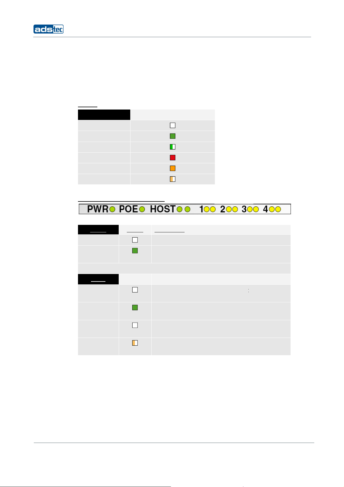
The device is fitt
facilitates an onexplains the differ
L
EGEND
LED status
off
green
green, flashing
ret
orange
orange, flashin
P
OWER SUPPLY /
RES
ORS
d with LEDs that indicate the status of the re
ite status diagnosis of the Access Point/Client.
nt states of the LED indicators:
Shown in table as
OST / S
WITCH
pective interfaces. This
The followin
overview
P
OWER
PWR
PWR
S
TATUS
D
ESCRIPTION
No power supply.
Device connected to power supply
use.
HOST
L
EFT
LED
Interface not connected to remote s
LINK
L
EFT
LED
LINK
R
IGHT
LED
ACT
Right LED
ACT
Interface connected to remote statio
use.
No data transfer between devic
station.
Indicates data transfer between dev
station.
and ready for
ation.
and ready for
and remote
ice and remote
24
© ads-
-Echterdingen
IT Infrastructure RAP/RAC1000
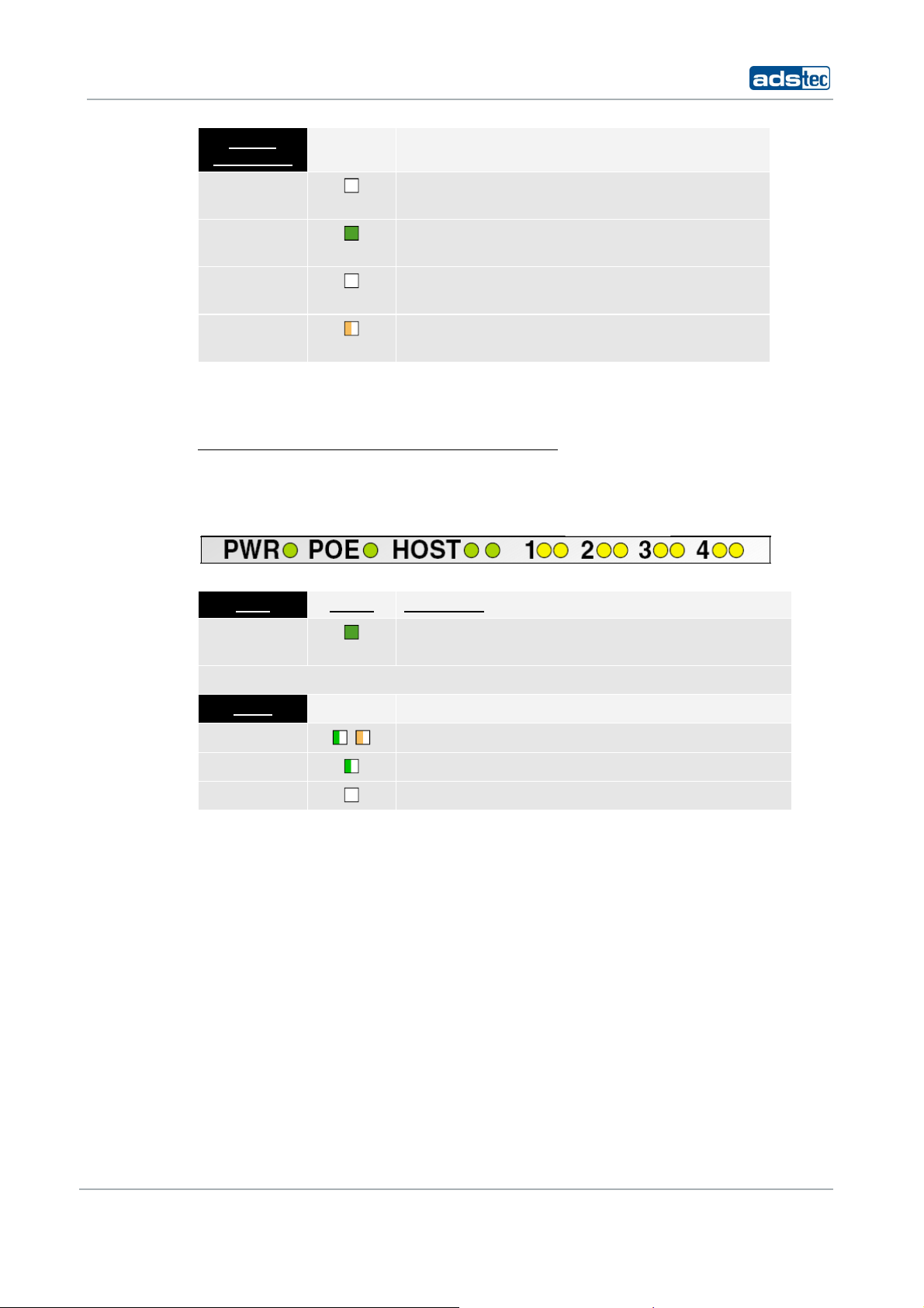
SWITCH
1 / 2 / 3 / 4
LEFT LED
Interface not connected to remote station.
LINK
LEFT LED
LINK
RIGHT LED
ACT
Right LED
ACT
Interface connected to remote station and ready for
use.
No data transfer between device and remote
station.
Indicates data transfer between device and remote
station.
5.2 LED STATUS INDICATORS DURING OPERATION
BEHAVIOUR OF STATUS INDICATORS DURING BOOT SEQUENCE
The boot sequence is initiated as soon as the Access Point / Client is connected to a power
supply. The HOST indicator LEDs can be used to monitor the boot sequence. Please refer
to the following overview to verify the device boots correctly. The overview assumes that
no cable is connected to HOST.
PWR STATUS DESCRIPTION
L+
Device is connected to power supply via POWER and
ready for use.
HOST
LINK / ACT
LEDS FLASH BRIEFLY ONCE
LED FLASHES SLOWLY, THEN QUICKLY (20X)
LED EXTINGUISHED
© ads-tec GmbH • Raiffeisenstr.14 • 70771 Leinfelden-Echterdingen
25
IT Infrastructure RAP/RAC1000
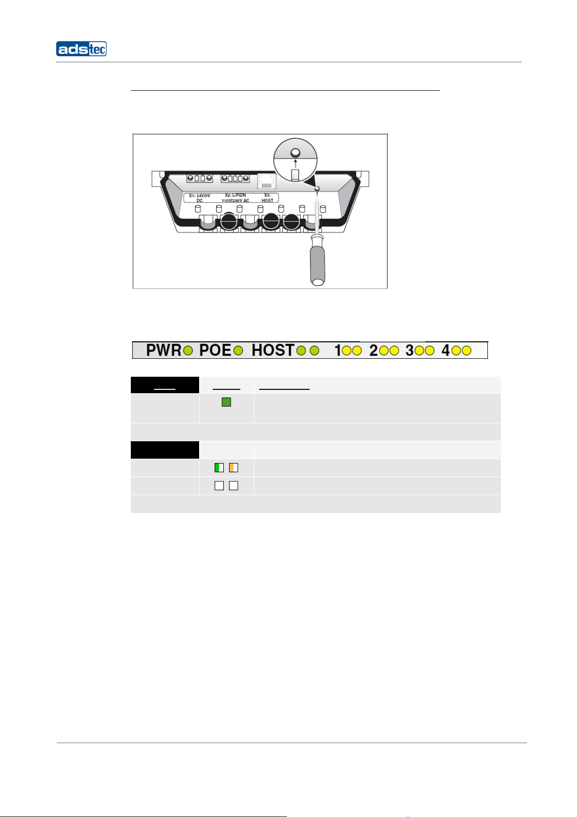
BEHAVIOUR OR STATUS INDICATORS DURING RESET TO DEFAULT SETTINGS
The reset button located under the interface cover may be used to reset the Access Point /
Client to factory default settings at any time and without regard to the current device
configuration.
To reset device to default settings, press reset button and switch on the device. Keep reset
button pressed for approx. 20 seconds. Button may be released as soon as left HOST
indicator LED turns green. The following overview assumes that no cable is connected to
HOST. Please refer to the overview to monitor the reset to factory defaults.
PWR STATUS DESCRIPTION
L+
Device is connected to power supply via POWER and
ready for use.
HOST
LINK / ACT
LINK / ACT
LEDS FLASH CONTINUOUSLY
LEDS EXTINGUISHED
26
© ads-tec GmbH • Raiffeisenstr.14 • 70771 Leinfelden-Echterdingen
IT Infrastructure RAP/RAC1000
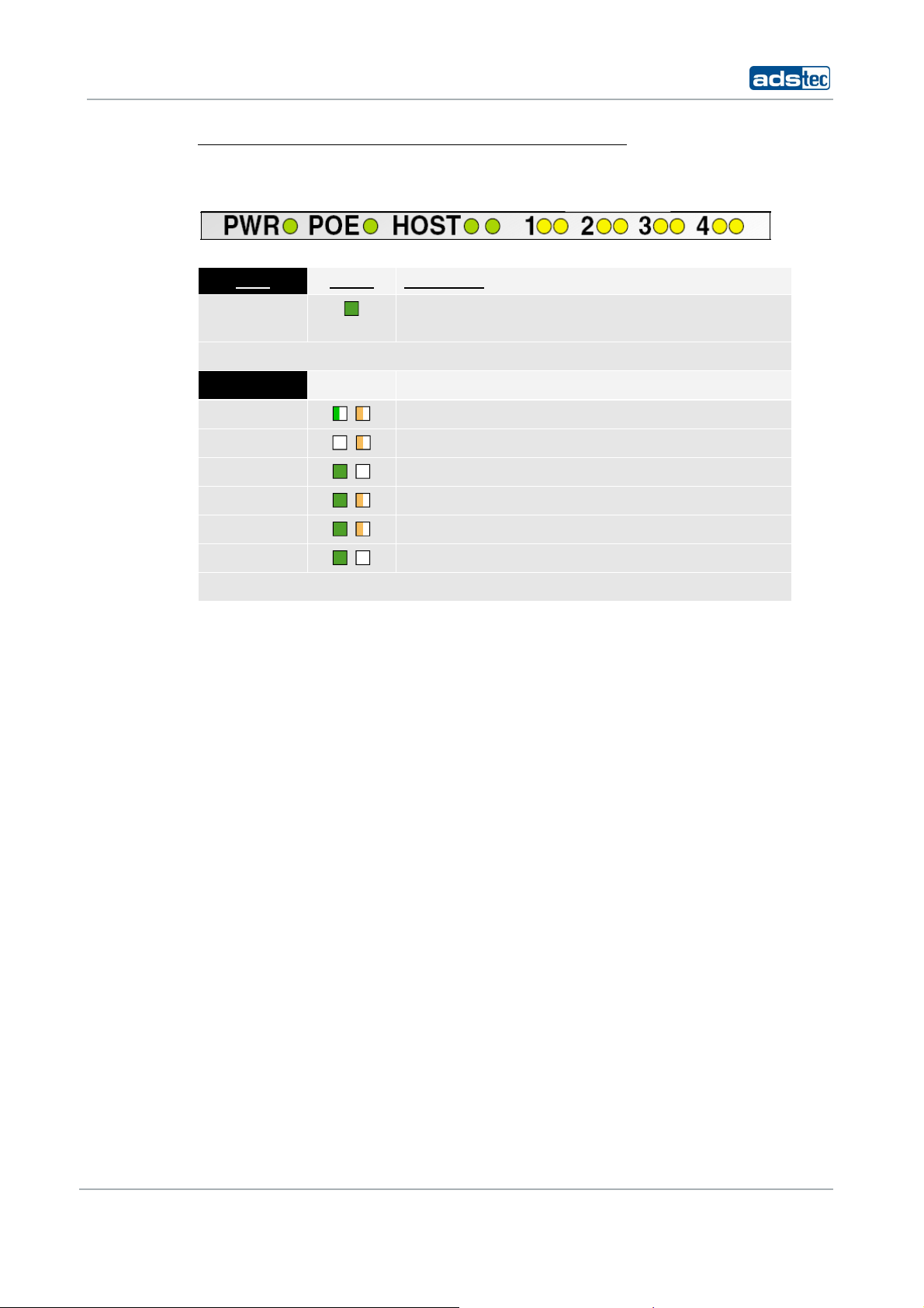
BEHAVIOUR OF STATUS INDICATORS DURING FIRMWARE UPDATE
The web interface can be used to perform firmware updates. Once initiated, the actual
update may take several minutes to complete. Please refer to the following overview to
monitor the firmware update sequence.
PWR STATUS DESCRIPTION
L+
Device is connected to power supply via POWER and
ready for use.
HOST
LINK / ACT
LINK / ACT
LINK / ACT
LINK / ACT
LINK / ACT
LINK / ACT
LEDS FLASH QUICKLY
LINK EXTINGUISHED / ACT FLASHES
LINK LIT UP / ACT EXTINGUISHED
LINK LIT UP / ACT FLASHES SLOWLY
LINK LIT UP / ACT FLASHES QUICKLY
LINK LIT UP / ACT EXTINGUISHED
THE WEB INTERFACE MAY SUBSEQUENTLY BE STARTED BY SELECTING “TRY TO RECONNECT”
© ads-tec GmbH • Raiffeisenstr.14 • 70771 Leinfelden-Echterdingen
27
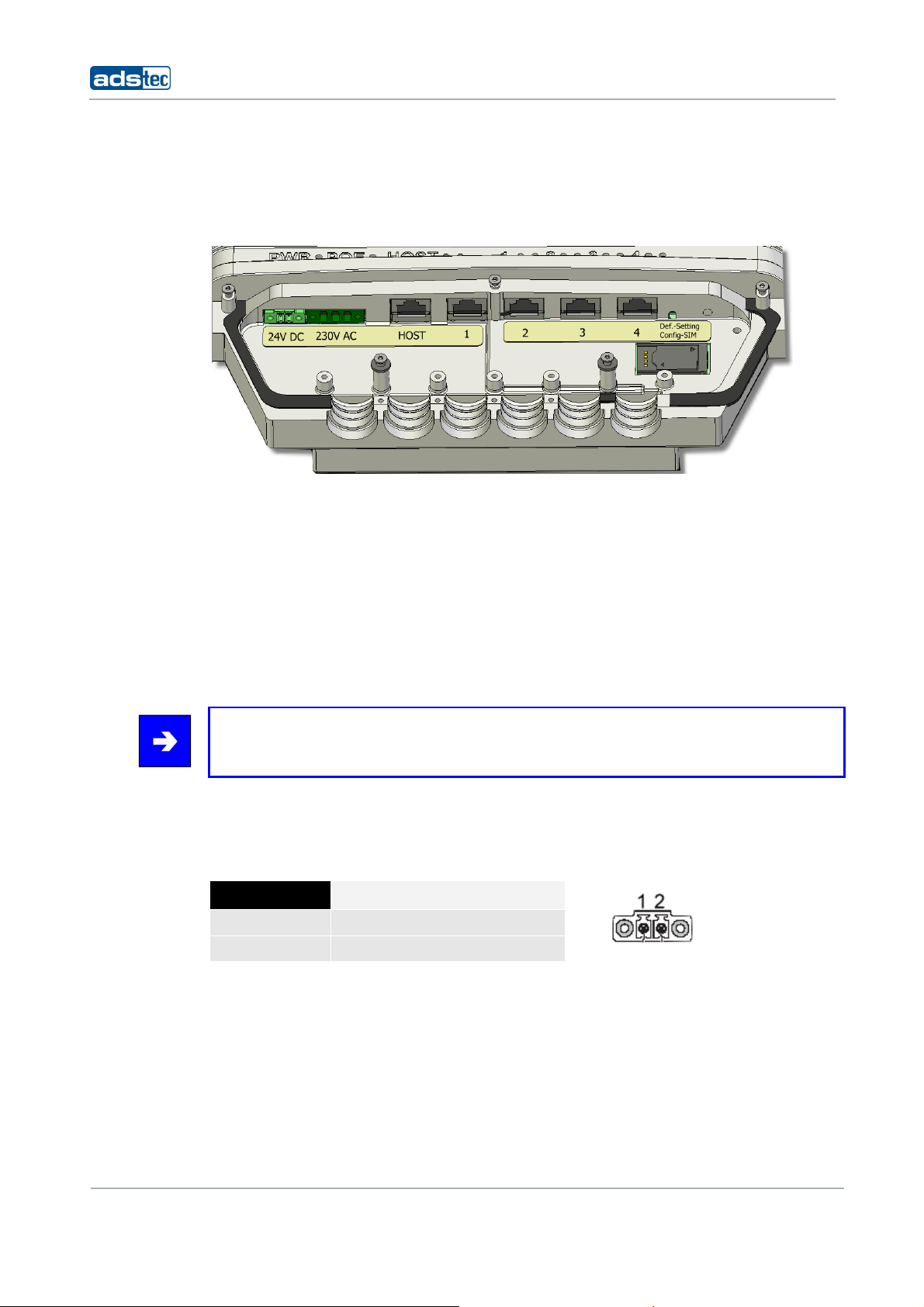
5.3 INTERFACE OVERVIEW
The following figure shows the available device interfaces. The exact interfaces may differ
depending on the device variant.
The device is equipped with the following interfaces:
1. Power 24V DC power supply (two-pole COMBICON plug)
2. Power 230V AC power supply (three-pole COMBICON plug)
3. HOST RJ45 or Optical connector
4. SWITCH 4x RJ45 connector (optional feature for Access Client)
5. Default reset button
6. SIM card reader
IT Infrastructure RAP/RAC1000
Note:
Input voltages may be connected redundantly (i.e. Power 24V DC, Power 230V AC).
5.3.1 POWER SUPPLY 24V DC
A bushing terminal with threaded connector is used to establish the power supply
connection (diagram shows bushing inside device).
PIN NUMBER SIGNAL NAME
1 24V DC
2 0V DC
PIN 1: = L+ 24V DC power supply
PIN 2: = GND Ground
28
© ads-tec GmbH • Raiffeisenstr.14 • 70771 Leinfelden-Echterdingen
IT Infrastructure RAP/RAC1000
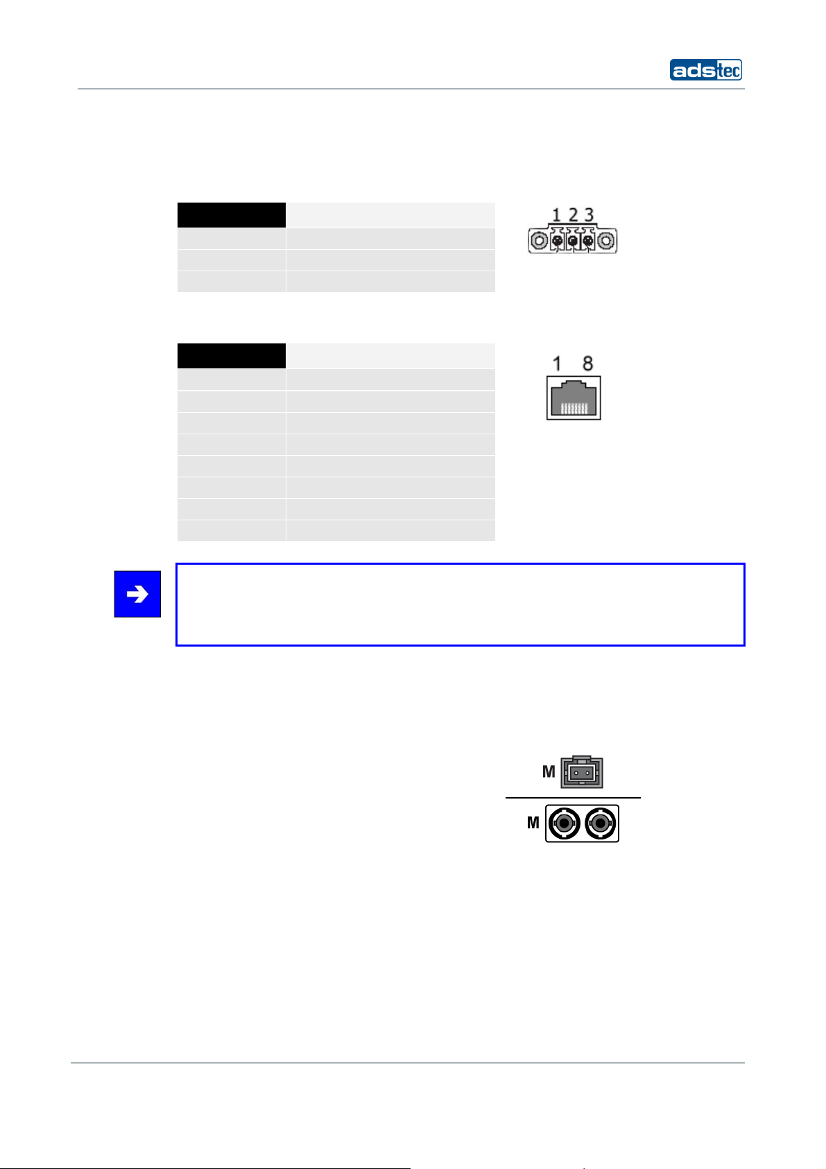
5.3.2 POWER SUPPLY 110/230 VAC
A bushing terminal with threaded connector is used to establish the power supply
connection (diagram shows bushing inside device).
PIN NUMBER SIGNAL NAME
1
2
3
110/230 V AC
PE
0 V DC
5.3.3 POWER SUPPLY HOST (IEEE 802.AF)
PIN NUMBER SIGNAL NAME
1
2
3
4
5
6
7
8
TX +
TX -
RX +
G
G
RX -
-48V
-48V
Note:
Transmission of 48V DC power supply is designed for a maximum feeding distance of 100
meters (approx. 330 ft.) in accordance with Ethernet specification requirements. The
connected devices may draw 350 mA of power; maximum supply power is 15.4 Watts.
5.3.4 F
IBRE OPTIC ETHERNET
The optical connection requires an MTRJ fibre optic connector.
Multimode cable, MTRJ connector to Duplex connector 62.5/125µm.
© ads-tec GmbH • Raiffeisenstr.14 • 70771 Leinfelden-Echterdingen
29
IT Infrastructure RAP/RAC1000
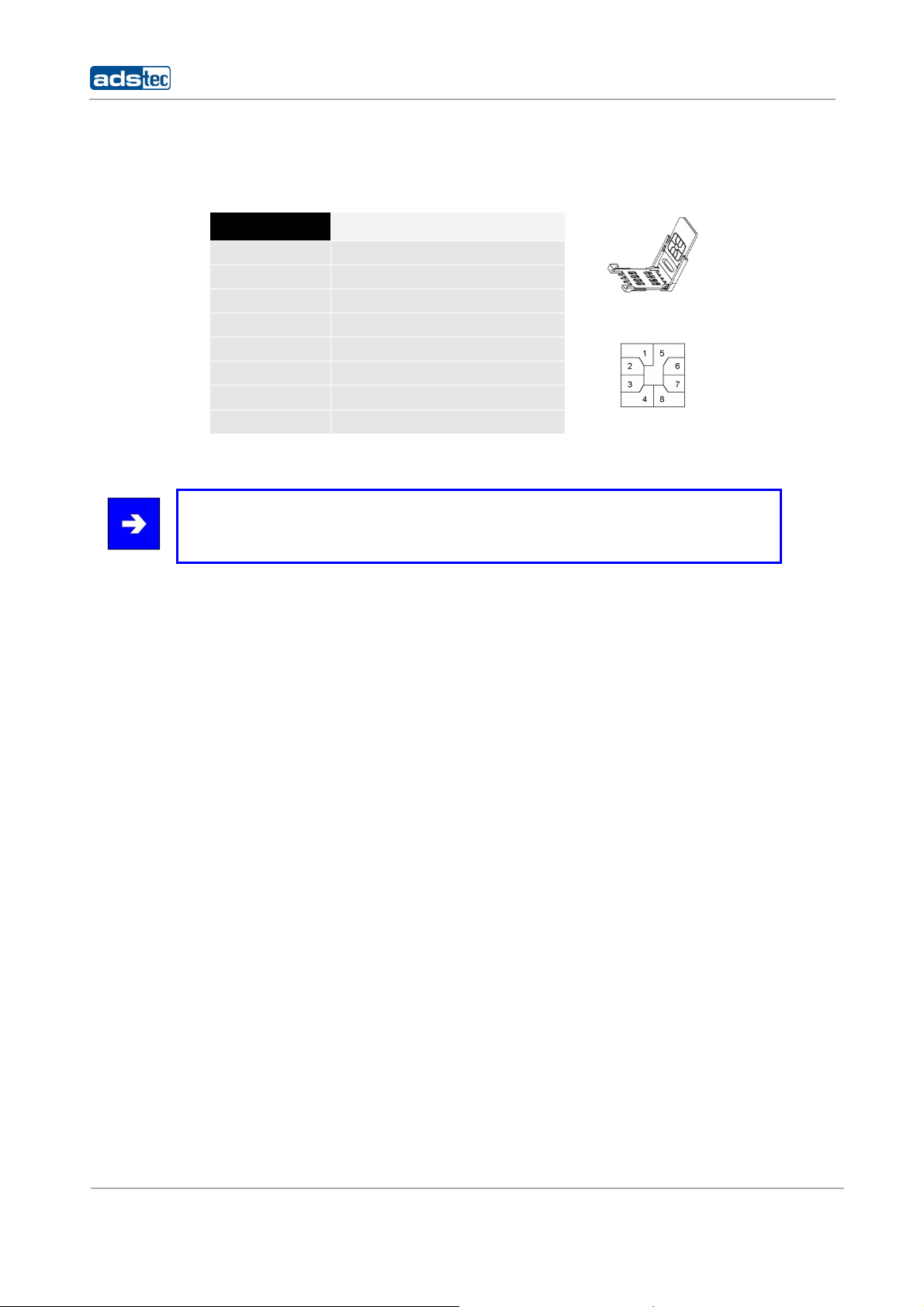
5.3.5 SIM CARD READER, ISO 7816-COMPATIBLE
The SIM card reader is used for saving configuration data.
PIN NUMBER SIGNAL NAME
1
2
3
4
5
6
7
8
VCC 5 Volt
RESET
CLOCK
n/c
GND
n/c
I/O
n/c
Note:
Interface and supply connectors are located on the bottom of the device. Secure
plugs against slipping out.
30
© ads-tec GmbH • Raiffeisenstr.14 • 70771 Leinfelden-Echterdingen
 Loading...