

ADS-TEC OPC7000 User Manual

y
Quick Start Guide OPC7000 series mounting/commissioning
Warning: Please observe installation guide
for OPC7022 enclosure!
1
110523_ QUICK START GUIDE OPC7000_EN_DZ-HAND-91044-1 V1.0
© ads-tec GmbH • Raiffeisenstr.14 • D-70771 Leinfelden-Echterdingen; German
y
1. Installation 3. Commissioning
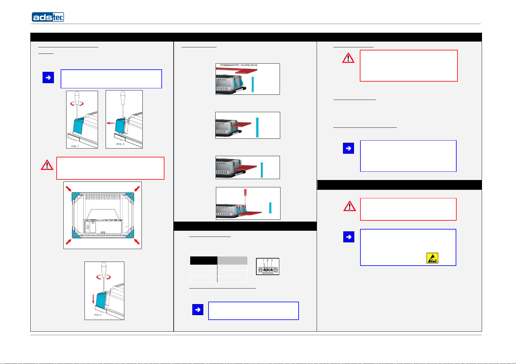
1.1 Fixing at the place of installation
OPC7008
Before the device can be integrated in the panel, the tensioner fixing screws
must be loosened until the tensioners open.
(Pos. 1 – pos. 2).
Note:
Tensioners can be opened by using a 3mm Allen key.
Now, position the device inside the installation recess.
Attention:
In order to position the device correctly, the opened
tensioners should be held back by hand while inserting the
device in the installation recess.
Fasten the tensioner screws until hand-tight once the device is installed in the
recess. (Pos. 3)
OPC7013/7015/7022
Cut the recess in the switch panel or switch cabinet door according to the
dimensions shown in the installation picture. The tensioner fixing screws must
be loosened. The screws can be loosened by using a TX8 screwdriver.
Then insert the device into the recess created in the described way. The
tensioners will snap back.
Please make sure to insert the device carefully into the switching cabinet. After
that, the tensioners will snap back to the front. Now the device is safely fixed in
the installation recess.
Tensioners must be fastened hand-tight.
2. Connection of supply cables
2.1) Power supply connection
The device is supplied with power by a 24V DC (3-pin) power plug. Connect the
device with a suitable power supply device.
24 V DC power supply
PIN NUMBER SIGNAL NAME
1 24V DC
2 PE
2.2) Connection of all required supply cables
A network connection is unconditionally required for the initial device
installation.
3 0V
Note:
An external keyboard must be connected allowing
you to enter any data into the device.
Quick Start Guide OPC7000 series mounting/commissioning
3.1) Switching the device on:
You can switch the device on by using the S1 Power button at the rear panel.
3.2) Entering the Product Key:
Please enter the Product Key once prompted to do so if you have a device with a preinstalled Windows operating system. You'll find the licence number on the rear plate of the
device.
3.3) PC LAN network adapter configuration
(Explained at the example of a Windows XP installation®)
The required network settings should be made by your network administrator.
4. Safety instructions
Warning:
The device may only be switched on after acclimatising
to the ambient temperature in order to avoid
condensate accumulation. The same applies if the
device has previously been exposed to extreme
temperature variations.
Note:
We would recommend you make use of the data on
our website at "www.ads-tec.de" in order to always
have up-to-date information, and to quickly get
comprehensive information about any technical
modification.
Warning:
Installation works at the device are only permitted if
the device is disconnected from the power supply and
protected from any accidental switch-on.
Note:
Always adhere to the safety measures applicable
when handling components at risk of being
destructed by electrostatic discharges.
(DIN EN61340-5-1 / DIN EN
61340-5-2).
2
110523_ QUICK START GUIDE OPC7000_EN_DZ-HAND-91044-1 V1.0
© ads-tec GmbH • Raiffeisenstr.14 • D-70771 Leinfelden-Echterdingen; German
 Loading...