

ADS Environmental Services QR 775027 A3 User Manual

ADS Intrinsically-Safe TRITON+™
Installation, Operation, and
Maintenance Manual
November 2014 QR 775027 A3
1300 Meridian Street, Suite 3000
Huntsville, Alabama 35801
(256) 430-3366
www.adsenv.com

ii ADS TRITON+ Manual
2014 ADS
LLC. All rights reserved.
ADS , ADS Environmental Services, IntelliServe,
TRITON+
, XBUS, XIO, and Qstart are either trademarks or
registered trademarks of ADS LLC.
Microsoft, Windows, and Excel are registered trademarks of
Microsoft Corporation.
Scotchkote is a trademark of 3M.
Teflon is a registered trademark of E.I. du Pont de Nemours and
Company.
Telit is a registered trademark of Telit Communications PLC.
All other brand and product names are trademarks or registered
trademarks of their respective holders.
Notice of Proprietary Information
The information contained herein represents the latest information
available at the time of publication. ADS LLC reserves the right to
make any changes or modifications to the content of this document,
without notice, to reflect the latest changes to the equipment. No
part of this document may be reproduced in any form without the
written consent of ADS LLC.

Table of Contents iii
Table of Contents
Chapter 1 Introduction…….. ..................... 1-1
Intrinsic Safety ............................................................... 1-2
TRITON+ System Certification .............................. 1-3
Installation and IS Considerations .......................... 1-5
Special Conditions for Safe Use ............................. 1-6
Other Conditions for Safe Use ................................ 1-7
Maintenance Restrictions ............................................... 1-8
Warnings, Certifications, Cellular Modem
Compliance, and Conformity ......................... 1-10
Changes or Modifications ..................................... 1-10
Control Drawing ................................................... 1-11
European ATEX Hazardous Area Compliance ..... 1-13
IECEx (International Electrotechnical
Commission Explosive) Hazardous Area
Compliance .................................................... 1-19
CSA Hazardous Area Compliance ........................ 1-21
Declaration of Conformity .................................... 1-24
Installation and Configuratio n ...................................... 1-26
Product Warranty ......................................................... 1-28
New Product Warranty .......................................... 1-28
Out-of-Warranty Product Repairs ......................... 1-28
Troubleshooting Fee ............................................. 1-29
Shipping ................................................................ 1-29
Service .................................................................. 1-30
Chapter 2 System Overview ..................... 2-1
TRITON+ Flow Monitor ................................................ 2-4
Communications ..................................................... 2-4
Processor Board ...................................................... 2-5
Connector Ports ....................................................... 2-7
SIM Card Enclosure ................................................ 2-8
Power .................................................................... 2-10
Sensors ......................................................................... 2-15
Peak Combo Sensor .............................................. 2-15
Ultrasonic Depth Sensor ....................................... 2-18
Surface Combo Sensor .......................................... 2-19

iv ADS TRITON+ Manual
I/O and Modbus Capability .......................................... 2-23
Analog Inputs and Outp uts.................................... 2-23
Digital Inp uts and Outp uts .................................... 2-24
Modbus ................................................................. 2-24
Chapter 3 Sensor Installation and
Investigating Site Characterist ic s ................................... 3-4
Flow Hydraulics ...................................................... 3-4
Pipe and Manhole Characteristics ........................... 3-5
Installing the Sensors in the Pipe ................................... 3-7
Standard Installation ............................................... 3-7
Special Installations .............................................. 3-38
Securing the Sensor Cables in the Pipe and Manhole .. 3-64
Connecting the Sensors and Sampler to the Monitor ... 3-67
Securing the Dryer Tub e to the Monitor ............... 3-69
Chapter 4 Communication…… ................. 4-1
Cellular-Based Wireless Communication ...................... 4-3
Installing the Antenna and SIM Card ............................. 4-5
Gathering Parts and Supplies .................................. 4-5
Installing the Wireless Antenn a .............................. 4-7
Installing the SIM Card ......................................... 4-11
Connecting the Antenna to the Monit or ................ 4-14
Connecting t o the Monitor in the Field ........................ 4-16
Connecting Directly to the Monitor ...................... 4-17
Connecting t o the Monitor through t he ExPAC .... 4-18
Connection.. ..................... 3-1
Chapter 5 External Power……. ................. 5-1
Installation ...................................................................... 5-2
DC Power Requirements and Consumption ............ 5-3
Mounting the XIO or XBU S ................................... 5-4
Mounting the Recommended Power Supply ........... 5-6
Mounting the ExPAC ............................................ 5-10
Wiring the AC Power Source to the
Recommended Power Supply ........................ 5-15
Wiring the Power Suppl y to the ExPAC ............... 5-18
Running the Ground Wires ................................... 5-22

Table of Contents v
Wiring the ExPAC/XBUS/XIO to the Monitor .... 5-29
Final Instructions .................................................. 5-36
Chapter 6 Configuration and Activation .. 6-1
Hardware and Software Compatibility .................... 6-2
Starting Qstart ......................................................... 6-2
Setting Up the Qstart Parameters ............................ 6-3
Configuring the Monitor Location ................................. 6-7
Create and Configure the Monitor Location ........... 6-7
Configure the Monitoring Point(s) ........................ 6-10
Assigning and Editing Devices ............................. 6-12
Activating the Monitor ................................................. 6-72
Setting Up the RTU to Retrieve the Current Data
through Modbus ............................................. 6-74
Designating the Data for Retrieval ........................ 6-74
Verifying the Modbus Output Data ....................... 6-74
Running Se nsor Diagnostics ........................................ 6-76
Performing Confirmations............................................ 6-79
Collecting Data from the Monitor ................................ 6-82
Upgrading the Monitor Firmware ................................ 6-85
Viewing Diagnostic and Data Logs.............................. 6-87
Chapter 7 Monitor Installation .................. 7-1
Mounting the Monitor on Manhole R ung ...................... 7-3
Mounting the Monitor to the Manhole Wall .................. 7-4
Mounting the Monitor to the Manhole Rim ................... 7-7
Chapter 8 Analog and Digital Inputs and
Outputs…….. .................... 8-1
Analog Inputs ................................................................. 8-3
Connecting a Third-Party Instrument to an
Analog Input on the XIO ................................. 8-3
Analog Outputs .............................................................. 8-8
Connecting a Third-Party Device to an Analog
Output on the XIO ........................................... 8-8
Digital Inputs ................................................................ 8-13
Connecting a Third-Party Device to a Digital
Input on the XIO ............................................ 8-13

vi ADS TRITON+ Manual
Digital Outputs ............................................................. 8-16
Connecting a Third-Party Device to a Digital
Output on the XIO ......................................... 8-16
Chapter 9 Modbus………….. ..................... 9-1
Establishing a Modbus Connectio n ................................ 9-2
Setting Up a Serial Connection ............................... 9-2
Setting Up a Wireless Connection .......................... 9-9
Configuring the Monitor for Modbus Applications ..... 9-10
Modbus Data Registers ................................................ 9-11
Register Addresse s for Entit y Data ....................... 9-11
Chapter 10 Maintenance and
Maintaini ng the System Components........................... 10-2
Gathering Replacement Parts and Supplies........... 10-2
Inspecting the Monitor .......................................... 10-3
Inspecting, Cleaning, and Handling the
Sensors ......................................................... 10-18
Replacing the SIM Card ...................................... 10-21
Replacing the Fuses in the Monitor..................... 10-25
Interpret ing the Diag nostic LED Codes on the
ExPAC ......................................................... 10-31
Troubleshooting ......................................................... 10-33
General Monitor Problems .................................. 10-34
Communication Problems ................................... 10-38
Ultrasonic Depth Subsystem ............................... 10-42
Upward Depth Subsystem ................................... 10-47
Peak Velocity Subsystem .................................... 10-50
Surface Velocity Subsystem ............................... 10-53
Pressure Depth Subsyst em .................................. 10-55
Temperature Subsystem ...................................... 10-56
External Power, I/O, and Modbus S ubsystems ... 10-57
Troubleshooting ............ 10-1
Appendix A Specifications… .................... A-1
TRITON+ Flow Monitor ............................................... A-1
Intrinsically-Safe Sensors .............................................. A-5
USB Serial Interface ................................................... A-10

Table of Contents vii
ExPAC ........................................................................ A-11
Power Supply .............................................................. A-12
XBUS .......................................................................... A-13
XIO ............................................................................. A-14
Appendix B Part Numbers……. ................ B-1
Appendix C Monitor Activity Codes ......... C-1
Appendix D System Configuration and
Setup to Support the
Telog Ru-33……. .............. D-1
Configuring the Monitor to Support the Ru-33 ............. D-2
Connecting the Monitor to the Ru-33 ............................ D-2

C H A P T E R 1
Introduction
The ADS Intrinsically-Safe TRITON+™ flow monitor measures
open channel flow in sanitary sewers, storm sewers, combined
sewers, and other environments to assist municipalities and other
industry in addressing the following issues:
Planning sewer systems (sizing and rehabilitation)
Reducing infiltration and inflow (I/I)
Monitoring combined sewer overflows (CSOs)
Detecting and monitoring surchar ges
1-1
Managing inter-agency billing
Monitoring sewage handling facilities (wastewater treatment
plants and pump stations)
The battery- or externally-powered TRITON+ monitor provides
exceptional accuracy and reliability in measuring open-channel flow
depth and velocity to determine flow rate (quantity) in pipes. This
flow data is the essential element required to successfully p er form
investigative, analytical, and reporting activities.
This manual offers detailed instructions on installing, operating,
maintaining, and tr oubleshooting the TRITON+ flow monitor,
sensors, and communication hardware.

1-2 ADS TRITON+ Manual
United States
Germany
Poland
Australia
Hungary
Romania
Canada
Italy
Singapore
China
Japan
Slovenia
Croatia
Korea
South Africa
Finland
New Zealand
Turkey
France
Norway
United Kingdom
Intrinsic Safety
Intrinsic safety is an electronic hardware pr o tection concept that
ensures there a re no conditions under which the equipment can
operate that could cause a release of energy sufficient to ignite a
hazardous gas or dust mixture. Devices that meet the low power,
current-limited design criteria are deemed Intrinsically Safe (IS).
Special design, testing, quality, and inspection rules apply to
manufacturers and users of IS equipment due to the critical nature
of its deployment in hazardous areas. Areas where hazardous
conditions can be expected to be present on a constant basis are
classified (rated) as Zone 0 (equivalent to Class I, Division 1, in
North America).
The TRITON+ flow monitor (Model 8000-FST-IM) is certified for
use in North America in areas where the Class/Division system is
observed. The TRITON+ has been tested to worldwide IECEx
(International Electrotechnical Commission Explosive) standards
and is certified for use in areas requiring Class I, Division 1,
equipment. The IECEx scheme allows demonstrated compliance
for use in Zone 0 (equivalent to Class I, Division 1, in North
America) areas in the following countries:
Brazil India Russia
Czech Republic Malaysia Sweden
Denmark Netherlands Switzerland

The TRITON+ has also been certified for use in Zone 0 via testing
to ATE X (Atmosphere Explosibles) standards. It is certified to
ATEX standards in Europe and for use in all classified (hazardous)
sanitary sewer and industrial hazardous areas. Many rest-of-world
countries accept ATEX certification in lieu of their country-specific
requirements.
The TRITON+ flow monitor has been tested to CSA (Canadian
Standards Association) standards and certified for use in Canada in
Intrinsically Safe and Non-Incendive Systems – For Hazardous
Locations. The CSA certification allows demonstrated compliance
for use in Ex ia IIB T3 (152 C) areas in Canada.
It is the customer’s responsibility to ensure that the certification(s)
provided for the ADS equipment meets the applicable regulatory
requirements.
Note: TRITON+ models include the 8000-FST-IM and
8000-FST-IM-EP.
TRITON+ System Certification
Introduction 1-3
The TRITON+ unit and associated telemetry equipment are
certified for use only with approved ADS battery packs, sensors,
communication cables, and telemetry equipment. Connection of
any non-approved devices could result in unsafe operation and will
immediately void the warranty and IS certification.
Note: Connecting the Telog® Ru-33 to the ADS
TRITON+ is an approved application and, therefore, will
not void the TRITON+ warranty. However, because the
Telog unit is not IS certified, the installation will not be
considered intrinsically safe if the Ru-33 is installed in the
manhole with the monitor.

1-4 ADS TRITON+ Manual
Sensors
The TRITON+ monitor supports several approved IS sensors that
vary in measurement methodology, redundancy, and other features.
The monitor is approved for accommodating up to two of the same
or different types of IS sensors. Following are the approved IS
sensors:
Peak Combo Sensor Performs upward ultrasonic depth,
pressure depth, and peak velocity measurement and mounts at
or near the bottom of the pipe under the flow surface (ADS p/n
8K-CS4-05-35, 8K-CS4-15-35, or 8K-CS4-30-1H).
Surface Combo Sensor Performs downward ultrasonic
depth, surcharge pressure depth, surcharge peak velocity, and
surface velocity measurement and mounts at the top (or crown)
of the pipe above the flow (ADS p/n 8K-CS5-V2-05-30, 8KCS5-V2-15-30, or 8K-CS5-V2-30-1H).
Ultrasonic Depth Sen sor Performs downward ultrasonic
depth measurement alone and mounts at the top (or crown) of
the pipe above the flow (ADS p/n 8K-CS5-D1-00-30).
Extension cables are available for these sensors in lengths up to a
maximum of 300 feet (91 m). .
Note: Detailed descriptions and specifications for the
sensors are available in Chapter 2, System Overview, and
Appendix A, Specifications
Power
The TRITON+ flow monitor is powered by an internal 12-volt IS
battery pack (ADS p/n 8000-0043) or an external DC power source
through an external power and communications unit (ExPAC, ADS
p/n 8000-0377), external Modbus interface unit (XBUS
9000-0427), or an external i nput/output device (XIO
8000-0400).
Note: Using a battery pack that is not supplied by ADS
will void the warranty and IS certification of the monitor.
™
™
, ADS p/n
, ADS p/n

Introduction 1-5
Telemetry
Wireless communication is available to the TRITON+ monitor
through an antenna and internal UMTS/HSPA+/GSM modem. The
antenna through which wireless communication occ urs may be
located either inside or outside the manhole; however, ADS
recommends installi ng the antenna outside the manhole to maximize
signal strength.
Many antennas are available to mitigate signal strength issues.
While ADS offers two proven antenna options, customers also may
obtain their own antennas to accommodate specific project needs or
requirements. However, when assessing a third-party antenna,
please consult an ADS or IETG, as applicable, representative prior
to installing the antenna to verify the antenna can adequately
support monitor communications.
Connecting the TRITON+ to the Telog RTU (Model Ru-33) also
supports wirel ess communication via the Telog “passthrough”
mode. The Telog is mounted next to the TRITON+ in the
hazardous area and connected to the monitor using the Triton-Telog
Comm Cable (ADS p/n 8000-0054-01). However, please note that,
because the Telog unit does not possess IS certification, the
installation will not be considered intrinsically safe if the Telog unit
is installed in the manhole with the monitor.
Installati on a nd IS Considerations
When installing the TRITON+ flow monitor, carefully follow any
local regulations for the installation of IS equipment. For example,
many clients only allow the use of special hazardous area tools
(flashlights, radios, etc.) in manholes. Some clients will not allow
the use of an electric drill, either battery-powered or AC-powered,
in a manhole. In this case, air (i.e., pneumatic) tools must be used.
When in doubt as to the applicable regulations, check with the client
or the client’s designated safety representative.

1-6 ADS TRITON+ Manual
Special Conditi ons f or Safe Use
During the ATEX /IECEx/CSA approval process, certain conditions
are set fort h t hat must be observed when using the certified
equipment. These Special Conditions for Safe Use can be found in
the body of each certification (referenced in this manual), as well as
on a page attached to the Declaration of Conformity. Following is a
summary of these Safe Use Instructions:
Parts of the enclosure may be non-conducting and may generate
an ignition-capable level of electrostatic charge under certain
extreme conditions. Therefore, do not install this equipment in
a location where it may b e subject to external conditions (such
as high-pressure steam or dust) that may cause a buildup of
electrostatic charge on non-conducting surfaces.
As aluminum is used at the accessible surface of this unit, in the
event of rare incidents, ignition sources due to impact and
friction sparks may occur. This shall be considered when it is
being installed, particularly in locations that require equipment
with a Group II Ga level of protection.
The equipment (ADS Model 8000-FST-IM) shall be used in
the hazardous area only when fully assembled. Do not perform
any maintenance of internal parts, replacement of battery packs,
or replacement of fuses unless the unit is located in a safe area.
Applicable to the USB Serial Interface : Measures shall be
taken to limit transient over voltages to the USB Serial
Interface to an appropriately low level in accordance with
Overvoltage Category 1 (IEC 60664-1).
The equipment shall be installed as per installation drawing
8000BK0009.
The External Power and Communications Unit (ExPAC) may
only be mounted in a non-hazardous location.
The IS Modem DAA is only permitted to be connected to a
“Public Switched Telephone Netwo rk”.

The 8000-FHK/FST-IM Monitor Assembly common line is
connected to the metal enclosure. Therefore, when it is
powered by the “External Power and Communications Unit”
(ExPAC), the Monitor Assembly shall be bonded to the ExPAC
earth with a conductor having a minimum cross-sectional area
of 4 mm
2
, to achieve a resistance ≤1 Ω.
Other Conditions f or Sa fe Use
The ADS Model 8000-FST-IM shall use only the 12-volt IS
Battery Pack (ADS p/n 8000-0043) for internal power.
Only ADS-approved sensors shall be connected to the ADS
Model 8000-FST-IM: ADS sensor types 8K-CS4 and 8K-CS5.
The only communication devices that may be connected to the
COMM + EXT PWR connector on the TRITON+ are the
USB Serial Interface (ADS p/n 8000-0337), the
ExPAC/XBUS/XIO power cable (ADS p/n 8000-378-10/25),
the Direct Connect Interface (ADS p/n 8000-0054), and the
Sampler Cable (ADS p/n 8000-0348).
Introduction 1-7
Note: The Triton-Telog Comm Cable (ADS p/n 8000-
0054-01) also may be connected to the COMM + EXT
PWR connector on the TRITON+ to provide
communication between the Telog Ru-33 and the monitor.
However, because the Ru-33 is not certified for IS
operation, an installation involving a connection between
these units will not be considered intrinsically safe, unless
the Telog unit is installed outside the hazardous area.

1-8 ADS TRITON+ Manual
Maintenance Restrictions
As mentioned earlier, all ADS TRITON+ flow monitors are
manufactured to meet IS standards. The monitor’s IS certification
can be voided instantly if proper maintenance and service
procedures are not followed. ADS must restrict certain
maintenance tasks to ADS IS-certified technicians.
ADS-certified technicians carefully inspect and document their
repairs of IS monitors. This inspection and documentation process
provides legal protection should the monitor's performance or safety
be in question.
If you experience trouble with this equipment, please refer to this
manual for troub l eshooting guidel ines. The following maintenance
procedures may be performed in the field, but they must be
performed as described in this manual:
Installing and swapping monitor
Installing and swapping sensors
Installing and swapping battery pack
Swapping fuses in power regulator in monitor
Installing and swapping SIM card on monitor port
Replacing pressure depth sensor dryer tube and desiccant beads
Installing and swapping ExPAC (applicable only when not
housed within an XBUS or XIO), XBUS, or XIO
Cleaning sensors
Confirming sensors
Note: Please note that, in all applications, only ADS IScertified Service Technicians are authorized to perform
component-level service on the TRITON+.
If you have any questions about the procedures, warranty
information, or level of service you are allowed to perform on a

Introduction 1-9
monitor, please contact ADS (or IETG, when applicable) through
the contact information listed at the end of this chapter.

1-10 ADS TRITON+ Manual
Warnings, Certifications, Cellular Modem Compliance, and Conf ormity
Manhole and sewer system work involves confined space entry and
is inherently dangerous. Therefore, installers and technicians
should comply with all federal, state, and municipal regulations
concerning confined space entry.
In addition, personnel installing and maintaining this equipment
should follow all gui delines presented in this manual concerning
monitor installation and maintenance. Failure to strictly adhere to
these guidelines can result in personal injury and/or damage to the
monitor.
Changes or Modifications
Changes or modifications to the TRITON+ flow monitor not
expressly approved by the party responsible for compliance will
void the IS certification.
Personnel performing installation of the TRITON+ flow monitor
should carefully follow the guidelines contained in this manual
when installing and maintaini ng the monitor. Failure to str ic tly
adhere to these guidelines can result in personal injury and can
cause damage to the monitor, which would invalidate its warranty.
The TRITON+ flow monitor is designed to be installed in combined
and sanitary sewer lines and manholes. This installation work is
inherently danger ous. All applicable safety guidelines should be
followed and carried out by at least two fully trained and qualified
persons.

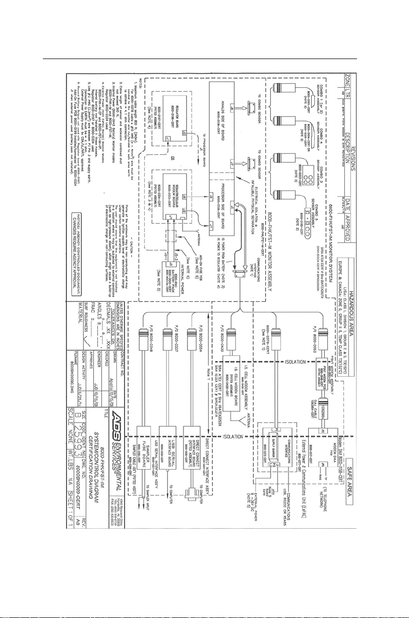
Control Drawing
This drawing depicts the interconnections allowed for the
TRITON+. It is intended for use by inspection professionals for
audit certificate compliance; however, it is a good tool for
understanding t he structure of the TRITON+ flow monitoring
system.
Introduction 1-11
1-12 ADS TRITON+ Manual
Control Drawing

Introduction 1-13
Note: This is an excerpt from an agency-controlled
document for ill ustration purposes only. Changes t o the
base controlled document require agency approval. For a
full-size copy of this drawing, please contact ADS and
request dra wing number 8000BK0009-CERT.
Note: The Telog R u-33 can be connected to the COMM
+ EXT PWR port on the TRITON+ monitor using the
Telog-Triton Comm Cable (ADS p/n 8000-0054-01).
However, this co nfi guration has not been included on this
drawing because the Telog unit is not certified for IS
operation. Therefore, a n installation involving this
configuration will not be considered intrinsically safe,
unless the Ru-33 is installed outside the hazardous area.
Cellular Modem Information and Compliance
Wireless telemetry is provided via a third-pa rty, F CC- and carrierapproved, commercial HSPA+/GSM or CDMA/EV-DO modem
inside the TRITON+ monitor and a corresponding antenna. Two
antenna options are available through ADS. However, customers
may obtain their own antennas to accommodate specific needs or
requirements. If a customer-supplied antenna is preferable or
required, consult an ADS or IETG, as applicable, representative
prior to installing the antenna to ensure it will adequately support
TRITON+ monitor communications and compliance.
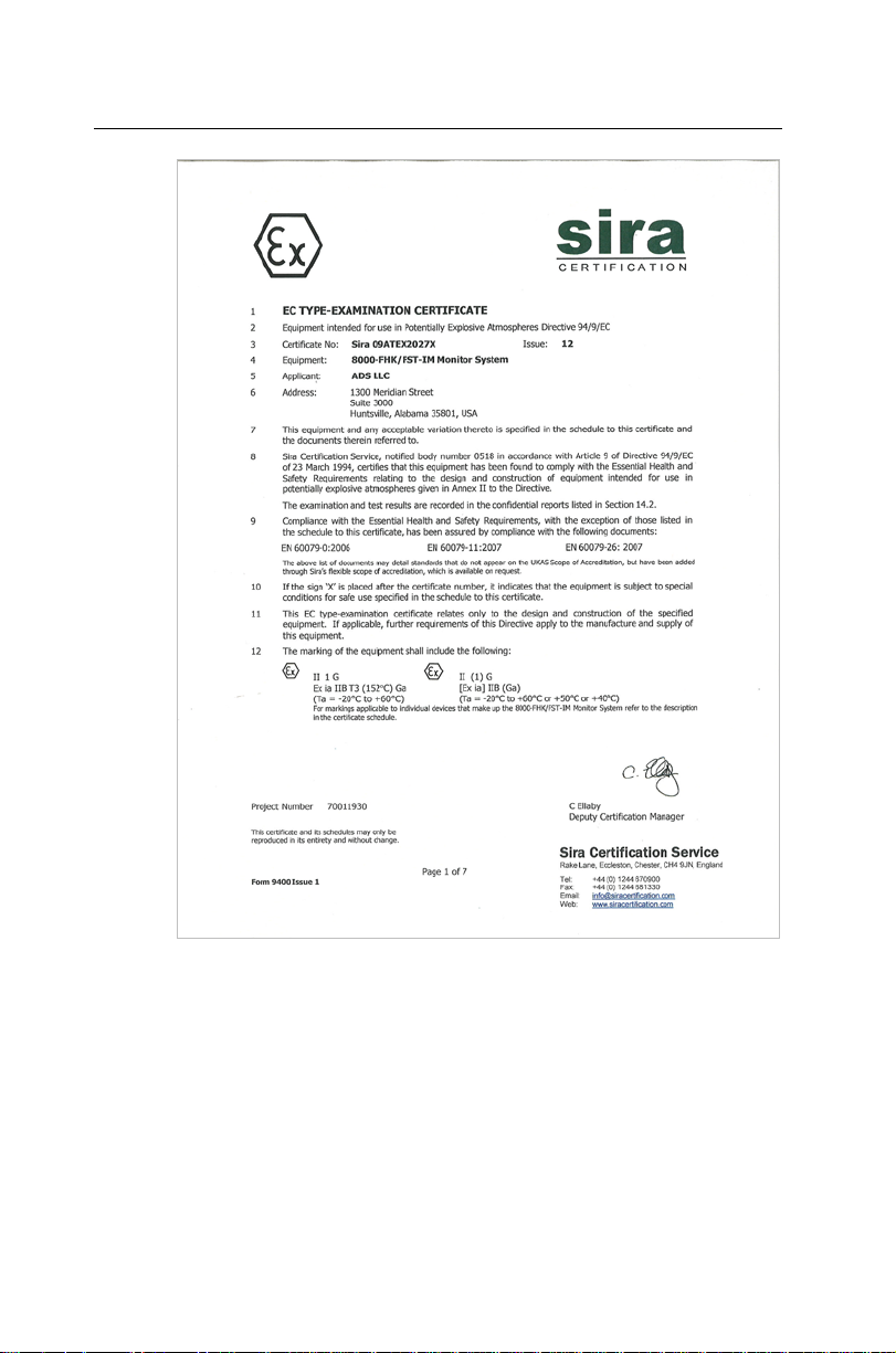
European ATEX Hazardous Area Compliance
The following instructions apply to equipment covered by the
certificate numbered Sira 09ATEX2027X (TRITON+, USB Serial
Interface, and Combo Sensors CSX Series). Reference European
ATEX Directive 94/9/EC, Annex II, 1.0.6:
The equipment may be used with flammable gases and vapors
with apparatus groups IIA and IIB and with temperature classes
T3 (152
o
C), T4, T5, and T6.

1-14 ADS TRITON+ Manual
The equipment is only certified for use in ambient temperatures
in the range of -20
o
C to +60oC and should not be used outside
this range.
The certificate number has an ‘X’ suffix, which indicates that
special conditions apply to installation and use. Those
installing or inspecting this equipment must have access to the
contents of the certificate.
Installation shall be carried out in accordance with the
applicable code of practice by suitably-trained personnel.
Repair of this equipment shall be carried out in accordance
with the applicable code of practice.
If the equipment is likely to come into contact with aggressive
substances, then it is the responsibility of the user to take
suitable precautions that prevent it from being adversely
affected, thus ensuring that the type of protection is not
compromised.
Aggressive substances such as acidic liquids or gases that
may attack metals, or solvents that may affect polymer ic
materials
Suitable precautions such as regular checks as part of
routine inspections or establishing from the material’s data
sheet that it is resistant to specific chemicals
There are no special inspections or maintenance conditions
other than a periodic check.
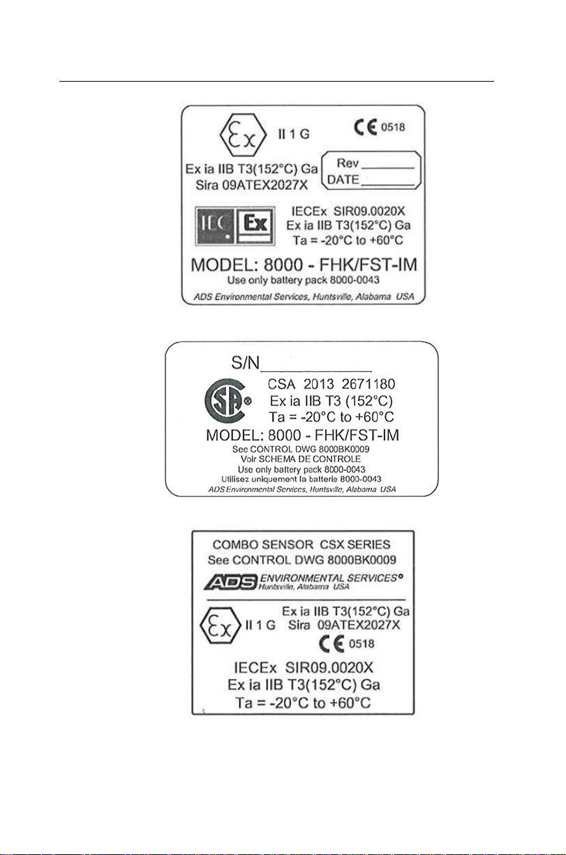
TRITON+ monitors delivered outside the U.S. must bear the
following label to substantiate conformance to ATEX and CSA
standards as certified thro ugh Sira Certification Services:
Introduction 1-15
Sira TRITON+ Certifi cation Label
CSA TRITON+ Certification Label
Sira Combo Sensor CSX Series Certif i cation Label
1-16 ADS TRITON+ Manual
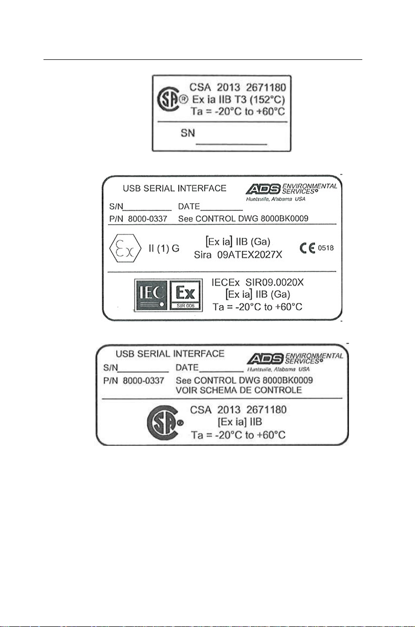
CSA Sensor Certificat i on Label
Sira USB Serial Interface Certification Label
CSA USB Serial Interface Certification Label
Introduction 1-17
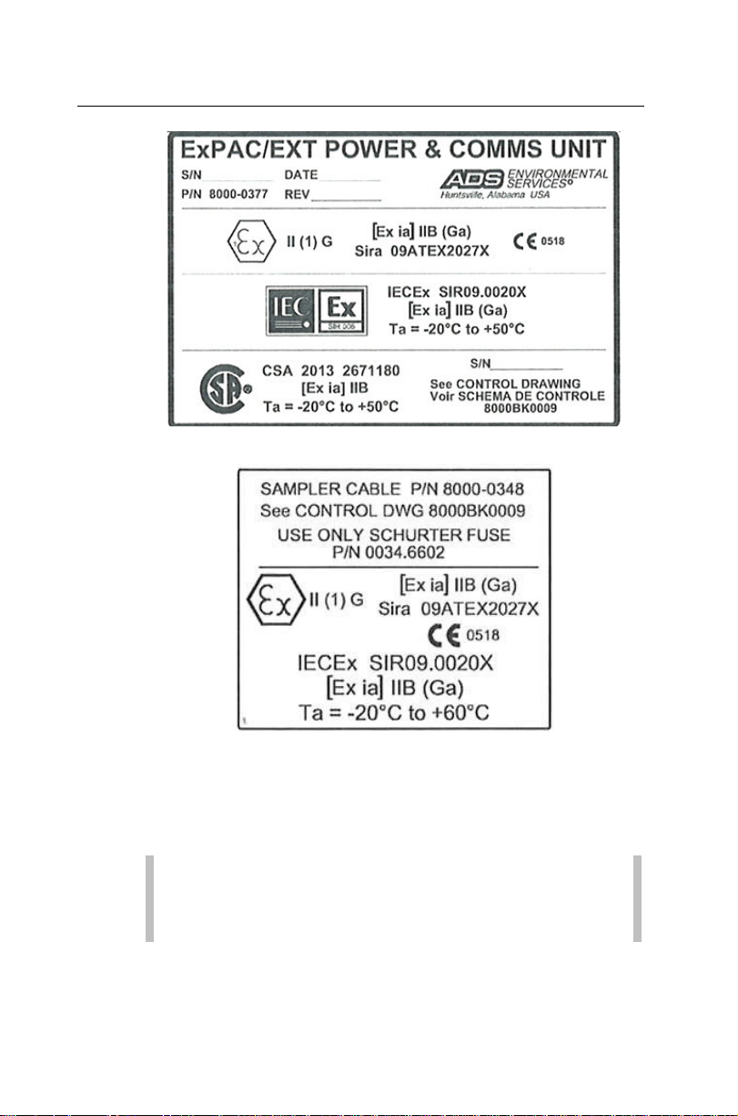
Sira ExPAC Certification Label
Sira Sampler Cable Certification Label
EC Type Examination Certificate Sira 09ATEX2027X can also be
used to substa ntiate conformance to applicable EU laws for IS
equipment. T he following page is a copy of the first page of the
certificate.
Note: This copy was current at the time of publication of
this manual. To access the latest version and entire content
of the certificate, please contact ADS.
1-18 ADS TRITON+ Manual
First page of the TRITON+ ATEX Certificate

Introduction 1-19
IECEx (International Electrotechnical Commission Explos ive) Hazardous Area Compliance
The TRITON+ is covered by certificate IECEx SIR 09.0020X
(TRITON+). Reference IECEx standards IEC 60079-0 : 2004; IEC
60079-11 : 2006; and IEC 60079-26 : 2006. This IECEx certificate
can also be used to substantiate conformance to applicable
international standards for IS equipment. The following page is a
copy of the first page of the certificate.
Note: This copy was current at the time of publication of
this manual. To access the latest version and entire content
of the certificate, please contact ADS.

1-20 ADS TRITON+ Manual
First page of the TRITON+ IECEx Certificate of Conformity

Introduction 1-21
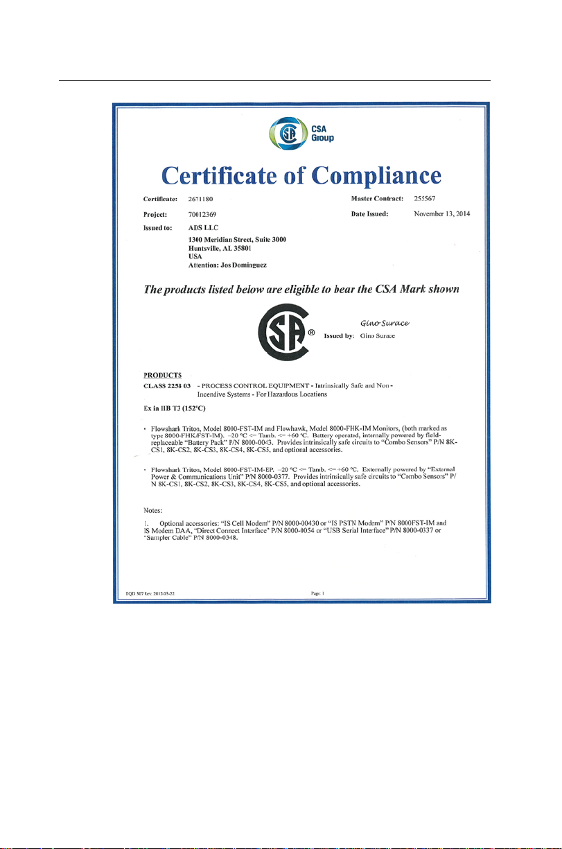
CSA Hazardous Area Compliance
The TRITON+ is covered by certificate CSA 2671180 (TRITON+
and Combo Sensors, and USB Serial Interface). Reference CSA
requirements C22.2 No. 0-10; CAN/CSA-C22.2 No. 60079-0:11;
and CAN/CSA-C22.2 No. 60079-11:11.
The following CSA certificate can also be used to substantiate
conformance to applicable Canadian standards for IS equipment:
Note: The certificate displayed on the following pages
was current at the time of publication of this manual. To
access the latest certificates, please contact ADS.
1-22 ADS TRITON+ Manual
CSA Certificate of Compliance – Page 1
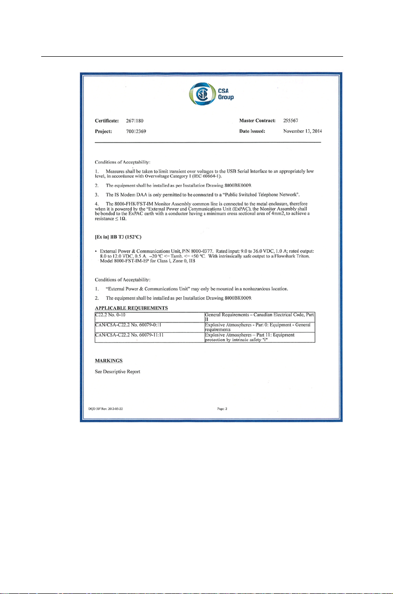
Introduction 1-23
CSA Certificate of Compliance – Page 2
 Loading...