

ADS Environmental Services QR 775016 A0 User Manual

ADS® PrimeProbe®2 User Manual
October 2009 QR 775016 A0
ADS LLC
4940 Research Drive
Huntsville, Alabama 35805
Telephone: 1-800-430-3366 / Fax: 1-800-430-6633
www.adsenv.com

PrimeProbe2 User Manual
Copyright © 2009 ADS® LLC. All rights reserved.
ADS® is a registered trademark of ADS LLC.
PrimeProbe®, PrimeLog®, and PrimeWorks® are registered trademarks of Primayer
Limited.
All other brand and product names are trademarks or registered trademarks of their
respective holders.
Notice of Proprietary Information
The information contained herein represents the latest information available at the time of
publication. ADS reserves the right to make any changes or modifications to the content
of this document, without notice, to reflect the latest changes to the equipment. No part
of this document may be reproduced in any form without the written consent of ADS.
ii

PrimeProbe2 User Manual
Table of Contents
Chapter 1 Introduction ......................................................................1
System Components.....................................................................................2
Compact.................................................................................................2
Remote...................................................................................................3
PrimeProbe2 Length Dimensions..........................................................3
Technical Specifications........................................................................4
Chapter 2 Installation ........................................................................5
Turning On the Unit.....................................................................................6
Compact Version (units acquired since June 2008)..............................6
Compact Version (units acquired prior to June 2008)..........................6
Remote Version .....................................................................................6
Site Selection ...............................................................................................7
Installation and Operational Considerations................................................8
International Standard of Flow Measurement......................................10
Mechanical Considerations for Sensor Installation ...................................11
Plastic or AC Pipes (Fitting Gate Valve).............................................11
Steel Pipes (Fitting Gate Valve) ..........................................................11
Measuring the Internal Diameter of the Pipe.............................................12
Pipe Thickness Gauge..........................................................................12
Gauging Rod........................................................................................12
Installing the PrimeProbe2.........................................................................14
Installation Procedure ..........................................................................15
Grounding the Sensor and the Converter.............................................15
Flow Direction.....................................................................................16
Connecting the Converter to the Sensor ....................................................17
Pulse Output Characteristics................................................................18
Powering-up the PrimeProbe2 Sensor.................................................19
Menu Access System.................................................................................22
Factory Presets.....................................................................................22
QUICK START...................................................................................23
Main Menu...........................................................................................23
Converter Functions...................................................................................31
Default Values .....................................................................................32
Entry Definitions................................................................................333
Chapter 3 Operation ........................................................................38
Software Setup...........................................................................................39
iii

PrimeProbe2 User Manual
Setup Wizard........................................................................................39
Chapter 4 Part Numbers..................................................................41
PrimeProbe2 (Compact) Part Numbers .....................................................42
PrimeProbe2 (Remote) Part Numbers........................................................43
Chapter 5 Battery Life......................................................................44
Chapter 6 Index… ............................................................................45
iv

C H A P T E R 1
Introduction
The PrimeProbe®2 flow meter measures flow rate in closed pipes with
clean water having a conductivity greater than 5 microsiemens. It is not
suitable for measuring wastewater, gases, petroleum, or other fluids with
low conductivity.
1
System Components
Note: Please be careful when removing the PrimeProbe2 product
from its original container. Fully inspect the equipment for
damage. If damage exists, notify the carrier and ADS immediately.
The system consists of two primary components: the insertion-type sensor
and the converter. Two types of PrimeProbe2 are available:
Compact
Remote
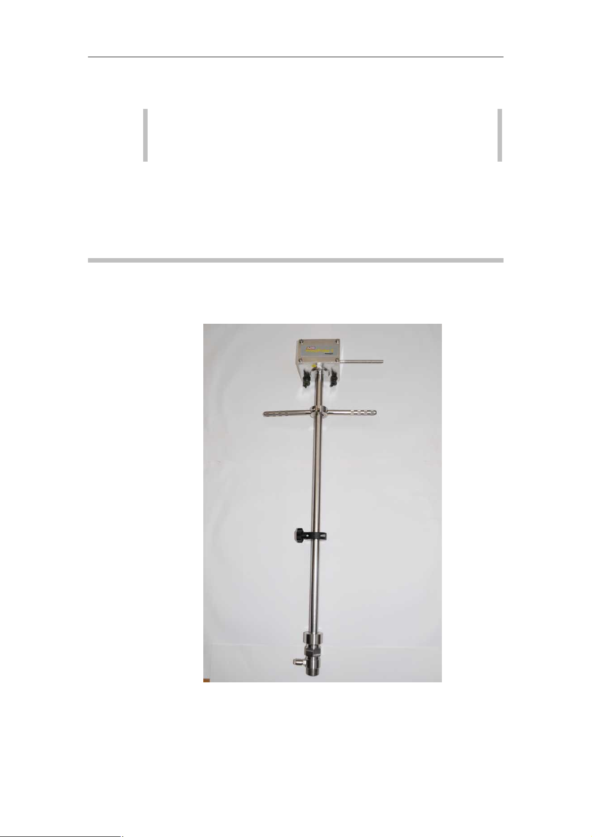
Compact
For the compact version, the converter is integrated into the sensor. This
version is battery powered.
PrimeProbe2 User Manual
2
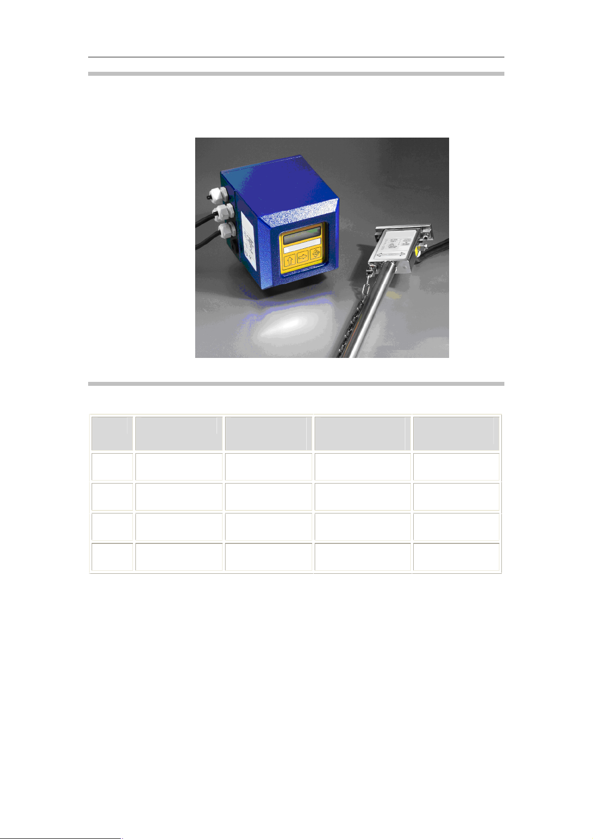
Remote
PrimeProbe2 User Manual
For the remote version, the converter connects to the sensor by a cable.
This unit can be battery or externally powered.
PrimeProbe2 Length Dimensions
Model Insertion Length Overall Length
(Compact)
Size 1 11.8 inches
(300 mm)
Size 2 19.7 inches
(500 mm)
Size 3 27.6 inches
(700 mm)
Size 4 39.4 inches
(1000 mm)
* Assumes operation on the centerline of the pipe
29.0 inches
(737 mm)
36.9 inches
(937 mm)
44.8 inches
(1137 mm)
56.6 inches
(1437 mm)
Overall Length
(Remote)
30.2 inches
(767 mm)
38.1 inches
(967 mm)
45.9 inches
(1167 mm)
57.8 inches
(1467 mm)
Use in Pipe
Sizes*
≤ 23.6 inches
(600 mm)
≤ 39.4 inches
(1000 mm)
≤ 55.1 inches
(1400 mm)
≤ 78.7 inches
(2000 mm)
3

Technical Specifications
Parameter Specification
PrimeProbe2 User Manual
Pipe Sizes
Measurement Range
Accuracy; Point
Velocity
Flow
Repeatability
Flow Determination
Measurement
Sampling
Minimum Fluid
Conductivity
Process Connection
Pipeline Pressure
Rating
3.2 to 315.0 inches (80 mm to 8000 mm) – at 1/8 pipe
diameter (insertion depth) installation
Bi-directional from 0.03 to 16.40 feet per second (0.01 m/s
to 5 m/s) (Maximum may be lower based on insertion length
and pipe position.)
±0.0066 feet per second (± 2mm/sec) or ± 2%, whichever is
the greater.
Refer to ISO 7145-1982
± 0.5% of velocity
Assumes fully developed flow profile; ISO 7145-1982
reference
Continuous or programmable from 1 to 90 seconds
5µS/cm
1-inch (25-mm) BSP (British Standard Pipe)
232 psi
Sensor Material
Body Material
Electrode Materials
Flow Temperature
Safety
Pressure Tapping
Adjustment Method
Protection
Batteries
Output: Signal
Units
Connection
Communications
PTFE (polytetrafluoroethylene)
SS304
SS316
32º to 176º F (0 to 80º C)
Probe fitted with anti-bounce chain
Female quick-release connector
5 mm Allen key (supplied by ADS) – fits all screws
IP68
Type: Lithium batteries
Life: ≤3 years (depending on sampling period and usage)
Pulses proportional to velocity/flow rate - maximum frequency
32 Hz
User-selectable
MIL-spec connector
USB
4

C H A P T E R 2
Installation
This chapter provides instructions on powering up the PrimeProbe2,
determining the appropriate length and position for the insertion sensor,
selecting a suitable location for measurement, and installing the
PrimeProbe2.
PrimeProbe2 User Manual
5

PrimeProbe2 User Manual
Turning On the Unit
ADS delivers the PrimeProbe2 in the OFF condition. The user must turn
it on before going to the first installation site, as described in the following
sections.
Compact Version (units acquired since June 2008)
1. Launch the PrimeWorks® software.
2. Connect the PrimeProbe2 to the PC/laptop running the software
using the communications cable.
3. Select the PrimeProbe2 > Shipping > Wake up menu option.
The software will initiate communications with the PrimeProbe2 to
bring it out of Sleep mode. The probe is now ready for use.
Compact Version (units acquired prior to June 2008)
1. Using the 5mm Allen key (supplied by ADS), remove the 4 screws
securing the rear cover of the converter.
2. Locate the two small switches left of center of the circuit board and
in front of the battery. Place them in the LEFT position.
3. Replace the cover and the 4 screws, and then tighten the screws
with the Allen key securely and evenly.
Remote Version
1. Using the 5mm Allen key (supplied by ADS), remove the 4 screws
securing the rear cover of the converter.
2. Locate the two small switches immediately behind the
communications jack socket. Place these switches in the LEFT
position.
3. Replace the cover and the 4 screws, and then tighten the screws
with the Allen key securely and evenly.
Note: Tighten all the screws fully to prevent water ingress from
occurring.
6

Site Selection
3.15 to 220.47 inches
3.15 to 314.96 inches
The PrimeProbe2 can be used on pipes with internal diameters from 3.15
to 314.96 inches (80 to 8000mm) at 1/8 diameter insertion depth, based on
the insertion length of the selected probe. The following table indicates
the 4 different insertion lengths of the PrimeProbe2 and the pipe sizes in
which they can operate. The PrimeProbe2 can be located at one of three
depth positions: ½-pipe diameter, 1/8-pipe diameter, or 7/8-pipe diameter.
PrimeProbe2 User Manual
Size of
PrimeProbe2
11.81 inches
(300 mm)
19.69 inches
(500 mm)
27.56 inches
(700 mm)
39.37 inches
(1000 mm)
Internal Diameters
of Pipes at 1/8
Diameter Insertion
Depth
3.15 to 78.74 inches
(80 to 2000 mm)
3.15 to 78.74 inches
(80 to 2000 mm)
(80 to 5600 mm)
(80 to 8000 mm)
Size of
PrimeProbe2
11.81 inches
(300 mm)
19.69 inches
(500 mm)
27.56 inches
(700 mm)
39.37 inches
(1000 mm)
Internal Diameters
of Pipes at 1/2
Diameter Insertion
Depth
3.15 to 23.62 inches
(80mm to 600mm)
3.15 to 39.37 inches
(80 to 1000 mm)
3.15 to 55.12 inches
(80 to 1400 mm)
3.15 to 78.74 inches
(80 to 2000 mm)
Before installing the PrimeProbe2, determine the direction of the flow in
the pipe. The PrimeProbe2 must be installed in the correct direction.
Using the symbols on the nameplate of the sensor (– to +) for reference,
the PrimeProbe2 is installed correctly when the flow in the pipe travels
from – to +.
7

PrimeProbe2 User Manual
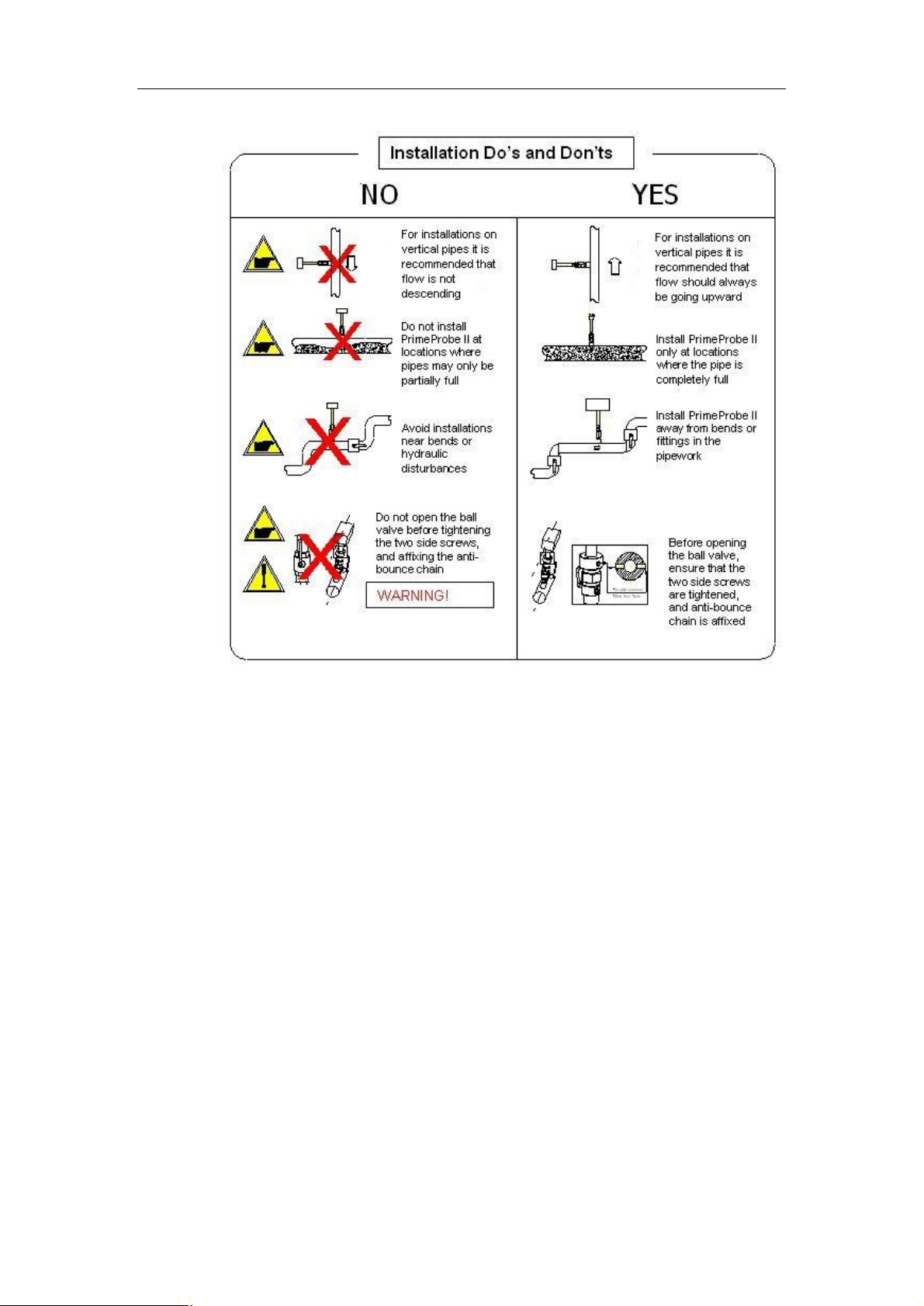
Installation and Operational Considerations
Install the sensor away from any bends in the pipe and hydraulic
fittings (disturbances). For the best results, install the sensor of the
PrimeProbe2 at a location with at least 25 times the pipe diameter
in distance of straight unrestricted pipe upstream of the sensor and
10 times the pipe diameter in distance of straight unrestricted pipe
downstream of the sensor.
Operate the PrimeProbe2 only in full pipes. The converter
performs flow calculations based on full pipe.
Before opening the valve to insert the PrimeProbe2, make sure the
safety mechanism is engaged. Some pipes are under considerable
pressure. Failure to lock-down the probe could allow pressure to
force the sensor upward like a projectile, potentially causing injury
to the installer.
Although it is not always necessary to install the sensor at the 12
o’clock position on the pipe, it is always necessary to install the
probe at a 90° angle to the length of the pipe.
The PrimeProbe2, configured with a remote converter, can receive
power from an AC mains supply. When using AC power, terminal
connections with the mains supply should be made only by
qualified technicians familiar with all current procedures and local
codes. Connection to mains power should always occur through a
RCD (residual current device) and should be the last step in the
installation process.
8
PrimeProbe2 User Manual
9

PrimeProbe2 User Manual
International Standard of Flow Measurement
The following table has been reproduced, with permission, from ISO 7145
(BS 1042) Section 2.2 1982. Complete copies are available from BSI
Publications, Linford Wood, Milton Keynes, MK14 6LE.
Type of Disturbance
Upstream from the Cross-
Section of Measurement
90-degree elbow or a t-bend 50 25
Several 90-degree coplanar
bends
Several 90-degree non-
coplanar bends
Total angle convergent 18 to
36 degrees
Total angle convergent 14 to
28 degrees
Fully-opened butterfly valve 45 25
Fully-opened plug valve 30 15
* Expressed in multiples of the diameter of the conduit.
Minimum Upstream Straight Length*
For Measurement
at the Point of
Mean Axial
Velocity
50 25
80 50
30 10
55 25
For Measurement
on the Axis of the
Conduit
10

PrimeProbe2 User Manual
Mechanical Considerations for Sensor Installation
Install the probe into the pipe through a pre-drilled 1-inch (25-mm) hole in
the pipe using a 1-inch (25-mm) Ball Valve (included). A 1.5-inch or 2inch ball valve may be used with reducers.
Installing in plastic or AC (asbestos cement) pipes with smaller diameters
and steel pipes with larger diameters requires different methods.
Plastic or AC Pipes (Fitting Gate Valve)
Plastic or AC pipes require a gate valve; however, no welding is required
to install the gate valve onto a 7.87- to 15.75-inch (200- to 400-mm)
diameter plastic or AC pipe. Simply mount a saddle to the existing pipe,
tighten the lug nuts, and connect the 1.57-inch (40-mm) gate valve. Note
that a 1.57-inch (40-mm) drill bit must be used when boring a hole in the
pipe. Do not install reducers if they will interfere with a protruding drill
bit.
Steel Pipes (Fitting Gate Valve)
To connect a gate valve to a large-diameter steel pipe, first weld a carbon
steel boss directly to the pipe. After welding the boss to the pipe and
pressure-testing the weld, attach a 1.57-inch (40-mm) gate valve.
Note: A carbon steel boss cannot be welded effectively to a
ductile iron pipe. When using the PrimeProbe2 with ductile iron
pipes, use a pipe saddle.
11
 Loading...