

ADS Environmental Services QR 775012 A4 User Manual

IETG Intrinsically-Safe
FlowHawk
Installation, Operation, and
Maintenance Manual
October 2012 QR 775012 A4
Cross Green Industrial Estate
IETG Ltd.
Cross Green Way
Leeds
LS9 0SE
England
+44 (0)8450 179 333
www.ietg.co.uk

ii IETG FlowHawk Manual
2012 ADS
LLC. All rights reserved.
ADS , Profile, IntelliServe, FlowHawk , and Qstart are
either trademarks or registered trademarks of ADS LLC.
Enfora is a trademark of Enfora, Incorporated.
Microsoft and Windows are registered trademarks of Microsoft
Corporation.
Scotchkote is a trademark of 3M.
Teflon is a registered trademark of E.I. du Pont de Nemours and
Company.
Telog is a registered trademark of Telog Instruments.
All other brand and product names are trademarks or registered
trademarks of their respective holders.
Notice of Proprietary Information
The information contained herein represents the latest information
available at the time of publication. ADS LLC reserves the right to
make any changes or modifications to the content of this document,
without notice, to reflect the latest changes to the equipment. No
part of this document may be reproduced in any form without the
written consent of ADS LLC.

Table of Contents iii
Table of Contents
Chapter 1 Introduction……… ................... 1-1
Intrinsic Safety ............................................................... 1-2
FlowHawk System Certification .............................. 1-2
Installation and IS Considerations ........................... 1-5
Special Conditions for Safe Use .............................. 1-5
Maintenance Restrictions ............................................... 1-7
Warnings, Certifications, GSM/GPRS Compliance,
and Conformity ................................................ 1-9
Changes or Modifications ....................................... 1-9
Control Drawing .................................................... 1-10
European ATEX Hazardous Area Compliance ..... 1-12
IECEx (International Electrotechnical
Commission Explosive) Hazardous Area
Compliance .................................................... 1-20
Declaration of Conformity .................................... 1-23
Installation and Configuration ...................................... 1-25
Product Warranty ......................................................... 1-27
New Product Warranty .......................................... 1-27
Out-of-Warranty Product Repairs ......................... 1-28
Trouble s hooting Fee ............................................. 1-28
Shipping ................................................................ 1-28
European Service Centre ....................................... 1-29
Chapter 2 System Overview ..................... 2-1
FlowHawk Flow Monitor ............................................... 2-4
Communications ...................................................... 2-4
Processor Board ...................................................... 2-8
Connector Ports ....................................................... 2-9
Power .................................................................... 2-11
Sensors ......................................................................... 2-14
Peak Combo Sensor .............................................. 2-14
Ultrasonic Depth Sensor ....................................... 2-17
Surface Combo Sensor .......................................... 2-19
Slimline Peak Combo Sensor ................................ 2-23

iv IETG FlowHawk Manual
Chapter 3 Sensor Installation and
Connection………………… ................... 3-1
Investigating Site Characteristics ................................... 3-4
Flow Hydraulics ...................................................... 3-4
Pipe and Manhole Characteristics ........................... 3-5
Installing the Sensors in the Pipe .................................... 3-7
Standard Installation................................................ 3-7
Special Installations .............................................. 3-33
Securing the Sensor Cables in the Pipe and Manhole .. 3-53
Connecting the Sens ors to the Monitor ........................ 3-56
Securing the Dryer Tube to the Monitor ............... 3-58
Chapter 4 Communication… .................... 4-1
GSM-Based Wireless Communication ........................... 4-3
Installing the GSM Module ............................................ 4-5
Gathering Pa rts and Supplies .................................. 4-6
Installing the Wireless Antenna ............................... 4-8
Installing the SIM Card ......................................... 4-13
Installing the GSM Module ................................... 4-17
Installing an EM U ........................................................ 4-20
Installing the Communication Cable ..................... 4-20
Installing the EMU ................................................ 4-26
Installing an EM UX ..................................................... 4-40
Installing the Communication Cable ..................... 4-40
Installing the EMUX ............................................. 4-41
Connecting the Co mmunicati on Cable to the
Monitor .......................................................... 4-46
Installing a Wireless Antenna ................................ 4-47
Connecting the RTU to the EMUX ....................... 4-49
Providing E xternal Power to the EMUX ............... 4-49
Connecting to the Monitor in the Field (Direct
Connection) .................................................... 4-52

Table of Contents v
Chapter 5 External Power…. .................... 5-1
Installation ...................................................................... 5-2
DC Power Requirements and Consumption ............ 5-3
Installing and Wiring the IETG-Supplied Power
Supply to the EMU or EMUX ......................... 5-4
Chapter 6 Configuration and Activation .. 6-1
Hardware and Software Compatibility .................... 6-2
Configuring the Monitor Location ................................. 6-3
Starting the Profile Software ................................... 6-4
Creating a Monitor Location ................................... 6-5
Adding a Second Monitoring Point ....................... 6-10
Creating an Installation Table ............................... 6-11
Selecting and Editing Devices ............................... 6-17
Setting the Communication Parameters ........................ 6-58
Activating the Monitor ................................................. 6-63
Setting Up the RTU to Retrieve the Current Data
through Modbus ............................................. 6-67
Designating the Data for Retrieval ........................ 6-67
Verifying the Mo dbus Output Data ....................... 6-67
Running Sensor Diagnostics ......................................... 6-69
Ultrasonic Depth Diagnostics ................................ 6-71
Pressure Depth Diagnostics ................................... 6-74
Velocity Diagnostics ............................................. 6-76
Smart Depth Diagnostics ....................................... 6-79
Temperature Diagnostics....................................... 6-82
Activating the Monitor .......................................... 6-84
Collecting Data from the Monitor ................................ 6-86
Upgrading the Monitor Firmware ................................. 6-95
Viewing Diagnostic a nd Data Logs .............................. 6-98
Chapter 7 Monitor Installation .................. 7-1
Mounting the Monitor on Manhole Rung ....................... 7-2
Mounting the Monitor Handle to the Manhole Wall ...... 7-3

vi IETG FlowHawk Manual
Chapter 8 Maintenance and
Troubleshooting…………. ..................... 8-1
Maintaining the System Co mponents ............................. 8-2
Gathering Replacement Parts and Supplies ............. 8-2
Inspecting the Monitor ............................................ 8-3
Inspecting, Cl eaning, and Handling the Senso rs ... 8-17
Replacing the SIM Card and Desiccant in the
GSM Module ................................................. 8-21
Replacing EMU Components ................................ 8-25
Replacing the SIM Card in the EMUX ................. 8-30
Replacing the Regulator and Fuses in the
Monitor .......................................................... 8-31
Troubleshooting ........................................................... 8-38
General Monitor Problems .................................... 8-39
Communication Problems ..................................... 8-43
Ultrasonic Depth Subsystem ................................. 8-47
Upward Depth Subsystem ..................................... 8-52
Peak Velocity Subsystem ...................................... 8-55
Surface Velocity Subsystem .................................. 8-58
Pressure Depth Subsystem .................................... 8-60
Temperature Subsystem ........................................ 8-61
Appendix A Specifications….. .................. A-1
FlowHawk Flow Monitor ....................................... A-1
Intrinsically-Safe Sensors ....................................... A-4
Direct Connect Cable ........................................... A-11
Wireless GSM Module ......................................... A-12
External Modem Unit ........................................... A-13
External Modem Unit/Multiplexer ....................... A-14
Power Supply ....................................................... A-15
Appendix B Part Numbers…… ................. B-1
Appendix C Monitor Activity Codes ......... C-1

Table of Contents vii
Appendix D Modbus/EMUX Configuration
and Diagnostics…………. ..................... D-1
Setting up PC-to-EMU Communication ................. D-2
Running the Onboar d Diagnostics .......................... D-3
Modbus Data Registers .......................................... D-7
EMUX LED Window .......................................... D-10
Appendix E System Configuration and
Setup to Support the Telog Ru-33 ....... E-1
Configuring the Monitor to Support the Ru-33 ....... E-2
Connecting the Monitor to the Ru-33 ...................... E-2

C H A P T E R 1
Introduction
The IETG Intrinsically-Safe FlowHawk™ flow monitor (powered by
®
) measures open channel flow in sanitary sewers, storm
ADS
sewers, combined sewers, and other environments to assist
municipalities and other industry in address ing the following issues:
Planning sewer systems (sizing and rehabilitation)
Reducing infiltration and inflow (I/I)
Monitoring combined sewer overflows (CSOs)
Detecting and monitoring surcharges
1-1
Managing inter-agency billing
Monitoring sewage handling facilities (wastewater treatment
plants and pump stations)
The battery- or externally-powered FlowHawk monitor provides
exceptional accuracy and reliability in measuring open-channel flow
depth and velocity to determine flow rate (quantity) in pipes. This
flow data is the essential element required to successfully perform
investigative, analytical, and reporting activities.
This manual offers detailed instructions on installing, maintaining,
and troubleshooting the FlowHawk flow monitor, sensors, and
communication hardware.

1-2 IETG FlowHawk Manual
Intrinsic Safety
Intrinsic safety is an electronic hardware protection concept that
ensures there a re no conditions under which the equipment can
operate that could cause a release of energy sufficient to ignite a
hazardous gas or dust mixture. Devices that meet the low power,
current-limited design criteria are deemed Intrinsically Safe (IS).
Special design, testing, quality, and inspection rules apply to
manufacturers and users of IS equipment due to the critical nature
of their deplo yment in hazardous areas. Areas where hazardous
conditions can be expected to be present on a constant basis are
classified (rated) as Class I, Division 1 or Zone 0.
The FlowHawk flow monitor (Models 8000-FHK and 8000-FHK60C) is certified to ATEX (Atmosphere Explosibles) standards in
Europe and is certified for use in all classified (hazardous) sanitary
sewer and industrial hazardous areas. Many res t-of world countries
accept ATEX certification in lieu of their country-specific
requirements. It is the customer’s responsibil ity to ensure that
the certification(s) provided for the IETG equipment meets the
applicable regulatory requirements.
Note: FlowHawk models include only the 8000-FHK and
8000-FHK-60C.
FlowHawk System Certification
The FlowHawk unit and associated telemetry equipment are
certified for use only with approved sensors, communication cables,
and telemetry equipment. Connection of any non-approved devices
could result in unsafe operation and will immediately void the
warranty and IS certification.
Note: Connecting the Te l og® Ru-33 to the IETG
FlowHawk is an approved application and, therefore, will
not void the Fl owHawk warranty. However, because the

Introduction 1-3
Telog unit is not IS certified, the installation will not be
considered intrinsically safe if the Ru-33 is installed in the
manhole with the monitor.
Sensors
The FlowHawk monitor supports several approved IS sensors that
vary in measurement methodology, red undancy, and other features.
The monitor is approved for accommodating up to two of the same
or different types of IS sensors. Following are the approved IS
sensors:
Peak Combo Sensor Performs upward ultrasonic depth,
pressure depth, and peak velocity measurement and mounts at
or near the bottom (or invert) of the pipe under the flow surface
(p/n 8K-CS4-05-35, 8K-CS4-15-35, or 8K-CS4-30-1H).
Surface Combo Sensor Performs downward ultrasonic
depth, surcharge pressure depth, surcharge peak velocity, and
surface velocity measurement and mounts at the top (or
soffit/crown) of the pipe above the flow (p/n 8K-CS5-V2-05-30
or 8K-CS5-V2-15-30).
Ultrasonic Depth Sen sor (ultrasonic and optional
pressure depth only) Performs downward ultrasonic depth
and pressure depth (optional) measurement and mounts at the
top (or soffit/crown) of the pipe above the flow (p/n 8K-CS3V0-00-30, 8K-CS3-V0-05-30, or 8K-CS3-V0-15-30).
Slimline Peak Combo Sensor Performs upward ultrasonic
depth and peak velocity measurement and mounts at or near the
bottom of the pipe under the flow surface (p/n 8K-CS4-35).
Extension cables are available for these sensors in lengths up to 91
meters (300 ft).
Note: Detailed descriptions and specifications for the
sensors are available in Chapter 2, System Overview, and
Appendix A, Specifications.

1-4 IETG FlowHawk Manual
Power
The FlowHawk flow monitor can be powered by an internal 12-volt
IS battery pack (p/n 8000-0043) or an external DC power source
through an external modem unit (EMU, p/n 3800-0148) or
EMU/multiplexer (EMUX, p/n 106226E)).
Telemetry
Wireless communication is available for the FlowHawk monitor via
connection to an IS quad-band GSM/GPRS module (p/n 8000-
0052), an EMU (p/n 3800-0148), or an EMUX (p/n 106226E).
Connecting the FlowHawk to the Telog RTU (Model Ru-33) also
supports wirel ess communication via the Telog “passthrough”
mode.
The GSM module is certified for installation and operation in the
hazardous area and receives power from the FlowHawk. The
antenna may be located either inside or outside the manhole;
however, IETG recommends installing the antenna outside the
manhole to maximize signal strength. Several antenna models are
available to mitigate signal strength is s ues.
The EMU is mounted outside the hazardous area and receives
power from an external DC power source supplied by the user. It is
delivered with the antenna installed on the inside of the EMU
enclosure. However, the antenna may require installation outside
the EMU if the material and/or construction of the enclosure and/or
housing in which the EMU enclosure is installed imped es the signal
from the wireless provider.
The EMUX is mounted outside the hazardous area and receives
power from an external DC power source supplied by the user. It is
delivered without an antenna; therefore, an antenna must be
attached to the EMUX. However, it may r e quire installation outside
the enclosure in which the EMUX is installed if the material and
construction of the enclosure impedes the signal from the wireless
provider.
The Telog Ru-33 is mounted next to the FlowHawk in the
hazardous area and connected to the monitor using the Triton-Telog
Comm Cable (p/n 8000-0054-01). However, please note that,

because the Telog unit does not possess IS certification, the
installation will not be considered intrinsically safe if the Telog unit
is installed in the manhole with the monitor.
Installati on a nd IS Considerations
When installing the FlowHawk flow monitor, carefully follow any
local regulations for the installation of IS equipment. For example,
many clients only allow the use of special hazardous area tools
(flashlights, radios, etc.) in manholes. Some clients will not allow
the use of an electric drill, either battery-powered or AC-powered,
in a manhole. Und er these conditions, use air (pneumatic) tools.
When in doubt as to the applicable regulations, check with the client
or the client’s designated safety representative.
Special Conditi ons f or Safe Use
During the ATEX /IECEx approval process, certain conditions are
set forth that must be observed when using the certified equipment.
These “Special Conditions for Safe Use” can be found in the body
of each ATEX Certification (referenced in this manual), as well as
on a page attached to the Declaration of Conformity. A summar y of
these Safe Use Instructions is as follows:
Introduction 1-5
• The Models 8000-FHK and 8000-FHK-60C shall use only the
12-volt IS Battery Pack (p/n 8000-0043) for internal power.
• The Models 8000-FHK and 8000-FHK-60C shall be used in
the hazardous area only when fully assembled. Do not perform
any maintenance of internal parts, replacement o f battery packs,
or replacement of fuses unless the unit is located in a safe area.
• Only approved sensors shall be connected to the Models 8000-
FHK and 8000-FHK-60C: sensor types 8K-CS1, 8K-CS3, 8KCS4, and 8K-CS5.

1-6 IETG FlowHawk Manual
Note: The 8K-CS1 is no longer available; however, IETG
will continue to provide support for this sensor.
• As aluminum is used at the acce ssib le surface of this unit, in the
event of rare incidents, ignition sources due to impact and
friction sparks may occur. This shall be considered when it is
being installed, particularly in locations that require equipment
with a Group II Ga level of protection.
• The only communication devices that may be connected to the
COMM conne ctor on the FlowHawk are the GSM Wireless
Module (p/n 8000-0052), the EMU/EMUX Communication
Cable (p/n 106227B), and the Direct Connect Interface (p/n
8000-0054)
Note: The Triton-Telog Comm Cable (p/n 8000-0054-01)
also may be connected to the COMM connector on the
FlowHawk to provide communication between the Telog
Ru-33 and the monitor. However, since the Ru-33 is not
certified for IS operation, an installation involving a
connection between these units will not be considered
intrinsically safe, unless the Telog unit is installed outside
the hazardous area.
• Never rub any plastic parts (specifically, the ABS plastic
connector potting boots and the Peak Combo Sensor and
Slimline Peak Combo Sensor housings) with a dry cloth. This
could result in the buildup of dangerous s t atic charges.
• Parts of the enclosure may be non-conducting and may generate
an ignition-capable level of electrostatic charge under certain
extreme conditions. Therefore, do not install this equipment in
a location where it may be subject to external conditions (such
as high-pressure steam or dust) that may cause a buildup of
electrostatic charge on non-conducting surfaces.

Maintenance Restrictions
As mentioned earlier, all FlowHawk flow monitors are
manufactured to meet IS standards. The monitor’s IS certification
can be voided instantly if proper maintenance and service
procedures are not followed. IETG must restrict certain
maintenance tasks to IETG IS-certified technicians.
IETG-certified technicians carefully inspect and document their
repairs of IS monitors. This inspection and documentation process
provides legal protection should the monitor's performance or safety
be in question.
If you experience trouble with this equipment, please refer to this
manual for troub l eshooting guidelines. The following maintenance
procedures may be performed in the field, but they must be
performed as described in this manual:
Install and swap monitor
Install and swap sensors
Install and swap battery pack
Introduction 1-7
Swap fuses in power regulator in monitor
Install and swap GSM wireless module
Install and swap EMU and modem in EMU
Install and swap EMUX
Install and swap SIM cards (EMU, EMUX, and GSM module)
Replace pressure depth sensor dryer tube and desiccant beads
Replace desiccant pack (GSM module)
Clean sensors
Confirm sensors
Note: Please note that, in all applications, only IETG IScertified Service Technicians are authorized to perform
component-level service on the FlowHawk.

1-8 IETG FlowHawk Manual
If you have any questions about the procedures, warranty
information, or the level of service you are allowed to perform on a
monitor, contact IETG through the contact information listed at the
end of this chapter.

Introduction 1-9
Warnings, Certifications, GSM/GPRS Compliance, and Conformi ty
Manhole and sewer system work involves confined space entry and
is inherently dangerous. Therefore, installers and technicians
should comply with all local and governmental regulations
concerning confined space entry.
In addition, personnel installing and maintaining this equipment
should follow all gui delines presented in this manua l concerning
monitor installation and maintenance. Failure to strictly adhere to
these guidelines can result in personal injury and/or damage to the
monitor.
Note: The certifications included in this chapter identify
the FlowHawk, IS GSM Module, combo sensors, and
Direct Connect Interface as products of ADS. The
FlowHawk and its communication modules and sensors are
designed specifically for IETG by ADS.
Changes or Modifications
Changes or modifications to the FlowHawk flow monitor not
expressly approved by the party responsible for compliance will
void the IS certification.
Personnel performing installation of the FlowHawk flow monitor
should carefully follow the guidelines contained in this manual
when installing and maintaini ng the monitor. Failure to strictly
adhere to these guidelines can result in personal injury and can
cause damage to the monitor, which would invalidate its warranty.
The FlowHawk flow monitor is designed to be installed in
combined and sanitary sewer lines and manholes. This installation
work is inherently dangerous. All applicable safety guidelines
1-10 IETG FlowHawk Manual
should be followed and carried out by at least two fully trained and
qualified persons.
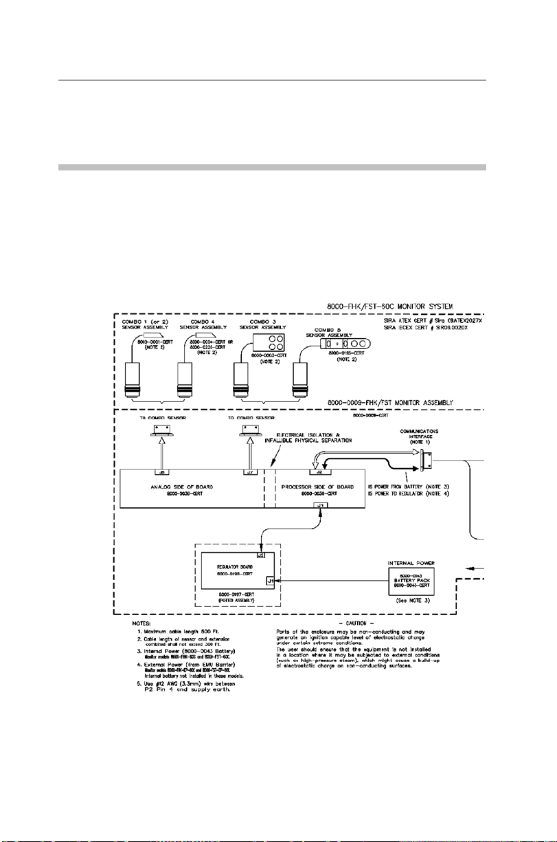
Control Drawing
This drawing depicts the interconnections allowed for the
FlowHawk. It is intended for use by inspection professionals for
audit certificate compliance; however, it is a good tool to
understand the FlowHawk flow monitoring system structure. This
drawing is divided in two sections with a match point indicated.
Control Drawing – Part 1 (right side from part 1 continues on part 2)
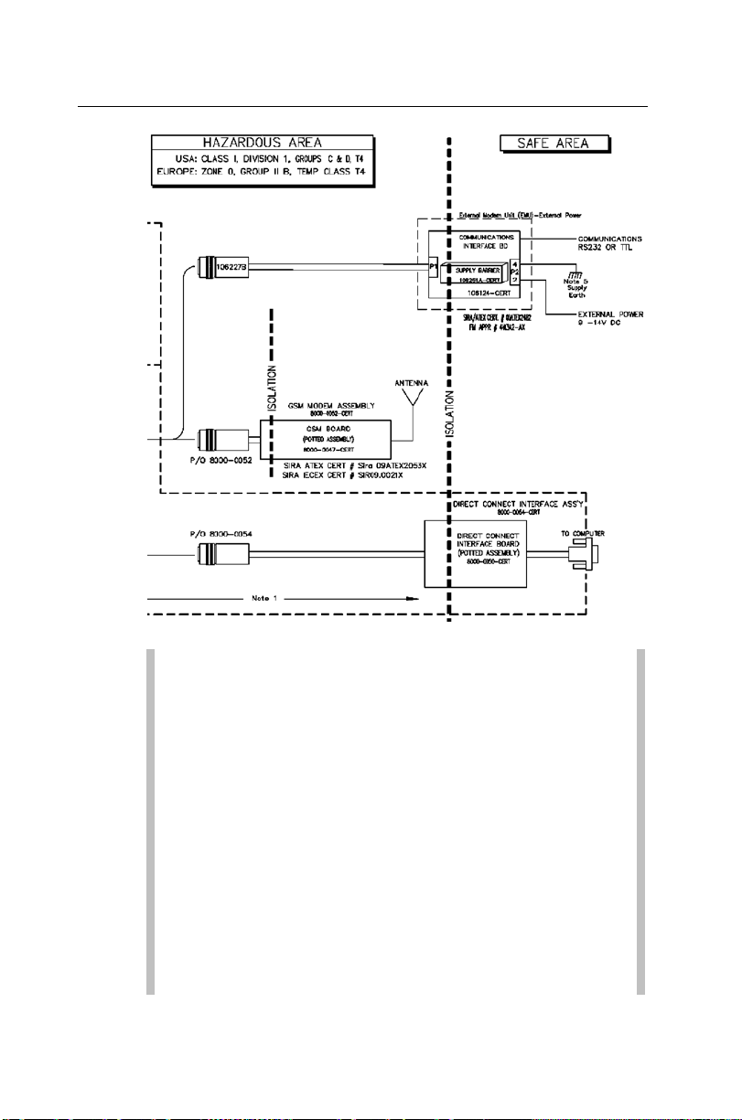
Introduction 1-11
Control Drawing – Part 2 (left side on 2 cont i nues from drawing 1)
Note: These are excerpts from an agency controlled
document for ill ustration purposes only. Changes to the
base controlled document require the approval of the
certification body. For a full-size PDF copy of this
drawing, please contact IETG and request drawing number
8000BK0009-CERT.
Note: The Telog R u-33 can be connected to the COMM
port on the FlowHawk monitor using the Telog-Triton
Comm Cable (p/n 8000-0054-01). However, this
configuration has not been included on thi s drawing
because the Telog unit is not certified for IS opera tion.
Therefore, an installation involving this configuration will
be considered intrinsically safe, unless the Ru-33 is
installed outside the hazardous area.

1-12 IETG FlowHawk Manual
GSM/GPRS Modem Information
Wireless telemetry is provided via attachment of the GSM Module
to the FlowHawk monitor. The GSM Module contains a thirdparty, R&TTE-CE-certified, commercial GSM/GPRS modem.
Integration of the modem into the GSM Module was performed in
accordance with guidelines set forth in the third party’s Integration
Manual in order to maintain the FCC approval.
Use of the modem, as installed in the GSM Module, is considered a
Mobile wireless application, meaning the module is capable of
being moved between locations. However, it is NOT considered a
Portable device, which indicates it is used in close proximity to a
user’s body (like a handset). Users of the GSM Module must
maintain a distance from the antenna of at least 200 mm (7.87 in)
when the unit is operational.
Users cannot provide their own antennas due to strict limitations on
antenna gains and other variables that may produce a dangerous RF
condition and violate IS and European safety requirements. Only
antennas provided by IETG for use with the GSM Module may be
used.
Compliance with applicable European Directives is demonstrated
through the following marking:
CE 0889
This marking indicates that the Enfora GSM0308 OEM module is
entirely encapsulated to meet IS requirements. The o nly useraccessible part of the modem is the SIM card carrier.
European ATEX Hazardous Area Compliance
The following instructions apply to equipment covered by
certificates numbered Sira 09ATEX2027X (FlowHawk, Direct
Connect Interface, and Combo Sensors CSX Series),
09ATEX2053X (IS GSM modem), and 03ATEX2482 (IS Comm
Interface). Reference European ATEX Directive 94/9/EC, Anne x
II, 1.0.6:

Introduction 1-13
The equipment may be used with flammable gases and vapors
with apparatus groups IIA and IIB and with temperature classes
T3 (152
o
C), T4, T5, and T6.
The equipment is only certified for use in ambient temperatures
in the range of -20
o
C to +60oC and should not be used outside
this range.
The certificate number has an ‘X’ suffix, which indicates that
special conditions apply to installation and use. Those
installing or inspecting this equipment must have access to the
contents of the certificate.
Installation shall be carried out in accordance with the
applicable code of practice by suitably-trained personnel.
Repair of this equipment shall be carried out in accordance
with the applicable code of practice.
If the equipment is likely to come into contact with aggressive
substances, it is the responsibility of the user to take suitable
precautions that prevent it from being adversely affected, thus
ensuring that the type of protection is not compromised.
Aggressive substances such as acidic liquids or gases that
may attack metals or solvents that may affect polymeric
materials
Suitable precautions such as regular checks as part of
routine inspections or establishing from the material’s data
sheet that it is resistant to specific chemicals
There are no special inspections or maintenance conditions
other than a periodic check.
FlowHawk monitors and GSM modem modules delivered to
Europe must bear the following label to substantiate
conformance to ATEX standards as certified through Sira
Certification Services:
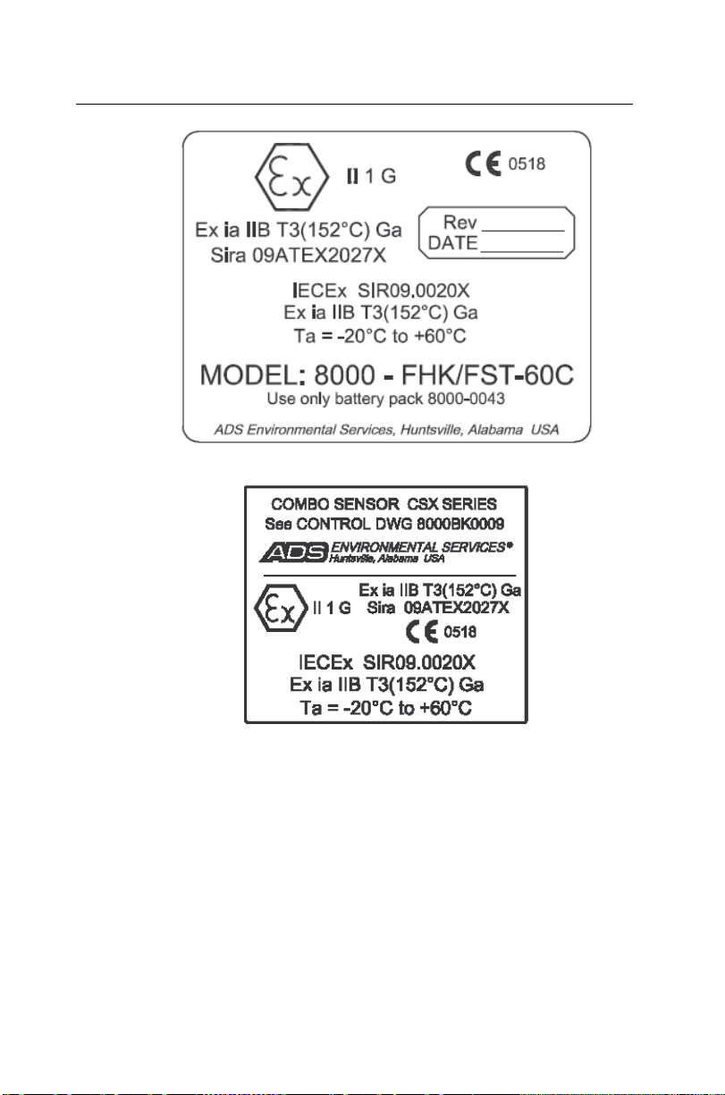
1-14 IETG FlowHawk Manual
Sira FlowHawk Certification Label
Sira Combo Sensor CSX Series Certif i cation Label
Introduction 1-15
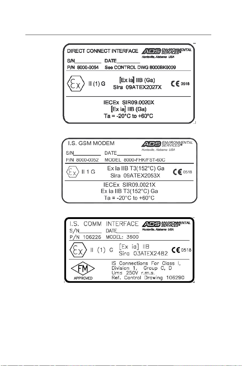
Sira Direct Connect Interf ace Certification Label
Sira GSM Certifi cation Label
Sira Communicat i on I nterface (EMU/EMUX) Certification Label
EC Type Examination Certificates Sira 09ATEX2027X, Sir a
09ATEX2053X, and Sira 03ATEX2482 can also be used to
substantiate conformance to applicable EU laws for IS equipment.

1-16 IETG FlowHawk Manual
The following pages provide a copy of the first page of each
certificate.
Note: These copies were current at the time of
publication of this manual. To access the latest version
and entire content of each certificate, please contact IETG
Ltd.
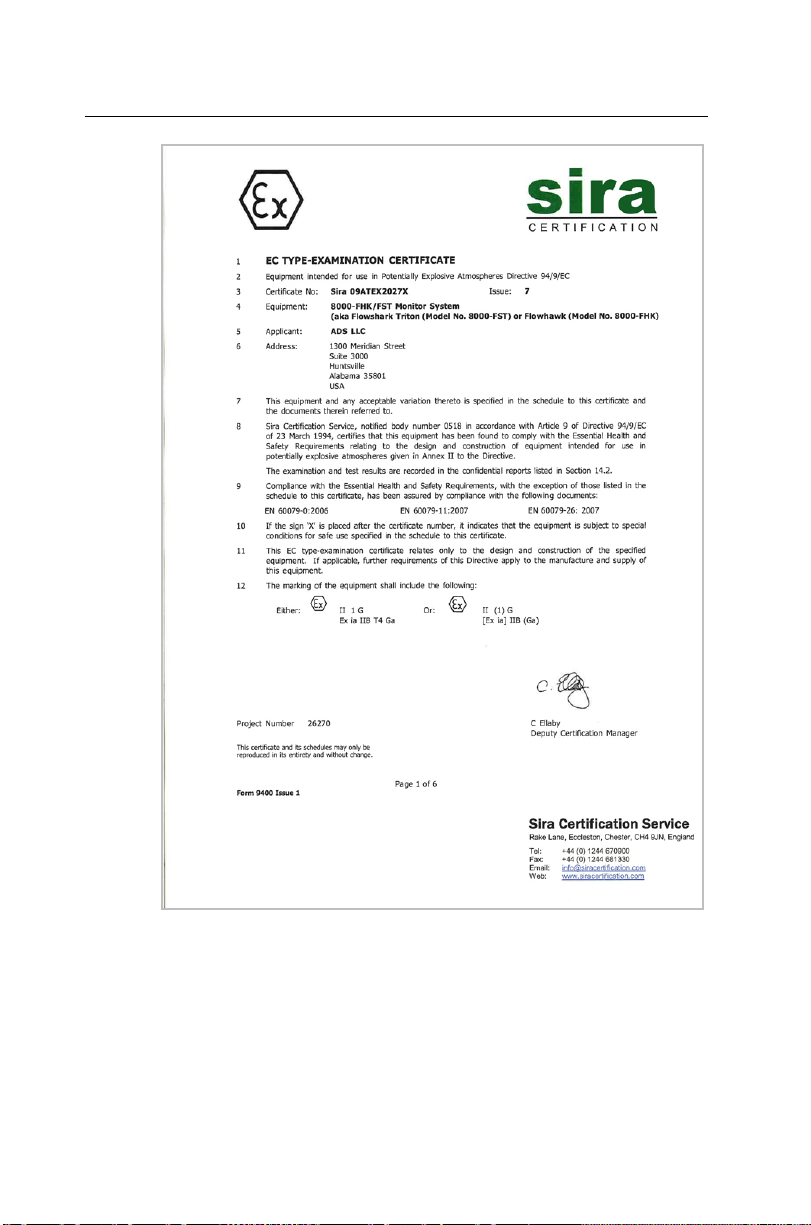
Introduction 1-17
First page of the FlowHawk ATEX Certificate
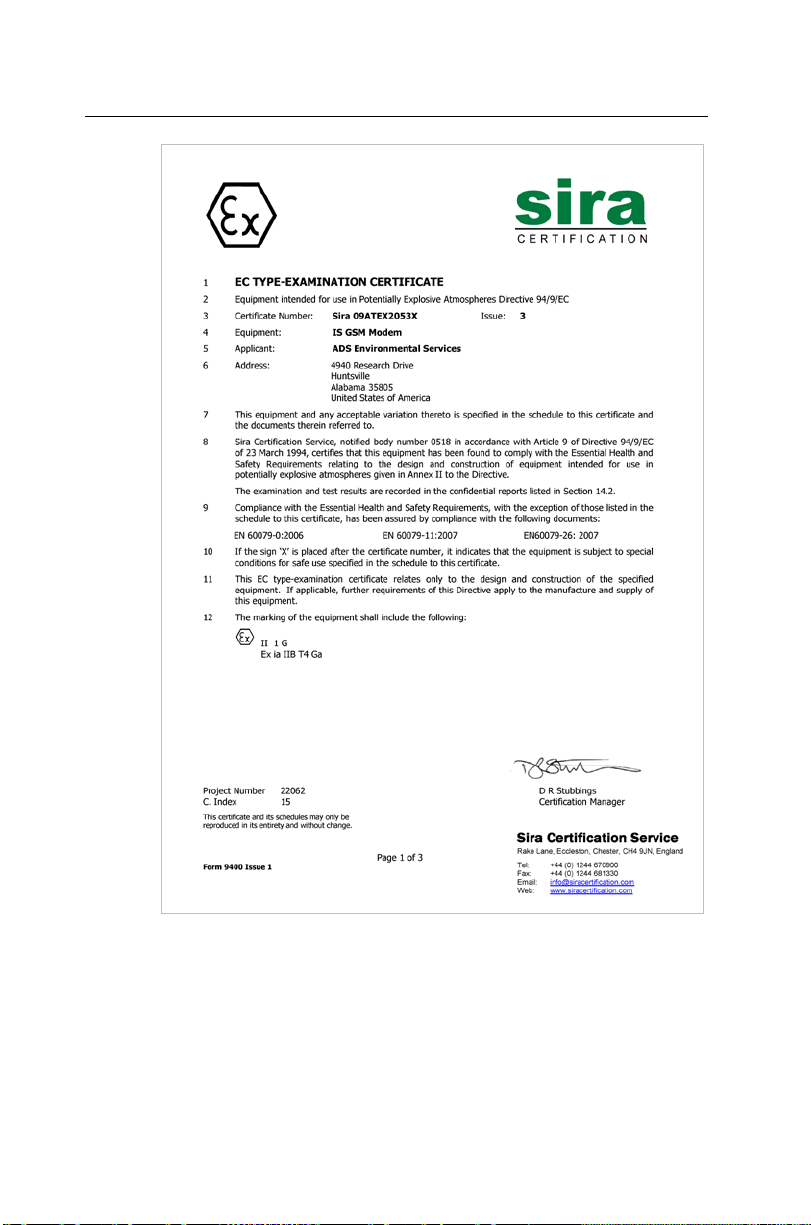
1-18 IETG FlowHawk Manual
First page of the GSM Module ATEX Certificate
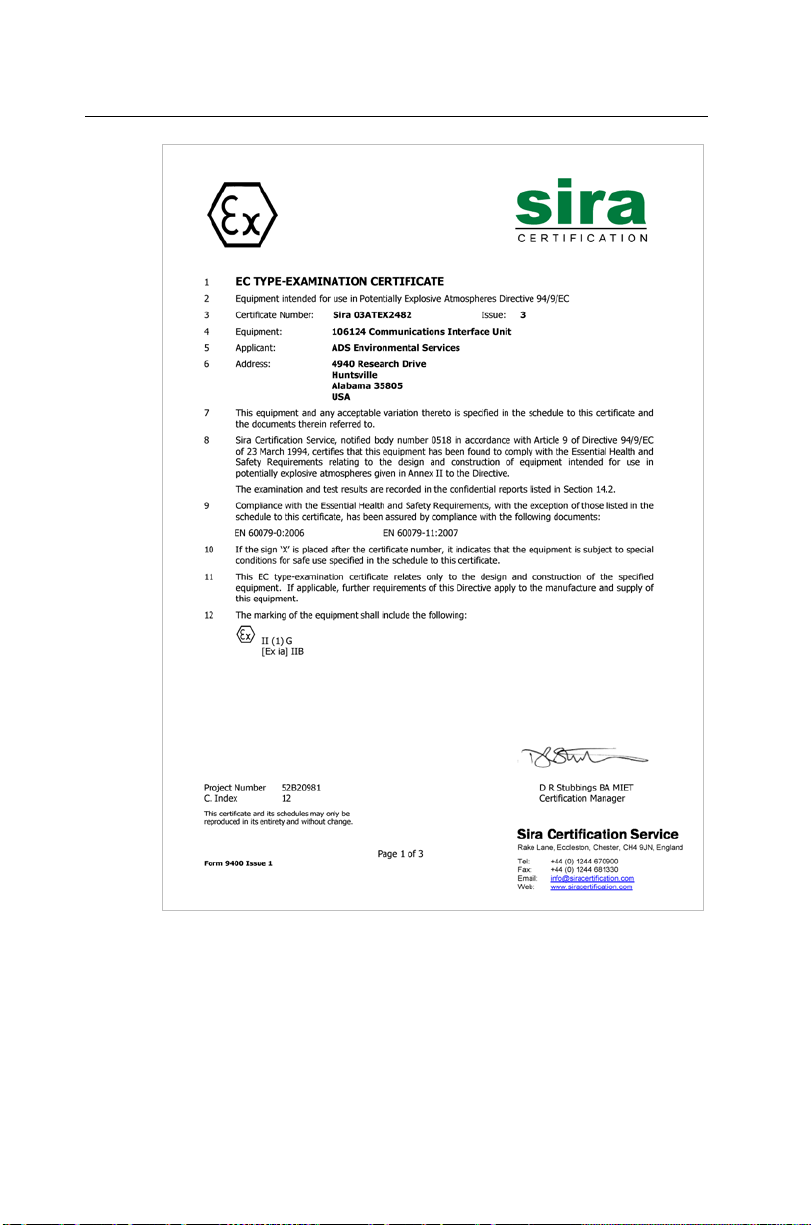
Introduction 1-19
First page of the Communications Interface Unit (from the EMU/EMUX)
ATEX Certificate

1-20 IETG FlowHawk Manual
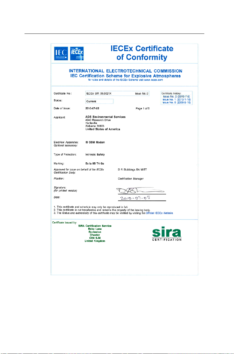
IECEx (International Electrotechnical Commission Explos ive) Hazardous Area Compliance
The FlowHawk i s covered by certificates IECEx SIR 09.0020X
(FlowHawk) and IECEx SIR 09.0021X (IS GSM modem).
Reference IECEx standards IEC 60079-0 : 2004; IEC 60079-11 :
2006; and IEC 60079-26 : 2006. These IECEx certificates can also
be used to substantiate conformance to applicable international
standards for IS equipment. The following pages provide a copy of
the first page of each certificate.
Note: The copies were current at the time of publication
of this manual. To access the latest version and entire
content of each certificate, please contact IETG.
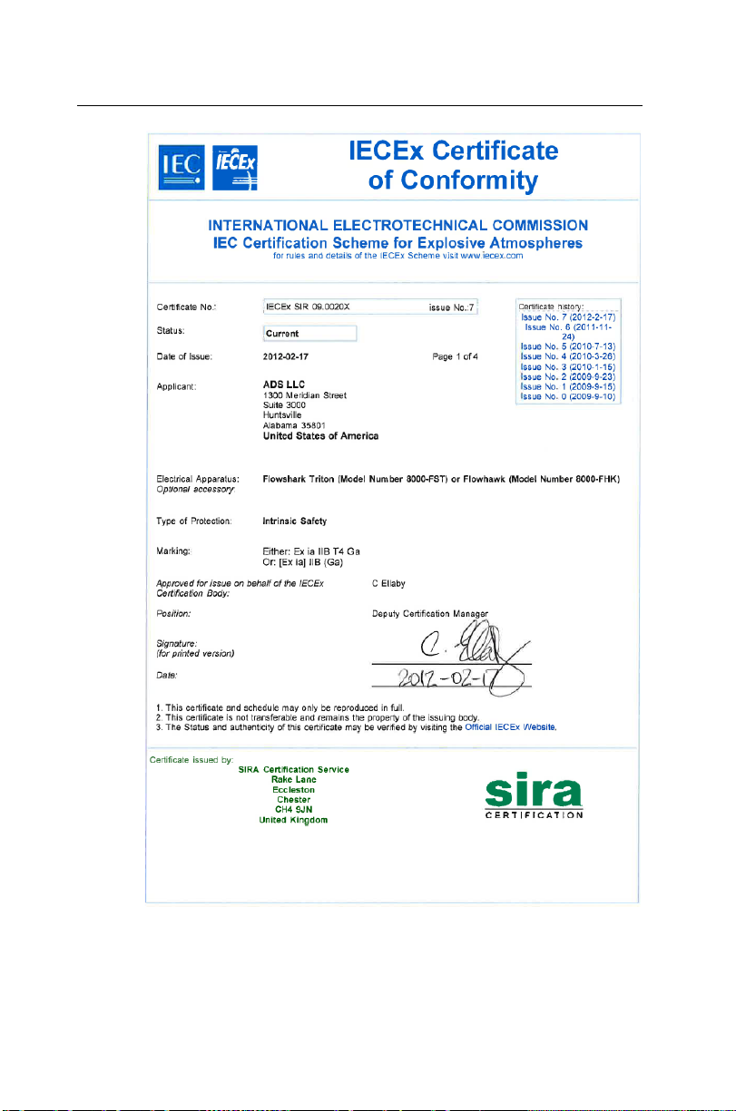
Introduction 1-21
First page of the FlowHawk IECEx Certific at e of Conformity
1-22 IETG FlowHawk Manual
First page of the GSM Module IECEx Certifi cate of Conformity
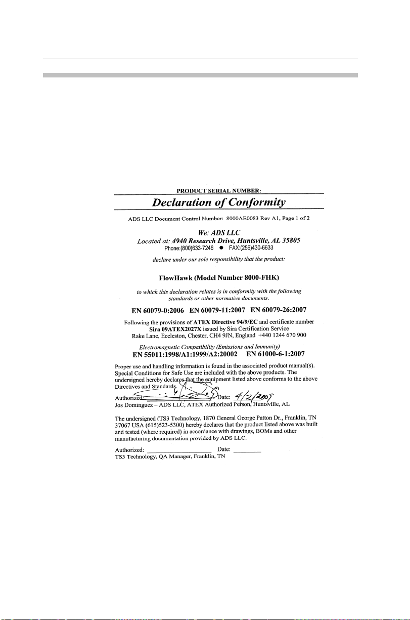
Declaration of Conf ormity
For European (EC member country) applications, a Declaration of
Conformity (DoC) is required to be kept on file at the facility
responsible for repair and maintenance of this equipment. A copy
of the relevant DoC is also shipp e d with each prod uct. If you have
any questions about the Declaration of Conformity, contact IETG
Ltd at the addresses given at the end of this chapter.
Introduction 1-23
Sample FlowHawk Declaration of Conformity – Page 1
 Loading...