

ADS Environmental Services QR 775010 A0 User Manual

ADS Environmental Services ADS Spider User Manual
January 2009 QR 775010 A0
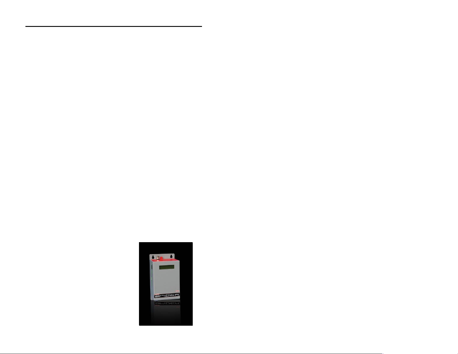
ADS Spider™
User Manual
Compact, Low-Power Telemetry, Logging, and
Alarm System
4940 Research Drive
Huntsville, Alabama 35805
(256) 430-3366
E-mail: supportcenter@adsenv.com
www.adsenv.com

ADS Environmental Services ADS Spider User Manual
© 2009 ADS Environmental Services®. All rights reserved.
ADS® and ADS Environmental Services® are registered trademarks of ADS
Environmental Services.
Spider™ is a trademark of ADS Environmental Services.
Wavecom™ is a registered trademark of Wavecom S.A. in France and other
countries.
RadioShack® is a registered trademark of RadioShack Corporation.
All other brands and product names are trademarks or registered trademarks
of their respective holders.
Notice of Proprietary Information
The information contained herein represents the latest information available
at the time of publication. ADS Environmental Services reserves the right to
make any changes or modifications to the content of this document, without
notice, to reflect the latest changes to the equipment. No part of this
document may be reproduced in any form without the written consent of ADS
Environmental Services.
Software License and Copyright Notice
All software that is supplied as part of this equipment is protected by
copyright laws and international copyright treaties, as well as other
intellectual property laws and treaties. This software is licensed, not sold, and
is intended for use on this device only.
All title and copyrights in and to the software (including but not limited to any
text, instructions, code, “applets” incorporated into the software, images,
photographs, animations, video, audio and music) are owned by Halytech.
You may not reverse engineer, decompile, or disassemble this software for
any purpose. No part of this software may be copied, reproduced, loaned,
rented, leased, or transmitted in any form or by any means electronic or
mechanical, without the express written permission of Halytech.
i

ADS Environmental Services ADS Spider User Manual
Table of Contents
Warnings and FCC Compliance......................................................................... 4
Hazardous Area Notice.................................................................................. 4
Communications Disclaimer........................................................................... 4
FCC Compliance........................................................................................... 4
FCC Part 15.............................................................................................4
GSM/GPRS Modem Information.................................................................... 5
Product Warranty................................................................................................6
New Product Warranty...................................................................................6
Out-of-Warranty Product Repairs................................................................... 6
Troubleshooting Fee...................................................................................... 6
Shipping ........................................................................................................ 7
Introduction.........................................................................................................8
Typical Applications.......................................................................................8
System Overview................................................................................................10
Components................................................................................................10
Inputs .......................................................................................................... 11
Native Inputs..........................................................................................11
Intelligent Inputs (if installed).................................................................. 13
System Monitors..........................................................................................13
Controls.......................................................................................................13
Alarms......................................................................................................... 14
Text Messaging...................................................................................... 15
E-mailing (if e-mail option is installed)..................................................... 15
Voice Alarming (if voice option is installed).............................................16
Control Activation and Deactivation........................................................16
Alarm Acknowledgement........................................................................ 16
Logger......................................................................................................... 17
Automatic Reports (if installed)...............................................................18
Web Server.................................................................................................. 19
Physical Connections................................................................................... 19
Antenna.................................................................................................. 19
Power..................................................................................................... 21
Controls.................................................................................................. 25
Inputs..................................................................................................... 26
Auxiliary Connectors...............................................................................28
Installing a Spider...............................................................................................30
Setting up a Spider for the First Time................................................................32
Setting Location........................................................................................... 34
Setting Date and Time.................................................................................35
Setting User and Password.......................................................................... 36
Configuring Inputs........................................................................................ 38
Calibrating Analog Inputs (if present)........................................................... 40
2-Point Calibration.................................................................................. 40
Manual Calibration ................................................................................. 41
Page 1

ADS Environmental Services ADS Spider User Manual
Calibrating Counter Inputs (if present).......................................................... 42
Scaling Event and Daily Total Inputs (if present).......................................... 42
Setting Controls........................................................................................... 43
Setting up Alarms........................................................................................ 45
Setting up Network Parameters................................................................... 48
LAN Settings..........................................................................................48
WAN Settings (if Web access is required and/or the e-mail option
is installed)..............................................................................49
LAN........................................................................................................50
GPRS..................................................................................................... 50
Setting up E-mail Parameters (if e-mail option is installed)........................... 52
SMTP Authentication.............................................................................. 54
Network Glossary........................................................................................ 54
Save Settings to Disk................................................................................... 55
Load Settings from Disk............................................................................... 55
Exiting Change Settings Mode..................................................................... 55
Normal Operation................................................................................................57
Front Panel Display ..................................................................................... 57
Communicating with a PC............................................................................ 58
Alarms.................................................................................................... 59
Acknowledging Alarms........................................................................... 60
Inputs..................................................................................................... 60
Controls.................................................................................................. 61
History.................................................................................................... 62
About...................................................................................................... 63
Text Messaging Alarms......................................................................................65
Text Message Commands..................................................................................67
Voice Option (if installed)...................................................................................70
GSM units only............................................................................................70
Calling a Spider (GSM units only)................................................................ 71
Voice Alarm Dialling (GSM units only).......................................................... 71
Advanced Operation...........................................................................................72
Automatic Reports (if installed).................................................................... 72
Spider Power Options.................................................................................. 76
Always-on Operation ................................................................................... 76
Extra Low Power Operation – Modem Scheduling....................................... 77
One Spider Controlling Another Spider Through Text Messaging................ 78
Operation...............................................................................................80
Software Upgrade........................................................................................ 82
Appendix A: ADS Spider Inputs.........................................................................83
Appendix B: Connecting to the ADS Spider......................................................85
Local Connection......................................................................................... 85
IN CASE OF DIFFICULTY...................................................................... 85
Appendix C: Local Network Configuration........................................................ 87
Connecting a PC Directly to an ADS Spider................................................. 87
Automatic IP Address Setting Checklist for Your PC............................... 88
Connecting to an Existing Network.............................................................. 88
Appendix D: Remote Access Configuration and Quick Start Guide................ 91
Remote Access ...........................................................................................91
SIM Installation............................................................................................ 91
Page 2

ADS Environmental Services ADS Spider User Manual
Unit Activation.............................................................................................. 92
Network and Email Setup Screen Configuration .......................................... 92
Remote Access Procedure..........................................................................94
Appendix E: Logged Data Format...................................................................... 96
Appendix F: Filtered Report File Format........................................................... 101
Appendix G: Connection to Mobile Network.....................................................102
SIM Card Insertion and Removal............................................................... 103
To Remove the SIM Card..................................................................... 105
Appendix H: Testing E-mail Connectivity.......................................................... 106
Sending Test e-mails................................................................................. 106
Monitoring Test E-mails............................................................................. 107
Appendix I: SDI-12 Operation (if SDI-12 interface is installed).........................108
SDI-12 Sensor Preparation........................................................................ 108
SDI-12 Physical Connection...................................................................... 108
SDI-12 Input Setup.................................................................................... 110
SDI-12 Transparent Mode ......................................................................... 111
Page 3

ADS Environmental Services ADS Spider User Manual
Warnings and FCC Compliance
Personnel installing and maintaining this equipment should follow all
guidelines presented in this manual concerning installation and
maintenance. Failure to strictly adhere to these guidelines can result
in personal injury and/or damage to the equipment.
Hazardous Area Notice
The ADS Spider and accessories are not designed for use in
hazardous areas. Any use of a Spider in a known, rated (per NEC
Article 500) Explosion Potential area is solely at the risk of the user.
Communications Disclaimer
The ADS Spider uses publicly available land-line telephone or thirdparty GSM/GPRS wireless communication services and, therefore,
cannot control the availability of these services. For applications
where the Spider provides alarms using land-line or wireless
communication, problems at the carrier level can delay or totally
prevent the delivery of alarm messages. If the user has questions
regarding the availability of services in an area or information about
outages/interruptions that may have affected service, the user should
contact the telephone company or wireless provider directly.
FCC Compliance
To comply with the Federal Communications Commission (FCC), and
European regulatory agencies, ADS Environmental Services provides
the following information concerning Spider installation and operation.
FCC Part 15
This equipment has been tested and found to comply with the limits
for a Class A digital device pursuant to Part 15 of the FCC rules.
These limits are designed to provide reasonable protection against
harmful interference in a residential installation. This equipment
Page 4

ADS Environmental Services ADS Spider User Manual
generates, uses, and can radiate radio frequency energy and, if not
installed and used in accordance with the instructions, may cause
harmful interference to radio communications. However, there is no
guarantee that interference will not occur in a particular installation. If
this equipment does cause harmful interference to radio or television
reception (which can be determined by turning the equipment off and
on), you should try to correct the interference by one or more of the
following measures:
Reorient or relocate the radio or television antenna.
Move and/or increase the distance between the device
and the radio or television.
Plug the device in an outlet different than the radio or
television.
If these suggestions do not help, contact the ADS Client Services
Department at supportcenter@adsenv.com or 877-237-9585 or an
experienced radio/television technician.
GSM/GPRS Modem Information
The wireless ADS Spider contains a third party GSM/GPRS modem
manufactured by Wavecom. This modem is a Fastrack Supreme 20,
model number WM20452, FCC ID O9QE2687. Use of products
containing this modem must be aware of the following:
Contains FCC ID: O9QE2687
This device complies with Part 15 of the FCC Rules. Operation is
subject to the following conditions: (1) This device may not cause
harmful interference, and (2) This device must accept any
interference received, including interference that may cause
undesired operation.
NOTE: The ADS power supply/charger (P/N 3800-0165) must be
used when powering the ADS Spider externally to maintain the FCC
certification. Use of any other power supply must be pre-approved by
ADS prior to installation or the ADS Spider product warranty and FCC
certification may become void.
Page 5

ADS Environmental Services ADS Spider User Manual
Product Warranty
This section includes the warranty information for the ADS Spider.
New Product Warranty
All new products supplied by ADS will be free from defects in material
and workmanship for up to one (1) year following the date of
shipment from ADS. During this warranty period, upon satisfactory
proof of a defect, the product may be returned for repair or
replacement, at ADS’ sole option. No returns will be accepted unless
the Owner has prepaid shipping and has received a prior
authorization return number from ADS. Please contact ADS to obtain
an authorization return number. Warranty repairs and replacements
will be performed only by ADS. Any unauthorized repair or
replacement will void this product warranty. Any repair or
replacement will be covered by this new product warranty for ninety
(90) days from the date that such repaired or replaced product is
shipped from ADS. This warranty is available only if the product has
been installed and operated in accordance with the procedures
outlined in the ADS Spider Users Manual. This warranty does not
apply to damage by catastrophes of nature, fire, explosion, acts of
God (including, but not limited to, lightning damage and power
surges), accidents, improper use or service, damage during
transportation, or other similar causes beyond ADS’ control.
Out-of-Warranty Product Repairs
After the new product warranty expires, a product may be returned, at
the owner’s prepaid expense, to ADS for repair. The owner will pay
for all parts and labor associated with the repair. Any repair part will
be covered by the new product warranty for 90 days from the date of
shipment from ADS.
Troubleshooting Fee
ADS will charge a troubleshooting fee if the reported product defect
cannot be found and/or the reported defect is not due to a defect in
materials or workmanship.
Page 6

ADS Environmental Services ADS Spider User Manual
Shipping
All repaired products will be returned via surface transportation
prepaid by ADS. Import duties, fees, taxes, and other related charges
are the responsibility of the owner.
THIS IS THE ONLY WARRANTY FOR ADS PRODUCTS. NO
OTHER WARRANTY IS EXPRESSED OR IMPLIED, INCLUDING
FITNESS FOR A PARTICULAR PURPOSE OR
MERCHANTABILITY. PRODUCT REPAIR OR REPLACEMENT IS
THE ONLY REMEDY. IN NO EVENT WILL ADS BE RESPONSIBLE
FOR ANY DIRECT, INDIRECT, CONSEQUENTIAL, OR SPECIAL
DAMAGES.
Page 7
ADS Environmental Services ADS Spider User Manual
Introduction
The ADS Spider (ADS part number SPIDER-LC-XX) is an integrated
monitoring, control, and alarm system designed for remote, lowpower applications. It can monitor various inputs, control outputs,
generate alarms, and log data. The Spider is a complete system,
including all necessary software and hardware.
A Spider can be accessed either locally via a direct Ethernet cable
connection or remotely via a modem or by sending and receiving text
messages. Setting up and interrogating a Spider simply involves
viewing pages through any standard web browser.
NOTE: Text messaging may be referenced as SMS (Short Message
Service) in this manual. Therefore, for the purposes of this manual,
these terms are interchangeable. While users in the United States
typically refer to this method of communication or technology as text
messaging, the international community more commonly refers to this
as SMS. References to SMS in this manual generally exist only in the
context of the Spider user interface.
The Spider is suitable for use by system integrators and OEM
applications. It is housed within a compact, plastic enclosure that
mounts to a wall for indoor applications. For outdoor installations, the
unit must be mounted inside a suitable weatherproof enclosure
(provided by the user). ADS also offers a single-box, IP68 (NEMA 6)
weatherproof version of the Spider housed in a stainless steel
enclosure (ADS P/N SPIDER-LP-XX).
Typical Applications
Security
Access
Air conditioning
Process Control
Waste Management
Page 8

ADS Environmental Services ADS Spider User Manual
Irrigation
Rural Applications
Environmental Monitoring
Page 9

ADS Environmental Services ADS Spider User Manual
System Overview
Each ADS Spider incorporates an industrial controller, an input/output
interface, a logger, a GSM/GPRS cellular phone modem, and a
battery management system with integrated solar panel / AC charger
support.
The ADS Spider is capable of:
1. Monitoring up to eight (8) user inputs
2. Monitoring up to three (3) system inputs
3. Controlling up to eight (8) relay controls
4. Generating up to eight (8) alarms
5. Sending alarm or status text messages
6. Receiving text message commands
7. Sending e-mails (optional)
8. Synthesized voice alarm dialing and call answering (optional)
9. Logging input, control and alarm activity
10. Sending automatic daily reports via e-mail and FTP
(optional)
11. Being configured locally by the user through a standard web
browser
12. Being configured remotely through Web access (only
available through static IP services offered by AT&T)
Components
The following components comprise the ADS Spider:
Base unit (includes connectors and 120-amp resistors)
Power supply/charger (P/N 3800-0165)
12-volt, 7.2-ampere-hour backup battery (P/N 507568)
Battery cable (P/N 3800-0179)
Ethernet cross-over cable (included with base unit)
Antenna (P/N 507385)
Page 10

ADS Environmental Services ADS Spider User Manual
Inputs
The ADS Spider accepts two different types of inputs – native and
intelligent.
Native inputs allow simple switch, voltage, and current sensors to be
connected directly into the Spider.
Intelligent inputs are available as an option and are used to interface
to intelligent sensors. Currently, the Spider supports SDI-12 intelligent
sensors. Other intelligent sensor types will be supported in later
versions.
Native Inputs
Native inputs are connected to the Spider via two multi-pole
connectors. Each multi-pole connector accepts four inputs. They are
labeled INPUT1 through INPUT8, and each is provided with two
screw terminals. Wire sizes up to AWG 16 may be used. Each input
can be configured by the user for operating in one of the following five
modes:
1. “SWITCH” – switch closure or voltage-free contact.
Switch inputs detect either an active (ON) state or an inactive
(OFF) state. The active state is indicated by shorting the two
terminals together, while the inactive state is indicated by the
terminals that remain open. A switch state must be stable for
a minimum of 5 seconds to be recognized.
NOTE: There is no galvanic isolation between different inputs
or the Spider internal circuitry.
2. “ANALOG”
Analog inputs are used to monitor industrial sensors, such as
voltage, current, temperature, and pressure sensors.
Most common sensor types are supported, including:
0 – 20 mA sensors
4 - 20 mA sensors
Page 11

ADS Environmental Services ADS Spider User Manual
0 - 2.5V sensors
0 – 5V sensors
0 – 10V sensors
NOTE: All analog signals share a common ground.
3. “COUNTER”
Counter inputs ensure the count increments each time the
terminals are shorted. Frequencies up to 10Hz are
supported. The counter will roll-over from 99,999 to 0.
4. “EVENT”
Event inputs are used to record occurrences of pulses. A
pulse is generated by temporarily shorting the input terminals
together. Minimum acceptable pulse width is 100 ms. Event
inputs are suitable for monitoring pulses that occur less
frequently than once every 30 seconds. Each time an event
occurs, the Spider logs the time of its occurrence as well as
the total number of events. The total will roll-over from 99,999
to 0.
NOTE: Battery life will be dramatically reduced if a higher
frequency signal is connected to an event input.
5. “DAILY TOTAL”
Daily total inputs are identical to the “EVENT” inputs
described above, except that the event total counter is reset
to 0 every midnight.
6. “UTILITY METER”
This type of input records the number of pulses in a logging
period. It is typically used to record readings from water,
electricity, and gas meters.
7. “DISABLED”
This mode disables the input. The input is removed from all
reports and menus.
The user can tailor the system by assigning application specific input
names. For example, Input 1 may be called “PUMP 3 OK”.
Page 12

ADS Environmental Services ADS Spider User Manual
All native input types may be logged and/or used to trigger alarms.
Please refer to Appendix A: ADS Spider Inputs on page 83 for a
summary of native input types, their specifications, and typical uses.
Intelligent Inputs (if installed)
Intelligent sensors are connected to Spider auxiliary connectors.
Please refer to Physical Connections beginning on page 19 for
details.
Currently, the Spider supports SDI-12 intelligent inputs, described in
Appendix I: SDI-12 Operation (if SDI-12 interface is installed)on
page 108.
System Monitors
Each Spider is fitted with 3 System Monitors:
1. System Temperature – measures temperature inside the
Spider enclosure
2. Battery Voltage – measures the voltage of an external battery
connected to the battery connector
3. Battery Charger Status – gives the current state of the battery
charger (ON or OFF)
System monitors can be used in the same way as inputs (i.e., they
may be logged and/or used to trigger alarms).
Controls
The ADS Spider provides eight controls on two multi-pole connectors.
Each multi-pole connector accepts four controls. Controls are labeled
CN1 through CN8, and each is provided with two screw terminals
internally connected to a relay. In the inactive state, the two terminals
are open-circuit. Upon activation, the relay switches and the terminals
are shorted together. Controls can be activated manually through an
active alarm and/or a programmable, built-in timer. Each control has
Page 13

ADS Environmental Services ADS Spider User Manual
a dedicated 7-day, 24-hour timer with an unlimited number of userprogrammable schedules.
The user can tailor the system by assigning application-specific
names to the controls. For example, Control 3 may become “VALVE
4 ON”.
Controls can be managed in four ways:
1. By accessing the “Controls” page with a browser and clicking
the ON/OFF buttons
2. By sending control text messages to the unit
3. By programming and enabling the timer
4. By programming alarms to activate or deactivate controls
It is possible to use all four forms of control simultaneously. If a timer
is enabled and a manual control command is received through either
the browser or a text message, the manual control will take priority,
temporarily overriding the timer. The override is automatically
cancelled when the programmed timer state matches the manually
requested state.
Controls driven by an alarm have the highest priority, overriding both
manual control and the timer. Furthermore, if two or more alarms
attempt to drive a control in opposite states, the “OFF” command will
override the “ON” command.
Alarms
The ADS Spider can generate up to 8 alarms.
Upon activation, an alarm can perform any or all of the following:
Send text messages
Send e-mails (if e-mail option installed)
Dial any telephone and communicate the alarm message in a
synthesized voice
Activate and deactivate controls
Each alarm can be programmed with a name, a trigger source, 3
separate text message telephone numbers, 2 e-mail addresses, 3
separate voice numbers, the text of a message, and the control to be
Page 14

ADS Environmental Services ADS Spider User Manual
activated. When the trigger becomes active, the alarm is triggered
and the alarm sequence starts.
Alarms are completely independent from inputs. For example, an
input can trigger more than one alarm, each of which will send its own
special text message to its own special telephone numbers.
Text Messaging
If text messaging is enabled, a text message with the programmed
text will be sent to each telephone number, starting with the first. If
sending is successful, the unit will wait for 30 minutes (see following
note) for the user to acknowledge the alarm sequence.
Acknowledging the sequence stops the sending of text messages.
NOTE: The 30-minute waiting period referenced above for the unit
represents the default time period. The user can designate a period
anywhere between 0 and 60 minutes.
If sending is not successful (e.g., due to network congestion), the text
message will be sent to the same number after 1 minute. Up to three
attempts will be made to each number before proceeding to the next
number.
After the 3rd attempt to the 3rd number (if applicable), the unit will stop
sending text messages and wait indefinitely for the alarm to be reset.
This limits the number of text message transmissions per alarm to 9.
E-mailing (if e-mail option is installed)
If e-mail sending is enabled, an e-mail with the programmed text is
sent simultaneously to up to two addresses. If sending is successful,
no more e-mails are sent. If sending is not successful, up to 2 more
attempts are made at 3-minute intervals.
Page 15

ADS Environmental Services ADS Spider User Manual
Voice Alarming (if voice option is installed)
If voice sending is enabled, the Spider will dial the first voice number.
If the call is answered, the Spider will identify itself and verbally
communicate the alarm message. The recipient can acknowledge the
alarm. Acknowledging the alarm will stop all further text message, email, and voice transmissions.
If the alarm call is neither acknowledged nor answered or the line is
busy, the Spider will call the second voice number after 2 minutes. If
this call is also not acknowledged, not answered or is busy, the
Spider will call the third voice number after 2 minutes.
The whole sequence will be repeated up to 3 times. Please refer to
Voice Option on page 70 for more details on the Spider Voice Option
operation.
Control Activation and Deactivation
Alarms can also be used for intelligent control of various systems. For
example, a tank level can be maintained by monitoring a water level
and by controlling a pump. One alarm is set to trigger when the water
level falls below a low level. This alarm is programmed to activate a
control output, which, in turn, switches on the pump. A second alarm
is set to activate when the water level is above a high level. This
second alarm is programmed to deactivate the same control, which
switches off the pump. Thus, the tank level is automatically kept
between the two levels.
Alarm Acknowledgement
Active alarms can be acknowledged in four different ways:
1. By accessing the “Alarms” page with a browser and clicking
on the active alarm
2. By sending a text message to the Spider
3. (GSM systems only) By acknowledging the alarm with the
phone keypad during a voice call
4. By using the “Auto Acknowledge” feature
Page 16

ADS Environmental Services ADS Spider User Manual
Refer to Acknowledging Alarms on page 60 for more information.
If an alarm is acknowledged, but its trigger source is still in the active
state, a new alarm sequence will NOT commence. Instead, the
Spider first will wait for the trigger source to go inactive.
Logger
The Spider incorporates a high capacity solid-state data logger. The
logger stores data into non-volatile memory, maintaining its contents
in the event of a total power supply failure. All records are date/timestamped to a resolution of one second.
The Spider logs the following:
1. Input changes
2. System monitor changes
3. Control changes
4. Alarm activations and resets
5. Text message transmissions and their outcomes
6. Text message command reception
7. E-mail transmissions and their outcomes (when the e-mail
option is installed)
8. Voice alarm transmissions and their outcomes (when the
voice option is installed)
9. System messages
Switch inputs automatically log an input change. If a switch input is
initially in the “OFF” state, goes “ON” for some time, and then goes
back “OFF”, both state changes are logged.
Event and Daily Total inputs automatically log a single record per
pulse. If an event input is initially in the “OFF” state, then goes “ON”
for some time, and then goes back “OFF”, only a single record is
logged.
Analog input, counter input, and system monitor logging are enabled
by the user.
These inputs are logged using the “SIGNIFICANT CHANGE” logging
method. The user specifies the minimum logging period and the
Page 17

ADS Environmental Services ADS Spider User Manual
minimum change that requires logging. For example, the logging
period may be set to 1 hour and the minimum change to 100. The
input will be checked every hour and logged if it has changed by at
least 100 from the last logged value. (To log the data every hour,
simply set the minimum change to 0.)
While the logging period is shared by all analog inputs, counter
inputs, and system monitors, each input has its own programmable
minimum change setting.
If logging of an analog input, a counter input, or a system monitor is
enabled, it will be logged automatically every midnight. This ensures
that at least one sample is recorded every day, even with slowly
varying inputs.
Utility meter inputs are logged every logging period, regardless of the
amount by which they change. Please refer to Appendix A: ADS
Spider Inputs on page 83 for a summary of input types.
Automatic Reports (if installed)
The ADS Spider can be set up to send periodic reports via e-mail
and/or FTP.
E-mail reports are sent to up to three recipients. FTP reports are sent
to a user-specified FTP server.
Each report is a spreadsheet file containing data logged over the
required period.
The advantage of automatic reports is in the Spider’s ability to
automatically deliver logged data without user intervention.
An automatic report containing all data logged in the current day can
be requested at any time by sending the ‘GET REP’ text message
command to the Spider.
Page 18

ADS Environmental Services ADS Spider User Manual
Web Server
A sophisticated web server is built into every Spider. The web server
allows users to communicate with a Spider using common web
browser functionality locally via Ethernet crossover cable or remotely
via Web access (available only when using AT&T static IP services).
The user can use any computer, regardless of type and operating
system, with a web browser (such as Internet Explorer) to connect to
a Spider. NO SPECIAL SOFTWARE is required.
The web server is used for:
1. Responding to connection requests (via LAN or Web access)
2. Providing password-level security
3. Setting up a Spider for the first time
4. Viewing inputs and system monitors
5. Controlling outputs
6. Viewing and resetting alarms
7. Downloading logged data
8. Performing software upgrades
All operations are performed by accessing simple web pages.
Physical Connections
Antenna
WARNING!! The customer is responsible for providing surge
protection hardware and associated grounding systems to meet
applicable electrical codes. Where antennas are mounted on
rooftops or other elevated locations, ADS strongly recommends
providing surge protection. The ADS warranty does NOT cover
damage to a unit that has not been protected by properly installed
protection devices.
The GSM/GPRS modem in the Spider is a quad-band
(850/900/1800/1900 MHz) modem manufactured by Wavecom S.A.
GSM carriers in the United States use only the 850 and 1900
frequencies. All ADS-supplied antennas are suitable for use with the
Page 19
ADS Environmental Services ADS Spider User Manual
Spider. If a non-ADS antenna is installed, it must be suitable for use
with, at a minimum, the dual band (850/1900 MHz) U.S. frequencies.
It also must have a VSWR (Voltage Standing Wave Ratio) of less
than or equal to 2:1 and be fitted with a female FME-type connector.
Gain cannot exceed 3db.
Two types of quad-band antennas are available from ADS for use
with the Spider: a magnetic mount whip and a low profile “wing”.
Extension cables are also offered in 10-, 25-, and 50- foot lengths.
Always use the minimum cable length to prevent signal loss.
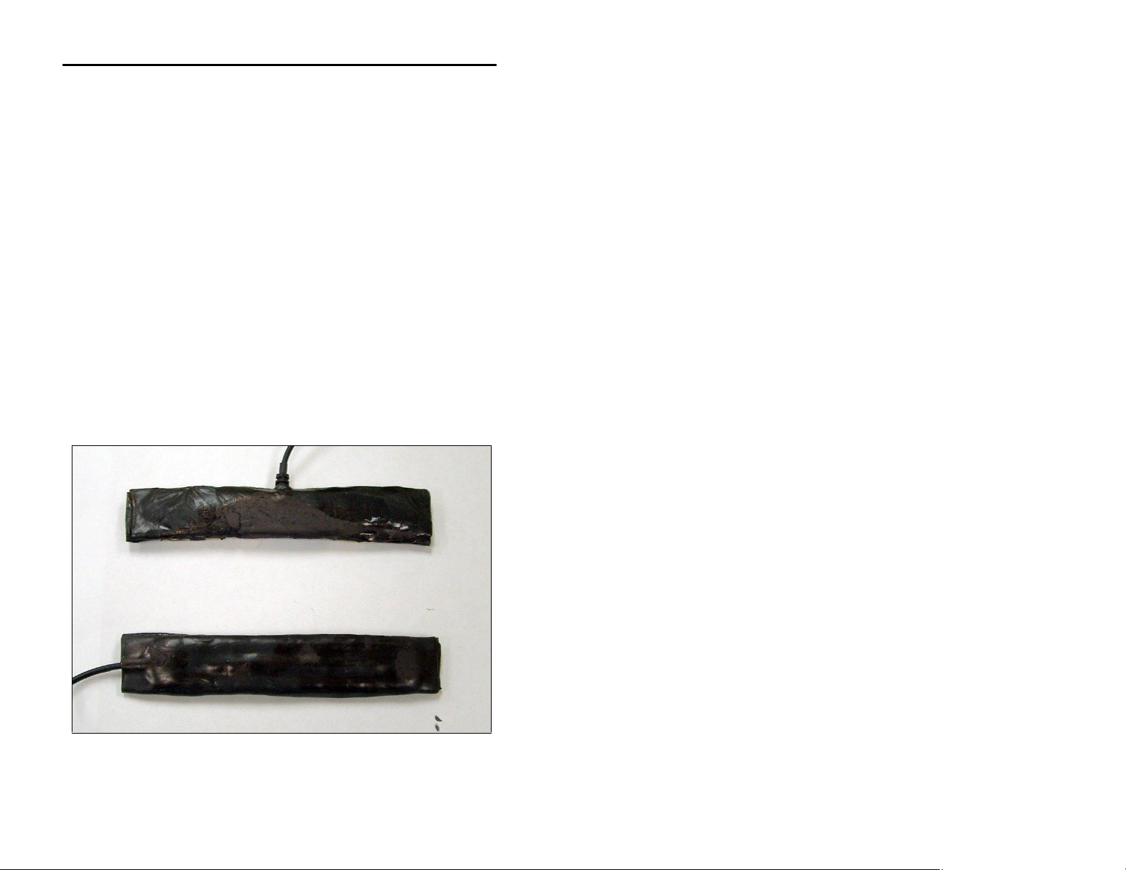
The following image displays the two kinds of direct burial antennas
(P/N 507385) that support the Spider: the wing (top) and the slim
(bottom). The slim antenna is interchangeable with the wing (top)
antenna. The only difference between them exists in the location at
which the cable exits the element. Both antennas can be embedded
directly into road surfaces (and sealed with asphalt) or buried in soil
or most other landscaping materials. They also can be mounted
covertly onto trees, posts, or other structures that provide the most
security and maximum height to ensure the best reception.
Page 20

ADS Environmental Services ADS Spider User Manual
The following table lists the part numbers for the antennas, adapters,
and extension cables:
Part Part Number Comments
Magnetic Mount
Antenna
3800-0128 8-foot cable included,
requires P/N 507482
adapter to fit FME
connector
Wing Antenna 507385 8-foot cable included,
no adapter required
SMA/F to FME/F
507482
Adapter
10’ FME/M to
3800-0166-0
FME/F Extension
Cable
25’ FME/M to
3800-0166-25
FME/F Extension
Cable
50’ FME/M to
3800-0166-50
FME/F Extension
Cable
When attaching the antenna or extension cables, hand-tighten only.
Using tools to tighten antenna connectors may damage them, voiding
the warranty. If connections are outdoors, always seal the connection
completely using rubber or silicone stretch tape or sealing mastic. Do
not crimp or clamp coaxial cables, as any change in circular cable
geometry will result in signal loss and reduced performance.
INSTALLATION WARNING!! When routing antenna cables inside
areas with control equipment, do not lay the Spider antenna cable
close to or parallel with any other cabling! Keep the antenna cable at
least 6 inches away from other conductors, and cross at right angles
only when required. Conduit is not required unless physical
protection is necessary.
Power
The Spider can receive power either from an AC charger with a
backup battery or from a solar panel and backup battery.
Page 21
ADS Environmental Services ADS Spider User Manual
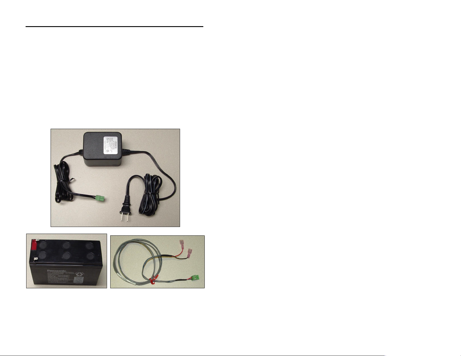
AC Power
AC power comes from an ADS AC power supply/charger (P/N 3800-
0165) that provides a plug for direct connection to the unit. A 12-volt,
7.2-ampere-hour gel cell battery (P/N 507568 and connection cable
P/N 3800-0179) is available for providing backup power in case of a
power outage. Using both sources simultaneously ensures
sustained, uninterrupted power to the Spider under any conditions.
The following images represent the AC charger/power supply (top –
P/N 3800-0165) and the 12-volt battery with cable (bottom – P/Ns
507568/3800-0179):
Page 22
ADS Environmental Services ADS Spider User Manual
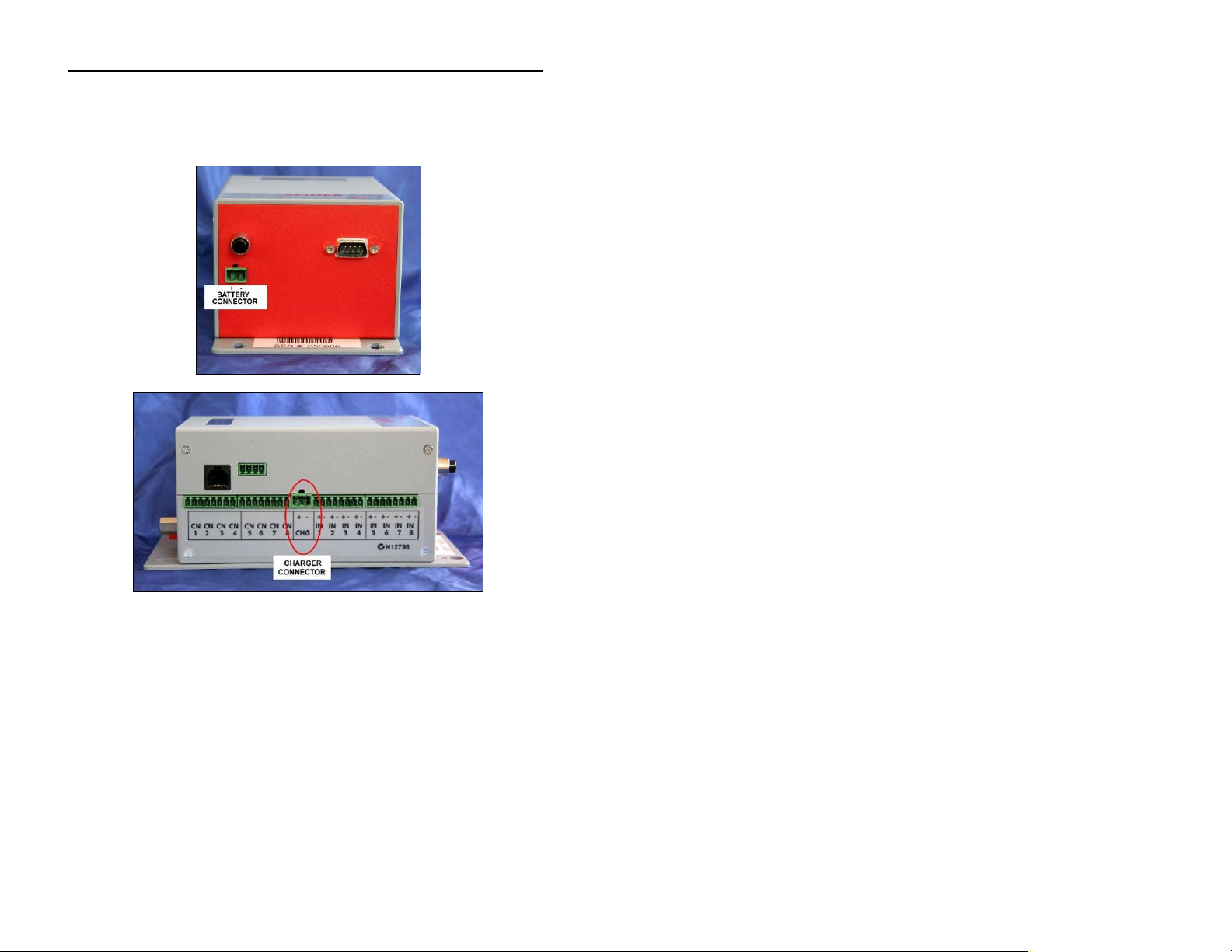
The following images show the locations on the unit for connecting
the charger and the battery:
NOTE: To use a different DC power/charging source (except for
solar), obtain pre-approval from ADS for the alternate power supply
prior to connection. Using any other power supply/charger without
prior approval will void the ADS warranty.
NOTE: The ADS Spider does not have an ON / OFF switch.
Therefore, the unit starts operating when power is applied.
Page 23

ADS Environmental Services ADS Spider User Manual
Charging the Battery
Every Spider incorporates an internal battery management system
supporting 12-volt sealed lead acid batteries with capacities up to 10
ampere hours. It provides all facilities required for a sophisticated
power system, while requiring a minimum number of external
components. Simply connect a battery to the battery connector and a
solar panel or an AC charger to the charger connector. No external
regulator is necessary.
Solar Power
A solar panel, sized by user for the available sun-days, can connect
directly to the CHG port on the Spider. The BATT connector can
accept a rechargeable battery up to 10 ampere hours in size. If the
application requires larger batteries and/or a longer backup capacity,
the user is responsible for sizing and coordinating the appropriate
panel, charging regulator, and battery storage. ADS neither sells nor
supplies these components.
Please observe the correct polarity, as shown on the label next to the
terminal blocks, when connecting batteries and chargers to the
Spider.
Page 24
ADS Environmental Services ADS Spider User Manual
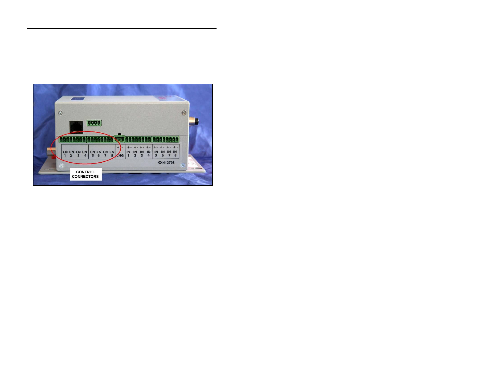
Controls
Controls are connected to terminals marked CN1 to CN8.
Each control provides normally open relay contacts rated to 30 volts,
1 amp resistive loads. External protection diodes must be
installed when driving inductive loads, such as power relays.
A good general-purpose protection diode, also referred to as a
flyback or suppression-type diode, is the 1N4001. This diode is
commonly available from electronics suppliers and consumer
sources, such as RadioShack®.
Connect the diode in parallel with the coil on the power relay.
Connect the cathode (identified by the white stripe on the diode body)
to the positive coil connection and the anode to the negative
connection. This will cause the diode to reverse bias when voltage is
applied to the coil.
Page 25
ADS Environmental Services ADS Spider User Manual
+ -
Switch
Inputs
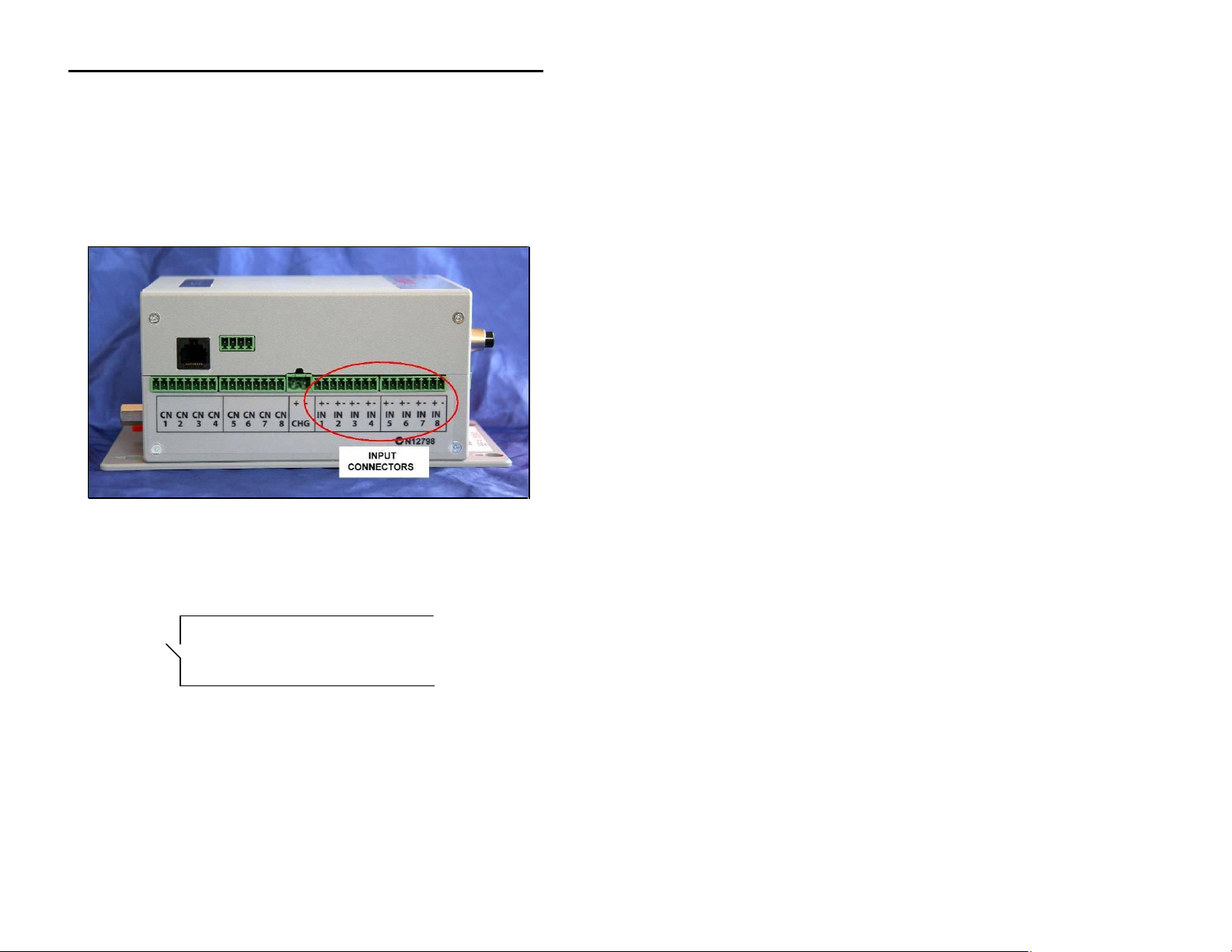
Native Inputs
Native inputs are connected to terminals marked INPUT1 through
INPUT8. Wiring depends on the type of input selected.
1. “SWITCH”, “COUNTER”, “EVENT”, “DAILY TOTAL”, and
“UTILITY METER” types:
Spider system ground
Page 26
Spider
IN X
ADS Environmental Services ADS Spider User Manual
Sensor
+ + -
-
+ -
+ -
+
-
Sensor
+ + -
+ -
+ -
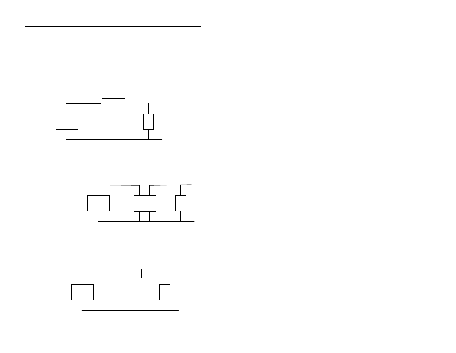
2. “ANALOG” type accepts an analog voltage from 0 – 2.5V.
The following diagrams show wiring details for most common
sensor types.
(i) 2-WIRE 0 - 20 mA and 4 – 20 mA current loop sensors
require an external 120-Ohm, ¼ W resistor (supplied):
Power
Supply
(ii) 4-WIRE 0 - 20 mA and 4 – 20 mA current loop sensors
require an external 120-Ohm, ¼ W resistor
(iii) Voltage inputs may require up to two external resistors:
Power
Supply
Sensor
120-Ohm ¼ W
Resistor
Spider system ground
Spider system ground
Rx
Ry
Spider
IN X
120-Ohm ¼ W
Resistor
Spider IN X
Spider
IN X
Spider system ground
Page 27

ADS Environmental Services ADS Spider User Manual
SENSOR RANGE VALUE OF Rx VALUE OF Ry
0 – 2.5V None required Leave out
0 – 5V 1 Kohm ¼ W metal film 1 Kohm ¼ W
metal film
0 – 10V 3.3 Kohm ¼ W metal
film
1 Kohm ¼ W
metal film
NOTE: You may be able to use the AUX 1 connector to supply the
power to the analog sensor. Please refer to Auxiliary Connectors on
page 28 for more information.
Intelligent Inputs (if installed)
SDI-12: Please refer to Appendix I: SDI-12 Operation on
page 108 for SDI-12 connection and operation details.
Auxiliary Connectors
SPIDER AUXILIARY CONNECTORS
Page 28
 Loading...