

ADS Environmental Services QR 775004 A1 User Manual
ADS® FlowShark® Pulse Operation and Maintenance Manual
March 2009 QR 775004 A1
An introductory guide to the ADS® FlowShark® Pulse Meter
Valid as of Software Revision No. 4.10
1300 Meridian Street, Suite 3000
Huntsville, AL 35801 USA
(256) 430-3366

ii ADS FlowShark Pulse O&M Manual
© 2009 ADS® LLC. All rights reserved.
ADS®, ADS Environmental Services®, and FlowShark® are registered trademarks
of ADS LLC.
NIVUS® is a registered trademark of NIVUS GmbH.
Java™ is a trademark of Sun Microsystems, Inc.
All other brand and product names are trademarks or registered trademarks of their
respective holders.
Notice of Proprietary Information
The information contained herein represents the latest information available at the
time of publication. ADS LLC reserves the right to make any changes or
modifications to the content of this document, without notice, to reflect the latest
changes to the equipment. No part of this document may be reproduced in any form
without the written consent of ADS LLC.

Table of Contents iii
Table of Contents
Chapter 1 Warrant y and Certifications 1-1
Declaration of Conformity ................................................................................... 1-2
Product Warranty ................................................................................................. 1-3
New Product Warranty ................................................................................... 1-3
Out of Warranty Product Repairs ................................................................... 1-3
Troubleshooting Fee ...................................................................................... 1-3
Shipping ......................................................................................................... 1-3
Ex-Approval Transmitter ..................................................................................... 1-5
Ex-Approval Sensors ......................................................................................... 1-10
Chapter 2 Use and Specifications 2-1
Use in Accordance with the Requirements .......................................................... 2-2
Specifications ....................................................................................................... 2-4
Transmitter ..................................................................................................... 2-4
Combi Sensor/Pipe Insertion Sensor ............................................................. 2-5
Air-Ultrasonic Sensor .................................................................................... 2-7
Accessories (Option) ...................................................................................... 2-8
Chapter 3 Safety and Identification 3-1
Device Identification ............................................................................................ 3-2
Replacement Parts and Accessories ..................................................................... 3-3
Emergency and Safety Procedures ....................................................................... 3-4
User’s Responsibilities......................................................................................... 3-5
Chapter 4 System Overview and Operation 4-1
Combination Sensor ............................................................................................. 4-2
Water-Ultrasonic Depth Measurement .......................................................... 4-2
Pressure Depth Measurement......................................................................... 4-3
Flow Velocity Measurement .......................................................................... 4-3
Air-Ultrasonic Depth Sensor ................................................................................ 4-6
Pipe Insertion Sensor ........................................................................................... 4-7
Device Versions ................................................................................................... 4-8
Transmitter ..................................................................................................... 4-8
Sensors ........................................................................................................... 4-9

iv ADS FlowShark Pulse O&M Manual
Chapter 5 Delivery, Maintenance, and Handling 5-1
Delivery and Receipt ............................................................................................ 5-2
Maintenance ......................................................................................................... 5-3
Handling ............................................................................................................... 5-5
Storage ........................................................................................................... 5-5
Transport ........................................................................................................ 5-5
Disposal.......................................................................................................... 5-5
Chapter 6 Installation 6-1
Transmitter Installation and Connection .............................................................. 6-2
General ........................................................................................................... 6-2
Enclosure Dimensions ................................................................................... 6-3
Transmitter Connection ................................................................................. 6-3
Sensor Installation and Connection...................................................................... 6-6
Choosing a Suitable Location for Sensor Installation .................................... 6-6
Sensor Installation ........................................................................................ 6-10
Sensor Connection ....................................................................................... 6-17
FlowShark Pulse Power Supply ......................................................................... 6-25
Overvoltage Protection Precautions ................................................................... 6-27
Regulator Mode ................................................................................................. 6-30
General ......................................................................................................... 6-30
Setting up the Measurement Location ......................................................... 6-31
Connection ................................................................................................... 6-34
Control Algorithm ........................................................................................ 6-34
Communication .................................................................................................. 6-36
General ......................................................................................................... 6-36
Data Communication ................................................................................... 6-36
Communication Options .............................................................................. 6-36
Chapter 7 Initial Startup and Communication 7-1
Establishing Communication Through a Browser ............................................... 7-2
Operator Keypad .................................................................................................. 7-6
Display ................................................................................................................. 7-7
Operation Basics .................................................................................................. 7-8

Table of Contents v
Chapter 8 Parameter Settings 8-1
Quick Start Guide for Setting Parameters ............................................................ 8-2
Basics for Setting Parameters .............................................................................. 8-3
Operation Mode (RUN) ....................................................................................... 8-5
Display Menu (EXTRA) ...................................................................................... 8-9
Parameter Menu (PAR) ...................................................................................... 8-12
Parameter Menu: Measurement Place .......................................................... 8-12
Parameter Menu: Level ................................................................................ 8-19
Parameter Menu: Flow Velocity .................................................................. 8-24
Parameter Menu: Analog Inputs .................................................................. 8-28
Parameter Menu: Digital Inputs ................................................................... 8-30
Parameter Menu: Analog Outputs................................................................ 8-32
Parameter Menu: Digital Outputs ................................................................ 8-35
Parameter Menu: Flow Controller ............................................................... 8-38
Parameter Menu: Settings ............................................................................ 8-47
Parameter Menu: Memory Mode ................................................................. 8-49
Data Structure on the Memory Card ............................................................ 8-53
Parameter Menu: Communication ............................................................... 8-54
Signal Input/Output Menu (I/O)......................................................................... 8-58
I/O Menu: Analog Inputs ............................................................................. 8-58
I/O Menu: Digital Inputs .............................................................................. 8-59
I/O Menu: Analog Outputs .......................................................................... 8-59
I/O Menu: Relay Outputs ............................................................................. 8-60
I/O Menu: Sensors ....................................................................................... 8-60
I/O Menu: Interfaces .................................................................................... 8-63
I/O Menu: Controller ................................................................................... 8-63
I/O Menu: Memory Card ............................................................................. 8-64
Calibration and Calculation Menu (CAL) ......................................................... 8-67
CAL Menu: Level ........................................................................................ 8-67
CAL Menu: Velocity.................................................................................... 8-69
CAL Menu: Simulation ................................................................................ 8-73
Chapter 9 Parameter Tree 9-1
Chapter 10 Data Collection 10-1
Data Collection .................................................................................................. 10-2
Deleting Data Files............................................................................................. 10-4
Viewing Data ..................................................................................................... 10-5

vi ADS FlowShark Pul se O&M Manual
Chapter 11 Troubleshooting 11-1
Chapter 12 Materials and Chemical Resistance 12-1
Chemical Resistance Legend ............................................................................. 12-3
Resistance .................................................................................................... 12-3
Material Names ............................................................................................ 12-3

C H A P T E R 1
Warranty and Certifications
This chapter includes the Declaration of Conformity, the ADS® warranty, and all
required certifications for the ADS FlowShark
®
Pulse.
Please notice that the certifications included in this chapter identify
the FlowShark Pulse as the OCM Pro CF. The FlowShark Pulse is
®
a version of the NIVUS
ADS. In all aspects related to certification, the FlowShark Pulse is
OCM Pro CF designed specifically for
identical to the OCM Pro CF.

1-2 ADS FlowShark Pulse O&M Manual
Declaration of Conformity
EC Declaration of Conformity
Pursuant to
z the EC Low Voltage Directive 73/23/EEC, Annex III
z the EC EMC Directive 89/336/EEC, Annex I and II
z the EC Directive 94/9/EC: Equipment and protective systems intended for use
in potentially explosive atmospheres (ATEX)
We hereby declare that the design of the
Description: Measuring device OCM Pro with active sensor
as delivered complies with the above regulations and following EC directives and
DIN EN standards:
Directive/
Standard
73/23/ EC EC Low Voltage Directive
EN 61010-1 Safety requirements for electrical equipment for measurement,
control and laboratory use – Part 1: General requirements
89/336/EC EC EMC Directive
EN 61000-6-2 Electromagnetic compatibility – Generic immunity standard – Industrial
environment
EN 61000-6-4 Electromagnetic compatibility – Generic immunity standard – Industrial
environment
Title
94/9/EC
(ATEX 100a)
EN 1127-1 Explosive atmospheres – Explosion prevention and protection –
EN 50014 Electrical apparatus for potentially explosive atmospheres – General
EN 50020 Electrical apparatus for potentially explosive atmospheres – Intrinsic
EC Directive: Equipment and protective systems intended for use in
potentially explosive atmospheres
Part 1: Basic concepts and methodology
requirements
safety "i"
Unauthorized changes to the device invalidate this declaration.
Eppingen, March 15
th
, 2007 ..............................................
Heinz Ritz
Head of Quality Management

Product Warranty
This section includes warranty information for the ADS FlowShark Pulse.
New Product Warranty
All new products manufactured by ADS will be free from defects in material and
workmanship for up to two (2) years following the date of shipment from ADS.
During this warranty period, upon satisfactory proof of a defect, the product may be
returned for repair or replacement, at ADS’s sole option. No returns will be accepted
unless the Owner has prepaid shipping and has received a prior authorization return
number from ADS. Please contact ADS to obtain an authorization return number.
Warranty repairs and replacements will be performed only by ADS. Any
unauthorized repair or replacement will void this product warranty. Any repair or
replacement will be covered by this new product warranty for ninety (90) days from
the date that such repaired or replaced product is shipped from ADS. This warranty
is available only if the product has been setup and operated in accordance with the
procedures outlined in the ADS Operations and Maintenance Manual. This warranty
does not apply to damage by catastrophes of nature, fire, explosion, acts of God
(including, but not limited to, lightning damage and power surges), accidents,
improper use or service, damage during transportation, or other similar causes beyond
ADS’s control.
Warranty and Certifications 1-3
Out of Warranty Product Repairs
After the new product warranty expires, a product may be returned, at the owner’s
prepaid expense, to ADS for repair. The owner will pay for all parts and labor
associated with the repair. Any repair part will be covered by the new product
warranty for 90 days from the date of shipment from ADS.
Troubleshooting Fee
ADS will charge a troubleshooting fee if the reported product defect cannot be found
and/or the reported defect is not due to a defect in materials or workmanship.
Shipping
All repaired products will be returned via surface transportation prepaid by ADS.
Import duties, fees, taxes, and other related charges are the responsibility of the
owner.

1-4 ADS FlowShark Pulse O&M Manual
THIS IS THE ONLY WARRANTY FOR ADS PRODUCTS. NO OTHER
WARRANTY IS EXPRESSED OR IMPLIED, INCLUDING FITNESS FOR A
PARTICULAR PURPOSE OR MERCHANTABILITY. PRODUCT REPAIR
OR REPLACEMENT IS THE ONLY REMEDY. IN NO EVENT WILL ADS
BE RESPONSIBLE FOR ANY DIRECT, INDIRECT, CONSEQUENTIAL, OR
SPECIAL DAMAGES.
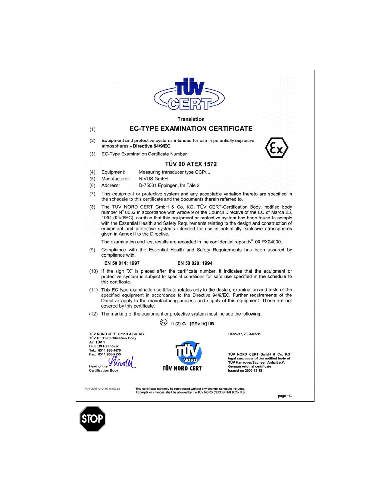
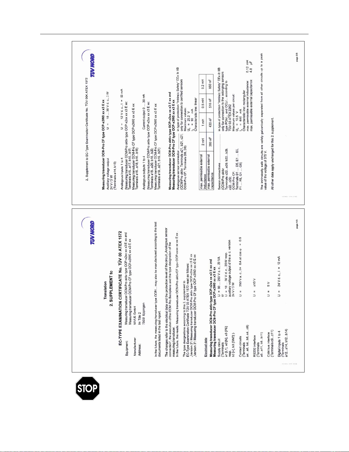
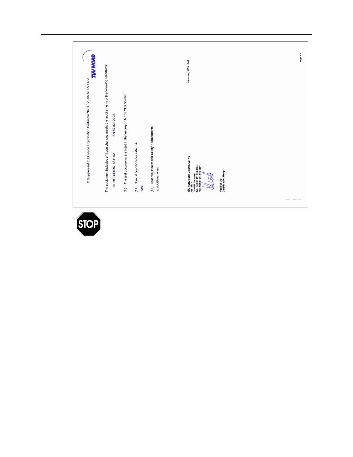
Ex-Approval Transmitter
Warranty and Certifications 1-5
The approval is valid only when the corresponding indicator
displays on the transmitter nameplate.
1-6 ADS FlowShark Pulse O&M Manual
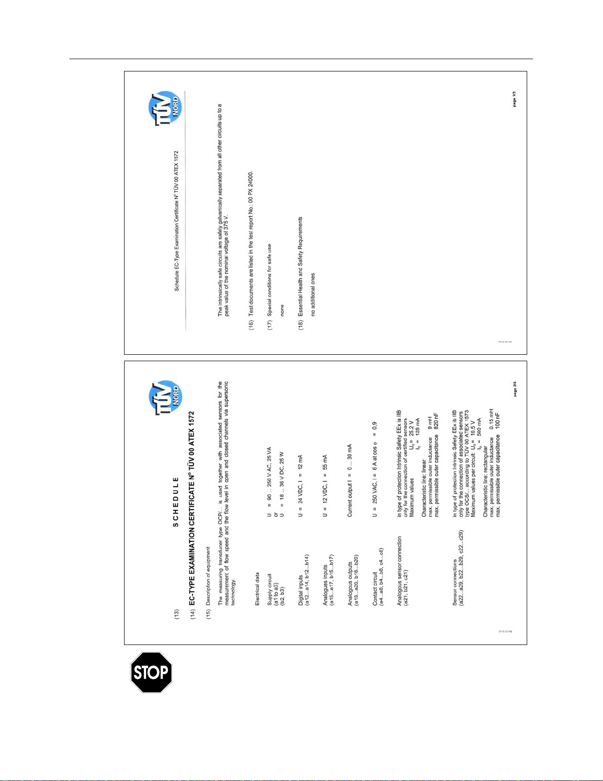
The approval is valid only when the corresponding indicator displays
on the transmitter nameplate.
Warranty and Certifications 1-7
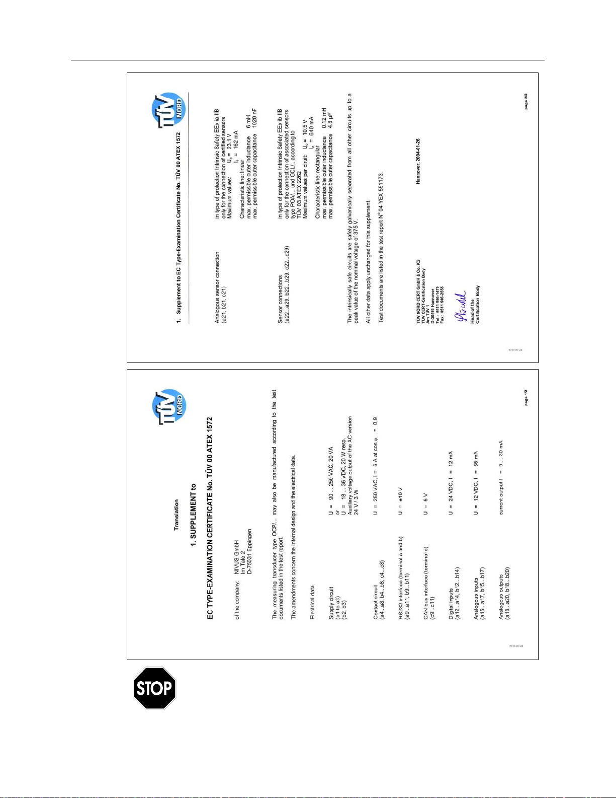
The approval is valid only when the corresponding indicator displays
on the transmitter nameplate.
1-8 ADS FlowShark Pulse O&M Manual
The approval is valid only when the corresponding indicator displays
on the transmitter nameplate.
Warranty and Certifications 1-9
The approval is valid only when the corresponding indicator displays
on the transmitter nameplate.
1-10 ADS FlowShark Pulse O&M Manual
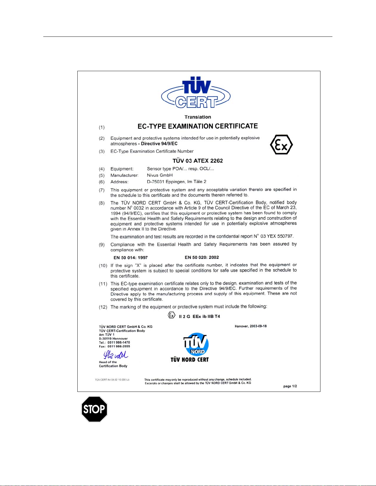
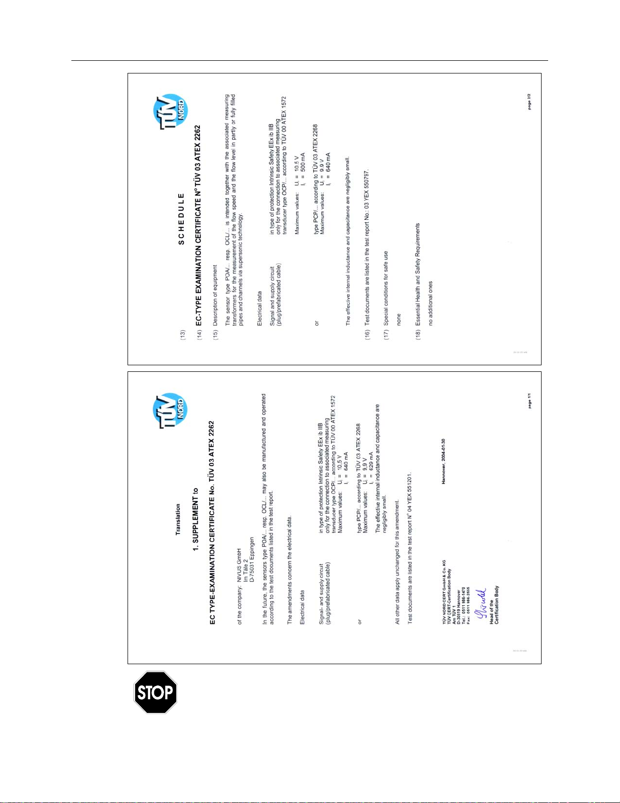
Ex-Approval Sensors
The approval is valid only when the corresponding indicator
displays on the transmitter nameplate.
Warranty and Certifications 1-11
The approval is valid only when the corresponding indicator displays
on the transmitter nameplate.
C H A P T E R 2
Use and Specifications
Please read this instruction manual thoroughly. It contains all the information
necessary to configure and operate the FlowShark Pulse for proper operation. This
manual is written primarily for qualified technical staff that have adequate knowledge
of measurement technology, automation technology, information technology, and
wastewater hydraulics. Reading and following the instructions in this manual before
initial start-up will help ensure success in device configuration. Do not initiate startup until installation is verified and complete.
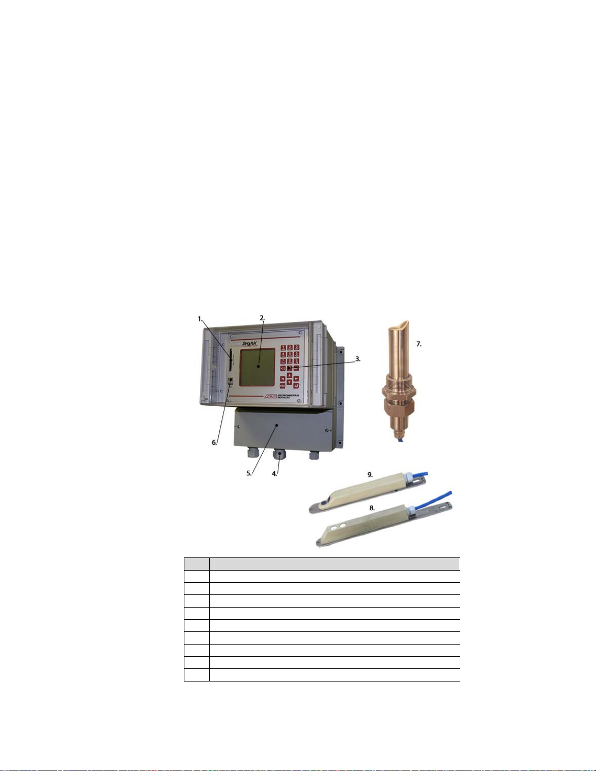
Part Description
1 Memory Card Slot
2 Display
3 Keypad
4 Cable Glands
5 Terminal Clamp Housing
6 USB Interface
7 Pipe Insertion Sensor
8 Air-Ultrasonic Sensor
9 Combi Sensor (Flow Velocity, Water Ultrasonic, and Pressure Depth)
Figure 2-1 Overview
2-2 ADS FlowShark Pulse O&M Manual
Use in Accordance with the Requirements
The ADS FlowShark Pulse and corresponding sensors are designed for measuring
slightly- to heavily-polluted flow in partially-filled and full pipes or other similar
applications. Please adhere to the measurement specifications designated in this
chapter. Monitoring flow under conditions falling outside the documented
specifications of the equipments’ capabilities without prior written permission of
ADS occurs at the owner’s risk.
Modifying or using this equipment for purposes other than the
intended use (described above) without the prior written consent of
the manufacturer will be considered outside the specifications of
the equipment. Therefore, any resulting damages that may occur
will be at the user’s risk or expense.
This equipment has an estimated lifetime of 10 years. Therefore,
inspect and overhaul equipment exceeding 10 years in age.
Ex-Protection
The Ex-version of the FlowShark Pulse active sensor is designed for use in explosive
environments (zone 1).
Always install the transmitter outside Ex-zones!
Approval
Sensor:
Transmitter:
II 2 G EEx ib IIB T4
II(2)G [EEx ib] IIB
Electronic Specifications
Analog sensor connections: Ignition protection type intrinsically-safe
EEx ia IIB
Clamps D8, D9 for connecting certified sensors only
Max values:
U
I
= 23.1 V
0
= 162 mA
0
linear characteristic

Use and Specifications 2-3
Max. outer inductivities allowed 2 mH 1 mH 0.5 mH 0.2 mH
Max. outer capacities allowed 380 nF 430 nF 510 nF 660 nF
Sensor connections Ignition protection type intrinsically-safe
EEx ia IIB
Clamps D1...D5, E1...E5 for connection of accompanying sensors only
F1...F5, G1...G5 Type POA/...OCL/... according to TÜV 03
ATEX 2262
Max. values per circuit:
U
I
= 10.5 V
0
= 640 mA
0
rectangular characteristic
Max. outer inductivities allowed: 0.12 mH
Max. outer capacities allowed: 4.8 µF
The intrinsically-safe circuits are isolated galvanically safe from the remaining
circuits up to a peak voltage of 375 volts.
The certification is valid only when the corresponding label exists
on the transmitter or sensor nameplate.
For installation and initial start-up, perform all work in
accordance with the appropriate certificates of conformity and
testing from the respective authorities.

2-4 ADS FlowShark Pulse O&M Manual
Specifications
Transmitter
Power Supply
Power
Consumption
Wall-Mount
Enclosure
Ex-Approval
(optional)
Operating
Temperature
Storage
Temperature
Maximum
Humidity
Display
Operation
Inputs
100 to 240 V AC, +10% /-15%, 47 to 63 Hz
or 24 V DC ± 15%, 5% residual fluctuation
Maximum 20 VA
• Material: Polycarbonate
• Weight: approximately 6.4 pounds
• Protection: IP65
II(2)G [EEx ib] IIB
-4° to 122° F (-20° to +50° C)
-4° to 158° F (-20° to +70° C)
80%, non-condensing
Back-lit graphic display, 128- x 128-pixel
18 keys, menu-driven in English, German, French, and Italian
• 1 x 4 – 20 mA for external depth measurement (2-wire sensor)
• 1 x RxTx-Bus for ADS air-ultrasonic sensor (Type LUS)
Outputs
Data Storage
Data
Transmission
• 1 (Model 10 transmitter) or 4 (Model 20 transmitter) x 0/4 – 20
mA, 12-bit resolution for external depth measurement, external
setpoints, and data storage setpoint
• 4 digital inputs (Model 20 only)
• 1 (Model 10) or 2/3 (Model 20) velocity sensors connectable
• 1 (Model 10) or 4 (Model 20) x 0/4 – 20 mA, load 500 Ohm, 12-bit
resolution, accuracy greater than 0.1%
• 2 (Model 10) or 5 (Model 20) switchable relays, loadable up to
230V AC / 2 A (cos ϕ0.9)
• RJ45 for Internet communication
Plug-in Compact Flash Card up to 128 MB
Via Compact Flash Card; open protocol via RS 485; direct connection
over a TCP/IP network, internal ISDN, or external GSM/GPRS
gateway

Combi Sensor/Pipe Insertion Sensor
Use and Specifications 2-5
Measurement
Principle
Measurement
Frequency
Protection Rating
Ex-Approval
(optional)
Operating
Temperature
Storage
Temperature
Operating
Pressure
Cable Length
Cable Types
• Ultrasonic transit time (depth measurement) – Combi Sensor
only
• Piezoresistive pressure measurement (depth measurement) –
Combi sensor only
• Correlation with digital pattern detection (flow velocity)
1 MHz
IP 68
II 2 G EEx ib IIB T4
-4° to 122° F (-20° to +50° C) (104° F (40° C) in Ex Zone 1)
-22° to 158° F (-30° to +70° C)
Maximum 58 psi (4 bar) (combi sensor with pressure element
maximum 14 psi (1 bar))
33/66/99/165 feet (10/20/30/50 m), extendable up to 820 feet (250
m); sensors with pressure measurement require pressure
compensation element junction box
• Sensors with pressure measurement:
Outside Cable
Diameter
Sensor Types
LiYC11Y 2x1.5 + 1x2x0.34 + PA 1.5/2.5
• Sensors without pressure measurement:
LiYC11Y 2x1.5 + 1x2x0.34
• Sensors with pressure measurement:
0.34 ±0.01 inches (8.7 ±0.25 mm)
• Sensors without pressure measurement:
0.3 ±0.01 inches (7.6 ±0.25 mm)
• Flow velocity sensor with velocity measurement using cross-
correlation and temperature measurement to compensate for the
effect of temperature on the velocity of sound
• Combi sensor with flow velocity sensor using cross-correlation,
depth measurement via water-ultrasonic, and temperature
measurement to compensate for the effect of temperature on the
velocity of sound (combi sensor only)
• Combi sensor with flow velocity sensor using cross-correlation,
depth measurement via pressure, and temperature
measurement to compensate for the effect of temperature on the
velocity of sound (combi sensor only)
• Combi sensor with flow velocity sensor using cross-correlation,

2-6 ADS FlowShark Pulse O&M Manual
depth measurement via water-ultrasonic (and redundant
pressure measurement), and temperature measurement to
compensate for the effect of temperature on the velocity of
sound (combi sensor only)
Types of
Construction
Medium
Contacting
Materials
Measurement
Range
Zero Point Drift
Measurement
Error
Measurement
Range
Zero Point Drift
Measurement
Error
• Wedge sensor for installation on pipe bottom
• Insertion sensor for installation through pipe wall with nozzle and
cutting ring
Polyurethane, stainless steel 1.4571, PPO GF30, PA (combi sensor
only)
Option: Sensor made of PEEK, resistant against chemical
substances, Hastelloy mounting plate, Titanium mounting plate, FEP
coated cable
Depth Measurement – Water-Ultrasonic
0 to 6.56 feet (0 to 200 cm), lowest absolutely measurable depth
0.13 feet (4 cm)
Absolutely stable
Less than ±0.08 inches (±2 mm)
Depth Measurement – Pressure
0 to 11.5 feet (0 to 350 cm)
Maximum 0.75% of final value (32 °F to 122 °F (0 – 50 °C))
0.5% of final value
<
Measurement
Range
Zero Point Drift
Measurement
Error
Measurement
Range
Number of Scan
Layers
Zero point drift
Error Limits
(per scan layer)
Number of
Sensors
Depth Measurement – External Sensor
Based on device
Flow Velocity Measurement
-3.28 to 19.7 feet per second (-100 to +600 cm/s)
16 (maximum)
Absolutely stable zero point
1% of measurement value (v >3.28 feet per second (1 m/s))
<
0.5 % of measurement value 0.2 inches per second (+5 mm/s) (v
<
<3.28 feet per second (1 m/s))
1 to 3 per transmitter

Use and Specifications 2-7
Sonic Beam Angle
Measurement
Range
Measurement
Error
±5 degrees
-4° to 140° F (-20° to +60° C)
±0.5 K
Air-Ultrasonic Sensor
Measurement
Principle
Measurement
Frequency
Protection Rating
Ex-Approval
Operating
Temperature
Ultrasonic transit time
120 kHz
IP68
II 2 G EEx ib IIB T4
-4° to 122° F (-20 to +50° C) (104° F (+40° C) in Ex Zone 1)
Temperature Measurement
Storage
Temperature
Operating Pressure
Cable Length
Cable Type
Outside Cable
Diameter
Type of
Construction
Medium Contacting
Materials
Measurement
Range
Dead Band
Measurement Error
-22° to 158° F (-30° to +70° C)
Maximum 14 psi (1 bar)
33/66/99/165 feet (10/20/30/50 m), extendable up to 820 feet
(250 m) maximum
LiYC11Y 2x1.5 + 1x2x0.34
0.3 ± 0.01 inches (7.6 ±0.25 mm)
Wedge sensor for installation at top of pipe
Polyurethane, stainless steel 1.4571, PPO GF30, PA
Depth Measurement
0 to 6.56 feet (0 to 200 cm)
0.33 feet (10 cm)
less than ±0.2 inches (5 mm)
Temperature Measurement
Measurement
Range
Measurement Error
-4° to 140° F (-20° to +60° C)
±0.5 K

2-8 ADS FlowShark Pulse O&M Manual
Accessories (Option)
Pressure
Compensation
Element
Memory Card
Read-out Adapter
Read-out Uunit
Pipe Mounting
System
For connection of sensors with integrated pressure measurement
cell
SanDisk compact flash card with 128-MB maximum capacity
Adapter for PCMCIA interfaces, primarily for data read-out via laptop
USB interface for PC connection
For temporarily clamping air-ultrasonic or combi sensors in pipes
DN 200 - 800 (~ID 6 – 32 inches)
C H A P T E R 3
Safety and Identification
Following are the descriptions or interpretations for the general safety or danger
symbols corresponding to the special notes referenced throughout this manual.
Represents cautionary information to observe
Represents special notes
Represents information regarding present dangers associated
with electric voltage
Represents special warnings
To avoid accidents, observe the following information, regulations (such as Exregulations), and safety requirements during installation, initial start-up, and
operation of the FlowShark Pulse.
To ensure safety and maintain the product warranty, ADS must perform all operations
that extend beyond the installation, connection, or configuration procedures
designated in this manual for this device.
Due to the wastewater environment in which the transmitter,
sensors, and cables are installed and operate in the field, this
equipment may become coated with potentially dangerous diseases
and germs. Therefore, please take precautionary measures to
protect human health.
3-2 ADS FlowShark Pulse O&M Manual
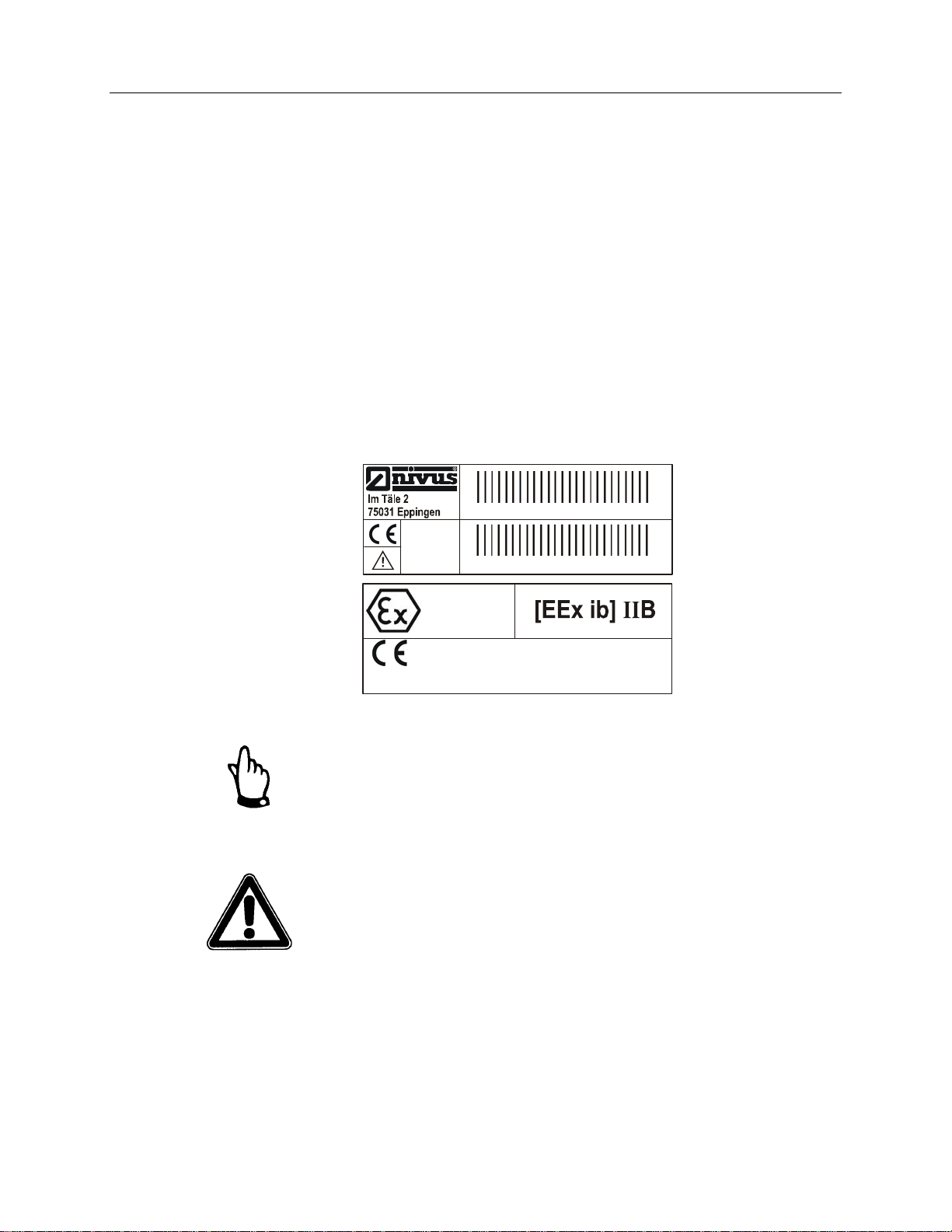
Device Identification
The instructions in this manual pertain only to the FlowShark Pulse. The nameplate
affixed to the bottom of the unit contains the following information:
z Name and address of the manufacturer
z CE label
z Type and serial number
z Year of manufacture
z Ex-label (applies only to Ex-version equipment), as noted in Chapter 2
To expedite processing, please specify the article number and serial number of the
respective transmitter or sensor when inquiring about products or ordering
replacement parts.
100-240V~
20VA
Art. Nr. OCP-x3WO xx x3 E xx
Ser. Nr. JKW xx yyzz
II
(2)G
NR. 0032
TÜV 00 ATEX 1572
Figure 3-1: FlowShark Pulse Nameplate
Elektrische Daten
siehe Bescheinigung
This instruction manual is an essential component of the
FlowShark Pulse; therefore, ADS recommends keeping this manual
accessible at all times.
Please follow all safety instructions contained in this manual.
ADS strictly prohibits disabling or altering the function of the
safety devices in any way.

Replacement Parts and Accessories
ADS does not certify replacement parts or accessories that are not supplied by ADS.
Installing and/or using such products could adversely affect the operation of the
equipment. Therefore, users are responsible for all damages incurred as a result of
using parts or accessories supplied by any manufacturer other than ADS.
Safety and Identification 3-3

3-4 ADS FlowShark Pulse O&M Manual
Emergency and Safety Procedures
In case of an emergency, terminate power in one of the following ways:
z Turn off power at the source from the which the FlowShark Pulse is receiving
power.
z Set the slide switch for power on the FlowShark Pulse to the OFF position.
When performing maintenance, cleaning, and making repairs (authorized personnel
only), disconnect the unit from its power source and take the appropriate measures to
prevent it from powering up accidentally during these activities.

User’s Responsibilities
Obtain all local operating permits required and observe the provisions contained
within the permits. In addition, observe all local laws and regulations concerning the
following:
z Personnel safety (accident prevention regulations)
z Work material and tool safety (safety equipment and maintenance)
z Product disposal (laws on wastes)
z Cleaning (cleansing agents and disposal)
z Environmental protection
Before operating this equipment, all personnel involved in installation and initial
start-up activities must consider and acknowledge all local regulations, such as
performing operations in sanitary sewer environments.
Safety and Identification 3-5
 Loading...