

ADS Environmental Services 4000 530017 A0 User Manual
ADS Model 4000
Installation, Operation, and
Maintenance Manual
December 2004 530017A0
4940 Research Drive
Huntsville, Alabama 35805
(256) 430-3366

ii ADS Model 4000 Manual
2004 ADS
ADS
, ADS Environmental Services, and Accusonic are
Corporation. All rights reserved.
registered trademarks of ADS Corporation.
FieldScan is a trademark of ADS Corporation.
ADS Model 4000
is a trademark of ADS Corporation.
All other brand and product names are trademarks or registered
trademarks of their respective holders.
Notice of Proprietary Information
The information contained herein represents the latest information
available at the time of publication. ADS Corporation reserves the
right to make any changes or modifications to the content of this
document, without notice, to reflect the latest changes to the
equipment. No part of this document may be reproduced in any
form without the written consent of ADS Corporation.

Table of Contents iii
Table of Contents
Chapter 1 Introduction 1-1
Warnings and FCC Compliance..................................... 1-4
FCC Part 68 Compliance ........................................1-4
Product Warranty ........................................................... 1-6
New Product Warranty ........................................... 1-6
Out-of-Warranty Product Repairs........................... 1-7
Troubleshooting Fee ...............................................1-7
Shipping .................................................................. 1-7
Chapter 2 System Overview 2-1
ADS Model 4000 Flow Monitor.................................... 2-3
ADS Model 4000 WR (Wireless-Ready)................ 2-4
Processor Board ...................................................... 2-4
Sensor Interface Boards .......................................... 2-5
Connectors .............................................................. 2-6
Battery Pack ............................................................ 2-6
External Power........................................................ 2-6
Sensors ........................................................................... 2-7
Ultrasonic Depth Sensor ......................................... 2-7
Pressure Depth Sensor ..........................................2-10
Doppler Velocity Sensor....................................... 2-10
Chapter 3 Monitor and Sensor
Installation 3-1
Installing the Sensors in the Pipe ................................... 3-3
Standard Installation ............................................... 3-3
Special Installations .............................................. 3-20
Installing the Monitor in the Manhole ......................... 3-34
Mounting the Monitor to the Manhole Wall......... 3-34
Mounting the Monitor to the Manhole Rim.......... 3-37
Securing the Sensor Cables.......................................... 3-43
Securing the Cables to the Ring (or Band) ........... 3-43
Securing the Cables in the Pipe and Manhole....... 3-44
Connecting the Sensors to the Monitor........................ 3-46

iv ADS Model 4000 Manual
Chapter 4 Communication and
Activation 4-1
Providing Telephone Service ......................................... 4-2
Running the Telephone Cable Between the Monitor
and Service Locations ............................................. 4-2
Mounting the Lightning Protection Module ........... 4-5
Preparing the Telephone Cable............................... 4-5
Wiring the Telephone Cable to the Monitor ........... 4-7
Wiring the Telephone Cable to the Lightning
Protection Module................................................. 4-11
Wiring the Lightning Protection Module to the
Network Interface Box.......................................... 4-13
Using the Direct Modem (DMI) Cable ........................ 4-16
Activating and Confirming the Monitor....................... 4-17
Chapter 5 Maintenance and
Troubleshooting 5-1
Maintaining the System Components ............................ 5-2
Inspecting the Monitor............................................ 5-2
Checking the Sensors.............................................. 5-5
Checking Communication Devices......................... 5-6
Troubleshooting ............................................................. 5-7
General Monitor Problems...................................... 5-8
Ultrasonic Depth Subsystem................................. 5-13
Doppler Velocity Subsystem ................................ 5-18
Pressure Depth Subsystem.................................... 5-20
Appendix A Specifications A-1
ADS 4000/4000WR Flow Monitor...................... A-1
Depth Subsystem ................................................... A-3
Doppler Velocity Subsystem ................................. A-5
Lightning Protection .............................................. A-6

Table of Contents v
Appendix B Switch and Jumper
Settings B-1
ID Switch Settings ..................................................B-2
Options Switch Settings..........................................B-3
Jumper Settings.......................................................B-3
Appendix C External Power C-1

C H A P T E R 1
Introduction
The ADS Model 4000 long-term flow monitor measures open
channel flow in sanitary sewers, storm sewers, pump stations, and
other environments to assist municipalities and other industry in
addressing the following issues:
Planning sewer systems (sizing and rehabilitation)
Reducing infiltration and inflow (I/I)
Monitoring combined sewer overflows (CSOs)
Detecting and monitoring surcharges
1-1
Billing
Monitoring sewage handling facilities (wastewater treatment
plants and pump stations)
The battery-powered, microprocessor-based 4000 monitor displays
exceptional accuracy and reliability in measuring flow depth and
velocity to determine flow rate (quantity) in sewer lines. This flow
data is the essential element required to successfully perform
investigative, analytical, and reporting activities. The 4000 also
supports water quality sampling, event notification, and rain
measurement.
The 4000 monitor uses three flow measurement devices to gather
raw flow data: a quadredundant ultrasonic depth sensor, a pressure
depth sensor, and a Doppler peak velocity sensor. The ultrasonic
and pressure depth sensors apply independent measurement
techniques to collect information used in flow depth calculations.

1-2 ADS Model 4000 Manual
The Doppler velocity sensor gathers peak flow velocity data.
These sensors display exceptional durability and accuracy, even
under harsh and turbulent flow monitoring conditions.
The monitor receives the raw data from the sensors based on a
defined time interval and then processes the data, which may
involve calculating the flow rate. This data, stored in the monitor
memory, is available to the user for collection, further processing,
analysis, and reporting. The reports can assist municipalities and
other industry in planning improvements and additions to sewer
systems, improving the accuracy of billing information, and
providing information for the overall management of sewer
systems.
Special software called FieldScan
and communicate with the monitor for activation, data collection,
confirmation, and diagnostic purposes. Configuration involves
defining the location information file (LIF) for storage in the user's
local directory and building the BASIC code and variables for the
site. The LIF contains information such as pipe characteristics,
monitor identification, selected devices, sensor offsets, data log
rate, and other parameters necessary for measuring the flow both
accurately and efficiently.
enables the user to configure
Note: Refer to the FieldScan User's Guide (#950021**)
for more information.
Activation involves downloading the BASIC code and site-specific
information from the LIF (stored in the user's local directory or
network drive) to the monitor. It also includes initiating monitor
activities such as taking sensor readings, logging flow data,
recording pulses from a rain gauge, sending signals to a sampler,
and managing event notification.
Communication between the monitor and the user’s office or field
computer can occur over a telephone line (remote communication),
cellular digital packet data (CDPD) device (wireless
communication), or direct modem interface (DMI) cable (on-site
communication).
A 4000 monitor specially equipped to receive power from an
external DC power source is available by special order. A

Introduction 1-3
conversion kit also is available to convert existing battery-powered
units to external power.
This manual offers detailed instructions on installing the 4000 flow
monitor and sensors, providing communication with monitor
(remote or on-site), and performing routine maintenance and
troubleshooting on the system.

1-4 ADS Model 4000 Manual
Warnings and FCC Compliance
Manhole and sewer system work involves confined space entry and
is inherently dangerous. Therefore, installers and technicians
should comply with all federal, state, and municipal regulations
concerning confined space entry.
In addition, personnel installing and maintaining this equipment
should follow all guidelines presented in this manual concerning
monitor installation and maintenance. Failure to strictly adhere to
these guidelines can result in personal injury and/or damage to the
monitor.
Note: This monitor does not possess intrinsic safety
certification.
FCC Part 68 Compliance
To comply with the Federal Communications Commission (FCC),
ADS
Corporation provides the following information concerning
4000 flow monitor installation and operation.
This equipment complies with FCC Rules, Part 68. It bears a label
displaying, among other information, the FCC Registration Number
and Ringer Equivalence Number (REN). The user must provide
this information to the telephone company if requested.
The REN identifies the number of devices that may be connected to
the telephone line. Excessive RENs on the telephone line may
prevent devices from ringing in response to an incoming call. In
most areas, the sum of the RENs should not exceed five. To
determine the number of devices you may connect to a line, as
determined by the RENs, contact your telephone company.
This equipment uses threaded-type posts for hardware connection
to the telephone network.

Introduction 1-5
The telephone company may make changes in its facilities,
equipment, operations, or procedures that could affect the operation
of this equipment. If this occurs, the telephone company will
provide advance notice so you can make necessary modifications to
maintain uninterrupted service.
In the unlikely event that this equipment harms the telephone
network, the telephone company will notify you that temporarily
discontinuing telephone service may be required. Notification will
occur in advance of discontinuation, or as soon as practically
possible. They will also inform you of your right to file a
complaint with the FCC if necessary.
This equipment may not be used on public coin phone service
provided by the telephone company. Connection to party line
service is subject to state tariffs.

1-6 ADS Model 4000 Manual
Product Warranty
This section includes the warranty for the ADS Model 4000.
New Product Warranty
All new products manufactured by ADS Environmental Services
will be free from defects in material and workmanship for one year
following the date of shipment from ADS. During this warranty
period, upon satisfactory proof of a defect, the product may be
returned for repair or replacement, at the option of ADS. No
returns will be accepted unless the purchaser has prepaid shipping
and has received a prior authorization return number from ADS.
Please call ADS to obtain your authorization number. Warranty
repairs and replacements will be performed only by ADS or its
authorized representative. Any unauthorized repair or replacement
will void this warranty relative to the product and all of its parts.
Any repair or replacement will be covered by this new product
warranty for 90 days from the date that such repaired or replaced
product is shipped from ADS.
This warranty is available to the original purchaser of the product
and only if it has been installed, operated, and maintained in
accordance with the ADS operations and maintenance manual or as
approved in writing by ADS or its authorized representative. This
warranty does not apply to damage by catastrophes of nature, fire,
explosion, acts of God (including, but not limited to, lightning
damage), accidents, improper use or service, damage during
transportation, or other similar causes beyond ADS’s control.

Out-of-Warranty Product Repairs
After the new product warranty expires, a product may be returned,
at the owner’s prepaid expense, to ADS for repair. The owner will
pay for all parts and labor associated with the repair. Any repair
part will be covered by the new product warranty for 90 days from
the date of shipment from ADS.
Troubleshooting Fee
ADS will charge a troubleshooting fee if the reported product
defect cannot be found and/or the reported defect is not due to a
defect in materials or workmanship.
Shipping
All repaired products will be returned via surface transportation
prepaid by ADS. Import duties, fees, taxes, and other related
charges are the responsibility of the owner.
Introduction 1-7
THIS IS THE ONLY WARRANTY FOR ADS PRODUCTS.
NO OTHER WARRANTY IS EXPRESSED OR IMPLIED,
INCLUDING FITNESS FOR A PARTICULAR PURPOSE OR
MERCHANTABILITY. PRODUCT REPAIR OR
REPLACEMENT IS THE ONLY REMEDY. IN NO EVENT
WILL ADS BE RESPONSIBLE FOR ANY DIRECT,
INDIRECT, CONSEQUENTIAL, OR SPECIAL DAMAGES.
C H A P T E R 2
System Overview
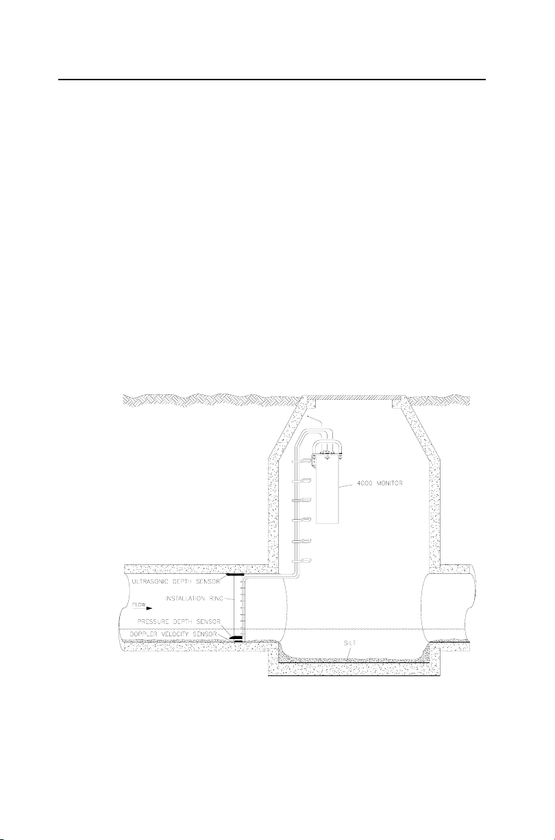
The ADS Model 4000 flow monitor and sensors are primarily
designed for monitoring flow in sanitary and storm sewers. The
monitor mounts to the manhole rim or wall slightly below the
manhole cover; the sensors typically attach to a ring installed in the
sewer pipe a short distance upstream from the manhole invert.
2-1
Typical 4000 flow monitoring system installation

2-2 ADS Model 4000 Manual
The monitor transmits and receives electronic signals to and from
the sensors to measure the flow depth and velocity based on a time
defined interval. It then gathers and processes this information,
which may involve calculating the flow rate. The monitor can
transfer the recorded flow data to the user's PC for determining
flow rate, performing flow analysis, and reporting. These reports
can assist municipalities and industry in planning improvements
and additions to sewer systems, improving the accuracy of billing
information, and providing information for the overall management
of sewer systems.
Special software called FieldScan enables the user to configure and
communicate with the monitor for activation, data collection, and
diagnostic purposes. Configuration involves defining the location
information file (LIF) for storage in the user's local directory and
building the BASIC code and variables for the site. The LIF
contains information such as pipe characteristics, monitor
identification, selected devices, sensor offsets, data log rate, and
other parameters necessary for measuring the flow both accurately
and efficiently.
Activation involves downloading the BASIC code and site-specific
information from the LIF (stored in the user's local directory or
network drive) to the monitor. It also includes initiating monitor
activities such as taking sensor readings, logging flow data,
recording pulses from a rain gauge, sending signals to a sampler,
and managing event notification.
Another software package, Profile, enables the user to process the
flow data, generate graphical and tabular reports, organize data in
the user's local directory, and maintain logs of communication
between the monitor and the user's PC.
Note: Refer to the FieldScan User's Guide (#950021**)
and Profile User's Guide (#950015**) for more
information.
System Overview 2-3
ADS Model 4000 Flow Monitor
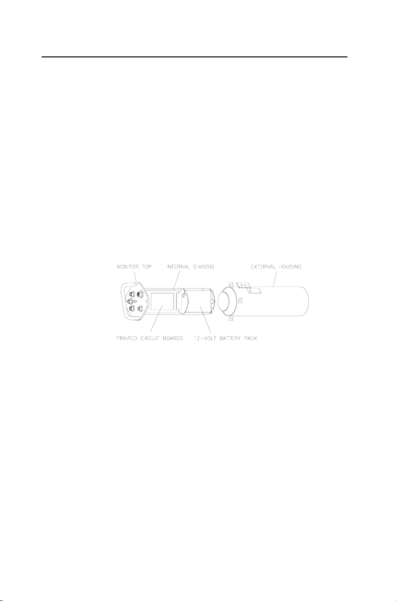
The ADS Model 4000 flow monitor is a waterproof, airtight,
cylindrical, marine-grade aluminum canister housing a chassis
securing multiple printed circuit boards and a portable power
source. The one-piece internal chassis, attached to the inside of the
monitor lid, provides a mounting surface for the following boards:
Central processing unit (CPU) board
Depth interface board
Velocity interface boards
Modem board
Lightning protection board
4000 flow monitor with chassis (left) removed from enclosure (right)
The processor board mounts directly to one side of the chassis. The
velocity boards mount on top of the processor board. The depth
board mounts directly to the other side of the chassis. The modem
board mounts on top of the depth board, and the lightning
protection board mounts below the depth board. A ten-connector
ribbon cable provides an interface among the processing, depth,
and velocity boards.

2-4 ADS Model 4000 Manual
Side view of 4000 flow monitor chassis assembly
ADS Model 4000 WR (Wireless-Ready)
The ADS Model 4000 WR flow monitor is designed to
communicate through an external, wireless communication device.
Wireless communication occurs through a connection between the
monitor and a CDPD device called the ADS Model 3800
.
Note: Since the 4000 WR does not communicate using
telemetry, it contains neither a modem board nor a
lightning protection board.
Processor Board
The processor board contains the central processing unit (CPU).
As the source of all monitor activity, the processor board is
responsible for all of the monitor's high-level functions, including
the following:
Controlling user communication with the monitor
Scanning the sensor interface boards and the rain gauge input
to retrieve and store data

System Overview 2-5
Maintaining the monitor time and date
Performing power management
Providing each board with the parameters required to carry out
the associated operations
Outputting a discrete signal to a sampler
Transmitting the stored and current data to the user's PC
The board allocates portions of memory to firmware (permanently
stored software), data storage, and program manipulation and
calculation. A light-emitting diode (LED) located on the processor
board indicates monitor communication status. The LED
illuminates when the processor board is involved in external
communications. A second LED indicates the processor board's
current level of activity. The light increases in brightness as
processor board activity increases. The board also includes the
monitor clock and a 3-volt lithium backup battery. This battery
maintains the monitor memory during a battery pack swap or power
failure. Battery backed RAM chips provide backup power to the
memory if the 3-volt lithium battery fails.
Sensor Interface Boards
The 4000 flow monitor chassis supports two sensor interface
subsystems:
A velocity subsystem consisting of two boards supporting the
Doppler velocity sensor
A depth subsystem consisting of one board supporting both the
pressure depth sensor and the ultrasonic depth sensor
The sensor interface subsystems communicate with the
corresponding sensors to acquire data, take sensor readings, and
convert raw data to the appropriate engineering units of
measurement.

2-6 ADS Model 4000 Manual
Connectors
Connectors located on top of the monitor receive the following
cabling and components:
Ultrasonic depth sensor
Doppler velocity sensor
Pressure depth sensor
Telemetry or serial (DMI or wireless) communication
Rain gauge/sampler/external power
Battery Pack
The 12-volt battery pack, mounted to the bottom of the chassis,
provides the power for operating the monitor and maintaining the
monitor memory through the power supply on the processor board.
The monitor measures the battery voltage, and the FieldScan and
Profile software applications provide a user-defined setting to
ensure the monitor signals a warning when the available power is
low.
External Power
The 4000 monitor also can receive power from an external DC
power source when equipped with a special conversion kit.
External power requires a power source running between 9 and 14
volts at 1 amp of continuous current.

Sensors
The 4000 flow monitor uses the sensors to gather raw flow data.
The ultrasonic and pressure depth sensors use independent
measurement techniques to collect information concerning the
depth of the flow. The Doppler velocity sensor gathers peak flow
velocity data.
A sewer system's hydraulics are much more stable and uniform in
the incoming pipe than in the manhole invert or outgoing pipe.
Therefore, the sensors mount to a stainless steel expandable ring or
stainless steel bands installed in the pipe upstream from the
manhole. Installing them upstream minimizes hydraulic effects and
erroneous data readings caused by foamy waters, flow waves,
sewer noise, non-laminar flow, and obstructions in the manhole.
The process of installing the sensors in the incoming pipe is
patented by ADS.
Ultrasonic Depth Sensor
System Overview 2-7
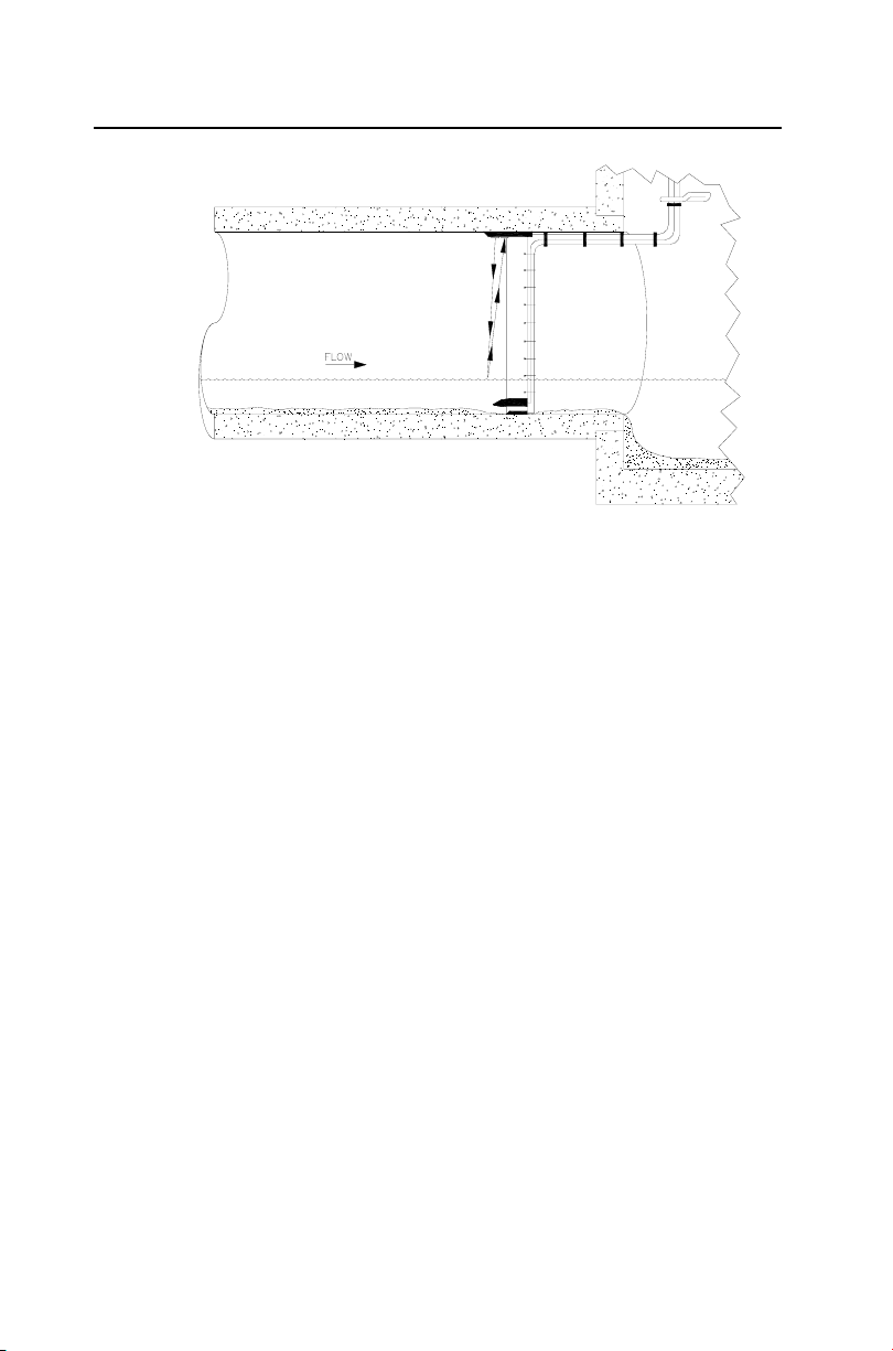
The ultrasonic depth sensor, which mounts at the crown of the pipe,
transmits sound waves from the sensor face to the surface of the
flow. It then measures the time elapsed between transmission and
reception of the sound signal. The distance between the sensor face
and flow surface is the range. Based on the elapsed time and the
speed of sound, the monitor calculates the depth of the flow by
subtracting the range from the pipe diameter. The monitor
compensates for the speed of sound in the air using the temperature
recorded by one of two temperature sensors housed within the
ultrasonic depth sensor.
2-8 ADS Model 4000 Manual
Ultrasonic depth sensor sending signals to flow surface to determine range
Quadredundancy
Each ultrasonic depth sensor contains four ultrasonic transducers.
Taking readings with four transducer pairs gives the sensor
quadredundancy, which ensures greater sensor reading reliability.
To take a reading, one transducer transmits a sound wave while a
second transducer listens for the returning echo. Each transducer
has its own electronic circuitry and dedicated wiring for true
redundancy.
Data Scrubbing
Flow conditions and internal structures introduce many potential
obstacles to obtaining accurate flow data in sewer systems and
manholes. Some of these obstacles may include noise, turbulent or
wavy flow, a foamy flow surface, side connections, rungs, broken
pipes, or drop connections.
To minimize these effects, ADS uses a process of eliminating
erroneous data called data scrubbing. Initial data scrubbing occurs
routinely in the following way as the monitor takes readings:
The monitor fires each sensor and averages the multiple
readings.

System Overview 2-9
The monitor discards the clearly erroneous readings (i.e.,
readings well outside the range of the majority of the
readings).
The monitor records the percentage of all acceptable readings
used to arrive at the average value.
Secondary scrubbing also can occur during data collection from the
monitor to the analyst's PC using the Profile software. Refer to the
Profile User's Guide (950015**) for more information.
Standard Ultrasonic Depth
The standard method for processing ultrasonic depth involves firing
the sensor once to take 32 readings for each of the 4 user-defined
transducer pairs. The monitor discards all false and multiple
echoes and then averages the good readings to arrive at the final
reading for each pair. It then logs each of the 4 pairs.
Smart Depth
The 4000 also includes an enhanced algorithm in the firmware
(permanently stored software), which can be enabled by the user,
for processing ultrasonic depth that automatically filters out bad
signals or erroneous readings due to flow problems or obstructions.
This process produces more accurate data, yields one final depth
measurement, and reduces the amount of stored data. It also
significantly decreases the need for manual analysis and editing.
Each time the monitor fires the sensor to take a reading, the
algorithm triggers two separate processes. First, the algorithm
automatically determines a set of standards, or range window, for
good return echoes. It accomplishes this by digitizing the analog
return signals and firing all 12 transducer pairs 5 times each (60
total firings). Then, an average is taken of the pairs to determine
the range. The range is set by scanning through the digital data and
recording the strongest returning echoes. A range window is
created around these echoes. From that point forward, the monitor
accepts echoes only from within that range and screens out the bad
signals.

2-10 ADS Model 4000 Manual
The second process involves applying the standards set by the
algorithm in the first sensor firing to process the return echoes and
determine the range actually used to record the depth of flow in the
pipe. The monitor takes 32 analog readings for each of the 12
transducer pairs (384 total firings). The analog signals produce a
greater resolution and accuracy. The monitor applies the range
window to each of the 32 readings and then screens out the signals
outside of that window (data scrubbing). It takes intrapair and
interpair averages, applies the scrubbing routine again, and
produces one final range. To conserve memory, the monitor stores
this single range rather than the four ranges used in the standard
design. However, using the smart depth feature consumes battery
life at a higher rate than standard ultrasonic depth.
Pressure Depth Sensor
The pressure depth sensor typically mounts at the bottom of the
pipe. While the ultrasonic depth sensor can only measure depths
up to slightly below full pipe capacity, the pressure depth sensor
can measure depths greater than a full pipe that might extend up
into the manhole (surcharges).
The pressure depth sensor contains a differential pressure
transducer that transmits an output voltage corresponding to the
difference between the water pressure and the air pressure in the
sewer. It measures water pressure through a port on the underside
of the sensor and air pressure using an integral vent tube running to
the top of the manhole. The monitor calculates the depth of the
flow by reading the difference in pressures. The pressure depth
system also compensates for temperature using a temperature
sensor housed within the pressure depth sensor.
Doppler Velocity Sensor
The Doppler velocity sensor mounts at the bottom of the pipe. It
emits a wide, omni-directional sound wave at a specific frequency
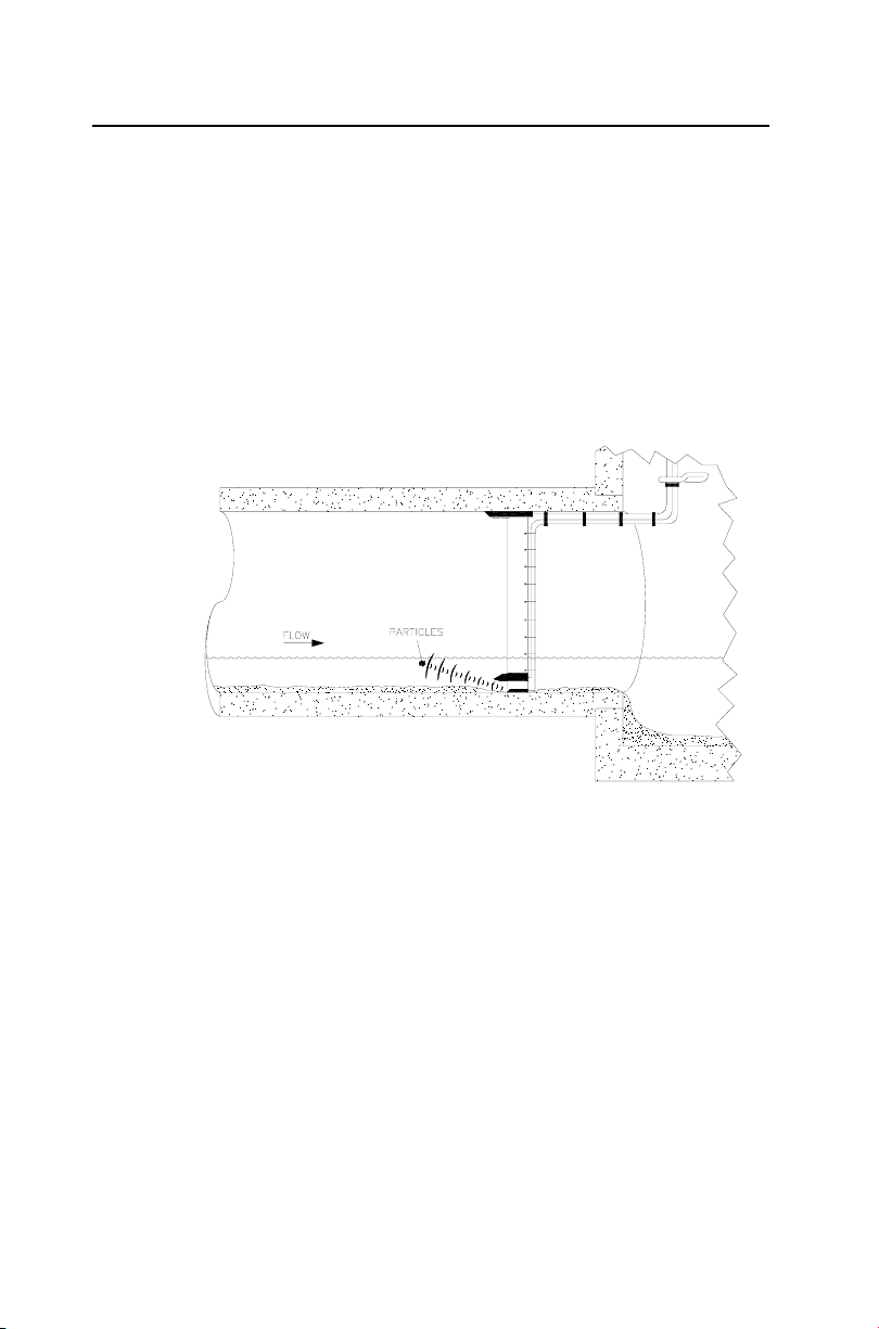
System Overview 2-11
upward into the flow. The sound wave bounces off particles in the
flow and returns to the sensor. The velocity sensor measures the
change in the sound wave's frequency from transmission to
reception. This change is used to determine the velocity of the flow
based on the Doppler effect.
The Doppler effect describes the shift in frequency of a sound wave
emitted by a moving object in relation to a stationary point. In this
case, the moving objects are particles in the flow, the stationary
point is the velocity sensor, and the received signal is the reflection
of the sound wave (emitted by the velocity sensor) off the particles.
Doppler velocity sensor sending signals reflecting off particles in the flow

C H A P T E R 3
Monitor and Sensor Installation
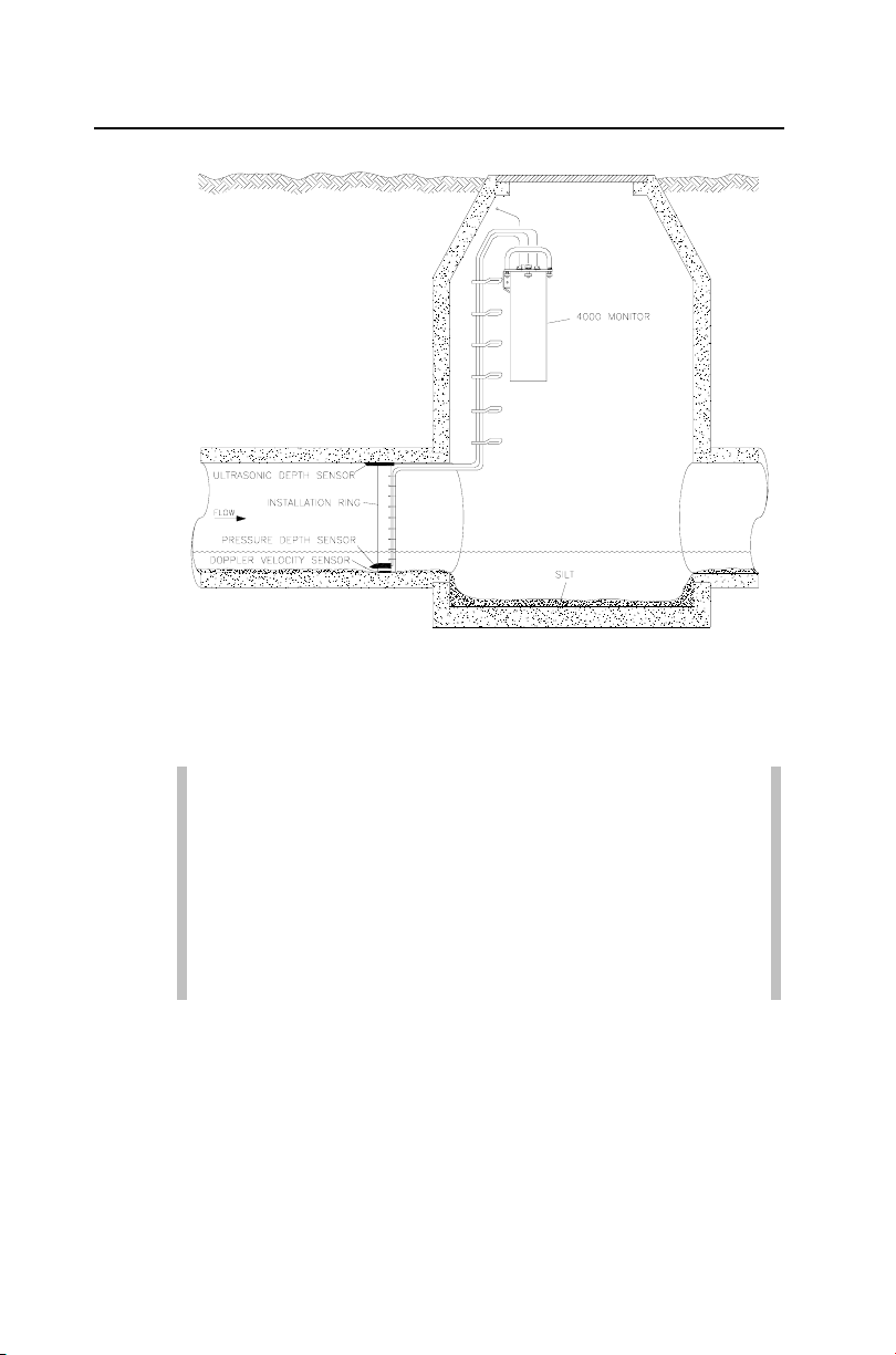
The ADS Model 4000 flow monitor and sensors are primarily
designed for monitoring flow in sanitary and storm sewers. The
monitor mounts to the manhole rim or wall slightly below the
manhole cover.
A sewer system’s hydraulics are much more stable and uniform in
the incoming pipe than in the manhole invert or outgoing pipe.
Therefore, the sensors mount to a stainless steel expandable ring or
stainless steel bands installed in the sewer pipe a short distance
upstream from the manhole invert. Installing the sensors upstream
minimizes the hydraulic effects and erroneous data readings caused
by foamy waters, waves in the flow, sewer noise, non-laminar flow,
and obstructions in the manhole.
3-1
The process of installing the sensors in the incoming pipe is
patented by ADS
.
3-2 ADS Model 4000 Manual
Typical 4000 flow monitor and sensor installation
This chapter contains general instructions for properly installing the
monitor and sensors in sanitary, storm, and combined sewer lines
and manholes.
Note: Manhole and sewer system work involves
confined space entry and is inherently dangerous.
Therefore, installers and technicians must comply with all
federal, state, and municipal regulations concerning
confined space entry. ADS is not responsible for any
injuries, damages, claims, or liability resulting directly or
indirectly from the use of this installation guide or the
installation of any ADS equipment.

Monitor and Sensor Installation 3-3
Installing the Sensors in the Pipe
There are two types of sensor installations:
Standard Installations
Special Installations
Standard Installations involve installing a stainless steel ring to
mount the sensors in round pipes up to 48 inches (122 cm) in
diameter. Special Installations involve installing stainless steel
bands to mount the sensors in round pipes over 48 inches (122 cm)
in diameter or irregular-shaped pipes of any size. This chapter
includes the procedures for performing sensor installations under
either condition and connecting the sensors to the monitor.
Standard Installation
Performing a standard sensor installation involves the following
process:
Gathering the equipment and supplies
Assembling the ring
Mounting the sensors on the ring
Installing the ring in the pipe
Before beginning the installation, conduct a thorough investigation
of hydraulic and other site conditions. The hydraulics of a site
directly affect the monitor's ability to accurately measure flow
depth and velocity. In addition, measure the horizontal and vertical
pipe dimensions carefully. Even slightly inaccurate pipe
dimensions can significantly skew and misrepresent flow data.

3-4 ADS Model 4000 Manual
Gathering Parts and Supplies
Obtain the following supplies before installing the ring and sensors
to prevent any costly delays. When ordering, specify the 4000 flow
monitor ring-mounted installation hardware.
Note: The values and units that appear in italics are
direct conversions; therefore, these mechanical sizes may
not actually exist. ADS has included the conversions only
to enhance readability.
Quantity Unit Description ADS Part
1 each 4000 flow monitor ADS Model 4000
15 each
15 each plastic push mount I01-0006
15 each 11-inch cable tie (28-cm) I05-0003
25 each 4-inch cable tie (10-cm) I05-0001
15 each 8-inch cable tie (20-cm) I05-0002
15 each anchor cable ties I05-0004
1 each stainless steel ring (sized
1 each sliding ultrasonic sensor
1 each stabilizer sliding bracket I25-0002
1 each spreader assembly I10-0003
1 each 18-inch (46-cm) stainless
¼- × 2 ¼-inch stainless
steel anchor bolt
for pipe)
bracket
steel crank handle
Number
I01-0002
I25-00530063
I25-0001
I10-0012
Monitor and Sensor Installation 3-5
Assembling the Ring
The flow sensors mount to a stainless steel ring that is installed in
the pipe. Several different ring sizes exist, and each ring is
adjustable within about 3 inches to fit pipes of different diameters.
Assemble the ring in the following way:
Note: These instructions generally apply to overlapping
rings. However, the 8-, 10-, and 12-inch rings do not have
an overlapping section. Therefore, these non-overlapping
rings will require small modifications to the assembly
process. To assemble a non-overlapping ring, proceed
directly to step 4.
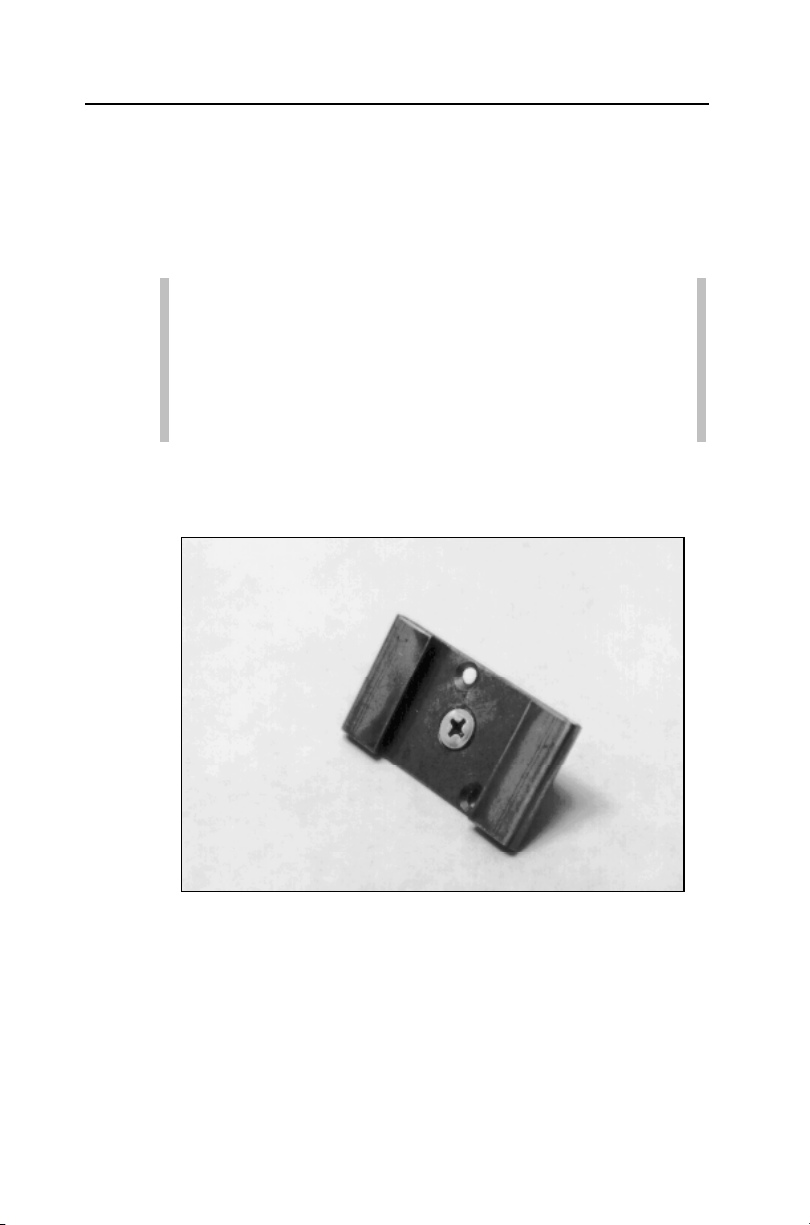
1. Insert the spreader mechanism screw through the hole in the
center of the ring stabilizer. Ensure that the head of the screw
fits into the countersunk hole.
Ring stabilizer with spreader mechanism screw
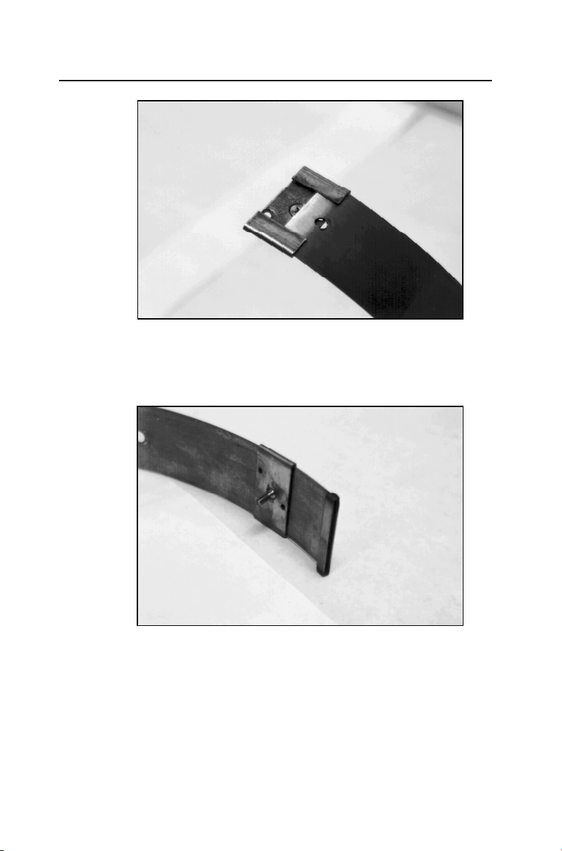
2. Slide the open end of the ring (end without the welded metal
band) through the flanges in the ring stabilizer, making sure
the flanges face the outside of the ring and the spreader
mechanism screw faces the inside of the ring.
3-6 ADS Model 4000 Manual
Sliding the ring stabilizer onto the ring
3. Slide the ring stabilizer all the way around the ring until it is
about 4 inches (10 cm) from the welded metal band at the other
end of the ring.
Moving the ring stabilizer into position
4. Position the ring with the downstream edge (edge with the
holes) facing you.
Monitor and Sensor Installation 3-7
5. Slide the ultrasonic sensor mount onto the open end of the ring
with the back of the ultrasonic mount (side with the slots)
facing the outside of the ring. The side with the backstop
should face the inside of the ring.
Sliding the ultrasonic sensor mount onto the ring
6. Move the ultrasonic sensor mount around the ring.
Note: Steps 7 and 8 apply only to overlapping rings.
Proceed directly to step 9 for non-overlapping rings.
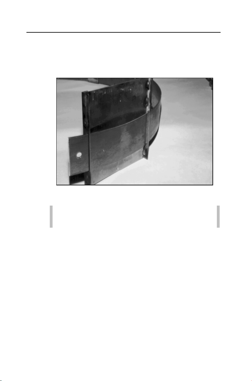
7. Slide the open end of the ring through the slot in the welded
band of the ring until it overlaps about 4 inches (10 cm).
8. Spread the ring sections apart so that you can slide the ring
stabilizer with the spreader mechanism screw into the gap.
 Loading...