

ADS Environmental Services 3600 530002 A2 User Manual
3600 Flow Monitor
Operation and Maintenance Manual
May 1998 530002A2
An introductory guide to the ADS 3600 intrinsically safe flow monitor
ADS Corporation
4940 Research Drive
Huntsville, AL 35805 USA
(256) 430-3366

Copyright 1998 ADS Corporation
ADS and QuadraScan are registered trademarks of ADS Corporation. All other
brand and product names are trademarks or registered trademarks of their respective
holders.
FieldScan
is a trademark of ADS Corporation. All other brand and product names are
trademarks or registered trademarks of their respective holders.
The IBM Personal Computer is a trademark of International Business Machines
Corporation.
Notice of Proprietary Information
The information contained herein represents the latest information available at the time of publication.
ADS Corporation reserves the right to make any changes or modifications to the content of this document,
without notice, to reflect the latest changes to the equipment. No part of this document may be reproduced
in any form without the written consent of ADS Corporation.

Contents
Chapter 1 Introduction 1-1
The ADS Flow Monitoring System .................................................................... 1-3
Intrinsic Safety.................................................................................................... 1-5
Maintenance Restrictions.................................................................................... 1-7
Warnings, Certifications, FCC Compliance, and Conformity............................ 1-8
i
Flow Monitoring with the QS3600............................................................... 1-3
Unique Features ............................................................................................ 1-5
Installation and IS Considerations ................................................................ 1-6
Intrinsically Safe (IS) Certification............................................................... 1-8
FCC Compliance........................................................................................... 1-8
Additional Notice of Canadian Emissions Requirements........................... 1-10
Declaration of Conformity.......................................................................... 1-10
Chapter 2 Hardware 2-1
Major Components of the QS3600 Monitor ....................................................... 2-3
Processor Board ............................................................................................ 2-3
Sensor Interface Boards ................................................................................ 2-5
Flow Sensors................................................................................................. 2-5
Battery Pack.................................................................................................. 2-5
IS Modem and Telephone Interface Box...................................................... 2-6
External Modem Unit ................................................................................... 2-7
Data Access Arrangement........................................................................... 2-10
Chapter 3 Flow Measurement 3-1
Monitor Operation .............................................................................................. 3-2
Monitor Activation ....................................................................................... 3-2
Flow Sensor Measurement Techniques .............................................................. 3-4
Upstream Installation.................................................................................... 3-4
Quadredundancy ........................................................................................... 3-4
Ultrasonic Depth Sensor ............................................................................... 3-4
Pressure Depth Sensor .................................................................................. 3-5
Doppler Velocity Sensor............................................................................... 3-6
Ultrasonic Depth Data Scrubbing ....................................................................... 3-7
Transmitting Data to the Computer .................................................................... 3-8

ii ADS 3600 Flow Monitor O&M Manual
Confirmation....................................................................................................... 3-8
Chapter 4 Ring, Sensor, and Special Installations 4-1
Preparing for Installation .................................................................................... 4-3
Required Supplies ......................................................................................... 4-4
Ring Assembly.................................................................................................... 4-5
Assembling the Ring..................................................................................... 4-5
Connecting the Spreader Mechanism ........................................................... 4-8
Quality Control ........................................................................................... 4-11
Non-Overlapping Rings.............................................................................. 4-12
Mounting the Sensors ....................................................................................... 4-13
Mounting an Ultrasonic Sensor .................................................................. 4-13
Mounting a Doppler Velocity Sensor ......................................................... 4-13
Mounting a Pressure Depth Sensor............................................................. 4-14
Connecting Inputs and Outputs......................................................................... 4-16
Installing the Ring............................................................................................. 4-17
Final Sensor Cable Preparation................................................................... 4-19
Special Installations .......................................................................................... 4-20
Required Supplies ....................................................................................... 4-21
Standard Ultrasonic Mount......................................................................... 4-22
Adjustable Ultrasonic Mount...................................................................... 4-27
Surcharge Mount......................................................................................... 4-30
3/4 Band Velocity Mount ........................................................................... 4-34
1/2 Band Velocity Mount ........................................................................... 4-38
Chapter 5 Monitor Installation and Activation 5-1
Installing the EMU.............................................................................................. 5-2
Pavement Box Location................................................................................ 5-3
Underground Services and Lines Location................................................... 5-3
Pavement Box and Cable Trenching............................................................. 5-4
Pavement Box Installation ............................................................................ 5-5
External Modem Unit (EMU) Installation.................................................... 5-8
Communication Cable Installation ...............................................................5-8
Communication and Telephone Cable Wiring ........................................... 5-12
Direct Connection Communication (SCADA System) .............................. 5-14
Direct Connection Communication (Portable Computer) .......................... 5-15
Baud Rate Setup.......................................................................................... 5-15
Jumper Settings........................................................................................... 5-18
Multiplexor Priority Setting........................................................................ 5-20
Monitor Installation .......................................................................................... 5-22
Telephone Interface Box Installation.......................................................... 5-23

Contents iii
Lightning Protection Module Installation................................................... 5-25
Monitor Activation ........................................................................................... 5-27
Data Collection and Confirmation.................................................................... 5-28
Chapter 6 Monitor Maintenance 6-1
Remote Confidence Checks................................................................................ 6-2
Monitor ......................................................................................................... 6-2
Lightning Protection Module........................................................................ 6-3
Telephone Interface Box............................................................................... 6-3
EMU.............................................................................................................. 6-3
Flow Sensors................................................................................................. 6-4
Maintaining the EMU Batteries.......................................................................... 6-5
Chapter 7 Troubleshooting 7-1
Guidelines ........................................................................................................... 7-2
Troubleshooting .................................................................................................. 7-3
General Monitor Problems............................................................................ 7-3
Ultrasonic Depth Subsystem......................................................................... 7-6
Doppler Velocity Subsystem ........................................................................ 7-8
Pressure Depth Subsystem............................................................................ 7-9
Recommended Spare Parts ............................................................................... 7-11
Appendix A Features and Specifications A-1
General Features and Specifications.................................................................. A-2
Data Storage................................................................................................. A-5
106100 Processor Board .................................................................................... A-6
Depth Subsystem ............................................................................................... A-7
Ultrasonic Depth Sensor .............................................................................. A-7
Pressure Depth Sensor ................................................................................. A-8
Depth Board Digital Specifications ............................................................. A-8
Doppler Velocity Subsystem ............................................................................. A-9
Doppler Velocity Sensor.............................................................................. A-9
Doppler Velocity Board Digital Specifications ........................................... A-9
Communications ............................................................................................... A-10
EMU .......................................................................................................... A-10
SCADA EMU ............................................................................................ A-10
DAA........................................................................................................... A-11

C H A P T E R 1
Introduction
The ADS QuadraScan 3600 (QS3600) flow monitor is a compact, microprocessorbased flow monitor that meets the requirements of intrinsic safety (IS) certification.
(For more information on the QS3600 IS certification, see “Intrinsic Safety” on page
1-5.)
The QS3600 flow monitor is installed in a sewer manhole and is connected by
telephone lines and a modem to a central computer. Installed on the central
computer, ADS QuadraScan software configures and activates the monitor. The
QS3600 flow monitor can then gather data electronically. Using the monitor and
QuadraScan software, this data can be analyzed to measure sewer pipe flow rates and
to generate reports.
1-1
The QS3600 flow monitor also performs sampler control, which outputs a discrete
signal to a sampler, and event notification, which alerts you and prints a message
when specified events occur. An additional capability is its capability to be
connected to the rain gauge; a rain gauge records the amount of rain that falls during
a specified time period and allows you to judge the severity of the effect that rain has
on a mini-system.
Using a supervisory control and data acquisition (SCADA) system, the QS3600 flow
monitor can also be configured to measure open channel flow in sewage collection
systems to allow real time monitoring and control of the system.
The QS3600 flow monitor plays an important role in the ADS complete flow
monitoring system. Read “The ADS Flow Monitoring System” on page 1-3 for a
brief explanation of the QS3600’s role in this system.
This manual explains how to install, operate, maintain, and troubleshoot the QS3600
flow monitor. You can find supplemental information on the monitor's specifications
in Appendix A of this manual.
To learn about: See page:
The ADS Flow Monitoring System ........................................................ 1-3
Flow Monitoring with the QS3600................................................... 1-3
Intrinsic Safety........................................................................................ 1-5
Unique Features ................................................................................ 1-5
Installation and IS Considerations .................................................... 1-6
Maintenance Restrictions........................................................................ 1-7

1-2 ADS 3600 Flow Monitor O&M Manual
Warnings, Certifications, FCC Compliance, and Conformity................ 1-8
Intrinsically Safe (IS) Certification................................................... 1-8
FCC Compliance............................................................................... 1-8
Additional Notice of Canadian Emissions Requirements................. 1-9
Declaration of Conformity.............................................................. 1-10

The ADS Flow Monitoring System
The ADS flow monitoring system is a comprehensive and sophisticated system that
uses powerful scientific and engineering concepts to measure and monitor open
channel flows. The system was initially developed in the late 1970s and has been
used to address a variety of issues faced by municipal sewer systems, such as:
planning sewer systems (for example, sewer sizing, and sewer rehabilitation),
reducing infiltration and inflow (I/I),
monitoring combined sewer overflows (CSO),
monitoring surcharges,
calculating billings, and
monitoring sewage handling facilities (such as wastewater treatment plants
and pump stations).
Introduction 1-3
Flow Monitoring with the QS3600
The main role of the QS3600 flow monitor in the ADS flow monitoring system is to
measure the flow rates in sewer lines. In this application, readings are taken by flow
sensors installed in the sewer pipe, then gathered and processed by flow monitors
connected to the sensors and installed in the manhole. Using a telephone line, the
data is transmitted to the central computer via a modem and then processed by
QuadraScan software. QuadraScan uses the data to generate reports on the quantity
of flow.
1-4 ADS 3600 Flow Monitor O&M Manual
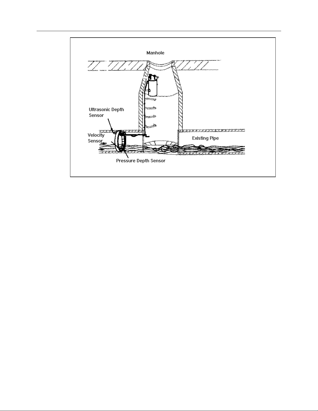
Typical 3600 Flow Monitor Installation
Typically, the monitor is attached to the inside wall of a manhole using bolts. Depth
and velocity flow sensors are installed in the sewer pipe to gather flow data. The
sensors are mounted on a stainless steel ring, usually placed upstream in the sewer
pipe. Cables connect the monitor in the manhole to the sensors in the sewer pipe. The
QS3600 flow monitor is linked to a central IBM-compatible personal computer with a
voice-grade telephone line and either an IS modem or an external modem unit
(EMU). (Data can also be acquired serially directly from the monitor with an
internal IS modem). This link allows you to communicate with the monitor,
configure the monitor, activate the monitor, collect data, and perform monitor
diagnostics from a remote location.
In order to measure the flow rate in a sewer pipe, the QS3600 flow monitor gathers
data on the depth and/or velocity of the flow. The monitor gets this data by
periodically scanning the sensors which are installed in the pipe. The monitor uses
two types of sensors to determine the depth of flow: the ultrasonic depth sensor and
the pressure depth sensor. The monitor has a Doppler velocity sensor to measure
flow velocity. See Chapter 2 for information on the monitor’s key hardware
components. See Chapter 3 for a more detailed explanation of monitor operation.

Intrinsic Safety
Intrinsic safety (IS) is a special certification awarded to equipment when its design
and manufacture meet the high standards of IS regulations . The main goal of IS
regulations is to prevent the electronic equipment from causing explosions in
potentially explosive environments. These environments are categorized as Class I,
Division 1, Groups C and D in the USA and as Zone 0 in Europe; the QS3600 flow
monitor is certified for use in these environments. IS regulations were created by
local and international standards organizations to regulate all electronic equipment
that operate in areas where hazardous gases are present (for example, in sewer
systems).
ADS field crews are trained to test all manholes for the presence of explosive gases
by sampling its atmosphere with a gas meter. When the amount of gas present
exceeds certain limits, the crew does not enter the manhole.
However, a flow monitor is mounted in a manhole for extended periods of time.
During this time, the amount of combustible gas may rise to dangerously high levels
without the field crew's knowledge. As a result, many cities require that all electronic
equipment installed in sewers be tested and certified as non-explosive. ADS
produces the QS3600 IS flow monitor to meet these requirements.
Introduction 1-5
Unique Features
The QS3600 flow monitor can be configured in two ways: by using a monitor with an
internal IS modem or by using a monitor with an external modem unit (EMU).
Country specific telecommunications standards and certifications will dictate whether
the internal IS modem or EMU is required. The external modem unit (EMU) houses
the modem and the power supply outside of the monitor and the manhole. The EMU
contains special circuitry to protect the circuits entering the hazardous area.
Special features of the QS3600 flow monitor include the following.
All QS3600 flow monitors are checked carefully before being shipped. Each
component is guaranteed to meet specifications. The pre-shipping inspection
is completed by internal quality inspectors.
All QS3600 flow monitors connect to 3600 compatible sensor cables. The
female connector is located on the flow monitor lid, while the male connector
is found on the sensor cables (unlike other ADS monitors). This arrangement
of connectors prevents mismatching with non-IS sensors. .
The monitor can be equipped with either an internal IS modem and telephone
interface box or with an external modem unit (EMU).
For the internal IS modem, cables are routed from the monitor to a phone
line interface box located on a pedestal or on the telephone pole. The

1-6 ADS 3600 Flow Monitor O&M Manual
monitor cables and the phone lines connect within this interface box
because IS standards require that telephone lines not be routed directly into
a manhole since it is a potentially explosive environment. An additional
precaution can be taken by using an ADS lightning protection module that
is located above the phone line interface box on the pedestal or telephone
pole and which stops high voltages before they reach the interface box.
An alternative to the internal IS modem is the external modem unit(EMU).
Two types of EMUs are available: one with an internal battery power
source and one which uses an external power source. The same IS
standards apply to the EMU which houses both the monitor's modem and
modem battery outside of the manhole. The EMU is either installed in an
above-ground customer supplied box, in a specially dug pit, or in a
pavement or sidewalk box. A cable then connects the EMU with the
monitor to allow communications between the monitor and a central
computer.
Only limited field repairs to the QS3600 are allowed; all other repairs must be
performed by an authorized technician. For information on allowable field
repairs, see “Maintenance Restrictions” on page 1-7.
Installation and IS Considerations
When installing the QS3600 flow monitor, carefully follow any local regulations for
the installation of IS equipment. For example, many cities only allow the use of IScertified flash lights in manholes. Some cities will not allow the use of an electric
drill–either battery powered or AC powered–in a manhole. In this case, air
(pneumatic) tools must be used.

Maintenance Restrictions
As mentioned earlier, all ADS QS3600 flow monitors are manufactured to meet IS
standards. The monitor’s IS certification can be voided instantly if proper
maintenance and service procedures are not followed. ADS must restrict certain
maintenance tasks to ADS IS certified technicians.
ADS allows you to perform only those maintenance tasks which do not require
opening the monitor housing. All other maintenance must be performed by ADS IScertified technicians. ADS technicians carefully inspect and document their repairs to
IS monitors. This inspection and documentation process provides legal protection
should the monitor's performance or safety be questioned. It is important to
understand that if the monitor’s housing is opened by unauthorized personnel, the IS
certification is compromised.
For your convenience, ADS allows you to
install and swap monitors,
install and swap sensors,
Introduction 1-7
clean sensors,
calibrate and confirm monitors, and
collect data.
Note: Please note that in all applications, only ADS Service Technicians are
authorized to perform component-level service on the QS3600.
This manual contains the correct procedures for performing routine installation and
maintenance on the QS3600. If you have any question about the procedures, or
regarding the level of service you are allowed to perform on a monitor, contact your
regional ADS office.

1-8 ADS 3600 Flow Monitor O&M Manual
Warnings, Certifications, FCC Compliance, and
Conformity
Changes or Modifications Changes or modifications to the QS3600 flow
monitor not expressly approved by the party responsible for compliance will void the
IS certification.
Personnel performing installation of the QS3600 flow monitor should carefully
follow the guidelines contained in this manual when installing and maintaining the
monitor. Failure to strictly adhere to these guidelines can result in personal injury
and can cause damage to the monitor, which would invalidate its warranty.
The QS3600 flow monitor is designed to be installed in combined and sanitary sewer
lines and manholes. This installation work is inherently dangerous. All applicable
safety guidelines should be followed and carried out by at least two fully trained and
qualified persons.
Intrinsically Safe (IS) Certification
Only authorized technicians can make certain repairs to the QS3600 IS flow monitor.
These repairs must be re-inspected by approved inspectors for continued IS
certification. If individuals other than approved technicians make the repairs, they
will void the monitor’s IS certification. For more information on allowable field
repairs, see “Maintenance Restrictions” on page 1-7.
FCC Compliance
To comply with the Federal Communications Commission (FCC), ADS
Environmental Services provides the following information about installing and
operating the 3600 internal modem DAA/3600 Monitor.
FCC Part 68 This equipment complies with FCC Rules, Part 68. It bears a label
displaying, among other information, the FCC registration number and ringer
equivalence number (REN). The user must provide this information to the telephone
company if requested.
The REN identifies the number of devices that may be connected to the telephone
line. Excessive RENs on the telephone line may prevent devices from ringing in
response to an incoming call. In most areas, the sum of the RENs should not exceed
five. To determine the number of devices you may connect to a line, as determined
by the RENs, contact your telephone company.
This equipment uses standard RJ11C jacks/plugs for connection to the telephone
network. These modular jacks/plugs are FCC compliant. They are designed for

Introduction 1-9
connection to the telephone network or premises wiring using compatible modular
jacks/plugs and cabling that comply with FCC Part 68 rules.
The telephone company may make changes in its facilities, equipment, operations, or
procedures that could affect the operation of this equipment. If this occurs, the
telephone company will provide advance notice so you can make the modifications
necessary to maintain uninterrupted service. In the unlikely event that this equipment
harms the telephone network, the telephone company will notify you that temporarily
discontinuing telephone service may be required. Notification will occur in advance
of discontinuation, or as soon as practically possible. They also will inform you of
your right to file a complaint with the FCC if necessary.
This equipment may not be used on public coin phone service provided by the
telephone company. Connection to party line service is subject to state tariffs.
This equipment is not field repairable. If you experience trouble with this equipment,
please refer to this manual for troubleshooting, replacement, or warranty information
or contact:
ADS Corporation
5030 Bradford Drive, Building 1, Suite 210
Huntsville, AL 35805
(256) 430-3366
FCC Part 15 This equipment has been tested and found to comply with the limits
for a Class A digital device pursuant to Part 15 of the FCC rules. These limits are
designed to provide reasonable protection against harmful interference in a residential
installation. This equipment generates, uses, and can radiate radio frequency energy
and if not installed and used in accordance with the instructions, may cause harmful
interference to radio communications. However, there is no guarantee that
interference will not occur in a particular installation. If this equipment does cause
harmful interference to radio or television reception (which can be determined by
turning the equipment off and on), you should try to correct the interference by one or
more of the following measures:
reorient or relocate the radio or television antenna,
move and/or increase the distance between the computer and the radio or
television, and
plug the computer in an outlet different than the radio or television.
If these suggestions do not help, consult ADS Corporation or an experienced
radio/television technician.
Additional Notice of Canadian Emissions Requirements
This digital apparatus does not exceed the Class A limits for radio noise emissions
from digital apparatus, which were set out in the Radio Interference Regulations of
the Canadian Department of Communications.

1-10 ADS 3600 Flow Monitor O&M Manual
Le present appareil numerique n'emet pas de bruits radioelectriques depassant les
limites applicables aux appareils numeriques (de la class A) prescrites dans le
Reglement sur le brouillage radioelectrique edicte par le ministere des
Communications du Canada.
Declaration of Conformity
For European (EC member country) applications, a Declaration of Conformity is
required to be kept on file at the facility responsible for repair and maintenance of
this equipment. If you have any questions about the Declaration of Conformity,
contact your regional ADS representative.
Sample Declaration of Conformity
C H A P T E R 2
Hardware
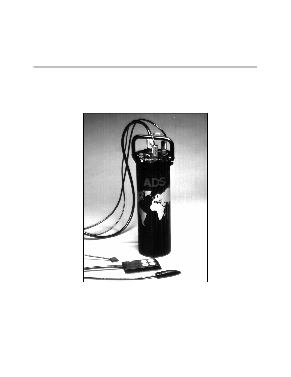
The QS3600 flow monitor is housed inside a cylindrical aluminum canister that is 62
cm (24 in.) long and 17 cm (6.6 in.) in diameter. The canister lid contains ultrasonic,
pressure, velocity sensor, and communication cable connections as well as rain gauge
and sampler communication cable connections. With the lid in place, the canister is
airtight and waterproof.
2-1
Warning
: Only ADS Service Technicians are authorized to perform
component level service on the QS3600. If the monitor’s housing is opened by
unauthorized personnel, its IS cert ification is compromised.
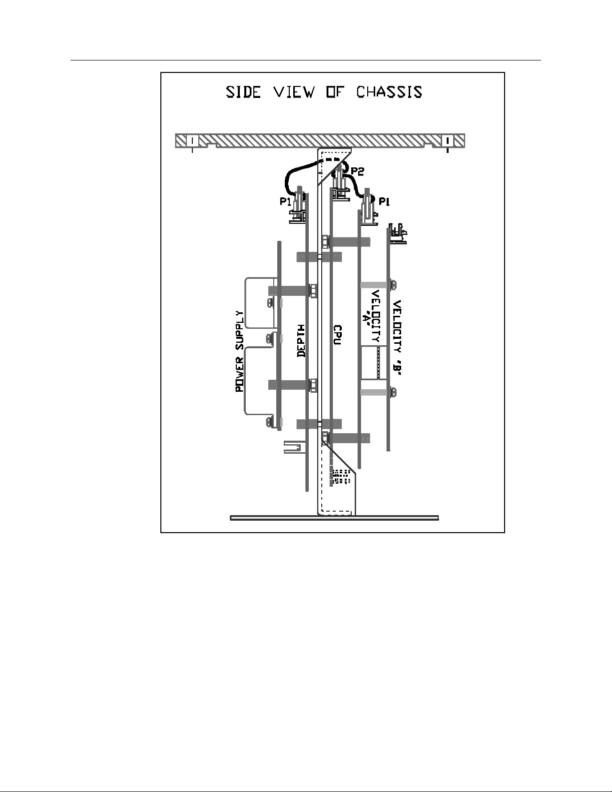
A one-piece chassis attaches to the inside of the monitor lid to pro vide a mounting
surface for the central processing board (CPU boar d) , the depth interface (for t he
ultrasonic level sensor and the pressure dept h sensor bo ar ds) , the velocity interface
(for the Doppler velocity sensor board), and the power supply board (with the internal
modem).
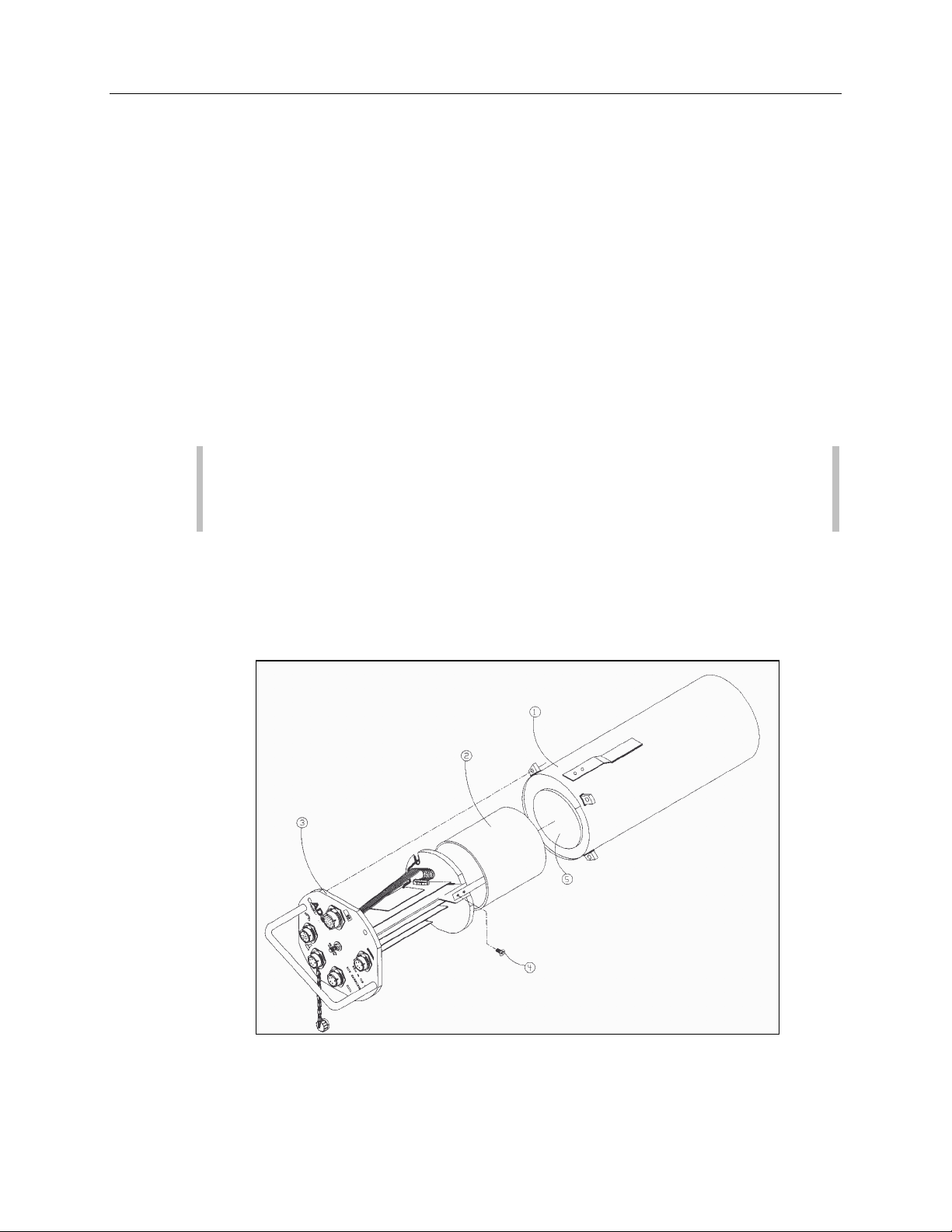
Assembly of the QS3600 IS Flow Monitor
(3) Lid Assembly (4 ) Screw to Attach Battery Pack (5) Foam Insert
(1) Aluminum Canister (2) Battery Pack

2-2 ADS 3600 Flow Monitor O&M Manual
Note: The depth board and velocity boards are also called the input/output
(I/O) boards.
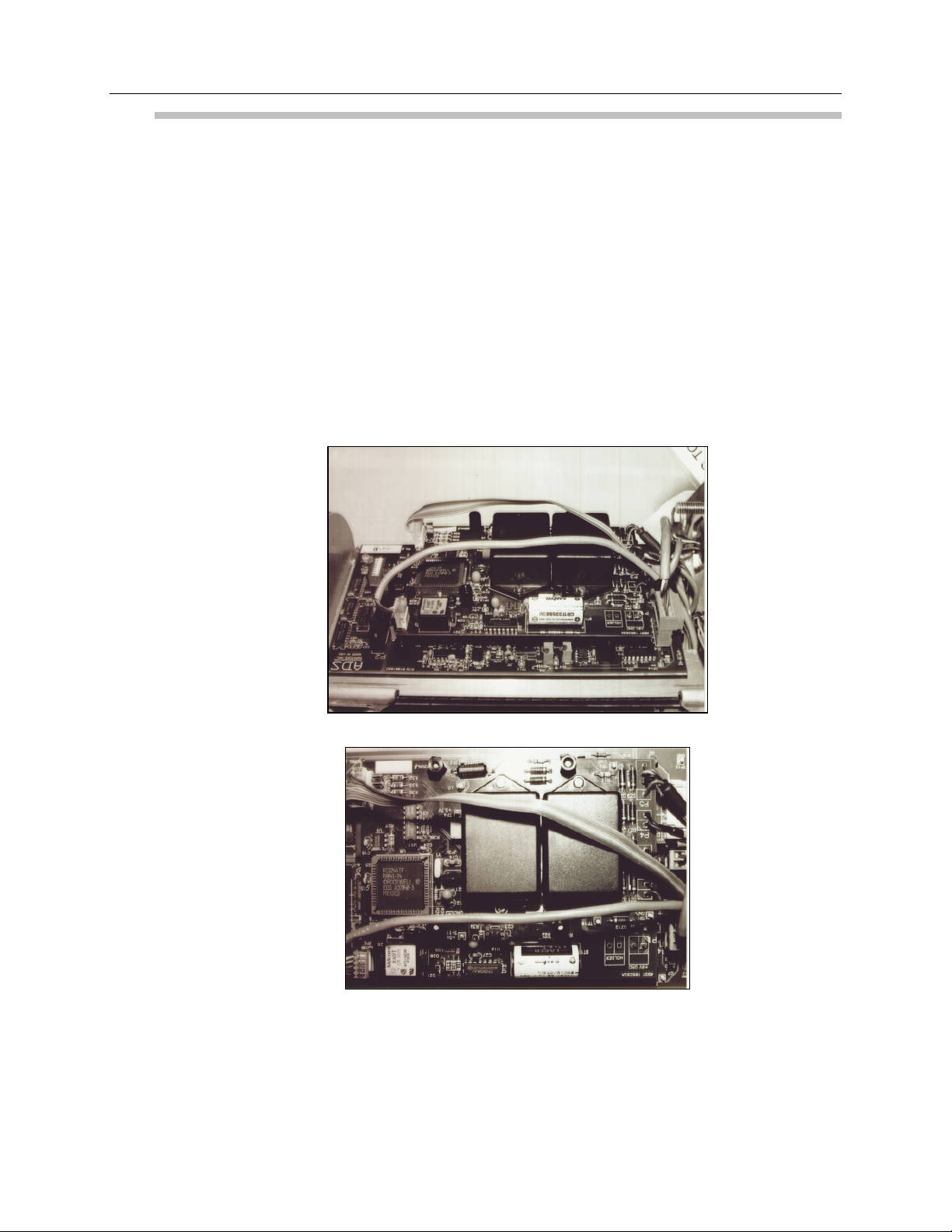
Opening the lid of the monitor and removing the lid assembly reveals the one-piece
chassis. The processor boar d is mounted to the chassis on the bott om of one side.
Two Doppler velocity boards are mounted on top of the processor board. The depth
board is mounted to t he other side of the chassis' frame. The IS modem is located on
the power supply board which is mounted on to p of the depth board. The processing,
depth, and velocity boards are connected with a ten-conductor ribbon cable.
A 9 V battery pack is attached to the bottom of the chassis. Cabling connects the
battery pack to the power supply board. The bottom of the housing is sealed.
Connector s for the following cables are installed on the lid of the canister:
the ultrasonic depth sensor cable,
z
the Doppler velocity sensor cable,
z
the pressure depth sensor cable,
z
the communications cable,
z
the rain gauge cable, and
z
t he sample r cab le.
z
The monitor can be sealed after the lid assembly is securely placed in the monitor.
To learn about: See page:
Major Components of the QS3600 Monitor ......................................... 2-3
Processor Board............................................................................. 2-3
Sensor Interface Boar ds .................................................................2-5
Flow Sensors..................................................................................2-5
Battery Pack...................................................................................2-5
IS Modem and Telephone Interface Box.........................................2-6
External Modem Unit.....................................................................2-7
Data Access Arrangement............................................................ 2-10

Major Components of the QS3600 Monitor
The major components of the QS3600 flow monitor include the processor board, t he
sensor interface boards, the batter y pack, and the flow sensors. Refer to Appendix A
for additional information regarding these components.
Processor Board
The processo r board contains the central processing unit (CPU). I t is mounted o n t he
bott om of the chassis card frame plate which is installed on the lid assembly chassis.
The processo r board is the center of all monitor activity, and is responsible for all of
the monitor's high-level functions, including
communications with the central computer,
z
communications with the sensor interface (I/O) boards,
z
data storage, and
z
Hardware 2-3
time-keeping.
z
2-4 ADS 3600 Flow Monitor O&M Manual
Side View of Flow Monito r Chassis and Assembly
The board allocates port ions of memory to firmware (permanently stored software),
data storage, and progr am manipulation and calculations. A light-emitting diode
(LED) is located on the pro cessor board and indicates the monitor's communication
status. When the processor board is involved in external communications, the LED is
ON. A second LED is used to indicate the current activity level of the processor
board: the brighter the light, the more wor k the processor bo ar d is doing. Discrete
input and output por ts, a monitor clock, and a memory battery are also located on the
board.

Hardware 2-5
The processo r board performs many functions; it
powers up each input board and provides each board with the parameters
z
required to carry out the appropriate oper ations,
periodically scans the sensor interface boards and the optional rain gauge input
z
to r etrieve and store data r eadings,
out p uts a discrete signal to a sampler,
z
transmits the stored data to the central computer for processing by
z
QuadraScan software after data is collected, and
maintains the date and time .
z
Sensor Interface Boards
The QS3600 flow monitor's chassis can hold up to two sensor interface subsystems:
one Doppler velocity subsystem which consists of two boards and
z
one depth subsystem which consists of one board that is used for both the
z
pressure depth sensor and the ultrasonic level sensor.
Each sensor interface subsystem communicates with its particular sensor(s) in order t o
provide the instructions necessary to collect the appropriate data, collect sensor
readings, and convert raw data to engineering units of measurement (instead of binary
counts).
Flow Sensors
As mentioned earlier, a QS3600 flow monitor can have up to three flow sensors: one
Doppler velocity sensor, one ultrasonic depth sensor, and one pressure depth sensor.
These flow sensors are mount ed on an expandable stainless steel ring that is placed in
the sewer pipe upstream from a manhole. Cables connect each sensor t o its interface
board thro ugh co nnectors on t he monitor's lid.
Battery Pack
The 9 V battery pack provides the power necessary to oper ate the monitor and
maintain the monitor memory. The monitor measures the battery voltage and signals a
warning when the power is low. The QS3600 battery pack (part number 106152)
meets IS requirements.
2-6 ADS 3600 Flow Monitor O&M Manual
IS Modem and Telephone Interface Box
If the QS3600 flow monitor uses an IS modem instead of an EMU, it is located within
the QS3600 monitor housing and complies with IS regulations. This modem
communicates with the central computer via a telephone interface box, located o n the
telephone pole or on a nearby pedestal. (The IS modem does not require a separate
battery for power; it uses the monitor’s battery pack.)
Routing the electricity through the telephone interface box prevents voltage from
going dir ec tly into the potentia lly explosive manh ole e n vir onmen t. To protec t the
telephone interface box from dangerous lightning and high voltages, the telephone
lines can first be r un thro ugh a lightning pr otectio n module (ADS part nu mber
103313A). The QS3600 flo w monitor can be programmed to communicate at various
baud r ate s. For more information on the mod em’s c ap abilities and installation, s ee
Chapter 5, “Monitor Installation and Activation.”
IS Modem on the Processor Board
IS Modem on the Processor Board
Hardware 2-7
External Modem Unit
An alternative way to communicate via a telephone line is to use an external modem
un it (EMU), which h ous es the mode m outs ide of the mon itor. Two type s of EMUs
exist: one with an internal battery power source and one which uses an external power
source. T he EMU may be buried in a sidewalk or pavement box at the end of a trench
dug away fr om the manhole, or the EMU may be bolted to a nearby wall.
Th e EMU fu nction s similarly to the inte rn al mod em a nd ca n be programmed to
communic ate at various b au d rates. F or more information on EM U c ap abilities and
installa tion, see C h apter 5, “ Monitor Ins talla tion an d Activation.”
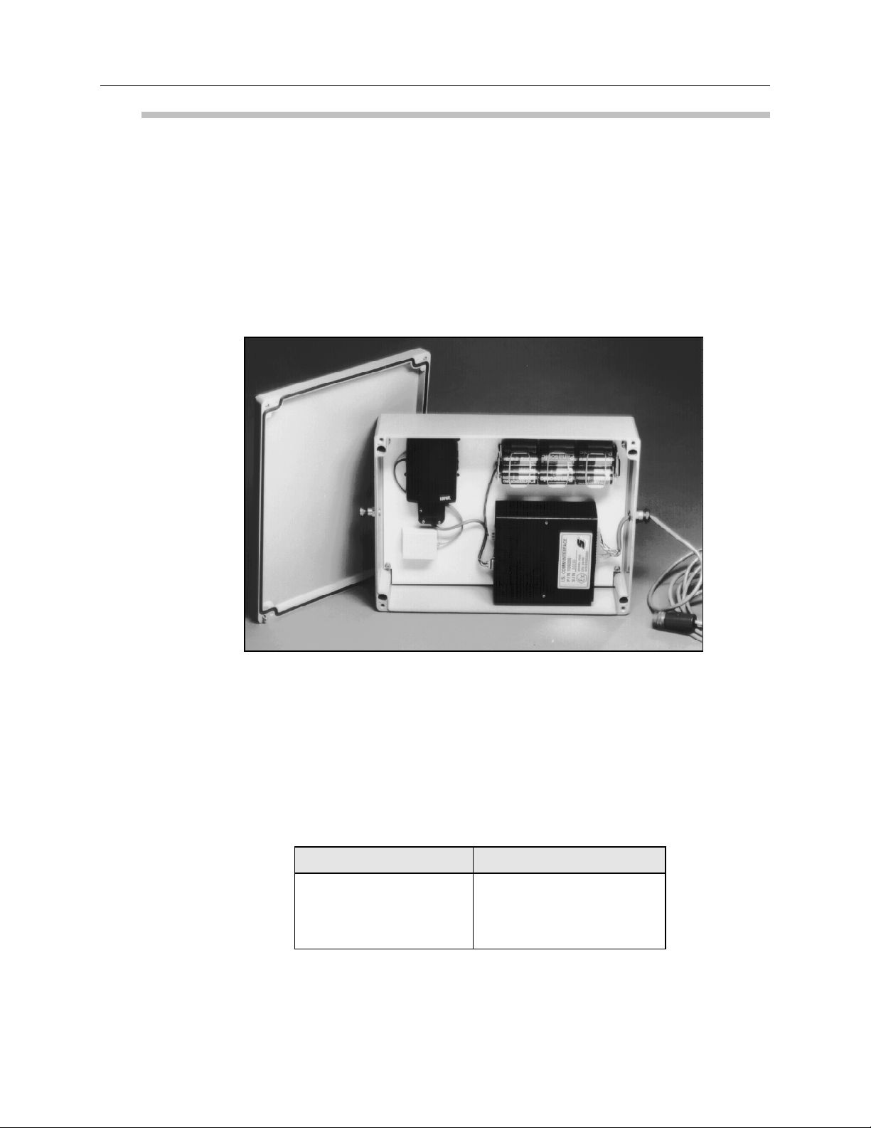
EMUInside View
Internal Power Source
The internally power ed E MU co nt ains a set of alkaline batteries that supply power for
t he mode m. This internally pow ered EMU is us ed in app lica tions wher e an external
power source is not available. An example of this application is the 3600 flow monitor
that t ypically collects data at a set time period, such as once per week. T he following
standard EMUs provide battery-powered modem commu nication:
ADS Part Number EMU Model
P/N 106223B United States
P/N 106223C British/Germ an
P/N 106223D French

2-8 ADS 3600 Flow Monitor O&M Manual
External Power Source
Some model 3600 flow monitors may require a continuous power sour ce, for example
real time flow monitor s use d in SC ADA ap plication s. T he exter n al modem unit
(EMU) supplied for SCADA applicat ions has a provision for continuous power from
an external power source. This can be accomplished in two ways: alternating current
(AC) or direct current (DC).
Note: For continuously po wer ed applications, the external power cable within
the monitor must be moved from a non-functioning connecto r and placed into
connector P 1, which is the connector to which the batter y is normally
connected. Additionally, the battery should be removed from the flow monit or
housing.
Due to the diversity of electr onics and telecommunications requirements abroad, ADS
only manufactures SCADA EMUs to meet t he specific r equirements of the United
Stat es. United St ates versions of external-powered SCADA EMUs are available with
a modem. However, International versions of external-powered SCADA EMUs are
available without a modem. The user of an International ver sion is responsible for
configuring the unit with any telecommunication options and for obtaining any agency
approvals for telecommunication equipment relevant to that count r y. ADS currently
manufactures the following SCADA EMUs:
ADS Part Number SCADA EMU Mod el
P/N 106328A International, External AC-Powered
P/N 106328B International, Ex ternal DC-Powered
P/N 106328E United States, Ext er nal AC-Powered
P/N 106328F United St ates, Ext er nal DC-Powered
External AC Power Source (optional)
ADS can provide a cable assembly which includes a wall so cket mount transformer to
provide the low voltage power needed by the EMU. In this version of the EMU, the
low voltage power sent to the EMU is used to operat e and power the 3600 flow
monitor, sensor s, modem, and EMU and to charge an int er nal NiCad batter y. The
only S CADA EMU external AC power cable cur r ently available through ADS is the
United States version with the following part number:
ADS Part Number External AC Power Cable
P/N 106330C United States
The above cable is 20 m (8 ft) in length. A wall receptacle or socket must be pro vided
within 20 m (8 ft) of the EMU location. A 25 m (10 ft) gr ound w ire is also p rovide d
in this cable to provide earth ground for the intrinsic safety barriers inside the EMU.
Eart h grounding is necessary to satisfy the int rinsic safety requirements of an
installation invo lving a 3600 and SCADA EMU using exter nal power. Therefore,

Hardware 2-9
when connecting the SCADA EMU to an AC power source using the ADS power
cable with t he t hree-pr ong wall plug transformer, make sure the power sour ce is earth
grounded.
Note: Cust omers using their own power cables must pin the SCADA EMU
connector according to the diagram displayed on the inside cover of the
SCADA EMU to ensure proper earth grounding.
In the event of power loss, the NiCad battery, located in the EMU, can provide
operat ing power for the 3600 flow monit or. The NiCad battery has been sized to
provide about six to eight hours of operat ion when the flo w monitor is taking readings
o n ce pe r five minute s and when the RTU is polling the mo nitor on ce pe r five minutes.
External DC Power Source (optional)
Th e EMU will also operat e from a user supplied 12 Vdc power source. T his power
source should be provided with some form of battery backup that is sufficient to
power the 3600 flow monit or during power out ages. The external power source
should provide from 11.5 V to 15.0 Vdc and a voltage ripple of 100 mV peak to peak.
The user supplied power source should be able to support the EMU and 3600 flo w
monitor at a maximum of 450 mA although only 290 mA is typically needed for t he
required time period. No internal bat tery backup exists in this configur ation. The
cable for this configuration is different from the AC powered configurat ion. The
follo wing SCADA EMU DC power cable is available for use in the United States or
Internationally:
ADS Part Number External DC Po wer Cable
P/N 106132A United States or International
Th is cable is 20 m (8 ft) long, with a 25 m (10 ft) wire to provid e e arth g round for the
intrinsic safety barriers. The appropriate connecto r for mating this cable t o the EMU
is provid ed at one end of the cable. The bare end of the cable connects to the DC
power supply [white wire to +12 V, black wire to ground(−)].
Eart h grounding is necessary to satisfy the int rinsic safety requirements of an
installation invo lving a 3600 and SCADA EMU using exter nal power. Therefore,
when connecting the SCADA EMU to a DC power source using the ADS power cable
with the exposed wires, connect the ground wire to the earth ground associated with
the power so ur ce.
Note: Customers using their own power cables must pin the SCADA EMU
connector according to the diagram displayed on the inside cover of the
SCADA EMU to ensure proper earth grounding.
The EMU cannot to lerate ext er nal power sour ce vo ltage dropout s or dro ops out side
the specified range regardless of dur ation. The typical external power sour ce would
be a fully charged lead acid battery; however, no internal bat tery backup exists in this

2-10 ADS 3600 Flow Monitor O&M Manual
conf igu ration. The refor e, if u tilizing a b attery as the exte rn al d c voltag e source, the
length of the unit operat ion is dependent on several fact ors, such as the battery amphour rating, the batter y charge stat e, the monitor configur ation, and the monit or
sample interval. These factors cannot be predicted by ADS.
Data Access Arrangement (DAA) for 3601 Flow Monitors
ADS manufactures the following DAA and communication cable for use with the 3601
flo w monitor:
ADS Part Number 3601 Hardware
P/N 106288A DAA
P/N 106298A - cabl e length comm unicati on c able
The communication cable connects the DAA to t he 3601 flow monitor. Or der s for
this cable must include the specific cable length required (in feet).

C H A P T E R 3
Flow Measurement
This chapter describes the QS3600’s integral role in the ADS flow measurement
process, including information on
l
monitor operation,
l
flow sensor operation,
l
data scrubbing (filtering erroneous data out of the data collected),
l
communications between the monitor and a computer, and
l
confirmation of the monitor’s accuracy.
3-1
To learn about: See page:
Monitor Operation ...............................................................................3-2
Monitor Activation.........................................................................3-2
Flow Sensor Measurement Techniques.................................................3-4
Upstream Installation......................................................................3-4
Quadredundancy.............................................................................3-4
Ultrasonic Depth Sensor.................................................................3-4
Pressure Depth Sensor....................................................................3-5
Doppler Velocity Sensor.................................................................3-6
Ultrasonic Depth Data Scrubbing .........................................................3-7
Transmitting Data to the Computer ......................................................3-8
Confirmation........................................................................................3-8

3-2 ADS 3600 Flow Monitor O&M Manual
Monitor Operation
A central computer communicates with the QS3600 using a telephone line and
modem. QuadraScan software must be installed on the computer, and site
configuration information must be defined before the QS3600 flow monitor can be
activated (see Chapter 5, “Monitor Installation and Activation,” and the QuadraScan
User’s Guide for more information on using QuadraScan software on the computer).
Site information is entered on the LIF (Location Information File) configuration
screens in QuadraScan. After the site information is defined, the monitor can be
activated.
Monitor Activation
Activating the monitor involves two tasks. First, the computer uses site configuration
information to build BASIC code and variable files for the site. Then, the computer
downloads the BASIC code and variable files to the monitor. The monitor uses the
instructions contained in these files to
l
activate the depth and velocity sensors and read the values they gather,
l
store data on the processor board for retrieval by the computer and
QuadraScan software,
l
record pulses from a rain gauge,
l
send signals to a sampler, and
l
monitor the status of selected events, initiate telephone calls to the event
notification station, and report event status changes.
The computer and QuadraScan software
l
activate the monitor,
l
collect data from monitor memory,
l
process the data to determine flow rates,
l
generate graphical and tabular reports of the flow rates,
l
store data on the computer's hard disk files,
l
synchronize the monitor clock with the computer master clock upon activation,
l
maintain a hardware log of all conversations between the computer and the
monitor,
l
maintain an exception log of computer/monitor conversations that have had
problems, and
l
perform diagnostics.

Flow Measurement 3-3
Note: Refer to the QuadraScan User's Guide (version 5.01 or higher) for
additional information and instructions on the interaction between the monitor
and QuadraScan.
The QS3600 can be used in real time applications in which the flow monitor will
interface with the remote terminal unit (RTU). For more information on using the
QS3600 in real time applications, refer to Using ADS Flow Monitors for Real Time
Applications, document number 530006**, or contact your regional ADS office.

3-4 ADS 3600 Flow Monitor O&M Manual
Flow Sensor Measurement Techniques
The ultrasonic depth sensor, the pressure depth sensor, and the Doppler velocity
sensor gather raw flow data. The ultrasonic and pressure depth sensors use
independent measurement techniques to collect information about the depth of flow.
The Doppler velocity sensor gathers flow velocity data.
Upstream Installation
The sensors are mounted on a ring that is installed in the sewer pipe upstream from a
manhole. Upstream installation minimizes hydraulic effects and erroneous data
readings.
The process of installing the sensors in the incoming pipe is patented by ADS. The
system's hydraulics are much more stable and uniform in the incoming pipe than they
are in the manhole invert or in the outgoing pipe. In addition, upstream installation
minimizes monitoring errors caused by foamy waters, flow waves, sewer line noise,
and non-laminar flow.
Quadredundancy
Each ultrasonic depth sensor contains four ultrasonic transducers. To take a reading,
one transducer transmits a sound wave while a second transducer listens for the
returning echo. Taking readings with four transducer pairs gives the sensor
quadredundancy, which ensures greater sensor reading reliability.
In one firing of the ultrasonic depth sensor, each of the four sensor pairs takes thirtytwo readings. All false and multiple echoes are discarded. The good readings are
averaged to arrive at the final reading for each pair. The readings from each sensor
pair are then averaged into one final value. Refer to Appendix A for a technical
discussion of the ultrasonic depth system.
Ultrasonic Depth Sensor
The ultrasonic depth sensor, also known as a bat, is mounted at the crown (soffit) of
the pipe. The ultrasonic depth sensor transmits sound waves from the top of the pipe
to the surface of the flow. Then, it measures the time elapsed between transmission
and reception of the sound signal. This distance between the sensor face and flow
surface is the range. Using this elapsed time and the speed of sound, the ultrasonic
depth sensor can calculate the depth of the flow by subtracting the range from the pipe
diameter. The monitor compensates for air temperature by using the temperature

Flow Measurement 3-5
recorded by one of two temperature sensors mounted inside the ultrasonic depth
sensor.
Enhanced firmware (permanently stored software) for the ultrasonic level sensor has
been added to the 3600 monitor to increase its capabilities. While the appearance and
composition of the ultrasonic level sensor is unchanged, this firmware stores an
algorithm that allows the updated sensor to filter out noise caused by bad signals that
return from the apron, side connections, rungs, broken pipes, or drop connections.
With previous sensor data, the data analyst was required to examine and filter out
noise readings that occurred when a sensor was not working properly. Now, the 3600
monitor uses this improved algorithm to filter out bad signals automatically. It also
produces more accurate data, yields one final average, and decreases the amount of
data that has to be stored.
Basically, each time the monitor fires the sensors and takes a reading, the algorithm
triggers two separate processes. First, the algorithm automatically determines a range
window, or set of standards, for good return echoes. The analog return signal is
digitized, and the sensor fires all 12 pairs five times each for a total of 60 firings. (In
earlier depth sensor design, only four pairs were fired.) The algorithm then takes an
average of the pairs to use in determining the range. The range is set by scanning
through the digital data and recording the strongest returning echoes, and a range
window is created around these echoes. Thereafter, the sensor accepts echoes only
within that range; bad signals are screened out.
Second, the monitor uses the standards set by the algorithm in the first sensor firing to
process the return echoes and determine the range actually used to record depth of
flow in the pipe. The monitor fires the sensors, which take 32 analog readings of each
of the 12 pairs (384 firings) because the analog signals produce a greater resolution
and are more accurate. The range window is then applied to each of the 32 readings,
and the signals outside of that window are screened out; this process is called
scrubbing. Interpair and intrapair averages are taken; the scrubbing routine is applied
again, and the algorithm produces one final range. In order to save memory space,
this single range is stored in memory rather than the four ranges used in previous
designs.
Pressure Depth Sensor
The pressure depth sensor, or pressure mouse, is typically placed at the bottom of the
pipe. This depth sensor can measure depths greater than full pipe (surcharges),
whereas the ultrasonic depth sensor only measures depths up to full pipe capacity.
The pressure sensor contains a differential pressure transducer which transmits an
output voltage corresponding to the difference between the water pressure and the air
pressure in the sewer. Water pressure is measured through a port on the underside of
the pressure sensor. Air pressure is measured using an integral vent tube which runs
to the top of the manhole. By reading the difference in pressures, the depth board
 Loading...