

Page 1

Compressed Air Line From Operatories
Terminating In 1/2" Or 3/8" FPT
(Provided By Plumber)
2' Clearance
Cold Water Inlet With Shut Off
Terminating In 1/2" Or 1/4" FPT
(Provided By Plumber)
Installation & Operation
Organizer™ Systems
Small, Medium & Large Cart Models
2" PVC Vent To Outside
(Provided By Plumber)
2 Ft. Flex Tube
6" Clearance
3/4" Flex Line To Sewer Drain
(1 1/2" P-Trap With 1" Air Gap Shown)
Vacuum Inlet From Operatories
(Size According To Unit/Office Sizing Chart)
(Provided By Plumber)
Vacuum Inlet Flex Line
(Provided)
Description:
Apollo Dental Products’ Organizer™ Vacuum and Air Systems have been tested and approved by various regulatory test agencies.
The following list contains ADP file numbers that may be helpful if questions arise regarding installation inspections;
Underwriter’s Laboratories .............................. File Number: MH13627
U.S. Food and Drug Administration .................... File Number: 2937927
City of Los Angeles Mechanical Test Labs............. File Number: M880066
The Organizer™ System should only be installed by qualified technical personnel. Should any questions arise during installation, call
our Technical Support Department between the hours of 6:00 am and 4:00 pm (PST) at 800/233 4151.
Unpacking the System:
1. Place boxed unit on level surface with enough space to lower the ramps and roll the unit onto the floor. This will require
36 inches plus the width of the pallet to clear the unit when it reaches the floor.
2. Remove cardboard shipping carton from pallet.
3. Unbolt shipping feet from platform.
4. Unpin shipping feet from front of unit; pull feet from mount in back of unit. DO NOT DISCARD MOUNTING FEET.
5. Fold down unloading ramps and verify the edges are on the pallet and ready to unload unit.
6. Unlock caster wheels to allow unit to roll.
7. With one person in front of the unit, and one behind it, gently roll the unit down the ramps and off the pallet to the floor.
8. Roll the unit to the equipment room or installation location.
9. Once unit is rolled into final installation location, lock caster wheels and re-install mounting feet by sliding feet into rear mounts
and bolting unit securely to the floor or wall.
Note: When installing the Organizer™ System, it is important to place the unit in an air conditioned room with
adequate ventilation. Failure to do so could cause premature loss of system performance and void warranty.
A 2 foot clearance is required on the left side and at least 6 inches on the back and right side.
Apollo Dental Products, Inc. • 245 W. Dakota Ave. • Clovis, CA 93612 • Technical Support
559/292-1444 • 800/233-4151 • Fax 559/292-1555 • www.apollodental.com
Page 1
AMI60900 Rev. 1/02
Page 2
Installation & Operation
Organizer™ Systems
Technical Service - (800) 233-4151
Organizer™ Specifications & Dimensions:
Small Cart 02SLB 02SLG 02SLU 02SOB 02SOG 02SOU
Max. Users 222 222
Width 24.25” 24.25” 24.25” 24.25” 24.25” 24.25”
Depth 29” 29” 29” 29” 29” 29”
Height 56” 56” 56” 56” 56” 56”
Weight 353 lbs 353 lbs 353 lbs 303 lbs 303 lbs 303 lbs
Vac HP 1111 11
Comp HP 1111 11
Volt 208 1Ph 208 1Ph 208 1Ph 208 1Ph 208 1Ph 208 1Ph
Vac. Amp 8.1 8.1 8.1 8.1 8.1 8.1
Comp. Amp 7.2 7.2 7.2 5.2 5.2 5.2
Hz 60 60 60 60 60 60
Wire Ga. 10 10 10 10 10 10
Vac. Breaker 20 20 20 20 20 20
Comp. Breaker 20 20 20 20 20 20
Vac. Inlet Size 3/4” 3/4” 3/4” 3/4” 3/4” 3/4”
Medium Cart 04MLB 04MLG 04MLU 04MOB 04MOG 04MOU
Max. Users 444 444
Width 37.25” 37.25” 37.25” 37.25” 37.25” 37.25”
Depth 29” 29” 29” 29” 29” 29”
Height 59” 59” 59” 59” 59” 59”
Weight 535 lbs 535 lbs 535 lbs 455 lbs 455 lbs 455 lbs
Vac HP 2222 22
Comp HP 2222 22
Volt 208 1Ph 208 1Ph 208 1Ph 208 1Ph 208 1Ph 208 1Ph
Vac. Amp 16.2 16.2 16.2 16.2 16.2 16.2
Comp. Amp 14.4 14.4 14.4 10.4 10.4 10.4
Hz 60 60 60 60 60 60
Wire Ga. 10 10 10 10 10 10
Vac. Breaker 30 30 30 30 30 30
Comp. Breaker 30 30 30 30 30 30
Vac. Inlet Size 1” 1” 1” 1” 1” 1”
Large Cart 06LLB 06LLG 06LLU 06LOB 06LOG 06LOU
Max. Users 666 666
Width 50” 50” 50” 50” 50” 50”
Depth 29” 29” 29” 29” 29” 29”
Height 61” 61” 61” 61” 61” 61”
Weight 889 lbs 889 lbs 889 lbs 770 lbs 770 lbs 770 lbs
Vac HP 3333 33
Comp HP 3333 33
Volt 208 1Ph 208 1Ph 208 1Ph 208 1Ph 208 1Ph 208 1Ph
Vac. Amp 24.3 24.3 24.3 24.3 24.3 24.3
Comp. Amp 21.6 21.6 21.6 15.6 15.6 15.6
Hz 60 60 60 60 60 60
Wire Ga. 10 10 10 10 10 10
Vac. Breaker 40 40 40 40 40 40
Comp. Breaker 40 40 40 40 40 40
Vac. Inlet Size 1 1/4” 1 1/4” 1 1/4” 1 1/4” 1 1/4” 1 1/4”
Page 2 AMI60900 Rev. 1/02
Page 3

Installation & Operation
Organizer™ Systems
Technical Service - (800) 233-4151
A. Electrical Hook-up Requirements:
Line Voltage (208-220V 60Hz)
Depending on the cart size of the Organizer™ unit being installed, disconnects with correctly rated breaker sizes and ground
connections will be required; one for the vacuum equipment and one for the compressor equipment within the cart. Refer to
preceding table for proper breaker size for the unit you are installing.
Low Voltage Control (24V)
18-3 thermostat wire must be installed from each remote control switch to the back of the Organizer™ Gauge/Control Panel.
The thermostat wire is connected into the existing switch wiring using the wire nuts existing on the switches. Lighted
switches require red and white wires for bulb, the red and blue connection control low voltage switching of vacuum and
compressor units.
NOTES: Dedicated electrical circuits with circuit breakers and approved grounds must be provided for the vacuum system, and the compressor system. Ambient
temperature must be within the range of 40 degrees Fahrenheit minimum (4 degrees C) to 100 degrees Fahrenheit (38 degrees C) maximum. All systems to be
installed according to local plumbing and electrical codes. Never operate the equipment without complete and proper grounding.
B. Plumbing Hook-up Requirements:
Vacuum Units:
Water Supply Line (Recommended)
1/4 inch (13mm) cold water supply line with shut off valve terminating in 1/2 inch FPT. The line must be flushed out prior to
connection to the vacuum unit(s).
IMPORTANT: Water is essential for the operation and longevity of the vacuum pump. The supply must not be
restricted or interrupted during operation. Water with high mineral content may cause mineral build-up and
create water starvation, leading to seal failure. A water softener and filter are recommended for this
situation.
Waste Line
Water and air exhaust to sewer line terminating in:
Option A- Floor sink.
Option B- A “P”-trap adapted to 3/4 inch (19mm) PVC slip connection. Local building codes may require a 1 inch
(25mm) air gap. The “P”-trap must not be located more than 6” above the floor.
Vacuum Line
Refer to the preceding table to determine correct vacuum line termination size for the unit being installed.
Vacuum Vent Line
2 inch PVC pipe vent to outside.
IMPORTANT: Continuously running sinks or cuspidors must NEVER be connected to the vacuum
piping system.
Compressor Units:
Operatory Air Line Termination
3/8 inch or 1/2 inch FPT termination to office supply line. Connect flex line from shut off valve on top of Organizer™ cart
to office supply line.
Fresh Air Intake
1 1/2 inch vent to outside terminating in 1 inch slip connection (Small and Medium Carts).
1 1/2 inch vent to outside terminating in 1 1/2 inch slip connection (Large Cart).
Remove Oil Filler Plugs
Remove plug(s) from oil filler necks on lubricated compressor heads and check oil levels before operation.
Page 3
AMI60900 Rev. 1/02
Page 4

Installation & Operation
Organizer™ Systems
Technical Service - (800) 233-4151
C. Installing the System:
1. Once the Organizer™ unit is in correct installation location, lock caster wheels (2 foot clearance is required on the left side,
and a 6 inch clearance in the back and right side).
2. Install floor or wall mounting feet horizontally on the floor or vertically into a secure wall to prevent unit from shifting.
3. Place condensate drain canister next to unit on the floor. Connect one end of 3/8 inch polyflow tubing into tee fitting below
desiccant chamber, and the other end into fitting on lid of canister.
4. Connect provided water supply line for vacuums into water supply line using provided 1/4 or 1/2 inch fitting.
Note: It is recommended that the water supply line be flushed with at least 5 gallons of water prior to connection
to the vacuum system. (Sediment in water lines of new buildings is common.)
5. Connect operatory vacuum line to the vacuum intake line located on either side of cart using provided suction hose.
Cement the suction hose using PVC glue.
6. Attach provided 3/4 inch vacuum drain hose to drain line on either side of cart and into a “P”-trap or floor sink.
Cement with PVC glue.
7. Connect vacuum exhaust line to 2 inch PVC vent pipe.
8. Install flexible compressed air line from valve on top of cart to operatory supply line.
9. Verify that all switches are in the off position, and connect high voltage electrical supply lines to approved disconnects with
proper breakers and grounds. See previous table for unit requirements.
D. Initial Start-Up:
Vacuum System
1. Open water supply valve at source and on manifold inside cart door. Check for water leaks.
2. Start the vacuum pump(s) by pressing all of the vacuum switches to the on position.
3. Check the drain line to verify that water is flowing through the system.
IMPORTANT: Do not run pump without full pressure water supply, or serious pump seal damage could result.
4. Check the vacuum gauge to ensure that all pumps are functioning properly. Vacuum pressure is preset at the factory to
10 inches Hg.
Compressor System
1. Make sure shut off valve on top of cart is closed.
2. Turn on compressor system. One switch controls all compressor heads in a multiple system.
3. The system will run until the storage tank pressure reaches 100 psi, then shut off automatically using a preset pressure switch.
4. Monitor tank pressure for two minutes to verify that there are no air leaks in the system. To check more closely apply soapy
water to plumbing joints to check possible leak paths. Care must be taken not to drip water on nearby electrical components
and avoid electrical shock.
5. Slowly open the supply valve on top of the cart to supply the office with compressed air. After intervals of 2 and 10 minutes
check the storage tank pressure gauge to confirm that no air leaks exist. If the pressure has dropped in this time, or the unit
has cycled, a leak exists. Locate all leaks and repair as necessary.
IMPORTANT: Seal All Air leaks! Air Leaks Are the Main Cause of Compressor Failure!
6. Be sure to complete and fax or mail in the warranty card for this unit within 10 days of installation to effect warranty.
7. Store this installation manual for future reference.
Page 4
AMI60900 Rev. 1/02
Page 5
Installation & Operation
Organizer™ Systems
Technical Service - (800) 233-4151
E. Vacuum Level Adjustment:
1. Open front access panel on cart.
2. The vacuum valve and filter are located horizontally behind the vacuum inlet strainer.
3. Remove the filter and valve from the PVC elbow.
4. Using a 1/4 inch nutdriver and a phillips screwdriver adjust the center mounted screw within the valve. Each full clockwise
turn increases the vacuum level by approximately 2 inches Hg. The vacuum level range is between 6 and 13 inches Hg
(27 to 44 KPa).
5. Reinstall filter and valve to test vacuum level and repeat steps as necessary until desired vacuum level is reached.
F. Maintenance:
Daily Weekly Monthly Semi-Annually Annually
Check/Verify Proper Operation of Cooling Fans •••
Check Drains In Vacuum Tray-Free of Debris •••
Vacuum System
Cleanse Vacuum Piping System •••
Cleanse Vacuum Pump Intake Strainer •••
Clean In-Operatory Strainers •••
Check Vacuum Level •••
Clean and Dust Off Vacuum Pump •••
Replace Recycler Return Line •••
Clean or Replace Relief/Regulator Filter •••
Clean Water Inlet Strainer •••
Compressor System
Check Oil Level (Lub. Comp Models Only) •••
Empty Condensate Drain Canister •••
Check Drying System Moisture Indicator •••
(If Pink or White = Run Manual Purge)
Check Pump-up Times (Between 25-40 secs) •••
Clean and Dust Off Air Compressor •••
Change Compressor Oil (Lub. Comp. Models) •••
Replace Air Intake Filters/Mufflers •••
Replace Ultrair Filter Element •••
Page 5
AMI60900 Rev. 1/02
Page 6
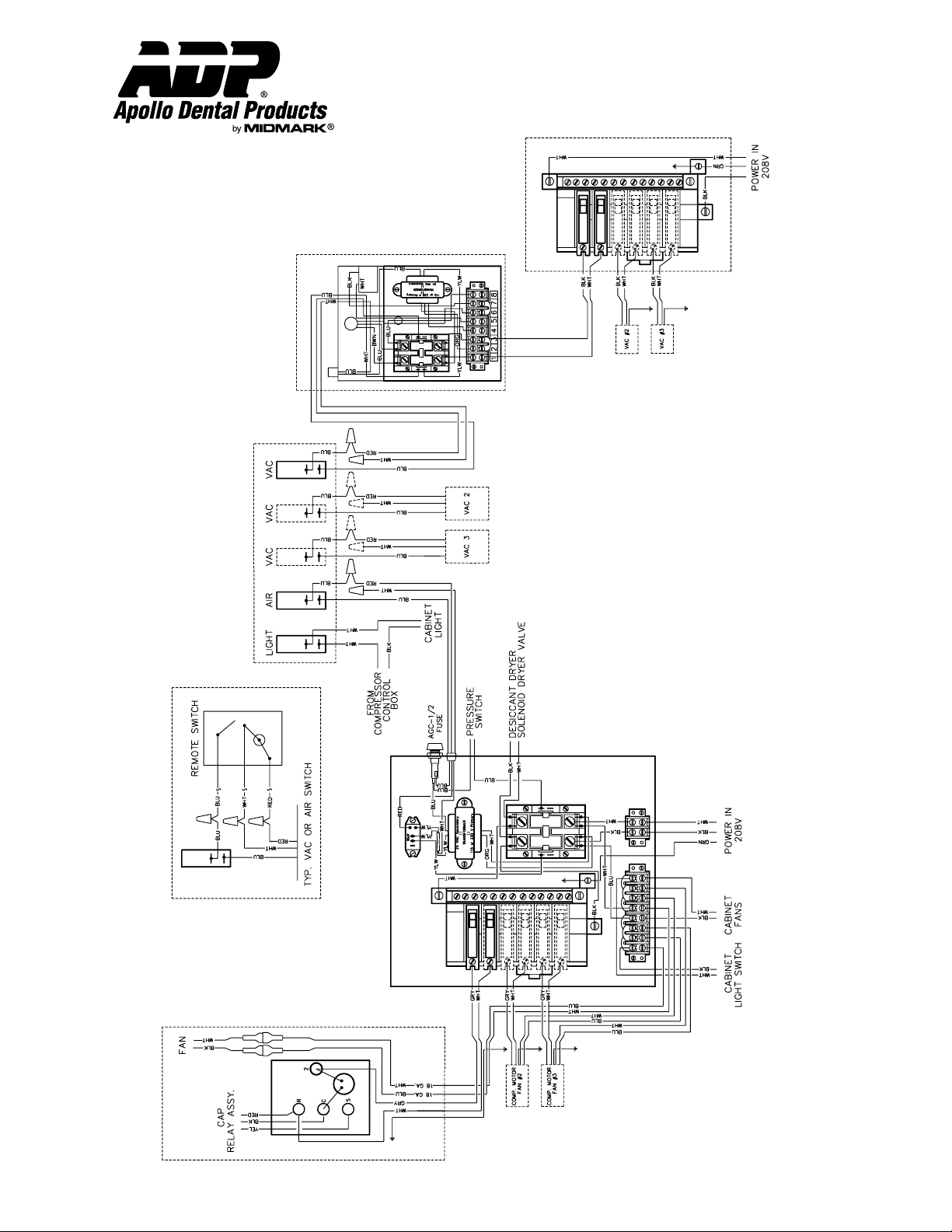
VAC. CIRCUIT BREAKER BOX
#1 VAC.
CONTROL PANEL
LOW VOLTAGE
REMOTE CONTROL
COMPRESSOR
CONTROL
BOX
#1 COMP. MOTOR & FAN
G. Wiring Diagram:
Installation & Operation
Organizer™ Systems
Technical Service - (800) 233-4151
Page 6
AMI60900 Rev. 1/02
Page 7
H. Vacuum and Compressor Service / Maintenance:
Installation & Operation
Organizer™ Systems
Technical Service - (800) 233-4151
Vacuum Pump Access
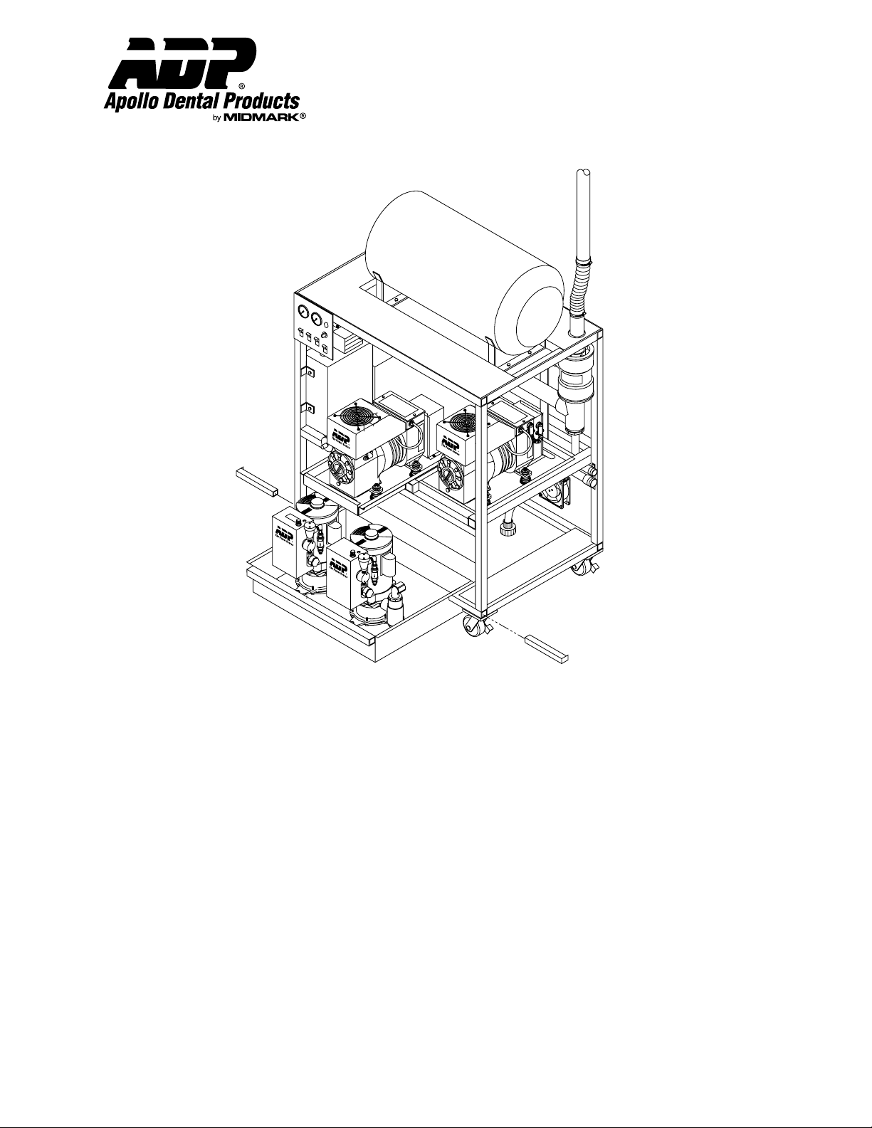
To service vacuum pump(s), the lower tray of the Organizer™ cart pulls out.
1. The light switch on the control panel operates a fluorescent light in the lower left portion of the cart.
2. First unpin the locking tubes in the lower front corners of the cart.
3. Remove front cover of cart by turning fasteners counterclockwise until they click.
4. Verify that the breakers located within the cart are in the off positions by removing the left side panel. Turn off as
required to avoid electrical shock hazard while working inside cart.
5. Remove the locking tubes in the lower front corners by pulling them out to the sides. The tray may have to be slightly
lifted to relieve the weight from the tubes.
6. Disconnect the internal union connection on the vacuum intake line located to the left of the cart after the strainer.
7. Lift and pull out the lower vacuum tray to service vacuum pumps. The tray should not be pulled out more than 2/3 of
the way out, as the exhaust and water feed lines can be stretched and/or pinched.
8. To remove a vacuum pump remove three wing nuts on pump base.
9. Unplug the high voltage lines within the individual vacuum electrical box.
10. Undo the low voltage switching wires on top of the vacuum electrical box.
11. Disconnect the intake and exhaust line unions on the pumps.
12. Remove the pumps as necessary.
13. Installatiion is the reverse of the previous steps.
Page 7
AMI60900 Rev. 1/02
Page 8

Installation & Operation
Organizer™ Systems
Technical Service - (800) 233-4151
Compressor Head Access
To service individual compressor heads, the Organizer™ is equipped with sliding compressor trays and an internal
fluorescent light inside the cart.
1. First verify that the breakers located within the cart are in the off positions by removing the left side panel.
Turn off as required to avoid electrical shock hazard while working inside cart.
2. Remove front cover of cart by turning fasteners counterclockwise until they click.
3. Remove pins located in the front corners of the compressor trays.
4. The compressors will slide out approximately 2/3 of the way out to service compressors.
5. Disconnect air pressure line at compressor head.
6. To remove a compressor for replacement, first unplug high voltage lines to the rear of the compressor unit and
disconnect conduit.
7. Disconnect air intake line at filter/muffler.
8. Make sure that most of the compressor’s weight rests on the slides to the rear of the tray so it cannot tip out of the
cart. With a 1/4 inch nut driver remove the lower bracket under compressor tray.
9. Pull out compressor tray carefully and using both handles at opposite ends of the tray, lift the unit out of the cart.
10. Installation is the reverse of the previous steps.
Page 8
AMI60900 Rev. 1/02
Page 9
18
Installation & Operation
Organizer™ Systems
Technical Service - (800) 233-4151
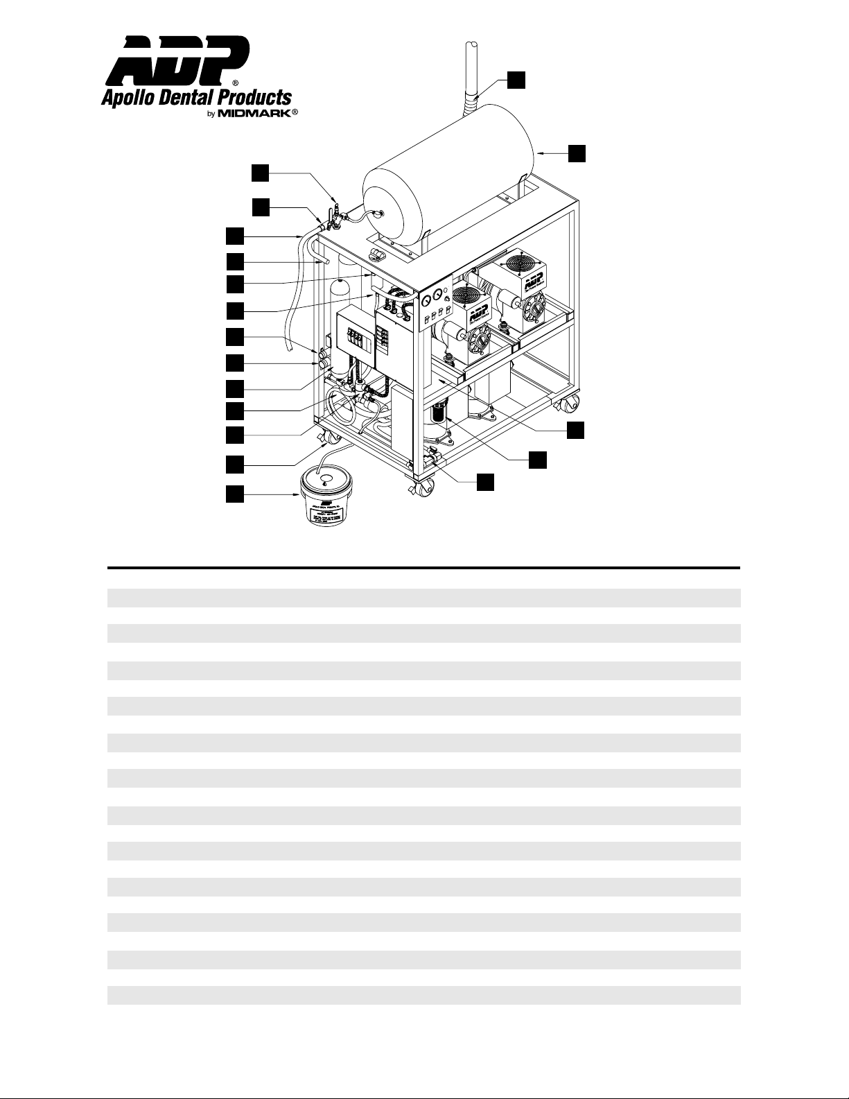
A. Organizer™ Cart Components
1
2
3
4
5
6
7
8
9
10
11
12
13
17
16
15
14
Item Description Quantity Small Cart Quantity Medium Cart Quantity Large Cart
1 Pressure Relief Valve 1 PVV50560 1 PVV50560 1 PVV50560
2 Ball Valve 1 PVV50500 1 PVV50500 1 PVV50500
3 Hose 1 SPA95102 1 SPA95102 1 SPA95102
4 Handle 4 STK96040 4 STK96040 4 STK96040
5 Ultrair Filter Assembly 1 ACA85215 1 ACA85215 1 ACA85215
5a Element Only .01 Micron 1 PFM85210 1 PFM85210 1 PFM85210
5b Float Assembly, Ultrair 1 ACA85210 1 ACA85210 1 ACA85210
5c Sight Glass, Ultrair 1 AAP85210 1 AAP85210 1 AAP85210
6 Separator, Vacuum 1 AVA95763 1 AVA96764 1 AVA96765
7 Drain Manifold 1 SVA97020 1 SVA97020 1 SVA97020
8 Intake Manifold 1 SVA97011 1 SVA97021 1 SVA97031
9 Desiccant Dryer Assembly 1 STK95340 1 STK95340 1 STK95341
10 Fan, Organizer Main 2 EMS10310 3 EMS10310 3 EMS10310
11 Valve, Quick Exhaust 1 PVV70502 1 PVV70502 1 PVV70502
11a Kit, Solenoid Repair 1 ACA85332 1 ACA85332 1 ACA85332
11b Coil, Solenoid Valve 1 ECO10118 1 ECO10118 1 ECO10118
12 Caster, Wheel 4 MMS73040 4 MMS73040 4 MMS73040
13 Condensate Drain Canister 1 SPA95400 1 SPA95400 1 SPA95400
14 Manifold, Water Supply 1 SVA95771 1 SVA95772 1 SVA95773
15 Vacuum Intake Strainer 1 PVC50706 1 PVC50706 1 PVC50708
15a Dispos-A-Bowl 1 AVA60000 1 AVA60010 1 AVA60020
16 Valve, Vacuum Relief 1 PVV85981 1 PVV85981 1 PVV85981
16a Filter, Vacuum Relief Valve 1 SVA95819 1 SVA95819 1 SVA95819
17 Storage Tank 1 TST91010 1 TST91020 1 TST91030
18 Flex Tube Exhaust Extension SVA95939 1 SVA95939 SVA95939
Page 9 AMI60900 Rev. 1/02
Page 10
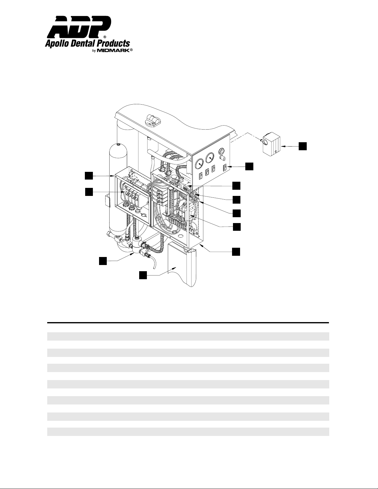
B. Organizer™ Electrical Components
1
2
Installation & Operation
Organizer™ Systems
Technical Service - (800) 233-4151
11
10
9
8
7
6
5
3
4
Item Description Quantity Small Cart Quantity Medium Cart Quantity Large Cart
1 Platform, Vacuum Electrical 1 SEA98500 1 SEA98520 1 SEA98521
2 Circuit Breaker, 10A 4 ECS10510 8 ECS10510 12 ECS10510
2a Bridge, Circuit Breaker 2 EMS10505 4 EMS10505 6 EMS10505
3 Valve, Quick Exhaust 1 PVV70502 1 PVV70502 1 PVV70502
3a Coil Only, Valve Q.EV. 1 ECO10118 1 ECO10118 1 ECO10118
3b Kit, Solenoid Repair 1 ACA85332 1 ACA85332 1 ACA85332
4 Assembly, Fluorescent Light 1 EMS10942 1 EMS10942 1 EMS10942
5 Platform, Compressor Electrical 1 SEA98110 1 SEA98110 1 SEA98110
6 Relay, Low Voltage Control 1 ETR10460 1 ETR10460 1 ETR10460
7 Fuse Holder 1 EMS10935 1 EMS10935 1 EMS10935
7a Fuse, 1/2 Amp 1 EMS10930 1 EMS10930 1 EMS10930
8 Transformer, 24V 1 SEA95050 1 SEA95050 1 SEA95050
9 Relay, SPDT 24V 1 ETR10455 1 ETR10455 1 ETR10455
10 Switch, Panel Orange Indicator 3 ECS10440 4 ECS10440 5 ECS10440
11 Switch, Pressure 1 ECS10445 1 ECS10445 1 ECS10445
Page 10 AMI60900 Rev. 1/02
Page 11
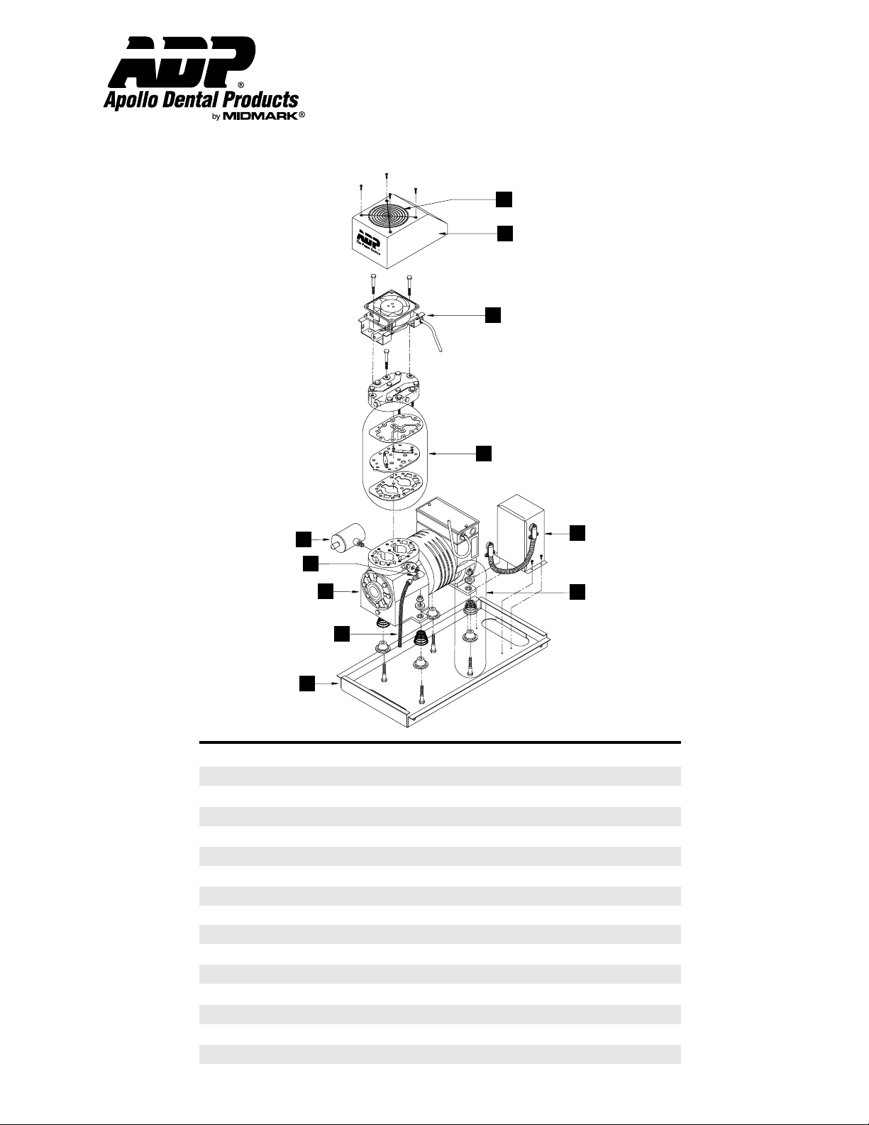
C. Organizer™ Compressor Components - Lubricated Models
Installation & Operation
Organizer™ Systems
Technical Service - (800) 233-4151
6
7
8
9
1
2
3
4
5
10
11
Item Description Quantity Part Number
1 Filter, Air Intake 1 ACP90500
2 Elbow, JIC 1/4” 1 PCB50100
3 Assy, Comp. Head Repl. 1 ACH95460
4 Hose, Flex 1 PCH50208
5 Tray, Compressor Mount 1 AAP95100
6 Guard, Fan 1 MMS70200
7 Shroud, Fan 1 ACP70205
8 Assembly, Fan 1 SEA95245
8a Fan 1 EMS10305
8b Bracket, Fan 2 MBS70102
9 Kit, Gasket and Valve Plate 1 HCA30629
10 Assembly, Capacitor Relay 1 SPD95291
10a Capacitor, Start 1 HCA30625
10b Capacitor, Run 1 HCA30622
10c Relay, Potential 1 HCA30655
11 Kit, Motor Mount 4 HCA30900
Page 11
AMI60900 Rev. 1/02
Page 12
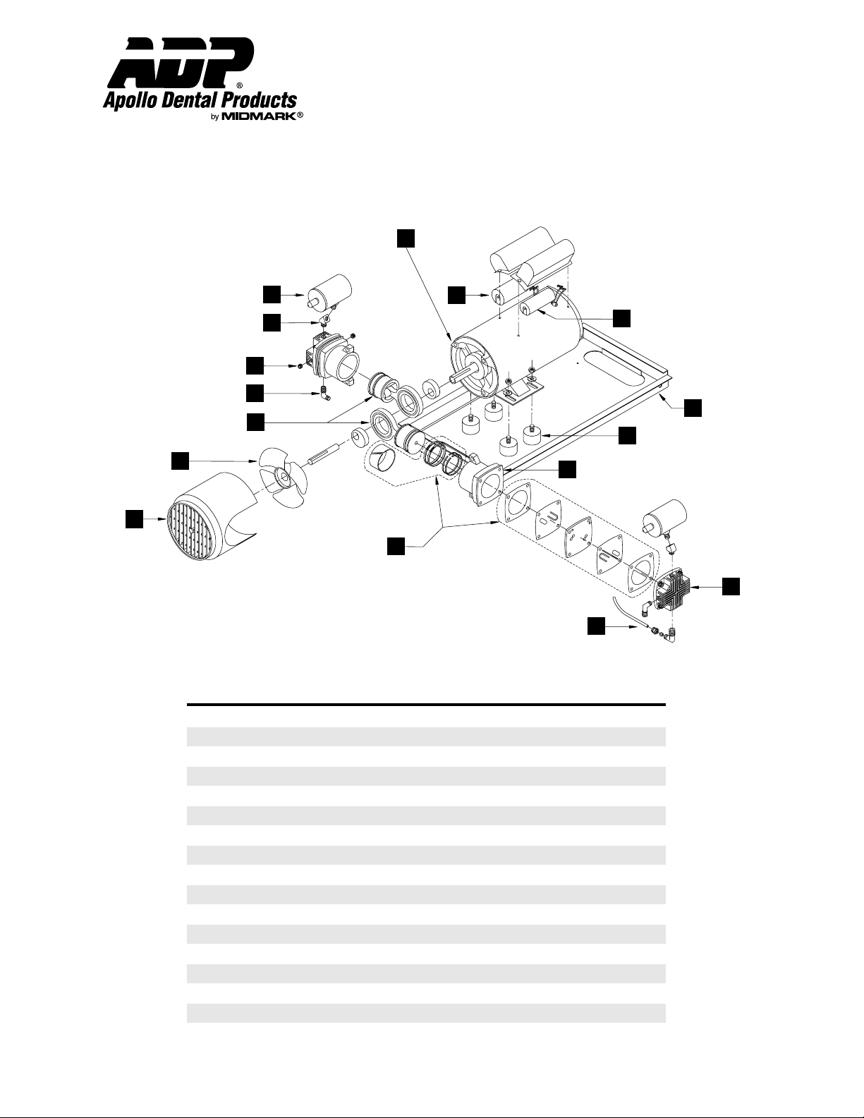
D. Organizer™ Compressor Components - Oil-less Models
1
Installation & Operation
Organizer™ Systems
Technical Service - (800) 233-4151
2
3
4
5
6
7
8
9
Item Description Quantity Part Number
16
15
14
13
12
11
10
1 Assembly, Replacement Head 1 HGH30210
2 Filter, Air Intake 2 ACP90500
3 Elbow, 45
4 Plug, Head Port 4 PCB50895
5 Elbow, 90
6 Assembly, Piston 2 HGA85415
7 Fan, Cooling 1 HGA10320
8 Shroud, Fan 1 HGA30300
9 Kit, Valve and Ring Replacement 1 HGA85325
10 Kit, Exhaust Air Crossover 1 HGA70920
11 Cylinder Head 2 HGA85107
12 Cylinder, Piston 2 HGA85102
13 Mount, Rubber Motor 4 MRP70980
14 Tray, Compressor Mount 1 AAP95100
15 Capacitor, Start 1 HGA85570
16 Capacitor, Run 1 HGA85575
O
O
Page 12 AMI60900 Rev. 1/02
2 PCB50628
2 PCB50404
Page 13
Installation & Operation
Organizer™ Systems
Technical Service - (800) 233-4151
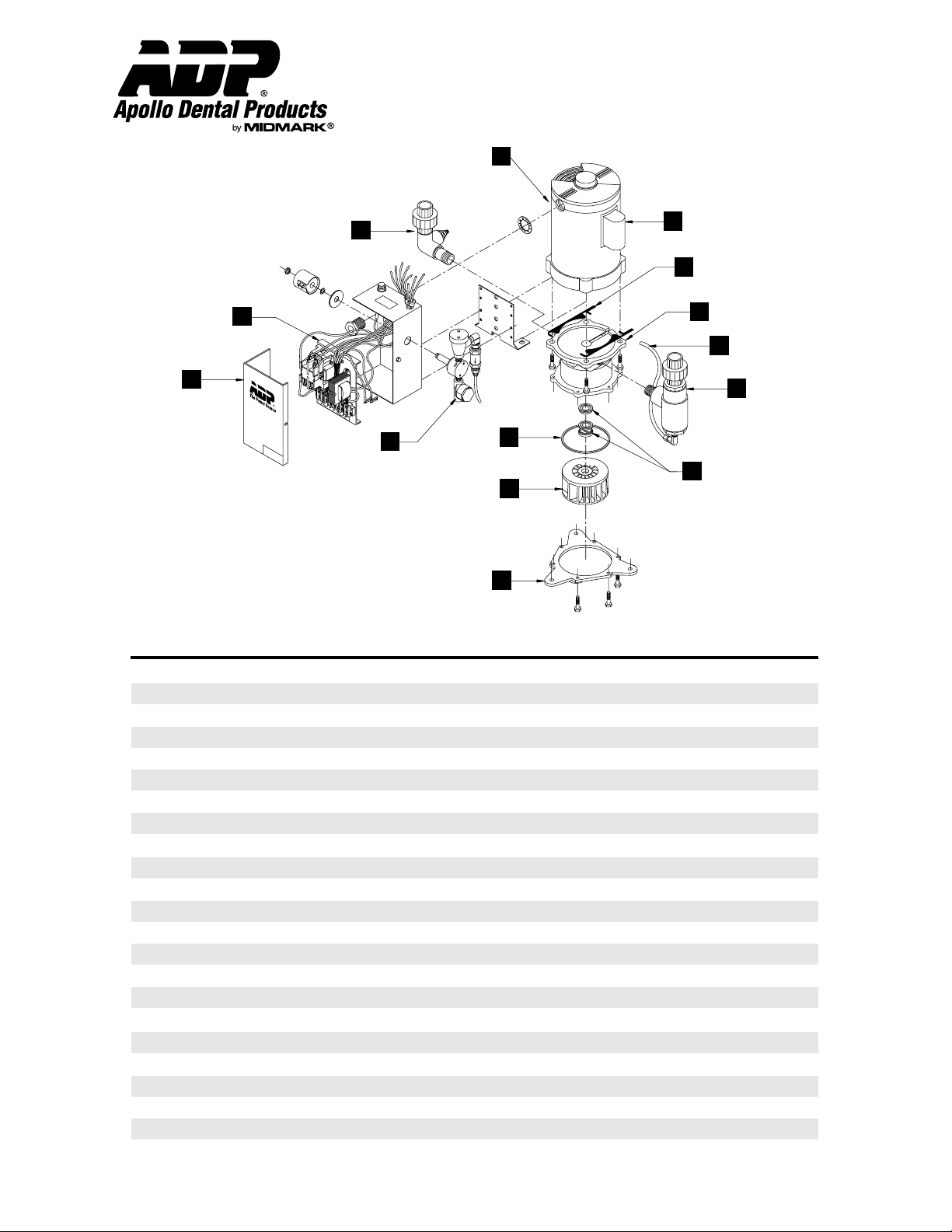
E. Organizer™ Vacuum Components
3
4
1
2
5
6
7
8
14
13
12
11
10
9
Item Description Quantity Classic Bronze Gold Series Ultra Vac
1 Replacement Pump 1 AVA95250 AVA95300 AVA95350
2 Manifold, Intake Assembly 1 AVP95850 AVP95850 AVP95850
3 Electrical Platform 1 SVA95830 SVA95830 SVA95830
3a Fuse, 1/2 Amp 1 EMS10930 EMS10930 EMS10930
3b Transformer 24V 1 ETR10500 ETR10500 ETR10500
3c Relay, 24V 1 ETR10460 ETR10460 ETR10460
3d Terminal Block 1 ECC10250 ECC10250 ECC10250
4 Cover, Electrical Box 1 ECB80561 ECB80561 ECB80561
5 Assembly, Water Solenoid 1 SVA95821 SVA95821 SVA95821
5a Strainer, 1/4” 1 PCB50960 PCB50960 PCB50960
5b Solenoid, 1/4” (w/Coil) 1 PVV10470 PVV10470 PVV10470
5c Coil, Solenoid 1 ECO10102 ECO10102 ECO10102
5d Valve, Anti-Siphon 1 PVV50595 PVV50595 PVV50595
5e Valve, Flow Regulator .19 GPM 1 PVV50505 PVV50505 PVV50505
6 ‘O’ Ring, Vacuum Base 1 MRP70955 MRP70955 MRP70955
7 Impeller, Vacuum 1 CVC80590 CVC80591 CVC80591
8 Baseplate, Vacuum 1 CVC80710 CVC80735 CVC80520
9 Seal, Vacuum Shaft 1 SVA95845 SVA95845 SVA95845
10 Recycler, Simple Solution 1 SVA95500 SVA95500 SVA95500
11 PolyFlow, Recycler 1 PCT80610 PCT80610 PCT80610
12 Housing, Vacuum Pump 1 CVC80705 CVC80730 CVC80500
13 Shim, Vacuum Pump 2 MMS71155 MMS71155 MMS71155
14 Motor, Electric Vacuum 1 HFM30905 HFM30905 HFM30905
Page 13 AMI60900 Rev. 1/02
Page 14
Installation & Operation
Clean or
replace
Does unloader
valve (G)
pressure
switch or
float assembly
(D) seat while
running?
Replace
intake filter
Defective
head,
contact
ADP
Is intake filter
(P) clogged?
Is there
sufficient
pressure
build-up with
head
discharge line
(O) removed?
NOTE:
Disconnect line
from bottom of
coalescing (D)
bowl for proper
diagnosis.
Turn valve
to "OFF"
position
Is manual
purge valve (Q)
in "ON"
position?
Locate and
repair
Are there leaks
in compressor
or in office
piping system?
Does air leak
from unloader
valve (G) or
pressure switch
continuously
until unit cycles
again?
Contact
ADP
Check
storage
check valve.
1. Ensure that
unloader valve (G),
float assembly (D)
& pressure switch
close on
pump-up, & open
on purge cycle.
2. Ensure that
drain line (I) is not
clogged
Does unloader
valve system
function
properly?
Does
compressor
run too hot or
too frequent?
Run unit in manual purge
mode for one week. If
indicator still wet, replace
desiccant (C).
1. Locate and
repair leaks
2. Ventilate if room
is above
100 deg F.
3. Contact ADP,
compressor may
be undersized.
Is the moisture
indicator (R) pink?
Does compressor
cycle with no air
being used?
Does compressor pressurize
from 80 to 100 psi in less
than 1 minute with no
air being used?
Does compressor run
for a few seconds,
"chuggs," then stops?
DOES
COMPRESSOR
RUN?
NOTE:
Close shut off
valve (A). Pump
up tank to 100 psi.
If pressure is
maintained for
15-20 min., leak is
in office lines.
Go to next
page
YES
YES
NO
YES
NO
YES
YES
NO
YES
YES
NO
YES
NO
YES
NO
NO YES
NO
NO
YES
NO
NO
NO
NO
YES
NO
NO
Is there excessive
oil usage?
NO
Is head (N)
level?
Does
compressor
run too hot or
too frequent?
YES
YES
NO
Contact
ADP.
Level head.
YES
NO
Locate
and repair
Is there a
blockage in the
air lines?
YES
YES
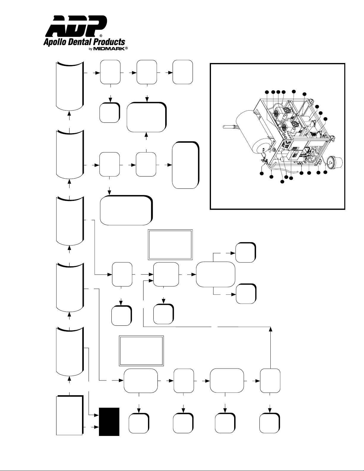
Compressor Component Diagram
A
B
E
F
C
D
G
H
I
J
M
N
K
L
O
P
Q
R
Organizer™ Systems
Technical Service - (800) 233-4151
Lubricated Compressor System
Trouble-Shooting Chart
™
Organizer
Page 14 AMI60900 Rev. 1/02
Page 15
Blockage in
air line,
locate &
repair
Install ADP
transformer
Does head run
with discharge
line (O)
disconnected?
Is there
sufficient
voltage at
disconnect
box?
NO
YES
NO
YES
NOTE:
Voltage should
be 10%
of rating.
Replace
defective
capacitors.
Is there
continuity
across terminal
2 & 5 of
potential relay?
NO
NO
NOTE:
1. Tap relay box,
if starts, relay
is bad.
2. Check for
continuity across
2 & 5, replace
if none.
Does motor run
after tapping
capacitor/relay
box, or
does start
capacitor feel
hot?
CHECK FOR:
1. Broken or loose
wire.
2. Defective pressure
switch.
3. Defective ON/OFF
switch.
4. Excessive voltage
drop across power
lines.
NO
YES
COMPRESSOR
DOES NOT RUN
OR RUNS FOR
ONLY A FEW
SECONDS
Go to
previous
page
NO
YES
+
-
Increase
room temp.
Is room
temperature
above 40 deg.
Fahrenheit?
NO
YES
Is there
sufficient
voltage at
motor terminals
"R" & "2"
when motor
tries to start?
Is there
resistance rise
across the
capacitors?
Is there
continuity
across the
thermal
protector?
Contact ADP,
head may
be frozen.
YES
YES
YES
NOTE:
Short capacitor
leads. Check
resistance rise. If
no resistance
rise, replace.
Replace
defective
thermal
protector.
NO
Replace
defective
potential
relay.
YES
NO
YES
YES
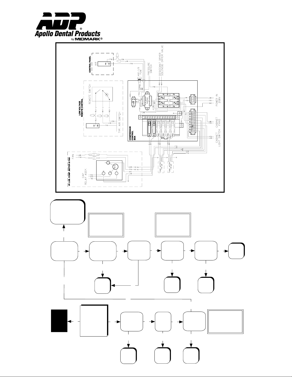
Compressor Wiring Diagram
Installation & Operation
Organizer™ Systems
Technical Service - (800) 233-4151
Lubricated Compressor System
Trouble-Shooting Chart
™
Organizer
Page 15 AMI60900 Rev. 1/02
Page 16
Clean or
replace
Does unloader
valve (G)
pressure
switch or
float assembly
(D) seat while
running?
Replace
intake filter
Defective
head,
contact
ADP
Is intake filter
(P) clogged?
Is there
sufficient
pressure
build-up with
head
discharge line
(M) removed?
NOTE:
Disconnect line
from bottom of
coalescing (D)
bowl for proper
diagnosis.
Turn valve
to "OFF"
position
Is manual
purge valve (Q)
in "ON"
position?
Locate and
repair
Are there leaks
in compressor
or in office
piping system?
Does air leak
from unloader
valve (G) or
pressure
switch or
coalescent filter
float (D)
continuously
until unit cycles
again?
Contact
ADP
Check
storage
check valve.
1. Ensure that
unloader valve (G),
float assembly (D)
& pressure switch
close on
pump-up, & open
on purge cycle.
2. Ensure that
drain line (I) is not
clogged
Does unloader
valve system
function
properly?
Does
compressor
run too hot or
too frequent?
Run unit in manual purge
mode for one week. If
indicator still wet, replace
desiccant (C).
1. Locate and
repair leaks
2. Ventilate if room
is above
100 deg F.
3. Contact ADP,
compressor may
be undersized.
Is the moisture
indicator (R) pink?
Does compressor
cycle with no air
being used?
Does compressor pressurize
from 80 to 100 psi in less
than 1 minute with no
air being used?
Does compressor run
for a few seconds,
"chuggs", then stops?
DOES
COMPRESSOR
RUN?
NOTE:
Close shut off
valve (A). Pump
up tank to 100 psi.
If pressure is
maintained for
15-20 min., leak is
in office lines.
Go to next
page
YES
NO
YES
NO
YES
YES
NO
YES
YES
NO
YES
NO
YES
NO
NO YES
NO
NO
YES
NO
NO
NO
NO
YES
Locate and
repair
Is there a
blockage in the
air lines?
YES
YES
NO
YES
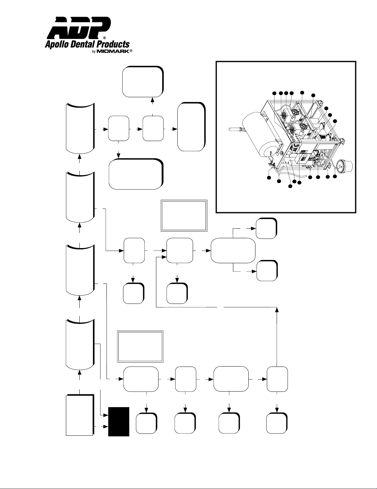
Compressor Component Diagram
NOTE: Lubricated Model Shown
A
B
E
F
C
D
G
H
I
J
M
N
K
L
O
P
Q
R
Installation & Operation
Organizer™ Systems
Technical Service - (800) 233-4151
Trouble-Shooting Chart
Oil-Less Compressor System
™
Organizer
Page 16 AMI60900 Rev. 1/02
Page 17
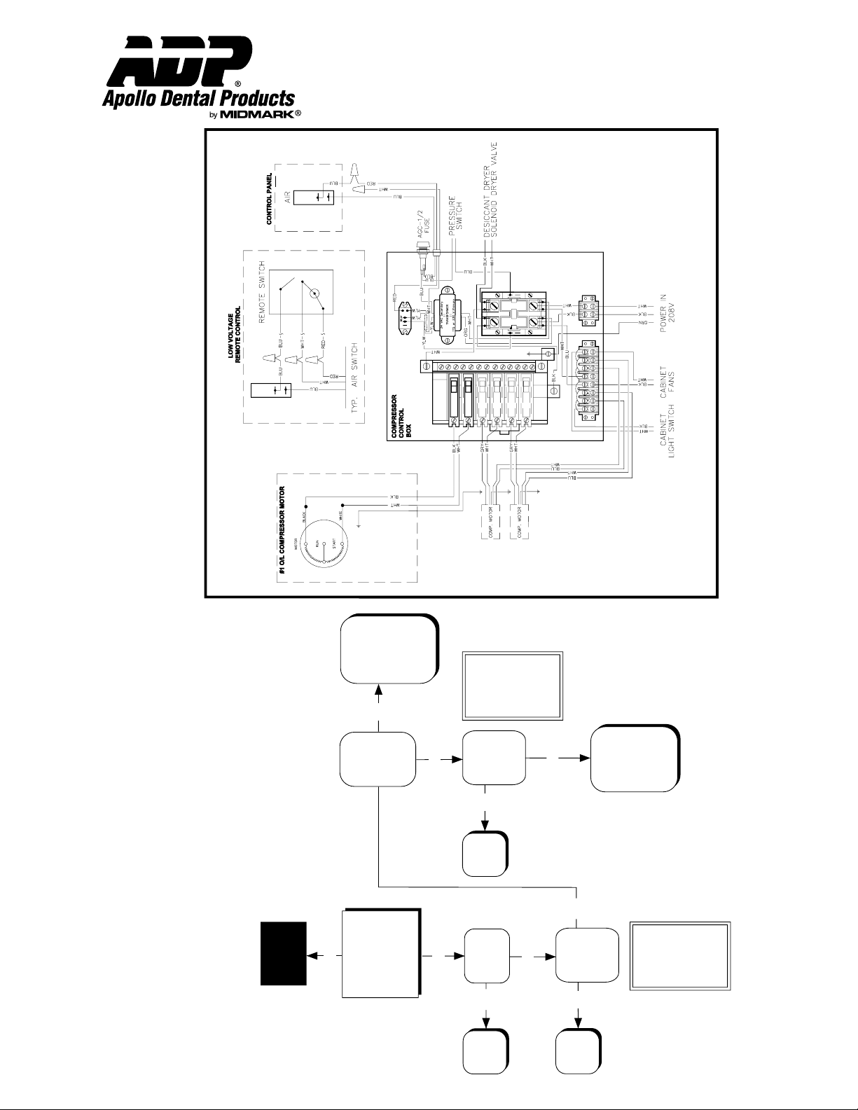
Installation & Operation
Blockage in
air line,
locate &
repair
Install ADP
transformer
Does head run
with discharge
line (O)
disconnected?
Is there
sufficient
voltage at
disconnect
box?
NO
YES
NO
YES
NOTE:
Voltage should
be 10%
of rating.
Replace
defective
capacitors
Is there
resistance rise
across the
capacitors?
NO
YES
NOTE:
Short capacitor
leads. Check
resistance rise. If
no resistance
rise, replace.
Is there
sufficient
voltage at
motor terminals
while motor
tries to start?
CHECK FOR:
1. Broken or loose
wire.
2. Defective pressure
switch.
3. Defective ON/OFF
switch.
4. Excessive voltage
drop across power
lines.
NO
Turn power off.
Remove fan guard.
Try turning fan by
hand. If it doesn't
turn, contact ADP,
head may be
frozen.
YES
COMPRESSOR
DOES NOT RUN
OR RUNS FOR
ONLY A FEW
SECONDS
Go to
previous
page
NO
YES
+
-
Organizer™ Systems
Technical Service - (800) 233-4151
Oil-Less Compressor System
™
Trouble-Shooting Chart
Organizer
Page 17 AMI60900 Rev. 1/02
Page 18
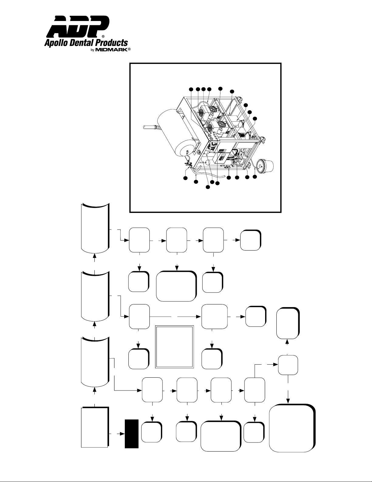
Installation & Operation
CHECK FOR:
1. Proper sealing of strainer
bowl (J). O-ring may be
pinched.
2. Proper fuctioning vacuum
relief valve (K). Valve may be
sticking open.
Clean or
replace
filter.
Is vacuum
relief filter
(K) clogged?
Adjust to
10" hg.
Is vacuum
relief valve (K)
set too high
(above 10" hg)?
Contact
ADP
Check usage chart
for maximum number
of simultaneous users.
Upgrade if necessary.
1. Check for
incorrectly sized
or defective
breaker.
2. Check for
proper wire
gauge size.
Does pump run intermittently?
Is there excessive vacuum?
Is there sufficient suction?
DOES
VACUUM PUMP
RUN?
Go to next
page
NO
YES
YES
NO
YES
YES
NO
YES
NO
NO
Does thermal
protector shut
the pump down?
Is circuit breaker
tripping?
NO
NO
Does relay (L)
contacts remain
closed?
Check for
adequete
ventilation.
YES
YES
Replace relay.
NO
Contact
ADP.
YES
Remove vacuum
inlet line from pump.
If there is good
suction at pump,
but little or none
in system, the system
is clogged or
contains leaks.
Are there any
vacuum leaks
at the pump?
Is the office
vacuum piping
system faulty?
NO
NO
NO
Is the vacuum
relief valve (K)
set too low
(normal level is
10" hg)?
Repair leaks.
YES
YES
Adjust to
10" hg.
YES
Is there
adequete
water supply
or water
pressure?
NO
Is intake strainer
screen (J)
clogged or is
swing check valve
(H) sticking?
Clean or
replace
filter.
YES
YES
NO
CHECK FOR:
1. "Open" water supply valve.
2. Clogged recycling line.
3. Clogged water strainer (M).
4. Clogged water regulator (M).
5. Check for proper voltage at
water solenoid coil (M) (115 VAC
on 1 & 1-1/2 hp, 230 VAC on
2 & 3 hp). Replace coil if proper
voltage exists.
YES
Compressor Component Diagram
A
B
E
F
C
D
G
H
I
J
M
N
K
L
O
P
Q
R
Organizer™ Systems
Technical Service - (800) 233-4151
™
Trouble-Shooting Chart
Vacuum System
Organizer
Page 18 AMI60900 Rev. 1/02
Page 19
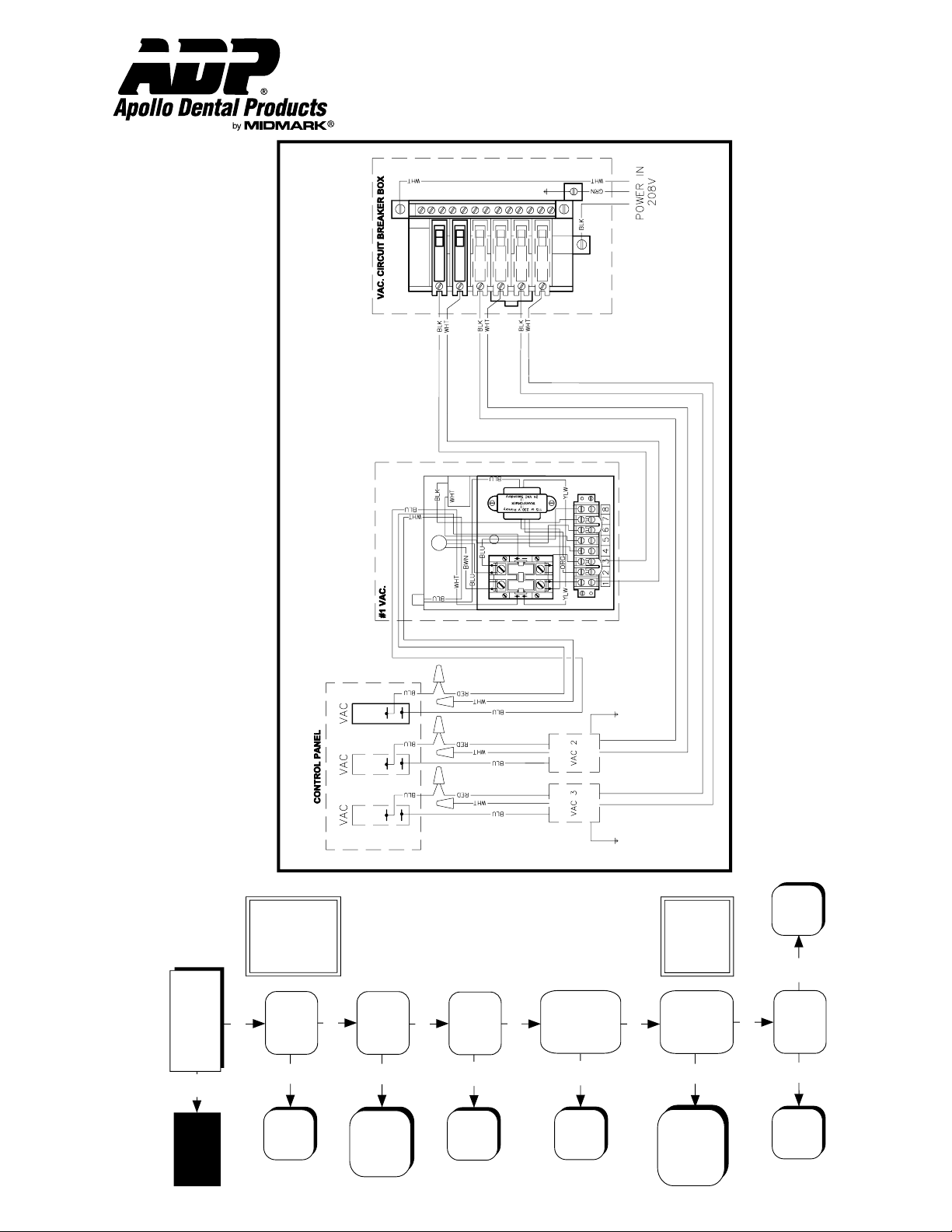
Check for broken
or loose power
line or excessive
voltage drop
across line.
Replace
remote switch
or replace
faulty wiring.
Is there proper
voltage at input
terminals (I)?
Does pump run
with remote
switching
bypassed (red &
blue low voltage
wires connected?
YES
NO
NO
YES
NOTE:
Voltage should
be 10% of rating.
Also, make sure
pump is jumpered
properly.
DOES VACUUM
PUMP RUN?
Go to
previous
page
YES
+
-
NO
Install ADP
transformer.
Is there sufficient
voltage at
disconnect box?
NO
Low voltage
or improperly
jumpered
pump.
Does relay
(L) chatter?
YES
YES
Is there sufficient
voltage at (20-28
VAC) between the
blue and white
low voltage
wiring?
NO
NO
Replace
relay.
Does relay (L)
contacts close?
NO
YES
Contact
ADP
YES
NOTE:
Make sure remote
switching is
bypassed.
Defective low
voltage circuit
breaker or
transformer or
faulty connection
within electrical box
Vacuum Wiring Diagram
Installation & Operation
Organizer™ Systems
Technical Service - (800) 233-4151
Vacuum System
™
Trouble-Shooting Chart
Organizer
Page 19
AMI60900 Rev. 1/02
Page 20

Installation & Operation
Organizer™ Systems
Technical Service - (800) 233-4151
Warranty Information:
• 2 Years - All Electrical Components
• 2 Years - Lubricated Compressor Heads
• 3 Years - Oil-Less Compressor Heads
• 2 Years - Classic Bronze™ Vacuum Pump Components
• 3 Years - Gold Series™ Vacuum Pump Components
• 5 Years - UltraVac™ Vacuum Pump Components
All ADP units are thoroughly inspected and tested in accordance with rigid specifications and standards. Our products are guaranteed
against any defective material and workmanship from the date of shipment; provided, that the installation, operation, and maintenance
is done in accordance with ADP procedures as outlined in our Installation and Maintenance Guides. Warranty cards must be returned
to ADP within ten days of installation to effect warranty. No other warranties or guarantees, expressed or implied are made.
ADP’s obligation under the warranty is to provide parts for the repair or, at its option, to provide the replacement product (excluding
labor). All special, incidental and/or consequential damages are excluded. We will not issue credit for complete air compressors or
vacuum systems without first attempting to correct the problem in the field. Written notice of breach of warranty must be given to ADP
within the warranty period. The warranty does not cove damage resulting form improper installation or maintenance, accident or
misuse. The warranty does not cover damage resulting from the use of cleaning, disinfecting or sterilizing chemicals and processes.
The warranty does not cover vacuum failures due to hard water deposits. Failure to follow instructions provided in ADP’s Installation
and Maintenance Guides may void the warranty.
Page 20
AMI60900 Rev. 1/02
 Loading...