

Page 1
INSTALLATION
INSTRUCTIONS
Table Of Contents
Unit Dimensions . . . . . . . . . . . . . . . . . . . . . . . . . . . . . . 2
Shipping . . . . . . . . . . . . . . . . . . . . . . . . . . . . . . . . . . . . 2
Optional Accessory . . . . . . . . . . . . . . . . . . . . . . . . . . . 2
CSA Requirements in USA . . . . . . . . . . . . . . . . . . . . . 2
CSA Requirements in Canada . . . . . . . . . . . . . . . . . . 3
Additional Requirements . . . . . . . . . . . . . . . . . . . . . . . 4
Unit Heater Installation . . . . . . . . . . . . . . . . . . . . . . . . . 4
Combustion and Ventilation Air . . . . . . . . . . . . . . . . . . 4
Venting . . . . . . . . . . . . . . . . . . . . . . . . . . . . . . . . . . . . . 4
Electrical Connections . . . . . . . . . . . . . . . . . . . . . . . . . 10
Typical Wiring Diagram . . . . . . . . . . . . . . . . . . . . . . . . 11
Gas Connectio n . . . . . . . . . . . . . . . . . . . . . . . . . . . . . . . . . 11
Leak Check . . . . . . . . . . . . . . . . . . . . . . . . . . . . . . . . . . . . 12
RETAIN THESE INSTRUCTIONS
FOR FUTURE REFERENCE
FSA
30,000 to 75,000 Btuh Series
LOW PROFILE UNIT HEATERS
IM-FSA-0653413-04
November 2011
Supersedes 065341303
Unit Start−Up . . . . . . . . . . . . . . . . . . . . . . . . . . . . . . . . . . . 12
To Turn Off Gas to Unit . . . . . . . . . . . . . . . . . . . . . . . . . . . . 13
Heating Sequence of Operations . . . . . . . . . . . . . . . . . . . . . 13
Ignition Control LE D . . . . . . . . . . . . . . . . . . . . . . . . . . . . . . 14
High Altitud e Adjustments . . . . . . . . . . . . . . . . . . . . . . . . . . 14
Gas Flow . . . . . . . . . . . . . . . . . . . . . . . . . . . . . . . . . . . . . . . 14
Gas Pressure Adjustments . . . . . . . . . . . . . . . . . . . . . . . . . 14
Limit Control . . . . . . . . . . . . . . . . . . . . . . . . . . . . . . . . . . . . 15
Louver Vane Adjustment . . . . . . . . . . . . . . . . . . . . . . . . . . . 15
Combustion Air Pressure Switch . . . . . . . . . . . . . . . . . . . . 15
Flame Rollout Switch . . . . . . . . . . . . . . . . . . . . . . . . . . . . . . 15
Service . . . . . . . . . . . . . . . . . . . . . . . . . . . . . . . . . . . . . . . . 15
Warranty . . . . . . . . . . . . . . . . . . . . . . . . . . . . . . . . . . . . . . . 18
WARNING
FIRE OR EXPLOSION HAZARD.
Failure to follow safety warnings exactly
could result in serious injury, death, or
property damage.
Be sure to read and understand the
installation, operation and service instructions in this manual.
Improper installation, adjustment, alteration, service or maintenance can cause
serious injury, death or proper t y dam age.
Do not store or use gasoline or other
flammable vapors and liquids in the vicinity of this or any other appliance.
Installation and serv ice m ust be p er-formed
by a qualified installer, service agency or
the gas supplier.
WHAT TO DO IF YOU SMELL GAS:
• Do not try to light any appliance.
• Do not touch any electrical switch; do not use
any phone in your building.
• Leave the building immediately.
• Immediately call your gas supplier from a
neighbor’s phone. Follow the gas supplier’s instructions.
• If you cannot reach your gas supplier, call the fire
department.
Page 2
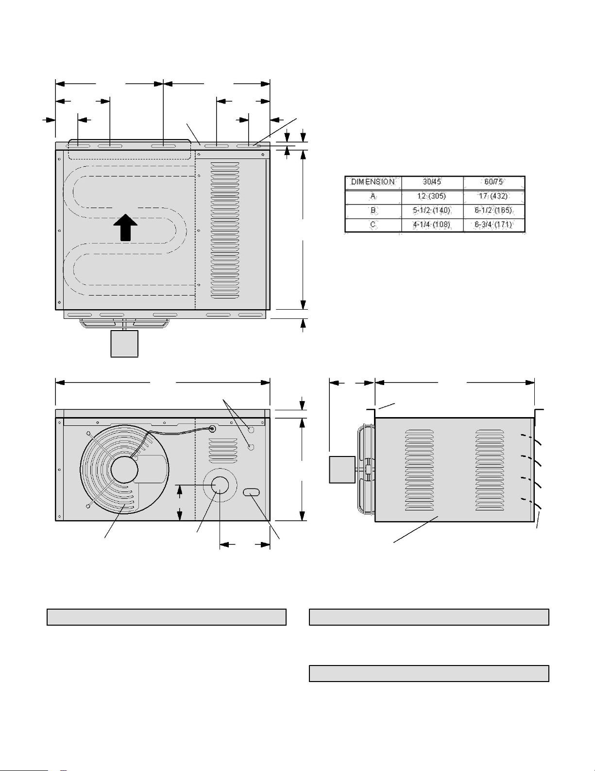
FSA UNIT DIMENSIONS
(NATURAL GAS & PROPANE)
(318)
(318)
6-1/2
6-1/2
(165)
(165)
2-3/4
HANGING
MOUNTING SLOTS (Typical)
BRACKETS (2)
5/16 x 3 Inches (8 x 76 mm)
(70)
(70)
1
(25)
1/2
(13)
AIR
FLOW
(470)
EXCHANGER
(ALUMINIZED
STEEL)
1
(25)
TOP VIEW
25
B
18-1/2
(635)
(470)
ELECTRICAL
1
HANGING
INLETS
(25)
BRACKETS (2)
A
C
FLUE
DIRECT
OUTLET
6
GAS
ACCESS
LOUVERS
DRIVE FAN
INLET
(152)
PANEL
2
12-1/2
HEAT
12-1/2
2-3/4
18-1/2
SERVICE
BACK VIEW SIDE VIEW
Shipping
Shipping contents includes heater, installation
instructions, warranty certificate, two mounting brackets
(shipped loose), and a flue transition. The heater is
shipped completely assembled. Check the unit for
shipping damage. The receiving party should contact the
last carrier immediately if any shipping damage is found.
Optional Accessory
FSA units require a changeover kit (165295204) when
the unit is to be used with LP/propane gas. The kit is
ordered separately.
CSA Requirements in USA
Installation of gas unit heaters must conform with local
building codes or, in the absence of local codes, with the
current edition of ANSI Z223.1, National Fuel Gas Code.
ADJUSTABLE
Page 3
Combustible materials that are affected by
Installation in aircraft hangers must be in accordance with
3
the current edition of ANSI/NFPA No. 409, Standard for
Aircraft Hangers.
Installation in parking st ructures m ust be in accordanc e
with the current edition of ANSI/NFPA No. 88A,
Standard for Parking Structures.
Installation in repair garages must be in accordance
with the current edition of ANSI/NFPA No. 88B,
Standard for Repair Garages.
These units are approved for residential garage or
non−confined living space applications. For installation in
a residential garage or non−confined living space, unit
must be installed so that burners and ignition source are
located no less than 18" (457mm) above floor. Heater
must be located or protected to avoid physical damage by
vehicles. Refer to the current edition of ANSI Z223.1,
National Fuel Gas Code.
Authorities having jurisdiction should be consulted
before installation. Air for combustion and ventilation
must conform to the methods outlined in the current
edition of ANSI Z223.1, Se ction 5. 3, Air for Com bustion
and Ventilation, or applicable provisions of local
building codes.
The National Fuel Gas Code (ANSI Z223.1) is available
from:
American National Standard Institute
These unit heaters are CSA International
design−certified. These unit heaters are certified for
installation to com bustible material as list ed in Table 1
and on unit rating plate.
Inc. 11 West 42nd Street
New York, NY 10036
Accessibility and s ervice clearances mus t be observed
in addition to fire protection clearances.
All electrical wiring and grounding for unit must be in
accordance with the regulations of the current edition of
ANSI/NFPA No. 70, National Electric Code.
The National Electric Code is available from:
National Fire Protection
Association 1 Batterymarch Park
PO Box 9101
Quincy, MA 02269−9101
CSA Requirements in Canada
These instructions are intended only as a general guide
and do not supersede local codes in any way. Authorities
having jurisdiction should be consulted before installation.
The installation must conform with local building codes or,
in the absence of local codes, with the
current edition of CSA-B149 installation compliance
codes. All electrical wiring and grounding for the unit
must also comply with the current edition of CSA
C22.1, Canadian Electrical Code.
These unit heaters ar e CSA−certified for the installation
clearances listed on the rating plate and in table 1.
Adequate clearance must be provided around the
appliance and around air openings into the com bustion
chamber. Provision shall be made for service
accessibility.
NOTE − Fire protection clearances may be exceeded
to provide additional space for service and accessibility.
GARAGE / WAREHOUSE INSTALLATIONS
1 − In a storage area, clearance from heaters to
combustible materials must be such that the
combustible material must not attain a
temperature above 160°F (71°C) by continuous
operation of the unit.
WARNING
exposure to temperatures LESS than 160°F
(plastics, plastic wrap, styrofoam, cardboard,
etc.) must be stored well away from this
heater. Discharge air temperatures for these
units can approach 200°F .
2 − Maintain an 8−foot (2m) minimum clearance from
the floor to the bot tom of the heater. Refer to th e
current edition of CSA-B149 for installation
compliance codes.
AIRCRAFT HANGER
1 − In an area where aircraft are house d or s erviced, a
10−foot (3m) minimum clearance from the highest
surface of the aircraf t to bottom of the heater mus t
be maintained.
2 − In other areas, an 8−foot (2m) minimum clearance
from the floor to bottom of heater must be
maintained.
3 − Heaters should be located so that they are
protected from damage from aircraft or other
appliances needed for servicing of aircraft. Refer
to requirements of the enforcing authorities.
RESIDENTIAL
These units are approved for residential garage or
non−confined living space applications. For installation in
a residential garage or non-confined living space, unit
must be installed so that burners and ignition source are
Page 4
Improper installation, adjustment, alteration,
agency or the gas supplier.
located no less than 18" (457mm ) above floor. Heater
MOUNTING
INSTALL UNIT HEATER
BRACKETS
(2)
SUPPORT
RODS
Combustion and Ventilation Air
CAUTION
Adequate facilities for supplying air for combustion and
ventilation
must
be provided
in accordance
with
the
current
edition
of
ANSI Z223.1, section
5.3
and
CSA−B149 installation compliance codes, or applicable
The appliance shall not be installed do wns tream from
All gas−fired appliances require air to be used for
evaporator coils or cooling units.
combustion. In man y buildings today, there is a negative
indoor
air
pressure
caused
by
exhaust fans, etc. If
sufficient quantities of combustion air are not available,
as shown in figure 1 or rotated 180° depending on desired
location as gover ned by clearances, vent connection, air
inefficient manner, resulting in incomplete combustion
direction,
gas
supply,
electrical supply
and
service
which can result in the production of excessive carbon
accessibility.
monoxide.
1 − If installing unit in a rotated position −−
Remove and retain screws securing door and rotate
CAUTION
door 180°. Resecure door using existing screws.
Rotate louvers to direct airflow as desired.
2 − Choose location for mounting brackets.
TABLE 1
UNIT CLEARANCES
Top
Side
Access Panel
Bottom
Back
Flue
in mm
in mm
in mm
in
mm
in mm in
mm
1 25
1
25
18 457 0
0
18
457 6
152
As with any mechanical eq uipment, personal injury
edges. Be careful when you handle this equipment.
Insufficient combustion air can cause headaches,
4
must be located or protec ted to avoid ph ysical damage
by vehicles. Refer to the current edition of CSA-B149
for installation compliance codes.
In a confined area, the heater must be installed in
accordance with the current edition of CSA-B149
installation compliance codes. Be sure to check with
local codes and ordinances for additional requirements.
Additional Requirements
The Commonwealth of Massachusetts stipulates the
following additional requirements:
1 − Gas furnaces shall be installed by a licensed
plumber or gas fitter only.
2 − The gas cock must be T handle" type.
Unit Heater Installation
WARNING
service or maintenance can cause property
damage, personal injur y or loss of l ife. Installation
and service must be performed by a licensed
professional installer (or equivalent), service
3 − Remove and retain three screws along top edge
(bottom edge when inverted) of front of unit.
4 − Align screw h oles on mounting bracket with hol es
along top edge (either upri ght or inverted) of unit.
Use existing screws to secure one mounting
bracket to front of unit. Secure other mounting
bracket to back of unit using screws provided in
bag assembly which contains flue transition.
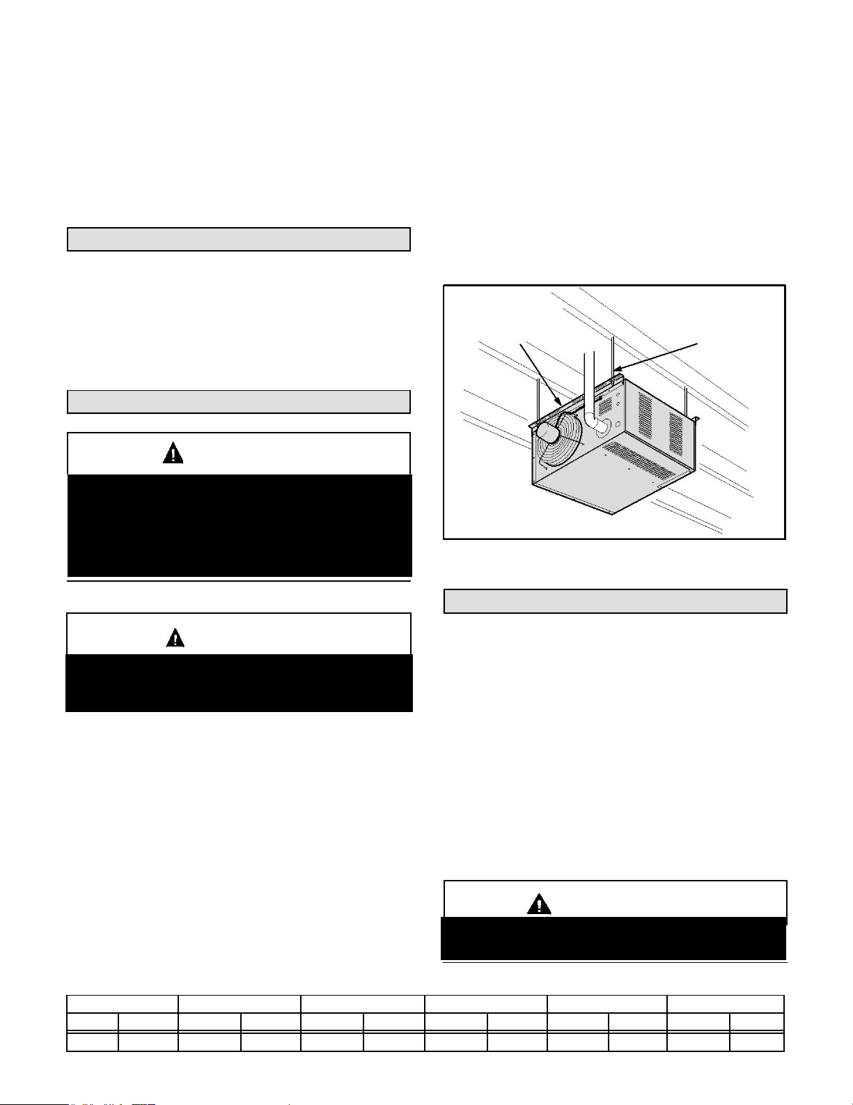
5 − To support unit, sec ur e mounting bracket to cei li ng
joist or truss. Unit may also be supported using
support rods as shown in figure 1.
FIGURE 1
can result from contact with sharp sheet metal
Unit is shipped ready for installation. Unit may be installed
provisions of local building codes.
the heater or another appliance will operate in an
nausea, dizziness, asphyxiation or death.
Page 5
If indoor air is to be used for combustion, it must be
Number. of
Feet
Meters
Elbows
25
2
20
6.1
15
4
10
3.0
5
5
free of the following s ubstances or the life of the heat
exchanger will be ad versely affected: c hlorine, carbon
tetrachloride, cleaning solvent, halogen refrigerants,
acids, cements and glues, print ing inks , fluorides, pa int
removers, varnishes, or any other corrosives.
Venting
NOTE − The vent is a passageway, vertical or near ly
so, used to convey flue gases from an appliance, or it s
vent connector, to the outside atmosphere. The vent
connector is the pipe or duct that connects a
fuel−gas−burning appliance to a vent or chimney.
NOTE − Local codes may supersede any of these
provisions.
GENERAL RECOMMENDATIONS AND
REQUIREMENTS
Unit heaters must be vented in compliance with the
latest edition of the National Fuel Gas Code (NFPA 54 /
ANSI Z223.1) in th e USA and with C SA-B149.1 codes
in Canada, as well as applicable provisions of local
building codes, and the following instructions.
A stamped/extruded metal transition is supplied
with this certified unit. It must not be modified or
altered and must be installed on the outlet of the
combustion air inducer assembly prior to the
installation of the vent connector. Failure to comply
with this requirement will void the certification of
the unit by the approval agencies.
A single-wall vent connec tor may be used between th e
furnace and the vertical vent pipe in all applications;
however, single−wall vent material cannot be used
for vertical vent piping in res idential applications.
UL−approved Category III venting materials must
be used in all residential applications which
include horizontal vent piping.
A single-wall vent pipe used as a vent connector in
residential or commercial applications, or as a vertical
vent in commercial applications, must have all seams and
joints sealed with pressure-sensitive aluminum tape or
silicone rubber sealant. Aluminum tape must meet the
provisions of SMACNA AFTS-100-73 Standards. The
aluminum tape must have a temperature rating of 400°F
(204°C). Silicone rubber sealant must have a temperature
rating of 482°F (250°C), i.e., Dow Corning
RTV−736 or equivalent.
All joints must be secured with at least two
corrosion−resistant screws. All joints must be checked for
gas tightness after installation. Single−wall vent pipe used
as vertical vent in commercial applications must not pass
through any attic, interior wall, concealed space, or floor.
VERTICAL VENTS USING METAL VENT PIPE –
COMMERCIAL & RESIDENTIAL INSTALLATIONS
These compact unit heaters are listed as Category 1
appliances for vertical vent installations.
1 − These unit heaters are to be used with NFPA− or
ANSI−approved chimneys or U.L.−listed type B−1
gas vents, or listed ch imney lin ing system s for gas
venting where applicable, as well as the
modifications and lim itation s listed in figur e 2. Sea l
single−wall vent material accor ding to General
Recommendations and Requirements section.
2 − The vent connector shall be 3" (76mm) diameter on
30K and 45K Btuh units and 4" (102mm) diameter on
60K and 75K Btuh units. In all cases, a flue transition
piece (supplied) is required to fit over the outlet of the
induced draft assembly on the appliance.
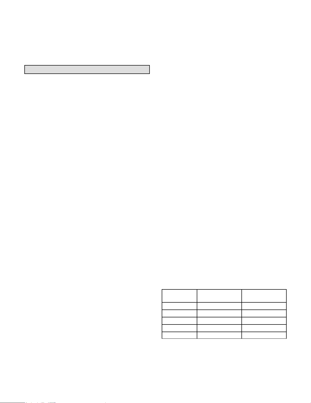
3 − Keep the vent connector runs as short as possible
with a minimum number of elbows. Refer to the
current edition of ANSI Z223.1 or
CSA-B149
installation compliance codes for maximum vent and
vent connector lengths. Horizontal run of the vent
connector from the combustion air inducer to the
chimney/vent cannot exceed the values in table 2.
Single−wall vent connector shall not be insulated.
4 − The entire length of a single-wall metal vent
connector shall be readily accessible for
inspection, cleaning and replacement.
MAXIMUM HORIZONTAL VENT CONNECTOR
AND HORIZONTAL VENT LENGTHS
1
3
5
TABLE 2
7.6
4.6
1.5
Page 6
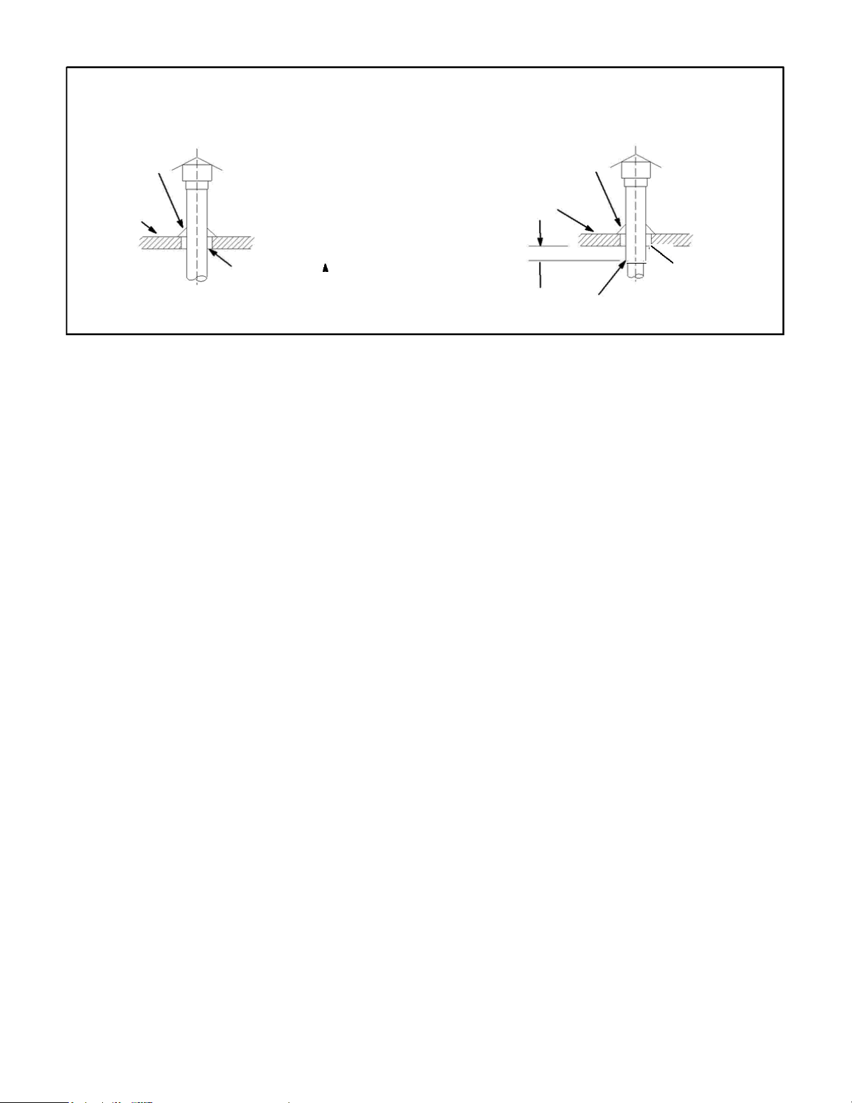
VENT TERMINATION ON SINGLE−WALL VERTICAL VENT RUNS
SINGLE−WALL VENT PIPE WITH SINGLE−WALL VENT PIPE WITH
SINGLE−WALL TERMINATION
DOUBLE−WALL (TYPE B−1) TERMINATION
6
(Commercial Applications Only)
ROOF FLASHING
ROOF PITCHED
FROM 0" TO 45"
2" CLEARANCE
THIMBLE
SEAL JOINT BETWEEN SINGLE−WALL VENT AND B" VENT TER-
MINATION AND THE OPEN SPACE BETWEEN THE SI N G L E W ALL
VENT PIPE AND THE OUTER PIPE OF THE B" VENT TERMINATION.
FIGURE 2
5 − The unit may be vented vertically as a single
appliance or in a common vent with other gas-fired
appliances. In common venting situations, vent
connectors for other appliances must maintain a 4"
(102mm) vertical separation between the vent
connectors. Refer to common venting tables in the
current editions of ANSI Z223.1 or CSA-B149
installation compliance codes for proper vent size.
6 − Clearance to combustible material is 6" (152mm) for
single−wall vent material except where a listed
clearance thimble is used. Clearance to combustible
material for type B−1 vent or factory−built chimney is
per manufacturer’s instructions.
7 − The vent connec tor sha ll b e support ed with out an y
dips or sags. Vertical vents shall be supported in
accordance with their listing and manufacturers’
instructions. All horizontal vent connector runs
shall have a slope up to the ver tica l v ent of at leas t
1/4" per foot (1mm per 50mm).
8 − All vertical type B-1 vents, single-wall vertical
vents (comm ercial applications), or listed chimney
lining systems m ust be term inated w ith a UL-listed
(or other equivalent agency) vent cap or liste d roof
assembly.
9 − The vent must extend at least 3 feet (1m) above
the highest point wh ere it pas ses through a roof of
a building. The vent must also extend at least 2
feet (1m) higher than an y part of a building within
a horizontal distance of 10 feet (3m) unless
otherwise specified by AN SI Z223.1 or CSA−B149
installation compliance codes. The vent must
extend at least 5 feet (2m) above the highest
connected equipment flue collar.
ROOF FLASHING
ROOF PITCHED
FROM 0" TO 45"
12" MAX
CLEARANCE TO BE
AS SPECIFIED ON
TYPE B" VENT PIPE.
HORIZONTAL VENTING
NOTE − Common venting is not allowed when
horizontally venting the unit heater.
If the FSA unit heater is to be horizontally vented, a
positive pressure ma y be created in the vent. The unit
heater, when installed with horizontal venting, will
perform as a category III appliance.
1 − In residential applications which include
horizontal venting, use only special vent
materials approved for use with Category III
appliances. Refer to table 3 for venting
components.
2 − The vent pipe diameter for horizontal installations
shall be 3" (76mm) on 30K and 45K Btuh units and
4" (100mm) on 60K and 75K Btuh units. In most
cases, a flue transit ion piec e (suppli ed) is requ ired
to fit over the outlet of the induced draf t assembly
on the appliance.
3 − The minimum horizontal vent length is 5 feet (2m).
4 − Refer to table 2 for maximum horizontal vent lengths.
5 − If possible, do not terminate the horizontal vent
through a wall that is exposed to prevailing wind.
Exposure to excessive winds can affect unit
performance. If such a termination is necessary,
use a wind block to protect the vent termination
from direct winds.
6 − Horizontal vent termination must be free from
obstructions and at least 12" (305mm) above
grade level and maximum snow height.
Page 7
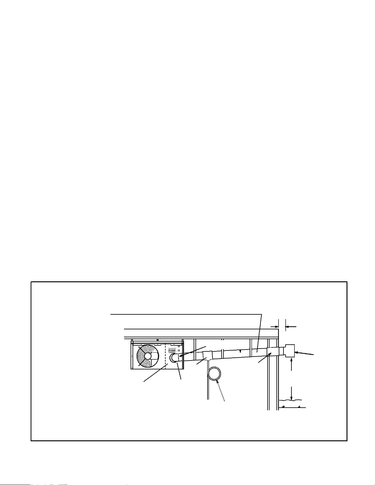
7 − Do not install a horizontal vent termination directly
COMMERCIAL APPLICATIONS
12 INCHES MIN.
−− Venting may be single−wall (26
(30.5 CM)
GSG) galvanized or equivalent
stainless steel vent pipe sealed
FLUE TRANSITION
VENT
per these instructions, OR listed
(PROVIDED)
TERMINATION
special vent for Category III
TEE
appliances.
SLOPE = 1/4 IN. PER FOOT
DRAIN LISTED WALL
RUN MAXIMUM.
TEE
THIMBLE
12" (30.5CM)
THROUGH
COMBUSTION
MINIMUM ABOVE
Category III adaptor
COMBUSTIBLE
HIGHEST SNOWFALL
AIR INDUCER
must be installed
WALL
before optio n al elb ow
(if used).
− Minimum horizontal vent length is 5 ft.
DRAIN LOOP (PROVIDED BY
INSTALLER WITH WATER TRAP
GROUND LEVEL
This does not include ter m ination tee. Refer to
TO CONDENSATE DRAIN
table 2 for maximum length and number of elbows.
7
below roof eaves or above a public walkway, or
any other area where condens ate dripping m ay be
troublesome and m ay cause some staining. Avoid
windows where steam may cause fogging or ice
buildup.
8 − Minimum clearance for horizonta l vent termination
from any door, window, gravity air inlet, gas or
electric meter, regulator s , and rel ief equi pment is 4
feet (1m) for United States installations.
In Canada, horizontal vent termination must have
a minimum 6-foot horizontal clearance from gas
and electric meters and relief devices.
Refer to latest editions of the ANSI Z223.1 or
CSA−B149 for installation compliance codes and
with local authorities with jurisdiction.
9 − Vent termination must be a minimum of 4 feet
(1m) below, or 4 feet (1m) horizontally, from any
soffit or under−eave vent.
10 − Vent must be a minimum of 6 feet (2m) from an
inside corner formed by two exterior walls. If
possible, leave a 10−foot (3m) clearance.
11 − Vent termination must be a minimum of 10 feet
(3m) from any forced air inlet (includes fresh air
inlet for other appliances, such as a dryer).
12 − When termination is routed through combustible
wall, vent termination must be supported using a
firestop to maintain clearances specified on unit
rating plate. Inside edge o f vent termination must
be at least 12" (305mm) from outside wall.
13 − All horizontal vents which use special vent pipe for
use with Category III appliances must terminate
with an approved Category III tee. Opening end
must face downward.
14 − For horizontal venting, the vent pipe shall be
supported with hangers no more than 3 feet (1m)
apart to prevent movement after installation.
15 − Select a wall termination point that will maintain
1/4" (6mm) rise per foot (305mm) slope of
horizontal run of vent pipe.
16 − For upward sloped vent, a condensate tee and
drain must be instal led within the first 5 feet (2m )
from the unit heat er to protect the appliance. If a
flexible condensate drain line is used, the drain
line must include a loo p fil led with water to pre vent
combustion products fr om entering the s tructur e. If
the unit is shut down for an extended period of
time and will be exposed to sub-freezing
temperatures, the condensate may freeze.
17 − Select a wall termination point that will maintain
1/4" rise per foot slope of horizontal run of vent
pipe. In areas where autho rities having jurisdict ion
permit, a downward slope of maximum 1/4" per
foot is also accepta ble. Condensate drai nage can
be collected in a tee pipe section (figure 4) with
drain loop similar to one used for upward slope
vent, or allowed to drip through the vent
termination, if permitted by authorities (figure 5).
CONDENSATE DRAIN THROUGH TEE PIPE AND DRAIN LOOP
UPWARD SLOPE ON HORIZONTAL VENT −− RESIDENTIAL OR COMMERCIAL APPLICATION
RESIDENTIAL APPLICATIONS
−− Venting must be listed special
vent for Category III appliances.
NOTE
COMMON VENTING NOT ALLOWED WHEN HORIZONTALLY VENTING T HE UNIT HEA TE R.
FIGURE 3
Page 8
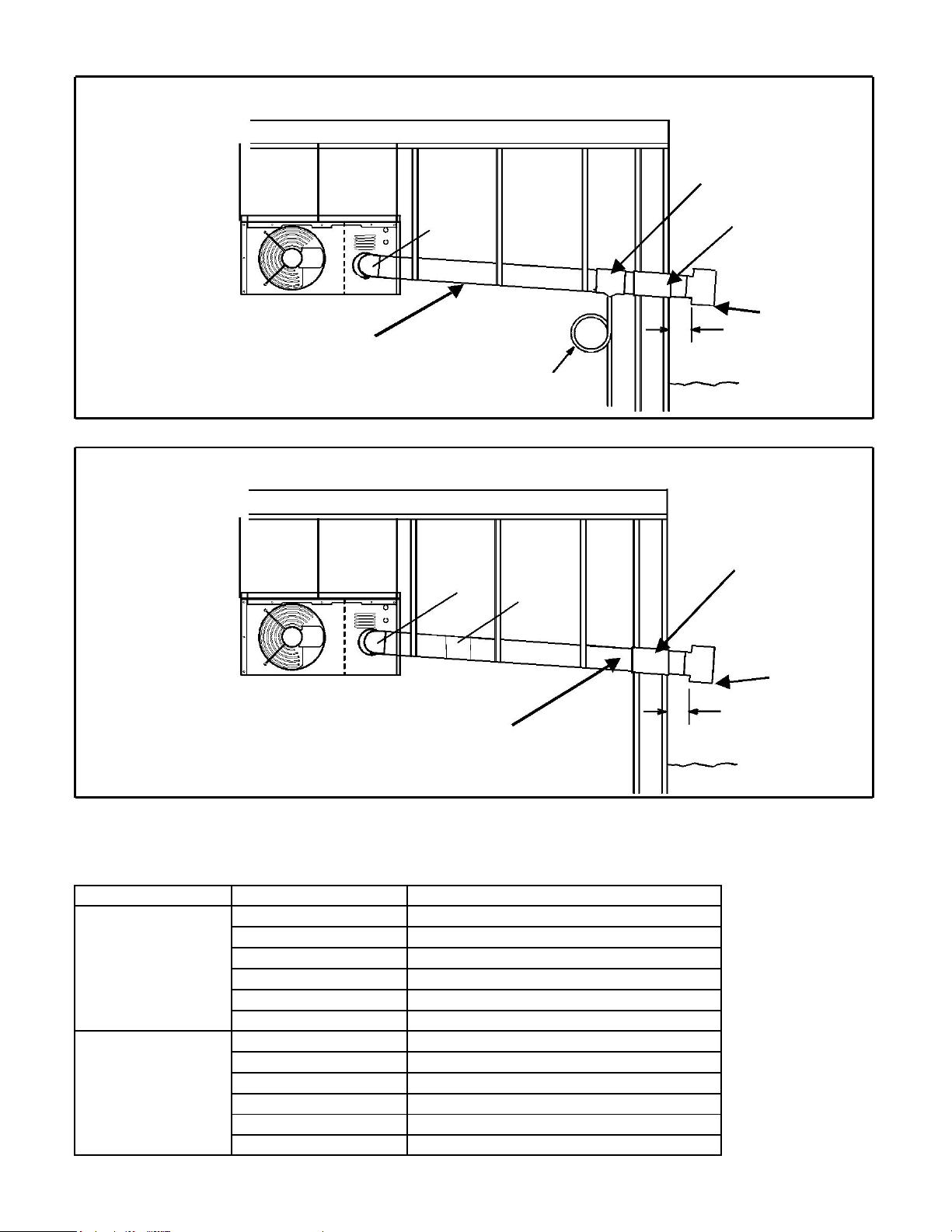
NOTE − Minimum
CONDENSATE DRAIN THROUGH TEE PIPE AND DRAIN LOOP
−
horizontal vent length is
DOWNWARD SLOPE ON HORIZONTAL VENT − RESIDENTIAL OR COMMERCIAL APPLICATION
5 ft. This does not
include termination tee.
Refer to table 2 for
Category III
maximum length and
adaptor must
DRAIN TEE
number of elbows.
be installed
before
LISTED THIMBLE
optional
COMMON VENTING
THROUGH
elbow
COMBUSTIBLE
NOT ALLOWED WHEN
(if used).
WALL
HORIZONTALLY
VENTING THE
UNIT HEATER.
RESIDENTIAL AP PL ICATIONS −− Venting must be
VENT
TERMINATION
listed special vent for Category III appliances.
TEE
single−wall (26 GSG) galvanized or equivalent
WATER TRAP TO
MIN. (30.5 CM)
stainless steel vent pipe sealed per these instructions,
CONDENSATE DRAIN
OR listed special vent for Category III appliances.
(Provided by installer)
SLOPE = 1/4 IN. PER FOOT RUN MAXIMUM.
CONDENSATE DRAIN THROUGH VENT TERMINATION
DOWNWARD SLOPE ON HORIZONTAL VENT−RESIDENTIAL OR COMMERCIAL APPLICATION
NOTE − Minimum
horizontal vent length is
5 ft. This does not
include termination tee.
DOUBLE
Refer to table 2 for
LISTED THIMBLE
MALE
maximum length and
THROUGH ELBOW
ADAPTER
number of elbows.
COMBUSTIBLE
COMMON VENTING
kits only)
WALL
NOT ALLOWED WHEN
HORIZONTALLY
VENTING THE UNIT
HEATER.
VENT
TERMINATION
RESIDENTIAL AP PL ICATIONS −− Venting must be listed special vent
for Category III appliances.
COMMERCIAL APPLICATIONS −− Venting may be single−wall (26
12 INCHES
GSG) galvanized or equivalent stainless steel vent pipe sealed per
MIN. (30.5 CM)
these instructions, OR listed special vent for Category III appliances.
SLOPE = 1/4 IN. PER FOOT RUN MAXIMUM.
Unit
Part Number
Description
66808901
3" upward sloped Cat III vent kit
66809001
3" downward sloped Cat III vent kit
FSA*−30
66809101
3" 90° elbow Cat III (optional)
FSA*−45
66809201
3" straight pipe (length = 6")
66809203
3" straight pipe (length = 36")
66808902
4" upward sloped Cat III vent kit
66809002
4" downward sloped Cat III vent kit
FSA*−60
66809102
4" 90° elbow Cat III (optional)
66809302
4" straight pipe (length = 12")
66809303
4" straight pipe (length = 36")
8
COMMERCIAL APPLICATIONS −− Venting may be
DRAIN LOOP WITH
FIGURE 4
OPTIONAL
(Cat. III
12 INCHES
FIGURE 5
Category III Horizontal Venting Components
FSA*−75
(Required for Horizontal Vent Applications)
66809202
66809301
TABLE 3
3" straight pipe (length = 12")
4" straight pipe (length = 6")
TEE
Page 9
Single appliance venting of a fan-assisted unit
9 installation
compliance codes.
VENTING USING A MASONRY CHIMNEY
9
The following additional requirements apply when a
lined masonry chimney is being used to vent the
compact unit heater.
IMPORTANT
heater into a tile lined masonry chimney (interior
or outside wall) is prohibited. The chimney must
first be lined with either type B-1 vent or an
insulated single−wall flexible vent lining system,
sized in accordance with venting tables in the
ANSI Z223.1, or CSA-B14
1 − Masonry chimneys used to vent Category I units
heaters must be either tile−lined or lined with a listed
metal lining system or dedicated gas vent. Unlined
masonry chimneys are prohibited. A category I
appliance must never be connected to a chimney that
is servicing a solid fuel appliance. If a fireplace
chimney flue is used to vent this appliance, the
fireplace opening must be permanently sealed.
2 − A fan−assisted unit heater may be commonly vented
into an existing lined masonry chimney provided:
a. The chimne y is currently serving at least one
3 − A B-1 double−wall vent or masonry chimney liner
4 − Do not install a manual dam per, barometric draft
5 − If type B -1 double-wall vent is used inside a
6 − Insulation for the flexible vent pipe must be an
7 − The space between liner and chimney wall should
8 − If B-1 vent or an insulat ed flex ible v ent pi pe cannot
draft−hood equipped appliance.
b. The vent connector and chimney are size d in
accordance with venting tables .
shall terminate above th e roof s urface with a list ed
cap or a listed roof assembly in accordance with
the terms of their res pective listings and the vent
manufacturer’s instructions.
regulator, or flue restr ictor between t he unit heater
and the chimney.
chimney, no other appliance can be vented into
the chimney. Outer wall of type B-1 vent pipe must
not be exposed to flue products.
encapsulated fiberglass sleeve recommended by
the flexible vent pipe manufacturer.
NOT be insulated with puffed mica or any other
loose granular insulating mater ia l.
be used as liners, the chim ney must be rebuilt to
accommodate one of these methods or some
alternate approved m ethod must be found to vent
the appliance. When inspection reveals that an
existing chimney is not safe for the intended
purpose, it shall be reb uilt to conform to nationally
recognized standards, lined or relined with suitable
materials or replaced with a gas vent or chim ney
suitable for venting unit heaters. The chimney
passageway must be checked periodically to
ensure that it is clear and free of obstructions.
REMOVAL OF UNIT FROM COMMON VENT
In the event that an existing unit heater is removed from
a venting system commonly run with separate gas
appliances, the vent ing system is likely to be too lar ge
to properly vent the remaining attached appliances. The
following test should be conducted while each
appliance is in oper ation and the other appliances ar e
not in operation, yet remain connected to th e common
venting system. If the venting system has been
installed improperly, the system must be corrected.
1 − Seal an y unused openings in the comm on venting
system.
2 − Visually inspect the venting system for proper size
and horizontal pitch. Determine there is no blockage
or restriction, leakage, corrosion, or other
deficiencies which could cause an unsafe condition.
3 − In so far as is practical, close all building doors and
windows and all door s bet ween t he s p ac e i n which
the appliances remaining connected to the
common venting system are located and other
spaces of the building. T urn on clothes dryers and
any appliances not connected to the common
venting system. Turn on any exhaust fans, such
as range hoods and bathroom exhausts, so the y
will operate at maximum speed . Do not operate a
summer exhaust fan. Close fireplace dampers.
4 − Follow the lighting instructions. Plac e t he a ppl ia nce
being inspected in operati on. Adjust therm ostat so
appliance will operate continuously.
5 − Test for spillage at the draft hood relief opening
after five minutes of main burner operation. Use
the flame of a match or cand le, or smok e from a
cigarette, cigar, or pipe.
6 − After it has been determined that each appliance
remaining connected to the common venting
system properly vents when tested as outlined
above, return doors, windows, exhaust fans,
fireplace dampers and any other gas-burning
appliance to their previous condition of use.
7 − If improper venting is observed during any of the
above tests, the comm on venting system must be
corrected. The comm on venting syst em should be
resized to approach the minimum size as
determined by using the appropriate tables in
Appendix G in the current editions of the ANSI
Z223−1, or the appropriate Category I Natural Gas
and Propane appliances venting sizing tables in
the current standards of the CSA-B149 for
installation compliance codes.
Page 10
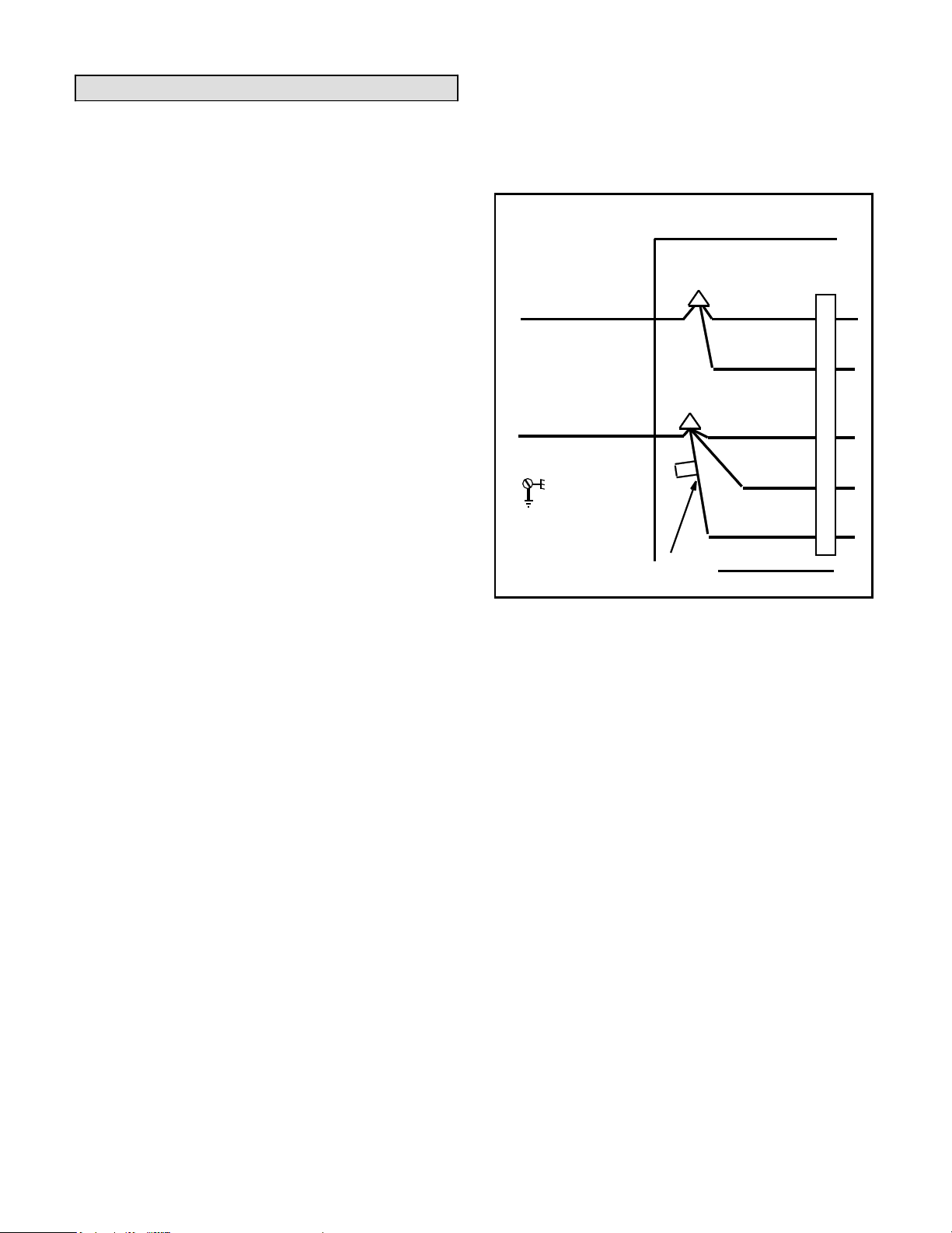
FIGURE 7
LINE VOLTAGE FIELD WIRING
L1
WHITE
WHITE
BLACK WIRE WITH WHITE TAPE OR
WHITE WIRE WITHOUT TAPE
N
BLACK
UNIT
BLACK
EQUIPMENT
GROUND
10
Electrical Connections
NOTE − Local codes may supersede any of the
provisions outlined in this instr uc tion.
The FSA series unit heaters use a direct spark ignition
system. There is no pilot necessary as the spark lights the
main burner as the gas valve is turned on. The direct
spark ignition control board emits radio noise as the
sparking process is under way. The level of energy may
be sufficient to disturb a logic circuit in a microprocessor
controlled thermostat. It is recommended that an isolation
relay be used when connecting the unit heaters to a
microprocessor controlled thermostat. Install the
thermostat according to instructions provided. Install a
separate fused disconnect switch, with the fuse sized
according to blower motor size. Connect wiring through
knockout on the junction box located on the side of the
unit heater. Refer to heater wiring diagram for connection
information. Use 18 gauge wire or larger for thermostat
connections.
NOTE − Electrically ground unit in accordance with
local codes or, in the absence of local codes, in
accordance with the c urrent ed itions of the ANSI/NF PA
No. 70, National Electrical Code or CSA C22.1,
Canadian Electrical Code, Part 1.
NOTE − Uninsulated ground wires must be wrapped in
electrical tape to avoid damage to the electrical system.
Make line voltage connections as shown in figure 7.
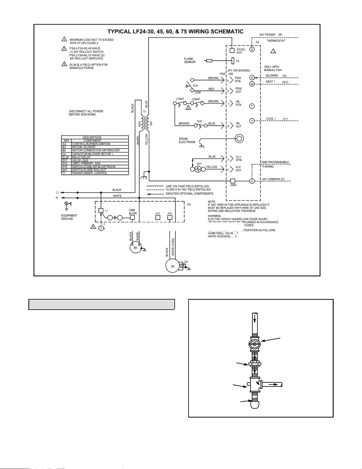
Connect field wiring as shown on wiring diagram on
unit. Also refer to typical diagram in this manual. An
additional thermostat wire must be run to terminal G" on
heater when continuous blower is desired.
Page 11
GAS SUPPLY CONNECTION
MAIN SHUT−OFF VALVE
(Furnished by Installer)
GROUND
JOINT UNION
1/8 NPT
PLUGGED
GAS FLOW
TAP
DRIP LEG
11
TYPICAL FSA WIRING SCHEMATIC
Gas Connection
When connecting gas sup p l y, the len gth of the r u n f r om
the meter must be c onsidered in determining the p ipe
size to avoid exc essive pressure drop. A line pressure
of 7" w.g. (178mm w.g.) for natural gas should be
maintained when sizing piping. For correct sizing of
piping, consult the utility having jurisdiction.
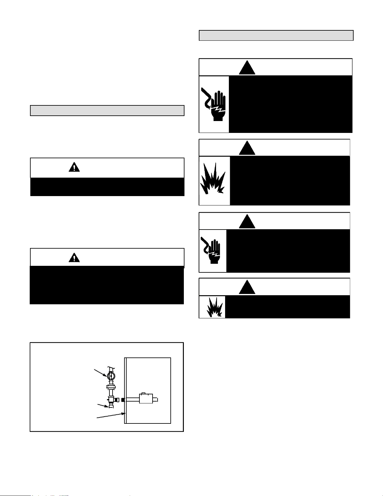
A drip leg should be insta lled in the vertical pipe run to
the unit. In some localities, codes may require that a
manual main shutoff valve and union (furnished by
installer) be installed external to the unit. Union must
be of the ground joi nt type. A drip le g shoul d be readi ly
accessible to perm it cleaning and emptying. See figure
8.
MANUAL
FIGURE 8
Page 12
DO NOT use matches, candles, flame or other
sources of ignition to check for gas leaks.
The heater and its individual shut off valve must
See figure 9.
NOTE − If a switch box is mounted over electrical
MANUAL MAIN SHUT −OFF
DISCONNECT GAS
VALVE WILL NOT HOLD
VALVE WHEN TEST
NORMAL TEST
PRESSURES OF
PRESSURES OF 1/ 2 p sig
(3.45kPa) OR HIGHER
OR HIGHER WILL
BE USED.
CAP
UNIT HEATER
12
knock−outs on back of unit, leave a minimum of 4"
(102mm) clearance between switch box and drip leg.
A 1/8" NPT plugged tap s hall be installed immediately
upstream of the gas supply connection to the heater.
NOTE − Compounds used on threaded joints of gas
piping must be resistant to the actions of liquefied
petroleum gases.
Leak Check
After gas piping is com pleted, carefull y check all pip ing
connections, (field and factory), for gas leaks. Use a
soap solution or other preferred means.
CAUTION
The appliance must be isolated from the gas supply
piping system by closing its individual manual gas
shutoff valve during any pressure testing of the gas
supply system at test pressures equal to or less than
1/2 psig (3.45kPa).
IMPORTANT
be disconnected from the gas supply piping
system during any pres sure testi ng of that s ystem
at test pressures in excess of 1/2 psig (3.45kPa).
NOTE − In case emergency shutdown is required, shut
down main gas valve and disconnect main power to unit.
These devices should be properly labeled by the installer.
GAS SUPPLY TO UNIT HEATER
1/2 psig (3.45kPa)
FIGURE 9
Unit Start−Up
FOR YOUR SAFETY READ BEFORE LIGHTING
! WARNING
Electric shock hazard. C an caus e injur y or
death. Do not use this heater if any part
has been under water. Im mediately call a
qualified service techn ician to in-spect t he
furnace and to replace any part of the
control system and any ga s con-tr ol which
has been under water.
! WARNING
Danger of explosio n. Can cause injury or
product or property damage. If overheating occurs or if gas supply fails to
shut off, shut off the m anual gas valve to
the appliance before shutting off electri-cal
supply.
Electric shock hazard. C an cause injury or
death. Before attempting to perform any
service or maintenance, turn the electrical
power to unit OFF at d is connec t switch(es).
Unit may have multiple power supplies.
Danger of explosion and fire. Can cause
injury or product or property damage. You
must follow these instructions exactly.
BEFORE LIGHTING smell all around the appliance
area for gas. Be sur e to sm ell next to the floor b ecause
some gas is heavier than air and will settle on the floor.
Use only your hand t o push in or turn the gas control
knob. Never use tools. If the knob will not push in or
turn by hand, do not try to repair it, call a qualified
service technician. Force or attempted repair may result
in a fire or explosion.
FSA unit h eaters are equ ipped with an autom atic spark
ignition system. There is no pilot. In case of a safety
shutdown, move therm ostat switch to OFF, then retur n
the thermostat switch to HEAT position.
! WARNING
! WARNING
Page 13
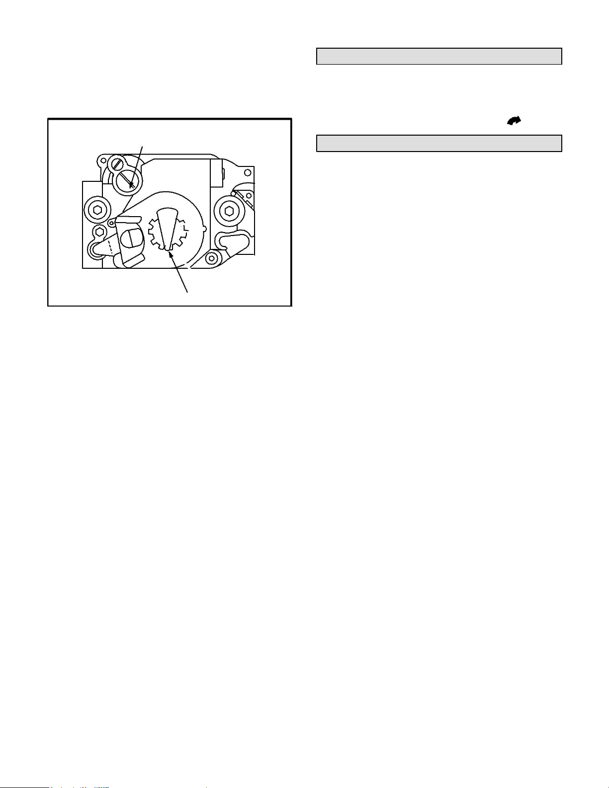
OPERATION OF HONEYWELL VR8205 SERIES GAS
GAS VALVE SHOWN IN OFF POSITION
FIGURE 10
2 − Turn off all electrical power to appliance.
3 − This appliance is equipped with an ignit ion de vice
which automatically lights burners. DO NOT
attempt to light the burners manually.
4 − Turn the manual knob on gas valve clockwise to
OFF. Do not force.
5 − Wait five minutes to clear out any gas. If you then
STOP!
gas supplier from a neighbor’s phone. Follow the
gas supplier’s instructions. If you do not smell
gas, go to next step.
6 − Turn manual knob on gas valve counterclockwise to
ON.
7 − Turn on all electric power to unit.
8 − Set thermostat to desired setting.
9 − The combustion air inducer (CAI) will start. The
burners will light within 40 seconds.
10 − If unit does not light first time (gas line not fully
purged) it will attempt up to two more ignitions before
locking out.
12 − If appliance still will not operate, follow the
instructions “To Turn Off Gas to Unit" and call
your service technician or gas supplier.
13
VALVE (FIGURE 10)
NOTE − STOP! Read the safety information at the
beginning of this section.
1 − Set thermostat to lowest setting.
HONEYWELL VR8205 SERIES GAS VALVE
MANIFOLD PRESSURE ADJUSTMENT SCREW
ON
OFF
smell gas,
11 − If lockout occurs, repeat steps 1 through 9.
Immediately call your
To Turn Off Gas to Unit
1 − Set thermostat to lowest level.
2 − Turn off all electrical power to unit if ser vice is to
be performed.
3 − Turn knob on gas valve 90° clockwise to OFF.
Heating Sequence of Operation
1 − When the thermostat calls for heat, the
combustion air inducer starts immediately.
2 − Combustion air pressure switch proves inducer
operation before allowing power to the ignition
controller. This switch is factory set and no
adjustment is necessary.
3 − After pre−purge of approximately 30 seconds, the
spark ignition is energi zed and the solen oid valves
open in the gas valve.
4 − The spark then ignites the gas, the ignition sensor
proves the flame and the combustion process
continues.
5 − In the event that th e f lame is not detec ted after the
first 10−second trial for ignition, the controller will
repeat steps 3 and 4 an additional two times
before locking out the gas valve. Ignition control
will then automatically repeat steps 3, 4, and 5
after 60 minutes.
NOTE − To interrupt the 60−minute lockout period,
move thermostat from Heat" to OFF" then back to
Heat." Heating sequence then restarts at step 1.
6 − The burners must light without noticeable crossover
delay. There must be no flame lifting from the burner
heads, flashback or burning within the burner. The
flames should be predominantly blue in color and
should be approximately centered in the tubes with
no apparent impingement taking place.
7− The ignition control will energize the fan
approximately 45 seconds after ignition is
established.
8 − After the thermostat demand is satisfied the gas
valve is closed. Five seconds after the demand is
satisfied, the combustion air inducer is shut off.
9 − The ignition control will shut off the system fan
approximately 150 secon ds after the gas valve is
de-energized.
Page 14
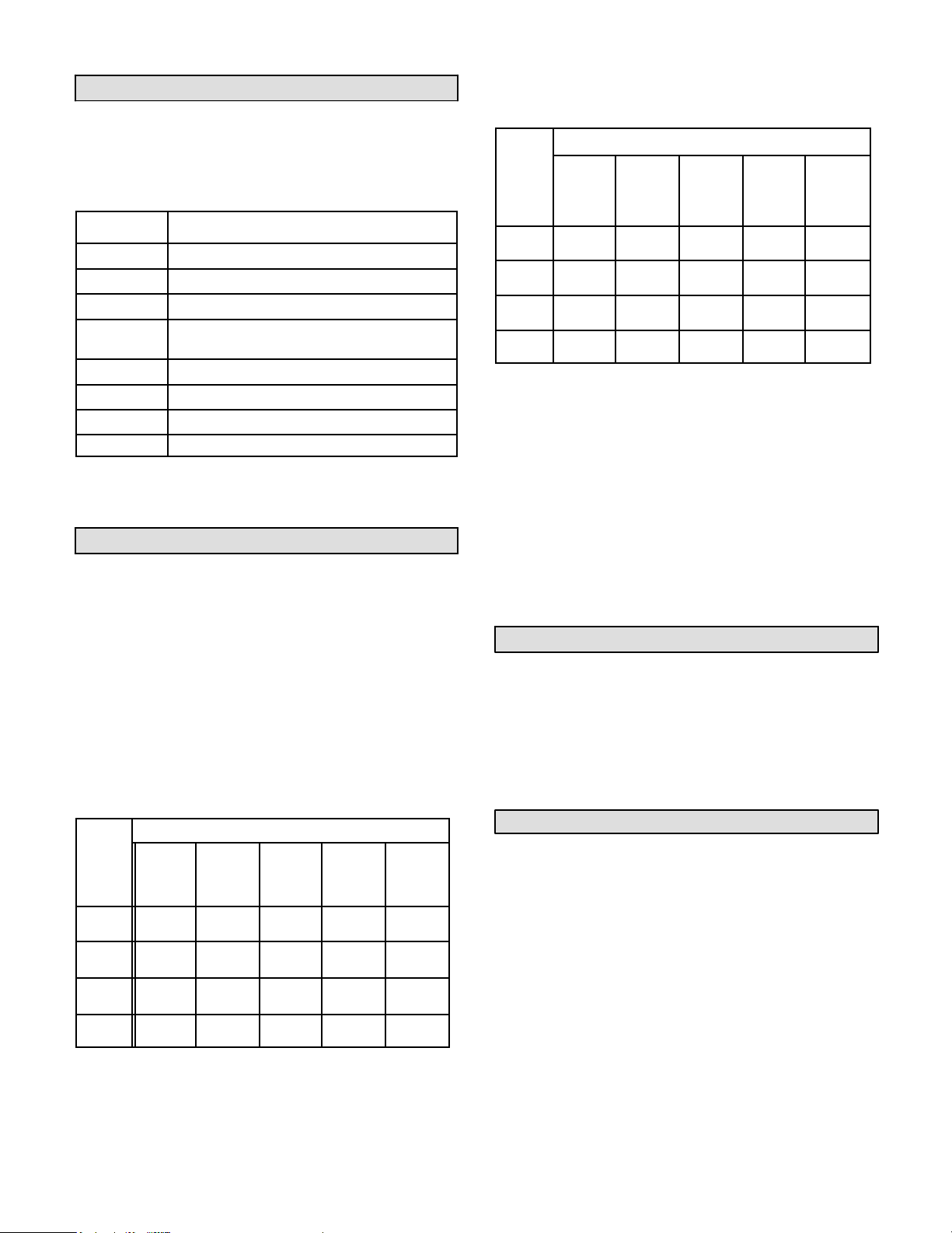
LED
UNIT OPE RATION
Slow. Flash* Normal Operation − No call for heat
Fast Flash
Normal Operation − Call for heat
2 Flashes
System lockout − failed to detect or sustain flame
3 Flashes
Pressure switch failed closed before CAI is ener-
gized or failed open after CAI is energized
4 Flashes High limit or rollout sw itch open
5 Flashes
Flame sensed and gas valv e not energized
Steady On
Ignition control failure
Altitude in Feet (Meters)
INPUT
0−3500
35−4500
45−5500
55−6500
65−7500
(BTUH)
(0− (1067−
(1372−
(1676−
(1981−
1067)
1372)
1676)
1981)
2286)
30
3.5 3.5 3.5 3.5 3.5
(0.87)*
(0.87)*
(0.87)*
(0.87)*
(0.87)*
45
3.5 3.5 3.5 3.5 3.4
(0.87)*
(0.87)*
(0.87)*
(0.87)*
(0.85)
60
3.5 3.5 3.5 3.5 3.5
(0.87)*
(0.87)*
(0.87)*
(0.87)*
(0.87)*
(0.87)*
(0.85)
(0.82)
(0.80)
(0.77)
Altitude in Feet (Meters)
INPUT
3501 −
4501 −
5501 −
6501 −
(BTUH)
0−3500
4500
5500
6500
7500
(0 −1067)
(1067−
(1372−
(1676−
(1981−
1372)
1676)
1981)
2286)
30
9.5 9.5 9.5 9.5 9.5
(2.37)*
(2.37)*
(2.37)*
(2.37)*
(2.37)*
45
(2.37)*
(2.37)*
(2.37)*
(2.37)*
(2.28)
9.5 9.5 9.5 9.5 9.5
(2.37)*
(2.37)*
(2.37)*
(2.37)*
(2.37)*
75
9.5 9.2 8.9 8.6 8.3
(2.37)*
(2.28)
(2.21)
(2.13)
(2.06)
14
Ignition Control LED
The ignition control contains a green LED which indicates
the following:
Steady Off
IGNITION CONTROL LED
TABLE 4
Loss of Power
*When thermostat is placed in continuous fan mode LED will
slowly flash.
High Altitude Adjustments
Units may be fired at full in put up to 2000 feet. (610m)
above sea level. Above 2000 feet (610m), manifold
pressure must be adjusted on some units. Adjust
pressure regulator to pressure shown in table 5 for
natural gas and table 6 for LP/propane gas.
NATURAL GAS MANIFOLD PRESSURES
75
3.5
TABLE 5
[inch w.g. (kPa)]
3.4
3.3
3.2
3.1
*No adjustment required.
TABLE 6
LP/PROPANE GAS MANIFOLD PRESSURES
60
*No adjustment required.
NOTE − A natural to LP/propane gas changeover kit
is required to convert unit. Refer to the installation
instructions supplied with the changeover kit for
conversion procedure.
9.5
[inch w.g. (kPa)]
9.5
9.5
9.5
If unit is installed at an a ltitude greater than 7500 feet
(1372m), unit m ust be derated by four perc ent for each
additional 1000 feet (305m) above 7500 feet or as
specified by local authority having jurisdiction.
The combustion air inducer proving switch is factory
set. No adjustment is necessary.
Gas Flow
To check for proper gas flow to the combustion chamber,
determine the Btu input from the appliance rating plate.
Divide this input rating by the Btu per cubic feet of
available gas. Result is the required number of cubic
feet per hour. Determine the flow of gas through the
gas meter for two m inutes and m ultipl y by 30 to g et the
hourly flow of gas.
Gas Pressure Adjustment
1 − Check gas line pressure with unit firing at
maximum rate. A m inimum of 5" (127mm ) w.g. for
natural gas or 10.4" (264mm) w.g. for LP/propane
gas should be maintained for proper unit
operation.
2 − After line pressure has been checked and
adjusted, check regulator pressure. Correct
manifold pressure is shown on the unit rating
plate. See figures 9 and
10 for gas pressure adjus tment screw location. A
natural gas to LP/propane gas changeover kit is
required to convert the unit in the field. Refer to
installation instructions provided with changeover
kit for conversion procedure.
9.2
Page 15
Turn off gas and electrical power to unit before
forming any maintenance or service
operation after service or maintenance
Limit Control
15
The limit control switch is factory-set and is not
field−adjustable.
Louver Vane Adjustment
Rotate louver vanes to direct airflow upward,
downward, straight, or any combination of these
directions. When unit is installed in an inverted position,
louvers may be positioned in the same manner.
Combustion Air Pressure Switch
This pressure switch chec ks for proper combustion air
inducer operation bef ore allowing an ignition tria l. The
switch is factory−set. No field adjustment is necessary.
Flame Rollout Switch
The flame rollout switch(es ) are located on the burner
box top, behind the ignition control board. This normally
closed switch opens on a temperature rise. Check for
adequate combustion air before manually resetting
switch.
Service
CAUTION
peroperations on this unit. Remember to follow
lighting instructions when putting unit back into
The unit heater and vent system shall be inspected
once a year by a licensed professional service
technician, or equivalent.
1 − Periodically examine burner flames for proper
appearance during the heating season.
2 − Before each heating season examine the burners for
any deposits or blockage that may have occurred.
3 − Clean burners as follows:
a − Turn off both electrical and gas supplies to unit.
b − Disconnect gas supply piping, high tension
and sensor leads. Remove gas manifold.
Remove burner tray.
BURNERS
c − Clean burners as necessary. Make sure that
burner heads line up prope rly to ensure flam e
crossover. Check spark gap on electr ode and
adjust if required. The gap should be betwee n
0.110" and 0.140" (3mm to 4mm). The gap
may be checked with appropriat ely sized t wist
drills or feeler gauges.
d − Reinstall burner tray, gas manifold, high
tension and sensor leads. Reconnect gas
supply piping.
e − Restore electrical power and gas supply.
Follow lighting instructi ons to light unit. Check
burner flame.
FLUE PASSAGEWAY AND FLUE BOX
The flue passages and flue box should be inspected
and cleaned prior to each heating season. The
sequence of operation should be as follows:
1 − Turn off both electrical and gas supply to unit.
2 − Disconnect combustion air inducer wiring.
3 − Rem ove screws sec uring flue box to unit. Remove
flue box. If necessary, remove inducer assembly
from flue box. Clean flue box with wire brush.
4 Remove turbulator retention bracket and
turbulators. Clean turbulators with wire brush.
5 − Remove burners as described in Burners" section.
6 − Clean tubes with a wire bru s h.
7 − Reassemble unit. The combustion air and flue box
gaskets should also be replaced during reassembly.
8 − Restore electrical power and gas supply. Follow
lighting instructions to light unit. Check operation
of unit.
COMBUSTION AIR INDUCER
Under norm al operating conditions, the combustion air
inducer should be checked and cleaned prior to the
heating season with the power supply disconnected.
Use a small brush to clean inducer wheel.
1 − Check all wiring for loose connections.
2 − Check for correct voltage at unit (unit operating).
3 − Check amperage draw.
ELECTRICAL
FLUE AND CHIMNEY
Check all vent and vent connec tor joints for tightness.
Ensure that connections are sealed and that there are
no blockages.
FAILURE TO OPERATE
If unit fails to operate check the following:
Page 16

1 − Is thermostat calling for heat?
16
2 − Is main disconnect closed?
3 − Is there a breaker tripped or a fuse
blown? 4 − Is gas turned on at meter?
5 − Is manual shutoff valve open?
6 Is unit ignition s ystem in lock out? If unit l ocks out
again, call service technician to inspect unit.
7 − Is pressure switch closed? Obstructed flue will
cause unit to shut off at pressure switch. Check
flue passage and outlet.
The safety shut−off valve test procedure is as follows:
1 − Turn off the manual gas valve.
2 − Set the thermostat to call for heat.
3 − System begins normal sequence of operation.
4 − After approximately 30 sec onds ( pr e p urge p er io d)
SAFETY SHUT−OFF VALVE TEST
the LED will fast flash indicating the gas valve is
powered.
5 − Af ter 10 seconds, the gas valve closes and steps
4 and 5 will repeat two additional times before
locking out the gas valve, which will be indicated
by two flashes on the LED.
6 − T o res tart the s ystem , de−energize the thermostat
call for heat and follow th e operating instructions
under Unit Start−Up and Operation.
REPAIR PARTS
When ordering repair parts, include the complete unit
model number listed on the unit rating plate. For
example: FSAN-45-1-1-1.
Page 17
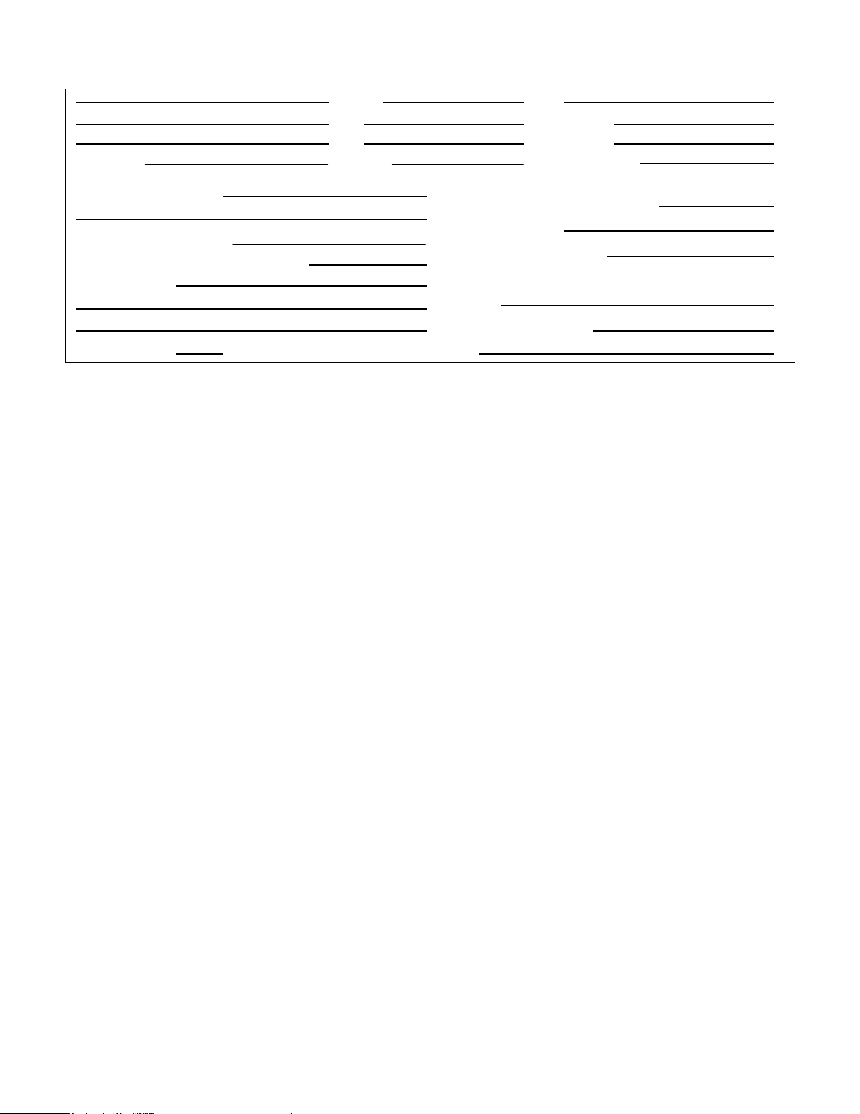
Job Name:
Job No.:
Date:
Job Location:
Installer:
Unit Model No.:
Serial No.:
Service Technician:
Supply Voltage
Flue Connections Tight?
Blower Motor Lubrication O.K.?
Fan Timer Operation Checked?
Gas Piping Connections Tight & Leak−Tested?
THERMOSTAT
Blower Motor Amps
Furnace Btu Input
Calibrated?
Heat Anticipator Properly Set?
Line Pressure
17
START−UP AND PERFORMANCE CHECKLIST
City:
City:
State/Province:
State/Province:
Electrical Connections Tight?
Manifold Pressure
w.c.
Air Shutters Properly Adjusted (If Installed)?
Level?
Page 18
18
Unit Heater Limited Warranty – Standard 2 Year
(Applies only to product installed within the United States or Canada)
Term of Warranty: Advanced Distributor Products (ADP) warrants that products sold shall be of
merchandisable qualit y, free of def ects in m aterial and workm anship, under nor mal use and s ervice, for a pe riod
of two (2) years from the date of installation, not
Extended Components: This warranty provides extended c overage on Aluminized Heat Ex changers for ten
(10) years and Stai nles s St eel H eat Ex changers for fifteen (15) years. The extended warrant y cov er ag e be gins
with the installation date an d represents the total warr anty period f or the specif ic component. ADP, at its option ,
will furnish a replacem ent heat exchanger or allo w a credit (in the amount of the heat exchanger origin al selling
price) toward the purc hase of a new ADP unit heater. No extended cov erage granted for HED ser ies heat
exchangers.
Warranty Procedure: Warranty parts should be replaced by a qualified local contractor or dealer and will
require the following information: model num ber, serial num ber, date of installation a nd an accur ate descript ion
of the problem. Contractor or dealer will contact a local ADP distributor for replacement parts.
Replacement Parts: If, during the term of this warranty, a warranted part f ails, ADP will either provide a
replacement part free of c harge, or may at its option, grant a credit for the origin al pur c hase pr ice of the defective
article to a distr ibut or of ADP products. AD P may require the return of a defective article f or f ac tory inspection to
verify and/or determine the root cause of the f ai lure . Covered components inc l ude all p ar ts of this uni t ex c ept f or
the following excluded components, which are not covered by this warranty: cabinet, cabinet p iec es, wiring and
wiring harnesses.
to exceed three (3) years from the date of manufacture.
Care of Equipment: For this warranty to apply, ADP product must be properly installed, operated, and
maintained in accordanc e with the installation, opera tion and maintenance instr uctions provided with eac h unit.
Unauthorized alteration of ADP product may void this warranty.
Conditions of Warranty: Replacement parts furnished under th is warrant y will be warran ted for the ba lance of
the original warrant y term of the unit (including any extended w arranty) and wi ll not serve to extend the ori ginal
term. This warran ty is void if the ADP pr oduct is rem oved from the origina l installation s ite. This warrant y does
not apply to damage caused by shipping, misuse, mishandling or damage caused by floods, winds, fires,
lightning, or exposure to corrosive elements/environments (such as salt, chlorine, fluorine or other damaging
chemicals).
Limitations of Warranty: The costs of m iscellaneous m aterial and labor char ges for dia gnost ics, s ervic ing or
replacing parts are not covered. ADP shall have no liability for expenses incurred for repairs without prior,
written authorization from ADP.
The foregoing is in lieu of all other warranties, express or implied, not withstandi ng the prov isions of the Uniform
Commercial Code, the Magnuson-Moss W arranty-Federal Trade Commission Improvement Act, or any other
statutory or common law, federal or state.
ADP makes no warranty, express or implied, of fitness for any particular purpose, or of any other nature
whatsoever, with respect t o products manufactured or sold by ADP here under, except as specifically set forth
above and on the fac e hereof. It is expressl y understood and agreed that ADP shall not b e liable to buyer, or
any customer of buyer, for direct or indirect, special, incidental, consequential or penal damages, or for any
expenses incurred b y reason of the use or m isuse by buyer or third par ties of said produc ts. To the extent s aid
products may be considered “consumer products”, as defined in Sec. 101 of the Magnuson-Moss W arrantyFederal Trade Commission Improvement Act, ADP makes no warranty of any kind, express or implied, to
“consumers,” except as specifically set forth above on the face hereof.
2175 West Park Place Boulevard
Stone Mountain, Georgia 30087
www.adpnow.com
Page 19

19
Page 20
 Loading...