

ADMTK ADM8211 Datasheet

A
ADM8211
IEEE802.11b WLAN NIC Solution
PCI/miniPCI/Cardbus Interface w i th M AC Unit +
Baseband Processor (BBP)
DATASHEET
Rev. 1.1
Feb, 2003
Information in this document is provided in connection with ADMtek products. ADMtek may make changes to
specifications and product descriptions at any time, without notice. Designers must not rely on the absence or
characteristics of any features or instructions marked "reserved" or "undefined." ADMtek reserves these for future
definition and shall have no responsibility whatsoever for conflicts or incompatibilities arising from future changes to
them.
The products may contain design defects or errors known as errata, which may cause the product to deviate from
published specifications. Current characterized errata are available on request. To obtain latest documents, please contact
your local ADMtek sales office or your distributor or visit ADMtek’s website at http://www.ADMtek.com.tw
*Third-party brands and names are the property of their respective owners.
DMtek
Partnership Now & Future
1

A
REVISION HISTORY
Revision Date Revision Description
Mar, 2002 0.1 Draft
Apr, 2002 0.3 Preliminary version
Apr, 2002 0.4 Change EEPROM format
Rename GPIO0
May, 2002 0.5 Rename EEPROM [54:60] as Tx Power
May, 2002 0.6 Add missed pins in Pin Description, C1, C2, D1, D2
Oct, 2002 0.7 Remove unnecessary chapters
Update EEPROM format
Nov, 2002 0.8 Remove PWRLEDACT
Remove GPIO2
Feb, 2003 1.0 Formal release
Mar, 2003 1.1 Correct Chapter 6, Electrical Specifications
DMtek
Partnership Now & Future
2

A
Content
1 GENERAL DESCRIPTION.................................................................5
2 FEATURES ............................................................................................6
2.1 HOST PCI INTERFACE.....................................................................................................................6
2.2 INDUSTRY STANDARD ......................................................................................................................6
2.3 802.11 MAC....................................................................................................................................6
2.4 WEP................................................................................................................................................6
2.5 WLAN TX/RX FIFO.....................................................................................................................7
2.6 WLAN SYNTHESIZER INTERFACE .................................................................................................7
2.7 EEPROM INTERFACE....................................................................................................................7
2.8 LED DISPLAY..................................................................................................................................7
2.9 MISCELLANEOUS.............................................................................................................................7
3 APPLICATION DIAGRAM.................................................................8
4 PIN ASSIGNMENT DIAGRAM..........................................................9
5 PIN DESCRIPTION............................................................................10
5.1 PCI INTERFACE.............................................................................................................................10
5.2 EEPROM INTERFACE..................................................................................................................11
5.3 SERIAL INTERF A CE TO SYNTHESIZER ..........................................................................................12
5.4 RF I/F............................................................................................................................................12
5.5 LED DISPLAY, GPIO.....................................................................................................................12
5.6 MISCELLANEOUS...........................................................................................................................13
5.7 ON CHIP REGULATOR PINS............................................................................................................13
5.8 DIGITAL POWER PINS ...................................................................................................................13
5.9 ANALOG POWER PINS...................................................................................................................13
DMtek
Partnership Now & Future
3

A
5.10 CLOCK PINS ............................................................................................................................... ...13
6 ELECTRICAL SPE C IFICATIONS AND TIMINGS......................14
6.1 ABSOLUTE MAXIMUM RATINGS ...................................................................................................14
6.2 OPERATING CONDITION................................................................................................................14
6.3 DC SPECIFICATIONS .....................................................................................................................14
6.4 EEPROM INTERFACE DC SPECIFICATION..................................................................................14
6.5 GPIO INTERFACE DC SPECIFICATION ........................................................................................15
6.6 RESET TIMING...............................................................................................................................15
6.7 EEPROM INTERFACE TIMING SPECIFICATION..........................................................................15
7 PACKAGE............................................................................................17
DMtek
Partnership Now & Future
4
11
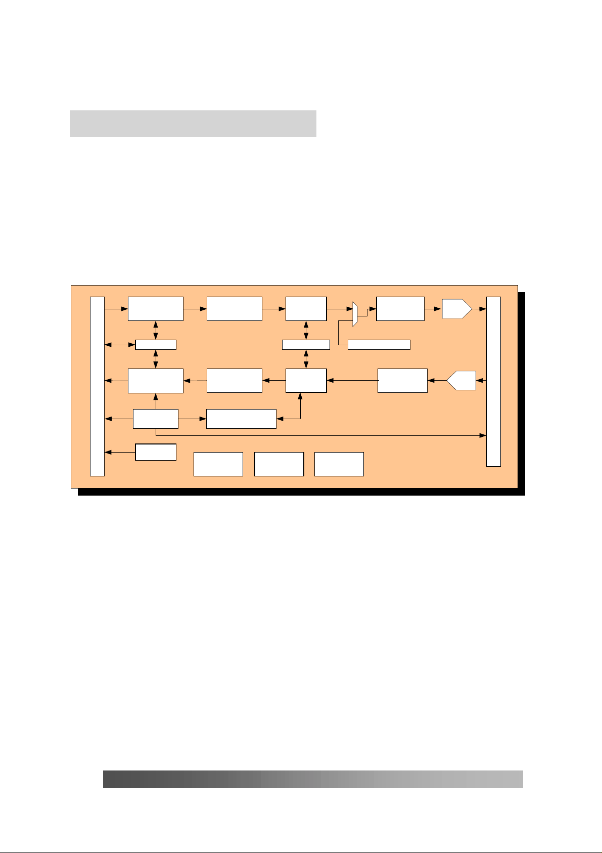
Tx MAC
Rx MAC
Modulator
Preamble/Header
Demodulator ADC
DAC
GGeenneerraall DDeessccrriippttiioonn
ADM8211 is a high performance PCI/miniPCI/Cardbus single chip with WLAN MAC cont roller and
Baseband processor integrated.
ADMtek is the leading of networking SOC, based on mature experience, ADM8211 is designed as
hardwired architecture to reach the cost eff ective target.
With the features of SRAM-needless, power saving, WEP/f ix, small-package…etc. ADM8211 is
versatile for W LAN system manuf acturers to develop IEEE 802.11b wireless product.
Tx Buffer
Management
Arbiter WEP Engine
PCI/IF Control
Rx Buffer
Management
WLAN CSR
Tx FIFO
Rx FIFO
Magic Pkt / Wake-up
Frame
Synthesizer, RF I/F
WLAN CR
EEPROM I/F LED/GPIO Clock Gen
ADMtek
Partnership Now & Future
5

2
2
FFeeaattuurreess
2.1 Host PCI interface
Provides 32-bit PCI bus master data transfer
Supports network operation with PCI system clock from 22 MHz to 33MHz
Provides performance meter, PCI bus master latency timer, for tuning the threshold to
enhance the performance
Provides burst-transmit packet interrupt and transmit/receive early interrupt to reduce host
CPU utilization.
Supports memory-read, memory-read-line, memory-read-multiple, memory-write,
memory-write-and-invalidate command while being bus master
Supports big or little endian byt e ordering
Arbitration between DMA channel to minimize underflow or overflow
2.2 Industry standard
PCI 2.2 /Cardbus interface
ACPI and PCI power management 1.1 standard compliant
IEEE802.11, IEEE802.11b
2.3 802.11 MAC
MAC implement s with State Machine
No External SRAM needed
Support auto-fallback from 11Mbps to 5. 5, 2 and 1Mbps.
Support Infrastructure, Ad-hoc under Dist ributed Coordination Function (DCF)
Implementation the Point Coordination Function (PCF) operation
RTS/CTS generation, Fragmentation, Beacon monitor/loss detection/generation.
RX DA address filtering (multicast) with 64 entries.
TIM (Traffic Indication Map) field decoding at Beacon frame reception
Support DSSS (Direct Sequence Spread Spectrum) PHY.
Front end chip power s equence contr ol
2.4 WEP
Internal encryption engine for WEP function, RC4, 40/104 bits k ey length selectable.
ADMtek
Partnership Now & Future
6
 Loading...