

Admiral (Kelon) AW-24CR3FM1 Owner’s Manual
Useand CareManual
I ®
I'%IilIL I'%1 _,1_/
= = I,I _I '11 _=I I"]11 [" = ....
bJ II111 O PIRA ... ;_,..o.=o,.o__,=
s
Remote Control
Mechanical Control
Thank you for purchasing an Admiral room air conditioner. Please read this "Use and Care Manuat" carefully
before insta/ing and using this applance, Keep this manual for future reference,
Mucl sse {;y_;as po co, uSers u_ a_e aco_ dco_ac_o_a:lmlr_ Lea _ e_t_ _e_tee IV_sn_.a _:_e_;se y
Ma_e _m en_o ;_' _esd® _tsa ;4_"y utizaf esle p_"ocluc_o Co_-_seve esle rnart_£Apaa co_-_u ts. o e_'_el utu_'o
For Service Call 1 877 465 3566
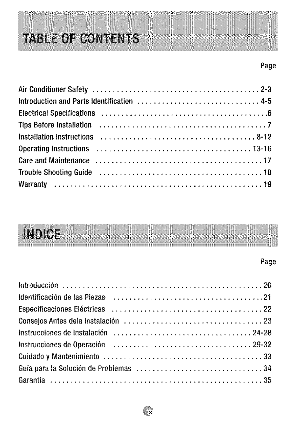
Air Conditioner Safety ............................................ 2-3
introduction and Partsidentification ................................ 4-5
Electrical Specifications ......................................... 6
Tips Before Installation ........................................ 7
installation Instructions ................................... 8-12
Operating Instructions
Careand Maintenance
TroubleShooting Guide
introd_cci6n ................
Identificaci_nde las Piezas ,,,
.... 17
.... 18
.... 19
Page
...... 20
..... 2_
Especificaciones El_ctricas ....
ConsejosAntes dela Instalaci_n
instrucciones de instaiaci_n ,,,
Instrucciones de Operaci_n ,,.
Cuidadoy Mantenimiento .....
Guiapara _aSolutiOn de Problemas.............
...... 22
..... 23
,,24-28
..29-32
...... 33
..... 34
...... 35

What YouNeed to KnowAboutSafety_instructions
Warning and _mportant Safety instructionsappearing in this manual are net meantto cover
al] possible conditions and situations that may occur. Commonsense, caution, and care
must be exercised when operating or cleaning teoJsand equipment.
Nways contact your deaJe5distributor, service agent, or manufacturer about problemsor
conditions you do not understand.
Thisis the safetyalert symbol,tt is usedto alert youto potential personalinjury hazards
Obeyall safety messagesthat fol!owthis symbolto avoid possib!einjury or death,
DANGERindicates an imminently hazardous situation which, if not
avoided, will result in death or serious injury.
WARNING indicates a potentially tlazardous situation which, if not
avoided, could result in death or serious injury.
CAUTION indicated a potentially Ilazardous situation whicl_, if not
avoided, may result in minor or moderate injury.
CAUTION used without the safety alert symbol indicated a
potentiaiiy hazardous situation which, if not avoided, may result in
property damage.
SAFETY
To reduce the risk of fire, electrical
shock, or _nju y when using your air
conditioner, follow these basic precautions:
- Plug into a grounded
3-prong outlet.
o Do not remove
ground prong.
• Do not use
an adapter.
' " r
• Do not use an extension cord.
Unplug air conditioning
before servicing.
Use two or more people to move
and install air conditioner.
INSTRUCTIONS
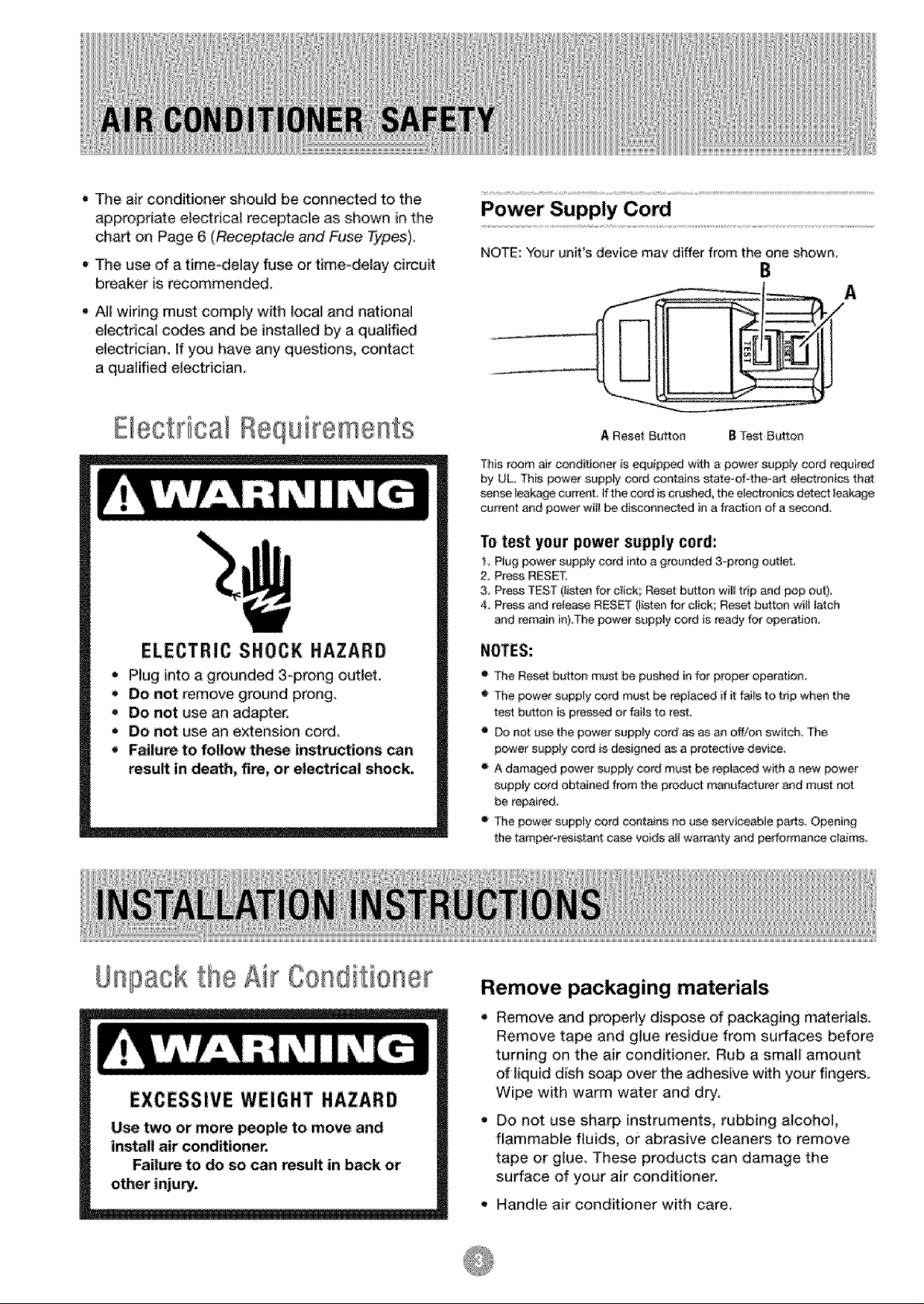
• The air conditioner should be connected to the
appropnate eJectrical receptacle as shown in the
chart on Page 6 (Receptacle and Fuse Types).
- The use of a time-delay fuse or time-delay circui_
breaker is recommended,
t A!! wiring must comply with _ocaland nationa!
electrical codes and be installed by a qualified
ele_rician, tf you have any questions, contact
a qualified electrician.
Power Supply Cord
NOTE:"Yourunit's device may differ from the one shown.
B
E ectrical Requirements
ELECTRIC SHOCK HAZARD
Plug into a grounded 3@rong outlet,
Do not remove ground prong,
Do not use an adapter.
Do riot use an extension cord
Failure to fo|low these instructions can
result in death, fire, or electrical shock.
A Reset Button B Test Buttes
This room air conditioeer is equippedwith a power supplycord required
by UL This power supply cord contains state-of_theoart eJe_Xronicetha_
sense _eakage Cu_nL #t_ cord is crush_, the e!eetronics detect _eakage
o_rrsnt and powe_ t wi}_ bie die_lneeted in a fraction of a seceded,
To test your power supply cord:
P!og power supp!y cord into a gro_nd_ 3,_prongoutlet,
2, Pr_e RESET
3, Press TEST (listen for click; Reset br_tton wiI! trip and pop out)_
4, Press and re_e_se RESET (listen for click; Reset button wi_ _etch
and remain hli,The power supply _rd is ready for operation
o The Res_ button must be pushed n for proper o_ration
o Tbe power s_pply cord m_st be _ep_aced_fit fai_sto trip when the
te_ button is p_ss_ or tails to rest.
_ not use the power _pp_y cord as as an off/co switch_ The
power supp!y cord is designed _ a protective device,
A damaged power s_ppiy cord must be repiaced with a new power
s_pp!y cord obtained from the produ_ manufacturer and must not
be repair_Jo
The power supply cord contains no u_ servieeabJe parts. Opening
the tamp_resistant case voids a_iwarranty and performance claim&
Unpack the Air Conditioner
EXCESSIVE WEIGHT HAZARD
Use _o or more p_p]e to move and
install air conditioner.
Failure to do so can resu_ in back or
other injury.
Remove packaging materials
Remove and propedy dispose of packaging materials,
Remove tape and glue residue from surfaces before
turning on the air condit!oner, Rub a small amount
of iiquid dish soap over the adhesive with your fingers,
Wipe with warm water and dry_
Do not use sharp instruments, rubbing alcohol,
flammabie fluids, or abrasive cleaners to remove
tape or gJue, These products can damage the
sudace of your air conditioner.
• Handle air conditioner with care.
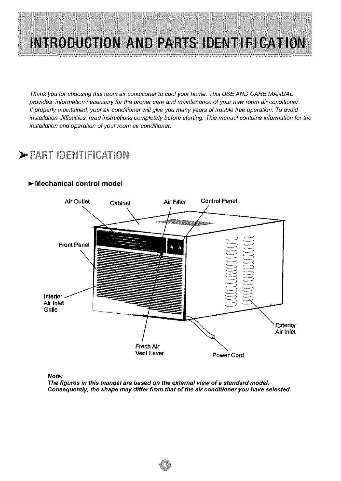
Thank you for choosing this room air conditioner to cod your home This USE AND CARE MANUAL
p_vides information necessa_ for the proper care and maintenance of your new room air conditioner.
If property maintained, your air conditioner will give you many years of trouble free operation. To avoid
installation diffTculties_ read instructions completely before starting. This manual contains information for the
installation and operation of your room air conditioner.
PAtT IIENTIFICRTIOI
I_ Mechanical control model
Air ¢-Jtet Cabinet Air Filter Co_ml Panel
I_edor
Air Inlet
Grille
/
Fresh Air
Vent Le_r
Note:
The figures in this manual are based on the external view of a standard model
Consequently, the shape may differ from that of the air conditioner you have selected.
Power Cord
Air Inlet
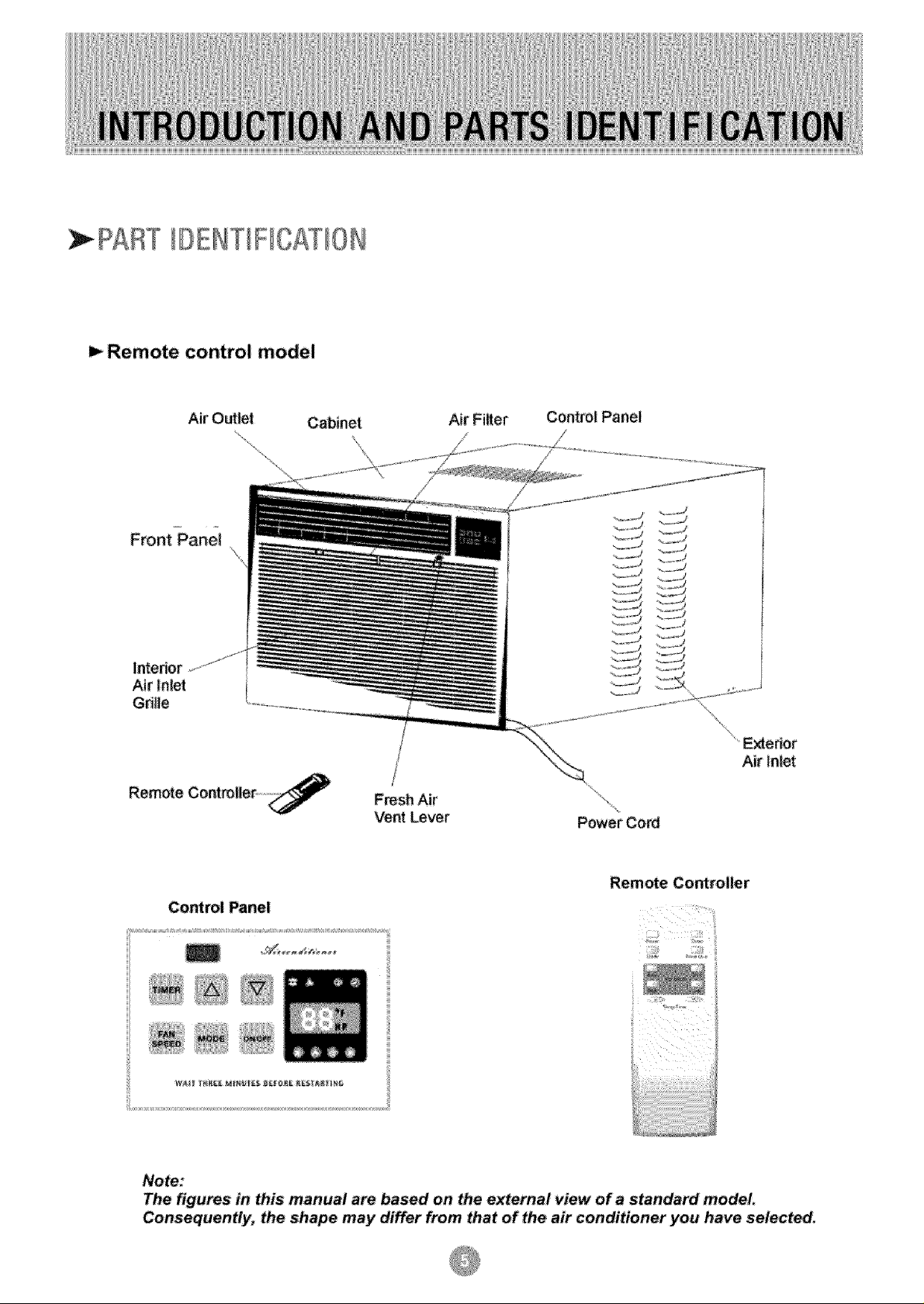
PART DENT F CATION
Remote control model
lntedor
Air Inlet
Gdlle
Air Outlet Cabinet
Fresh Air
Vent Lever
Air Fi_er Control Panel
E_ertor
Air In_et
Power Cod
Remote Controller
Control Panel;
Note:
The figures in this manual are based on the external view of a standard model,
Consequently; the shape may differ from that of the air conditioner you have selected,
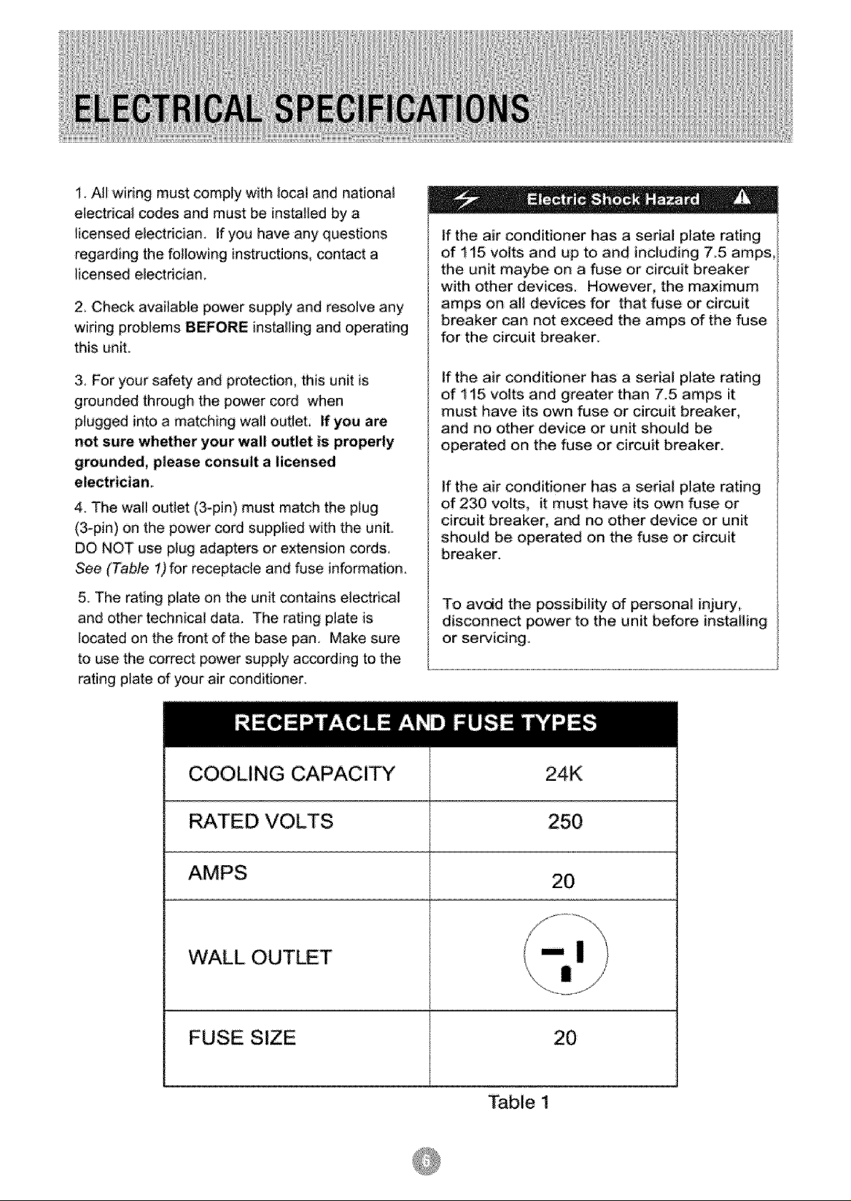
1, A!l widng must comply with local and national
electrical codes and must be installed by a
licensed electrician If you have any questions
regarding the following instructions, contact a
iicensed electrician.
2, Check available power supply and resolve any
wiring problems BEFORE installing and operating
this uniL
If the air conditioner has a serial plate rating
of t t5 volts and up to and including 7.5 amps,
the unit maybe on a fuse or circuit breaker
with other devices. However, the maximum
amps on a!! devices for that fuse or circuit
breaker can not exceed the amps of the fuse
for the circuit breaker.
3, For your safety and protection, this unit is
grounded through the power cord when
plugged into a matching wall outleL If you are
not sure whether your wall outlet is properly
grounded, please consult a licensed
electrician
4. The wail outlet (3_pin) must match the piug
(3-pin) on the power cord supplied with the unit.
DO NOT use plug adapters or extension cords,
See (Table 1) for receptacle and fuse information,
5. The rating plate on the unit contains electrical
and other technical data, The rating plate is
located on the front of the base pan. Make sure
to use the correct power supply according to the
rating plate d your air conditioner.
COOLING CAPACITY 24K
If the air conditioner has a serial plate rating
of t 15 volts and greater than 7_5 amps it
must have its own fuse or circuit breaker,
and no other device or unit should be
operated on the fuse or circuit breaker.
If the air conditioner has a serial plate rating
of 230 volts, it must have its own fuse or
circuit breaker, and no other device or unit
should be operated on the fuse or circuit
breaker_
To avdd the possibility of personal injury,
disconnect power to the unit before installing
or servicing.
RATED VOLTS 250
AMPS 20
WALL OUT T
FUSE S!ZE 20
Table I
Your Room Air Conditioner unit is designed to
be highly efficient and save energy. Follow these
recommendations for greater efficiency.
1 Select thermostat setting that suts yeur
comfo_ needs and leave the thermostat at
that chosen se_ing,
"four RoomAir Conditioner was designed
for easy installation in a single or double-hung
window. NOTE*. This unit is NOT designed for
,vertical (s_ider type) windows
2._The air filter is very_efficient in removing airborne
particles. Keep the air filter clean Typicalfy, the filter
should be cleaned once a month. More
frequent cleaning may be necessary depending
on outdoor and indoor air qua_ity_
3. Use drapes curtains, or shades to keep direct
sunlight from heating your room, but DO NOT
obstruct the air conditioner. Aiiow three (3) inches
around unit to circufate.
4_Start },our air conditioner before outdoor
air becomes hotico_d and uncomfo_abie This
avoids an initial period of discomfort while
the unit is cooling or heating off the room
5 When outdoor temperature is cool
enough, use HIGH or LOW FAN
only.. This circulates indoor air; providing
some coo_ing comfort and utilizes less
electricity than when operating on a
To avoid insta|iation/operating difficul_ise,
read the ;instructions thoroughly,
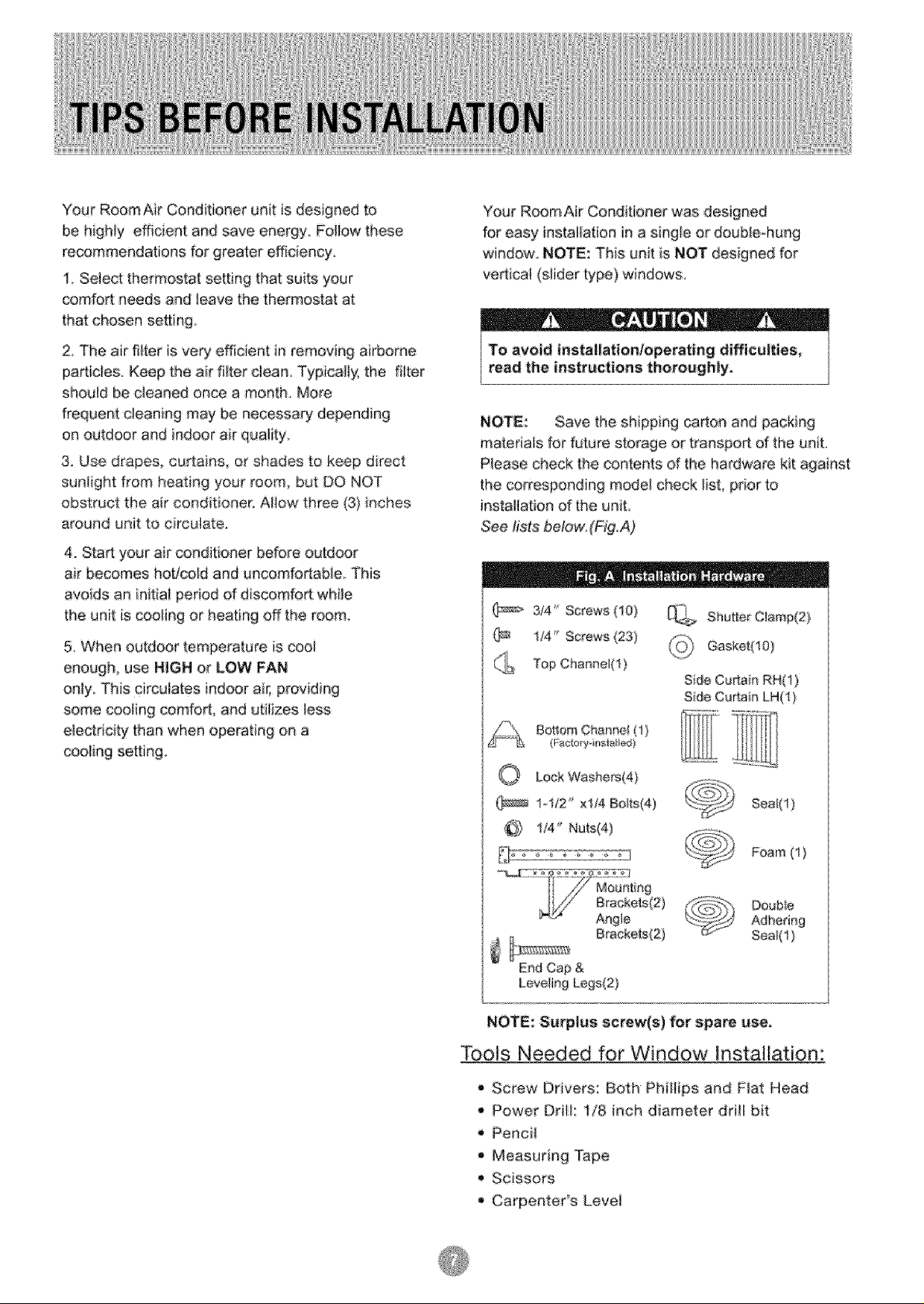
NOTE: Save the shipping carton and packing
materials for future storage or transpo_ of the unit
P_ease check the contents d the hardware kit against
the corresponding model check list, pdor to
installation of the unit
See tis_ below.(Fig.A)
(_> 3/4 _ Screws 410}
i/4 _ Screws (23)
Top Channel(1 )
BoHomChar_nel(i)
(Fac_:_'y-it_stalied
_ Shut[er C_amp(2)
_ Gasket(10)
Side CuAair_ RH(1)
Side CuAain LH(I )
O LockWashers(4}
(_ 1_!/2 xt/4 Boffs(4)
@ !i4" Nuts(4)
Do#b_e
End Cap &
Leveling Legs(2)
NOTE: Surplus screw(s) for spare use,
Tools Needed for Window Installation:
Screw Drivers: Both Philiips and Flat Head
,_ Power Drill: 1/8 inch diameter drill bit
Pencil
• Measuring Tape
'_ Scissors
• Carpenter's Levei
Becausethecompressoristocatedonthe
controlssideoftheunit(rightside},this.side
willbeheavierandmoreawkwardtomanipulate.
Inadequatesupportoncontro_sideof theunit
canresultinpersonalinjuryanddamagetoyour
unitandproperty.Therefore,itisrecommended
tohavesomeoneassistyouduringtheJnstailation
d this unit.
1, Select the Best Location
A, Your room air conditioner was designed to
fit easily into a eingte or double hung window However
since window designs vary, it may be necessary to
make some modifications for safe and proper
installation.
B. Make sure window and frame is structuraiiy
sound and free from dry and rotted wood
E. Be eerta n the proper electnca! outlet is within reach
d the insta!lation, Use only a single outlet circuit rated
at proper current: (see table 1 on page 6 ), All wiring
should be in accordance with local and national
eiectdcal codes_
R Your unit was designed to evaporate oondeasatbn
under normal conditions. However under extreme
humidity conditions, excess condensation may cause
the basepan to overflow to the outside.
The unit should be instalied where condensation
rumoff cannot ddp on pedestrians or neighboring
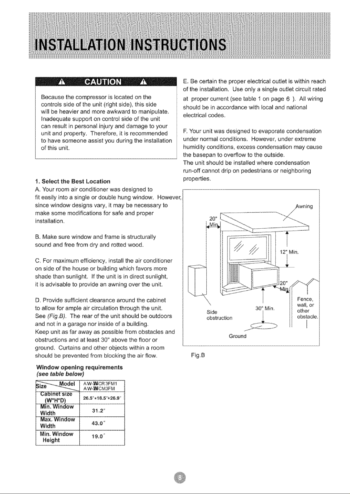
C. For maximum efficiency, install the air conditioner
on side of the house or building which favors more
shade than sunlighL If the unit is in direct sunlighL
it is advisable to provide an awning over the unit,
D Provide su_cient clearance around the cabinet
to allow for ample air circulation through the uniL
See (Fig.B). The rear of the unit should be outdoors
and not in a garage nor inside d a building.
Keep unit as far away as possible from obstacles and
obstructions and at !east 30" above the floor or
ground Curtains and other objects within a room
should be prevented from blocking the air flow.
Window opening requirements
'see table be!o_
(W'*H,U)
Mira WindOW
Width
Width
Min. Window
Height
31,2 _'
43,0 _
19_0'
Side
obstruction
Fence_
Wa_, or
other
obstacle.
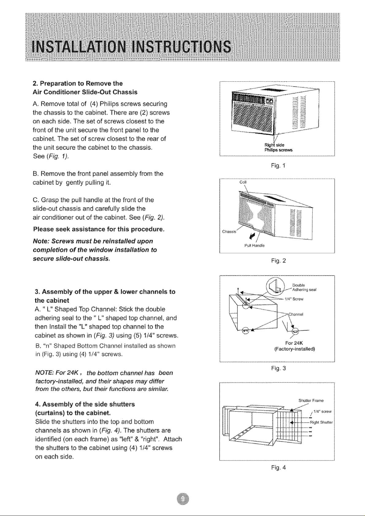
2, Preparation to Remove the
Air Conditioner SHde_Out Chassis
A, Remove totai of (4) PhHips sc:rews securing
the chassis to the cabinet. There are (2) screws
on each side The set d screws closest to the
front of the unit secure the front pane! to the
cabinet The set of screw closest to the rear of
the unit secure the cabinet to the chassis.
See (Fig, 1).
& Remove the front panel assembly from the
cabinet by gentty pulling it,
C, Grasp the pull hande at the front of the
siide-out chassis and carefuliy slide the
air conditioner out of the cabinet. See (Fig_ 2),
Please seek assistance for this procedure.
Note: Screws must be reinstalled upon
completion of the window installation to
secure slide-out chassis
Fig, t
3. Assembly of the upper & lower channels to
the cabinet
A " L° Shaped TOp Channd: Stick the double
adhedng seal to the" L" shaped top channel, and
then Install the "L" shaped top channet to the
cabinet as shown in (Fig. 3) using (5) 1/4" screws.
& "n" Shaped Bottom Channel installed as shown
in (Fig, 3) using (4) 1/4" screws.
NOTE: For 24K , the bottom channel has been
factor/,instafled, and their shapes may differ
from the other, but their functions are simila_
4, Assembly of the side shutte_
(curtains) to the cabinet,
Siide the shutters into the top and bottom
channels as shown in (Fig, 4). The shutters are
identified (on each frame) as "left" & "right"_ Attach
the shu_ers to the cabinet using (4) 1/4" screws
on each side,
For 24K
{Fador_'4nstalied}
Fig 3
Fig, 4
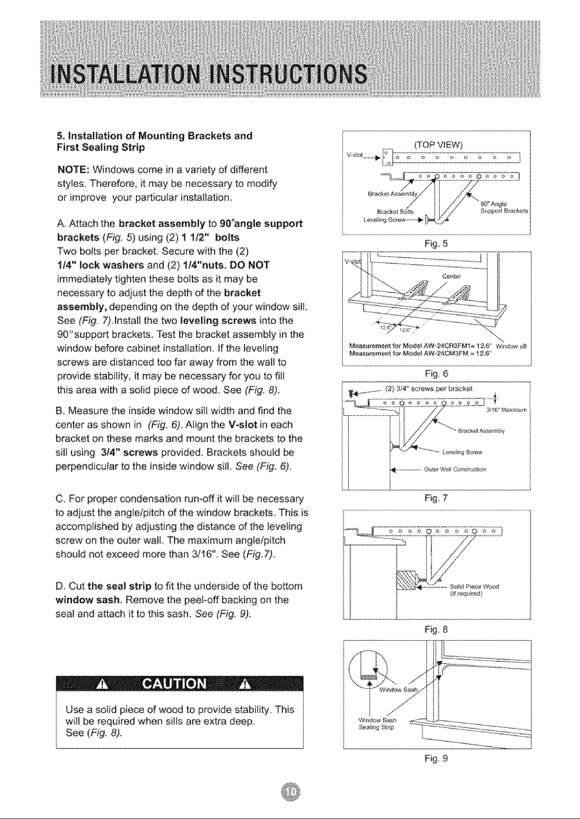
& Installation of Mounting Brackets and
First Sealing Strip
:NOTE: Windows come in a variety of different
style& Therefore it may be necessary to modify
or improve your pa_icu]ar installation
A Attach the bracket assembly to gO°angle suppo_
brackets (Fig, 5) using (2) t t/2" bolts
Two bo_ts per bracket, Secure with the (2)
1/4" lock washers and (2) 1/4"nuts. DO NOT
immediately tighten, these boIts as it may be
necessary to adjust the depth of the bracket
assembty, depending on the depth of your window siII.
See (Fig, 7),Install the two leveling screws into the
90" suppoA brackets. Test the bracket assembly in the
w[ndew before cabinet insta{_ation, if the _eveling
screws are distanced too far away 'from the wali to
provide stabi{ity it may be necessa_ for you to fil_
this area with a solid piece of wood See (Fig: 8)
B, Measure the inside window sill width and find the
center as shown in (Fig, 6), Align the V-slot in each
bracket on these marks and mount the brackets to the
sill using 3/4" screws provided Brackets shouid be
perpendicular to the inside window sill, See (Fig: 6),
Fig, 5
Meas_mer_ f_{ Mc,de_ AWo24CR_FMi_ i 2,#" W nt_r_ sH
Mea_ment _or Mode_ AW-24CM3FM = 12,6
Fig, 6
_,_ .............. (2) 3_ _'screws pet b_acge_
C For proper condensation run-off it wili be necessa_
to adjust the ang!dpiteh d the window brackets, This is
accomplished by adjusting the distance d the leveting
screw on the outer wall, The maximum angfetpitch
should not exceed more than 3/16'L See (Fi'g.7),
D Cut the seal strip to fit the underside of the bo_:om
window sash Remove the peekoff backing on the
seal and attach it to this sash. See (Fi9, 9).
Use a solid piece of wood to provide stability This
will be required when sills are extra deep,
See (Fig 8)_
Fig, 7
Fig, 8
Fig, 9
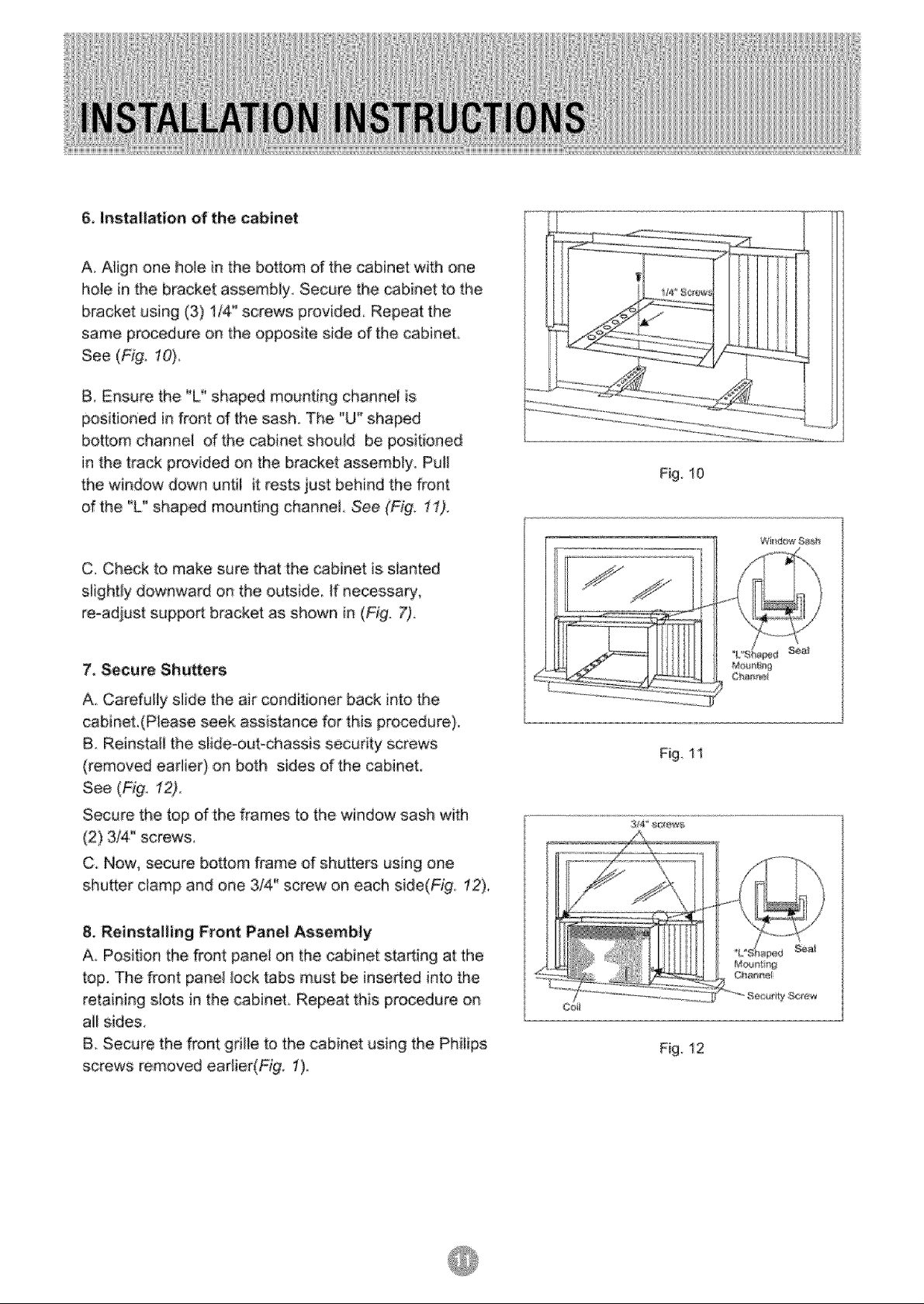
& Installation of the cabinet
A Align one hole in the bottom of the cabinet with one
hole in the bracket assembly Secure the _binet to the
bracket using (3) 1/4" screws provided Repeat the
same procedure on the opposite side of the cabinet,
See (Fig. 10)
B Ensure the "L " shaped mounting channel is
positioned in front d the sash. The "U" shaped
bottom channe_ d the cabinet should be positioned
in the track provided on the bracket assembly Pu!!
the window down unfii it rests just behind the front
d the "L" shaped mounting channel See (Fig 11).
C, Check to make sure that the cabinet is slanted
slightiy downward on the outside tf necessary,
re-adjust suppo_ bracket as shown in (Fig. 7).
Fig 10
'Wi_daw _h
7_ Secure Shutters
A° Carefully slide the air conditioner back into the
cabineL(Please seek assistance for this procedure).
B. Reinstall the slide_oubchassis security screws
(removed eadier) on both sides d the cabinet
See (_g. 12).
Secure the top of the frames to the window sash with
(2) 3/4" screws
C_ Now, secure bottom frame d shutters using one
shutter ctamp and one 3!4" screw on each side(Fig: 12).
8. Reinstalling Front Panel Assembly
A, Position the front pane_ on the cabinet .starting at the
top, The front panel lock tabs must be inseAed into the
retaining s_ots in the cabinet. Repeat this procedure on
all sides.
B. Secure the front grille to the cabinet using the Phiiips
screws removed earlier(Fig. 1).
Fig.I 1
Ce_
Fig.12
 Loading...