

Admiral (Kelon) AW-18CR3FM, AW-12CR1FM1 Owner’s Manual
Useand CareManual
AIREACOND_OfON£[}OPASAS/_BITAC_O_ES
Manualde Usey Mantenimien_e
Remote Contro!
AW-12CRi FMi
Mechanical Control
Thank you for purch_ng _ _ room aJt conditton_, Ple_e _ad this "U_ _nd Ca_ Manual" y
before installing _d using this _p!_ano& Keep this manua_ for f_ure r_erence,
Muchase gracias po_ comprar un aire acond_cio_ado _al Laa ate_tamente e_"Manu,a_de Uso y
Man_enimier_to _ ar_es de i_sta_ar y uti_zar _ste proda_to, Cow.rye ÷_te maa_a_ papa consu_tado e_ ÷_f#turo
ForService Cal! ! 877 465 3566
Papa@tsnsr servici0 teen c0, Hamsa_ 1 877 485 3586
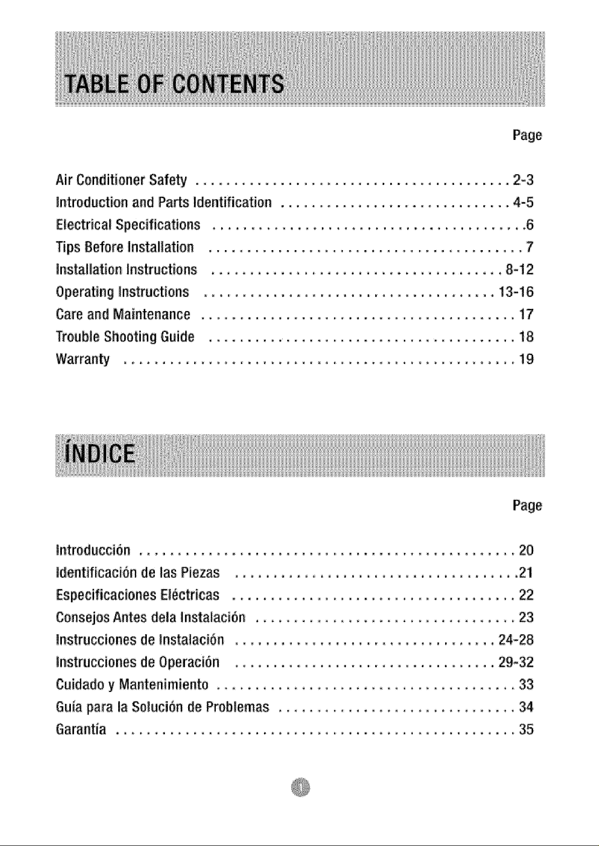
Page,
AirConditionerSafety
_ntroduction and Pa_s ildentification
Electrical Specifications
Tips Before Installation
installation Instructions
Operating _nstructiens
Care and Maintenance
Trouble Shooting Guide
Warranty .....................
,°. 2-3
.., 4-5
.... 8-12
,13-16
...... 17
...... i8
....... i9
tntrod_cci6n ........................
Id.entificaci6n de las Piezas ...........
Especificaciones E!_ctricas ...........
Consejos Antes_ela Instalacion ........
Instrucciones de !nsta!a¢i_n ............
Instrucciones de Operaci_n ...........
Cuidado y Mantenimiento .................
Guia para la SolutiOn _e Prob!emas ..........
Page
..... 20
..... 21
..... 22
...... 23
,, 24-28
.. 29-32
...... 33
...... 34
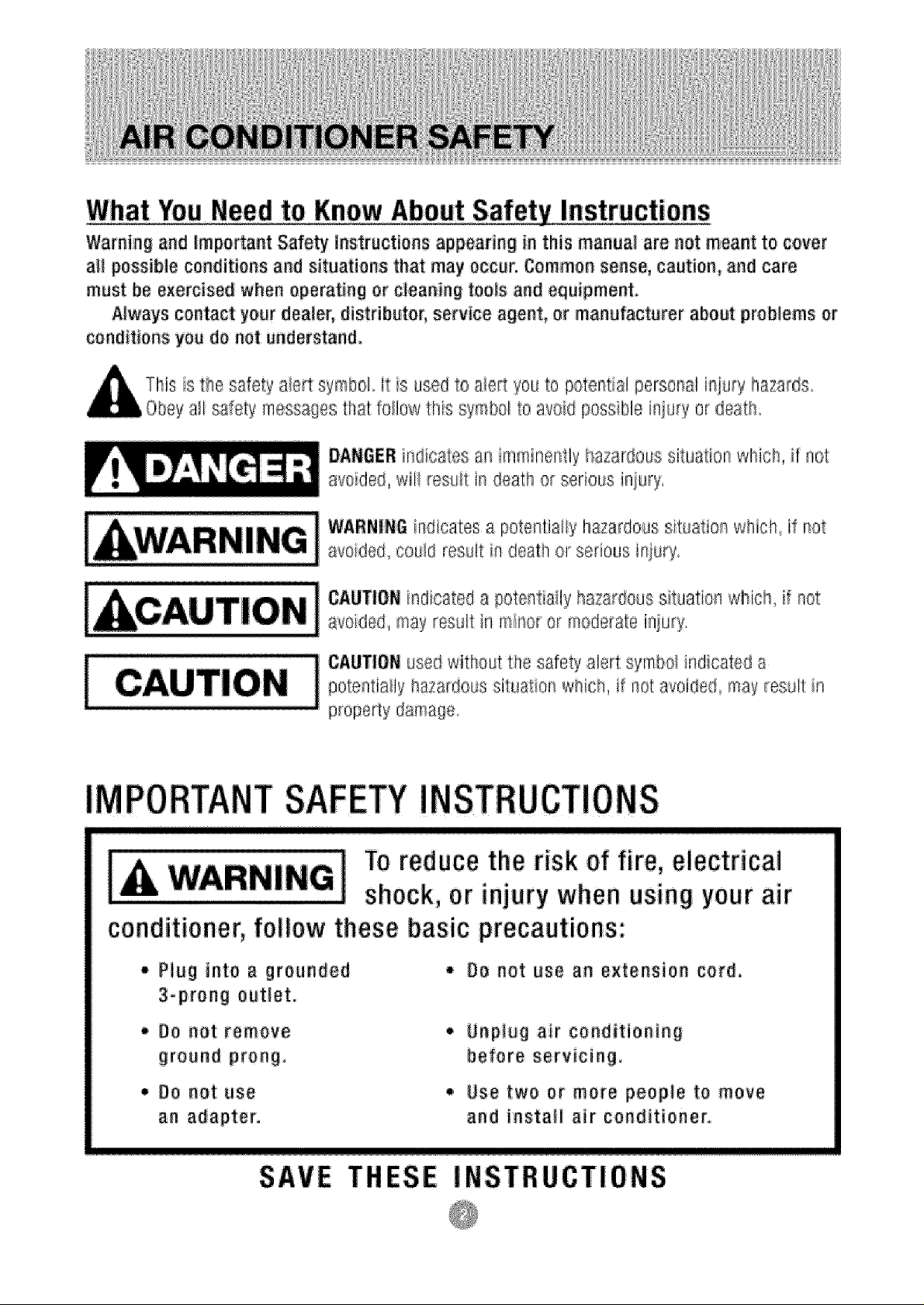
What YouNeedto KnowAbout Safety !nstrucions
Warning and |tape,ant Safety instructionsappearing in this manua! a_enot meant to cover
aiI possible conditions and situations that may occur. Common sense, caution, and care
must be e×ercised when operating or cleaning tools and equipment.
A_ways contact yourdenies distributor, service agent, or manufacturer about problems or
conditions you do not understand.
This isthe safety alert symbol tt s usedto a./ettyou to potential personal injury hazards.
a_l safety messagesthat feiiow this symbol to avoid poss_blsiaiu_yor death
t"
DANBEB n .........
avoided, wil! resu!t in death o_serious in ury,
WARNINGindicates a potent:ia!iyhazardoussituation which if not
avoided could result in deatil or serious injury
CAUTIONindicated a potentia_iyha,__.ardouss tuat:ionwhich, if not
avoided, may rose,It in rnlne_'or moddate !aiu_y.
i CAUTIONu_._ _,ithout the safety alert symbol indicated a
: ........................ property damage.
educatesa, imminently hazardoL_ssituatior} _@ich,ir nO|
v,'h_ch,if net avoided may LresultInpotentia!ly hazardoussituation ,
PORTANT I STRUCTIONS
To reduce the risk of fire, electricai
shock, or injury when using your air
conditioner, follow these basic precautions:
• Pl_g into a greunded
3*prong out!at.
= Be net remove
ground prong.
,, Be net use an extension c,ard.
• Unpiug air conditioning
before servicing,
, Use two or more people to move
and instate air conditioner.
THESE INSTRUCTIONS
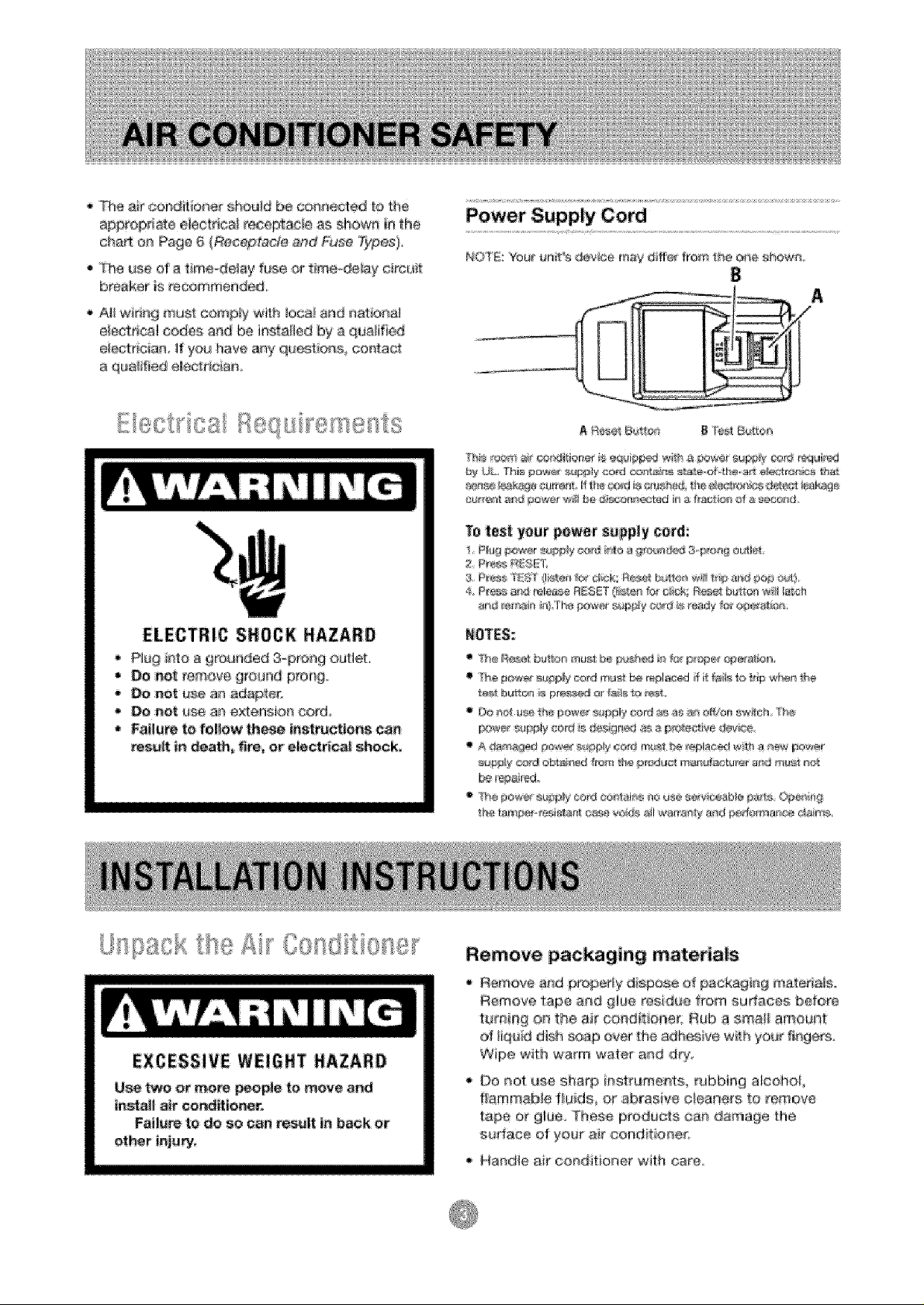
The air c{:_r_dit;io{}ershould be con_led tOthe
appropd_e electdea receptacle es _how_ _ the
cha_ on Page 6 {Receptacle and Fuse Types}
• The use d a time_de_sy fiJse or tireeode_ay c#cu_
brea_,er ff__scommef_d_,
Alt wideg must c_'_p_y with loea_and _atio_al
e_ectr_calcedes and be in.ailed by a que_ifie_
e_ectnci_ if you have any qa_tioas contact
a qualified elee_raeiaz_,
ELECTRIC S_OCK NAZA_O
P_u_r_to _ 9rounded 3-_)r_g outlet,
• Do _t reme,_egro_Jndprong,
Do _t use a_ adapter.
Do _ot use ar_extensior_ cord,
• Failure to foflow these instru_!en_ ea_
_sult in death, fire, or e_ctric.sl shock,
Power ;Supply Cord
_ UL Thie p_ r_sf@ly cc_d _#_s s_a_-_Fthe at1 e[es_f_r_s t;ha_
Te test your power s_pp_y cerd:
4 P_e_ &_ rele_e R_GET O_slet_for c;{mk Re_el:bu_tc¢_w_Jtat_sh
EXCESSIVE WEI6BT HAZARO
Use two or more _o_e to move and
install air oer_ffioner.
Fol!ate to _o so can result !_ back ot
et_r inju_,
Remove packaging materials
Remove arid pr_erly dispose of packag_n_ materials
Remove tape and glue residue from surteces before
turnillg on the ai_'coed_tio!_e{. Rub a smai_ amount
o_ }iq_td dish _yaap over the adbe@ve w_h you_ fl_3ge_
Wipe with warm water and @y
Do not use sharp i_st_uments rabMng alcohol
flammable fiu_ds or abras4ee c!eaners to _emeve
tape ot gl_e_ These products oa_ da¢[_age the
sumacs of your air co_di_ior_e_,
•, Handle a_r conditione_ w_th care°
Thank you for choosi_g this room air cond_ioner te c_l your heme This USE' AND CARE MANUAL
provides info\_mation neee.sea_, fer _he proper care and mainfenenee d your r_ew r_m ai_r_n
ff propedy ma_atained_ yoer air cond:'t_e,'_er wilt g_ve you malty year.s d trouble free operatie_ To avoid
_stellat_on' ,read imstructiens ca _[ore starting, ThLs manuai contains _nfermat_on for the
t_etatJaben and operation of yeu__r_x_m air c_ondidoner.
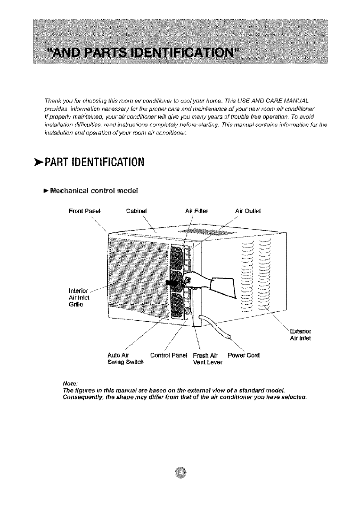
: PARTIDENTIFICATION
Mechanical control model
A_r |nlet
Auto Ajar Cow,rot Panel Fresh
Nete:
The figures in this man_a! a_, bas_ on the extema_ view of a standard model,
Consequentty, the shape may differ from tha_ of the air conditioner yo_ have selected,
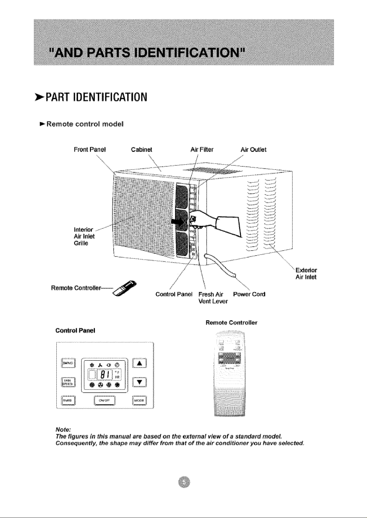
PART IDENTIFICATION
Remote control mode|
Retake Controller
Control Pa_l
Note:
The figures in this manual am based on the external view of a standa_ model,
Consequentfyi the Shiape may dt_t from that of the air conditioner you have selected
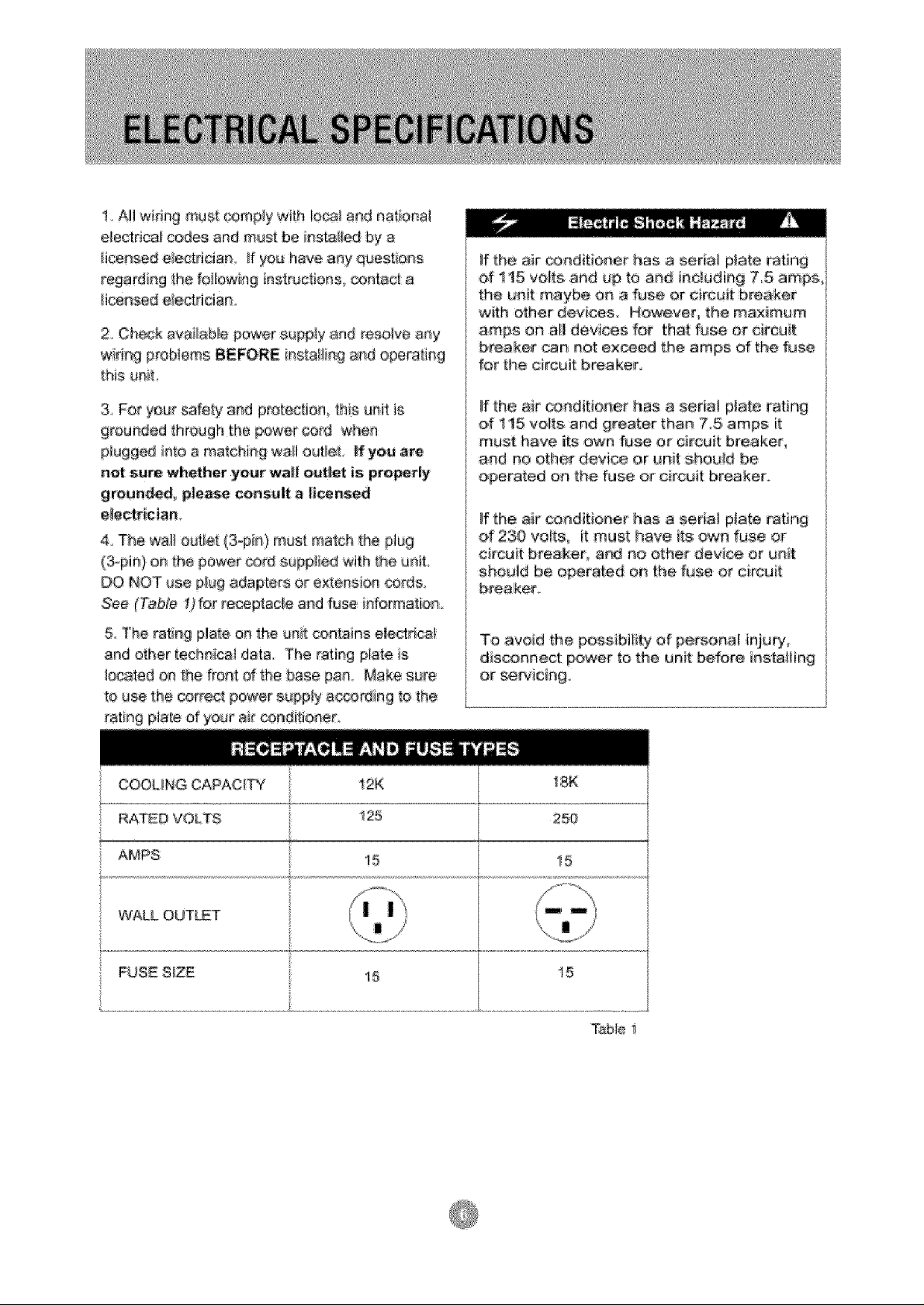
1 Al_wide9 must _3mp_y with !o_ and nationa_
electrical cedee and must be insta le_ by a
_icensed e_ectdcian. _f yo_ have any q_eatio_s
regardi_g the fo!_o_#lg ir_structions, _ata_ a
Hceesed e_ectdoia;n
2, Check avai!ab!e power _uppty and resolve ar_y
BEFORE installing and opera_in;g
this unit,
If the air ,conditioner has a serta_ plate rating
of tt5 volts and up t_ and i_elud_n# 75 amps,
the _,_nitmaybe on a fuse or circuit breaker
with o!:her devices, However the maximum
amps On a|! devices for that fuse or drcuit
breaker can _ot exceed the arnps of the fuse
for [he circuit breaker.
& For ye_r safety and protection, this unit is
grounded through the power cord when
p_ugged into a ma_chi_9 wail outlet If yea ,are
net sure whether yoer waft outlet is properly
grounded, p|ease co_sult a |fcensee
electrician_
4_ The walt outiet (3-pin) mast match the plug
(3_pie) on the power _rd supp!ied with _he unit
DO NOT _se p_ugadapters or extensior_ cords,
See (Table t) for receptacle and fuse informa[bn
5 The rating pl_e oa the unit cen_Jns etect_caf
arid other technic| data, The rating ptate is
_ocated on the front of _h,ebase pan Make sure
to use the correct power suppiy a_cordiag to the
rating pla_e of your' air conditioner
COOUNG CAPACITY 12K
RATED VOLTS _ 1:25
AMPS
!5
!f the air cOnditiOner' has a serial p_ate rating
ef 115 volts and greater than 75 amps it
must have its own fu_ or circuit breaker,
and eo other device or ,unit she_!d be
operated oa the fuse or circuit breaker..
!f the air conditioner has a sofia! ptete rating
d 230 vo_ts_ it must have its r_c_nfuse or
circuit breaker_ and no other de'vice or _t
should be opera|ed or_ the f_sse or circuit
breaker
To, avoid the pOS:gi_bt!i_y Of persoaal ieju_,
disconnect power to the unit before i_stal_ing
teK
250
15
WALL OUT_T i::
FU$_ S|Z_ t5 15
Table i
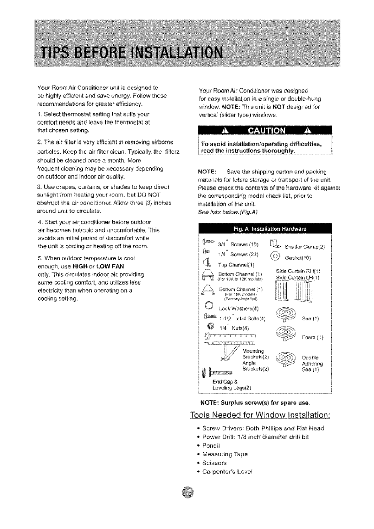
Y¢_arR®m Air Conditioner unit is designed to
b_ hi#Hy efficien_ and save energy Foi_owthese
re_mmendatio_e for grea_er efficiency.
1 Se!ec__hermosta__[_isg _ha_sui/tayc4.Jr
eomfo_ needs an_ _eavethe _,het-moa_ala_
tha_chose_ _tin 9
2:,The air filter is ve_lefficTenI# remeviag aid_ome
panicles, Keep _heair filter clean, Typically, _he _lterz
sh_J!d be c_eaned once a raonth,,More
ffequeet c!eaniw,j may be necessary depending
on euldoor al_d ndoor ar qua!_ty:
3. Use @apes curtaiss, or shades to keep direct
s#rdight _rom heatihg your reom_ but DO N©T
obstruct the air condit oner, Allow _hree (3} inches
around unit [o c rculate
4_StaA your ar co_d]ti4x_erbefore ouAoor
ar becomes ho_'cold and #ncomfoAabie° This
avoi,ds an init_a_perkedo_d scomfoA whWe
the _nlts cool ego heat r_goff _he room.
5, When so}door tem_ra{ure is cool
enough use HIGN o_ LOW FAN
O_y:. This eir¢#late_ i_d_ot ai_ #tovid #g
some ¢ool _g ce_far_ and uti_ize_ !es_
electricity i_a_ when operating o_ a
c_ ng se4_in_
Your RoomAr Cend _ioaerwas d_igmed
for easy #sia_la_ionn a single or doub_eohung
wiadew, NOT_: This unit is NOT des_gne_for
verti@l (slider ty_)wi_ows
NOT_: Save _e sh_pping ear,on a_d gacking
matedats fo_"_ature stor_4e or t_anspo_ of [he ueiL
Piease check thecontentsof_he h_rdware kit_ai_st
me cerresr_ndiag rnc_delcheck _ist, prior Io
es[a !atiea of _he u_it.
See fists be_owo(Ftg_A)
@_ 3/4_ Screens!_0)
Top C_a_ei(1 }
FI)_ !8e i'_@}@
O Lt×;kWashes(4)
_ 1o12 x174B_ts(4)
_!_ Sh:utte_C]_mp{2}
(C:o
Foam(1}
NOTE::Sa_l#s screw(s) fo_ spare u_o
$oois Needed forWindow installatiom
Screw Drivers: Both Ph_Hips and Fiat Head
Power Od!|: 1/8 _nch diameter dril_ bit
Penc_f
* Measurin 9 Tape
, Scissors
Carpenter s Level
M
Because the _m_ressor is _ted on me
_e[ro_s side of the _nit _Ln_-_htside} [n_s s_ee
w_ _ heawer a_d more awkward _o man, pu_e_@,
hadequate suu_rt on con[tel s#de of the unit
_n resu_[ _ personal hjury ar_e aamaqe to you_
anit and oreDedy Therefore tl is r#commende[J
to have sc me£'_e asses[ you _Junrl_ tr_e installation
of th_s ur_!
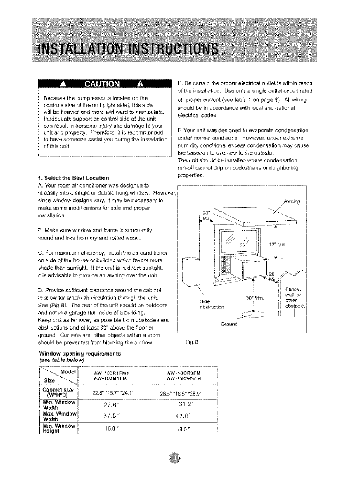
!_ Select the Best Lo_tiion
A Ybur r®m air cenditior_er was designed to
#[ easily ate a single or douNe hung window Howeve_
snce window designs 'vary, i_may be eecessaPj to
make s_amemod_@t;oas for safe a_ prope_
iastal_at[ion
B. Make sure window a_ frame is s_ruet_ra_y
sound arid free from d_ _d rotted wa(_
C. For maximum efficiency_ i_stait the ar oa_ tioner
on side of the house o_ buid_ 9 whch _aeo_s r_e_e
shade Lhae s_ntighL ]f the unt _sr_ direct sus_ight ,
it S adviaabie to _vide an awaing over the _it.
Be certain [he proper eiectrica! out_et is wiLh_a reach
d _he ir_staiiation Use a_ly a single outlet circ_it rated
at p_r c_rree_; (_..e tab@ 1 on page 6} AI! w_ring
should _ ia a_erdaa.ce wi[h local and national
e!ectricat oedes,
R You_ unit 'was desigaed _oevaporate condensation
#ader r_ermal _nd_ens However, u_der ex£reme
humidly c,o_ditior_s, excess condensati@_ may cause
the base_an to evedtow to [he euB_ide.
The unit should be i_s[a_led where con,de_satiar_
_un_offcannot ddp oe _des_da_'_s ot _eighbo_ _
O Provide S!_ffieiente£earance around the cabinet
to a]!ow for ample ar circulation through _heuniL
See _'Fig,B} The rear d [he ua}t s_td be outdoors
and net n a 9arage nor inside d a haydn 9
Keep u_t as far away as _oss b_efrom obstacles and
obs_uc_[o_s asd a_leas[ 30_above the 8oar e¢
#ro_d. C_aiee and other objects withia a room
should be prevented #era b!eek_ 9 the air flow,
W'i_dow o_ing requirements
AW-t2C_! FM
228 !:5 24.
26.5'iB5_*26.£'
AW - ! 8 CR3F_'_
AW_!@OM3FM
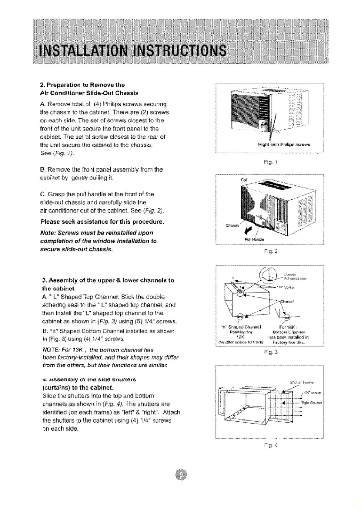
2, Preparation to Remove the
Air Conditioner S_ide,,Out Chassis
A Remove to¢a_d (4) Phiti_osscrews securin 9
the chassis to the _binet There are (2} serews
o,r_each side The set of screws cioses_ fo the
front of the unit secure the f_o#t pane_ to the
caWnet, The set of _ew cioses_ _othe rear of
the unit _e the _bi_et to the chassis,.
See (Fig, t)
B, Remove _he front panel sss÷mbfy from the
cabinet by geai_y palling i1:,
C, Grasp the pu_Ihandle a_the front of the
s!ide-out ehass s and carefully s!ide _he
air _nditi_ner out d _he cabinet, See (Fig: 2),
Please seek aests_nce for this procedure°
Note: Screws must be reinstalled #pen
completion of the window installa#on te
secure slide-out chas_s;
3, Assembly of the upper & lower chennels te
the cabinet
A _ U' Shard Top Cha_nei: Stick the double
adhedng sea _othe ° L" shaped top cha_ae_ and
then _nstalmthe "U' shaped top chan_el to the
cab Re{ as shown in (Fig, 3_ using (5} 1/4" screws,
B r'_" Shaped Bottom Charnel _sta_led as shown
h (Fg 3) using _[4}I/4' se_ev#s,
NOTE: Foe fSK _ the #otto_ cttahne# has
been f_tery.#'_stalt_, and their shapes may differ
£_0_ the others_ but their functiens a_ sim_lar.
(_u_ains) to the cab_net_
Siide the sh_ers into the top and bo_om
charnels as shown in (Fig. 4), The shuttets are
idenffied (on each fra_e) as "left'"& "r_ght!L AAach
the shut,era to the cabime_using (4} lf4" screws
or_each s_de,
_K ba_,b_ _t_t_alted}#
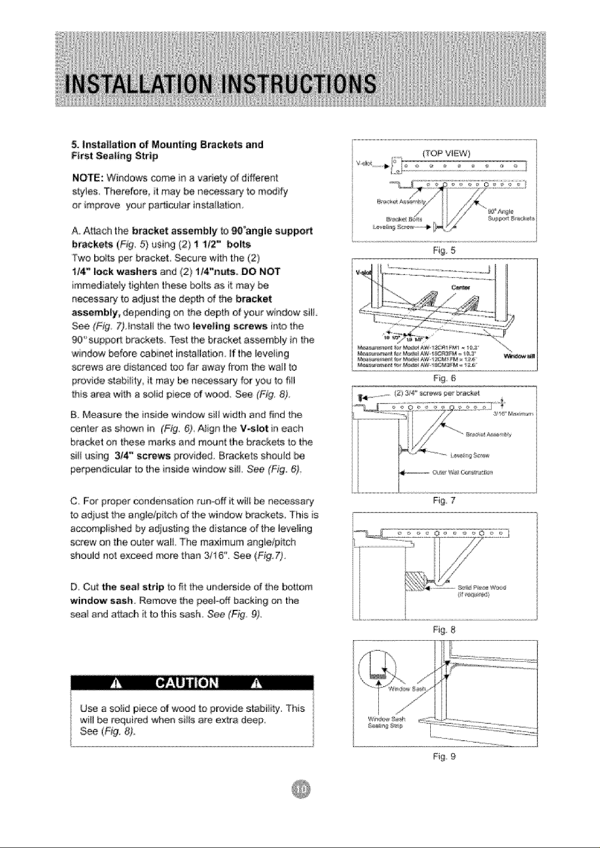
& _nsta_ation of Mounting Brackets and
First Seaiing Strip
{TOPVIEW)
NOTE: Windows come i# a variety of different
st=y:tes,Therefere_ it may t_ ne_ssa_ _o modify
or mp_ve your pa_iouJar i_statla_:ioa
A, At_.achthe bracket assembly _a_°angle :support
bracke_ (Ffg 5) _si_g (2} ! !/2"' bolts
Two bo_tsperbracket Secul_ewith the (2)
1/4," I_k washers a_d (2) 1/4"nuts. DO NOT
immediately tighte_ these bo_tsas it m_y be
_ecessa_ to adjust the depth of tha bracket
aese_bly_ dependin# on the de_th of your window silt_
See (Fig 7_ ins_a!!Shetwo leveling screws into the
90'_suppad brackets. Test the bracket a_semNy i_ the
windaw before ca binet instaii_ion,ff the leveting
screws are drstan_d too far' away from the wal_to
provide s_ability_ it may be necessary for you [o fill
this _rea with a sotid piece of wood See (\F)#,8)°
B_Measure the inside window sill width and find the
center as shown in (F_g 6)_A_ign the V;s!etin each
bracket on these maAs and maun_ _,hebrackets So_he
sii_using :3/4,_ screws prooded Brackets shouid
pe_ndicu!ar to the i_side wir_dow s#L ,See (Fig. 6),
!;
!;
!;
!;
!;
!;
!;
!;
!;
!;
5
F#g,6
C. For proper o.mdens_ioo ru_Off it wil_ be aecessaq/
to adjus_ the angle/pitch of the window b_cket_ This _s
ac,_mplished by adjusti_9 _e distance of the leveling
screw on _he oute_ wal!. The maximum ang!e@itch
should not exceed more th_ 3/16", See (Fig: 7),
D, Cut t_e seal strip to fit _be u#de_side of _he bottom
window sash Remove the peel_ff backing ,an the
seal and attach i_to this sash_ See (F@: 9).
Fig 7
Fig 8
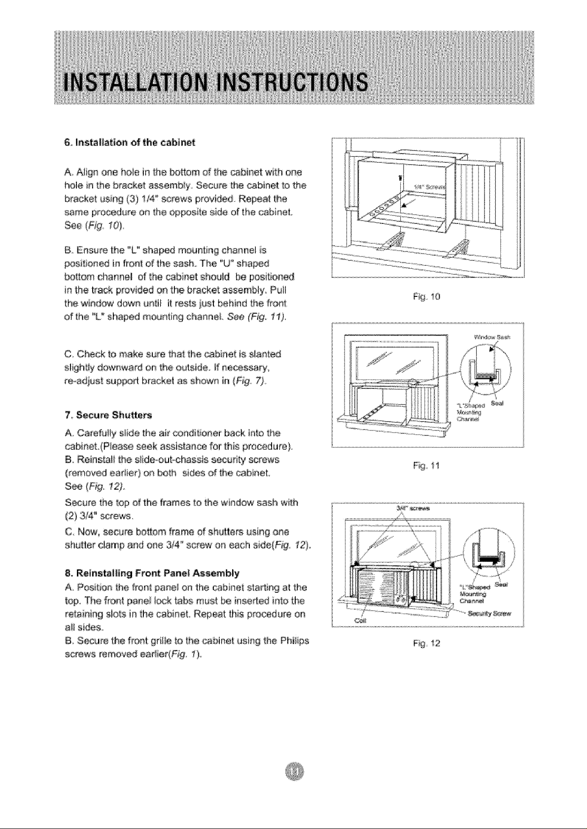
& Insta|_atten of _he cabinet
A Align one hole n the bottom d the cabinet with one
hole in Re bracket ass.embiy. Secure the caMn,et to the
bracket using (3) 114',sctewe provided Repeat the
same proc_ure o,r_the oppo_te side of the cabinet
See, (Fig, 10),
B Ensure the °U_shaped mounting channel is
posi_oned in freestof the sash. The '_U_'shaped
bottom channel d lhe cabinet should be positioned
in the track, provided oe the bracke_ assembly Put_
the wndow down G_ti_ it resLsiust behind the fron_
of the %? shaped mounting charlneL See (F_g. 1I),
C Check {o make sure that the cabinet is sleeted
s gh_ly dowr_wa_d on _e outside if ne_ssa_,
re-adjust euppoA bracket as shown in (F:_g,7)
7_ Secure Shu_ers
A Carefully s!tde '[he air (_r_ditioner ;back_ato the
cabinet (Piease seek assista;_ee for this procedure)
8 Re_rlstali _he sl_deoouFchassis security screws
(removed earlier) on bo_h sJ_es of the cabineL
see(F g
Secure the top of the _ames to tl_e window sash with
(2) 3/4_ screws
C Now, eecure boltom frame d abutters using oee
shutte_ _:Icmp and ef_e 3_4'_screw on each side(F_g., t2)_
8, Reinsta||ing Front Panel Assembly
A Position the f_ont pane_ on the cabi_et sta_Rg at the
top, The _ro#t par_e__ock_abs m_s| be ir_seded into the
rata ning slots ie the cabinet, Repeat this procedure on
ai! sides
B Secure the front gd!_e_,othe cabineI using the Phfl_ps
screws removed ea_iedF_g, 11),
_g 12
 Loading...