

Admiral (Kelon) AW-05CR1FHU, AW-05CR1FHUAAW, AW-08CR1FHU, AW-08DR1FHUAAW, AW-08DR1FHU Owner’s Manual
Room Air Conditioner
AireAc0ndici0nad0paraHabitaci0nes
Use and Care Manual
Manual de Uso y Mantenimiento
Thank you very much for purchasing an ,_:;!W|NT; Air Conditioner. Please read this Use and Care Manual
carefully before installing and using this appliance and keep this manual for future reference,
Muchas gracias por comprar un Aire Acondicionado _W=NT Lea atentamente el
Manual de Uso y Mantenimiento antes de instalar y utilizar este producto. Conserve este
manual para consultarlo en el futuro.
For service, call 1 877 465 3566
Para obtenerservicio t6cnico, Ilameal 1 877 465 3566
Table of Contents
Page
Introduction 2
Parts Identification 2
Electrical Specifications
Tips Before Installation
Installation Instructions
Operating Instructions
Care and Maintenance 13
Trouble Shooting Guide 14
Warranty 15
4
5
6
9
f ndice
Pagina
Introducci6n 16
Identificaci6n de las Piezas 16
Especificaciones Electricas 18
Consejos Antes de la Instalaci6n 19
Instrucciones de Instalaci6n 20
Instrucciones de Operaci6n 23
Cuidado y Mantenimiento 27
Gufa para la Soluci6n de Problemas 28
Garanti a 29
--1--
introduction /
Thank you for choosing this room air conditioner to cool your home. This USE AND CARE MANUAL
provides information necessary for the proper care and maintenance of your new room air conditioner.
If properly maintained, your air conditioner will give you many years of trouble free operation. To avoid
installation difficulties, read instructions completely before starting. This manual contains information for the
installation and operation of your room air conditioner.
i ! tioo¸
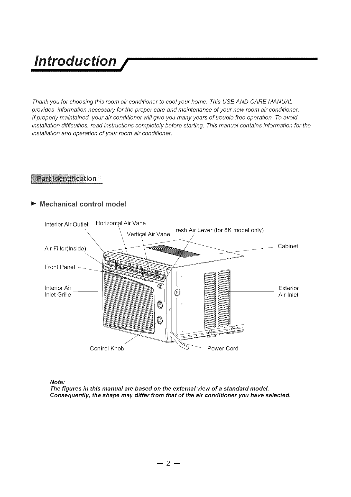
m,. Mechanica_ contro_ mode_
Interior Air Outlet
Air Filter(Inside)
Front Panel
Interior Air Exterior
Inlet Grille Air Inlet
Control Knob Power Cord
Note:
The figures in this manual are based on the external view of a standard model.
Consequently, the shape may differ from that of the air conditioner you have selected.
Air Vane
Vertical Air Vane
Fresh Air Lever (for 8K model only)
Cabinet
--2--
Introduction /
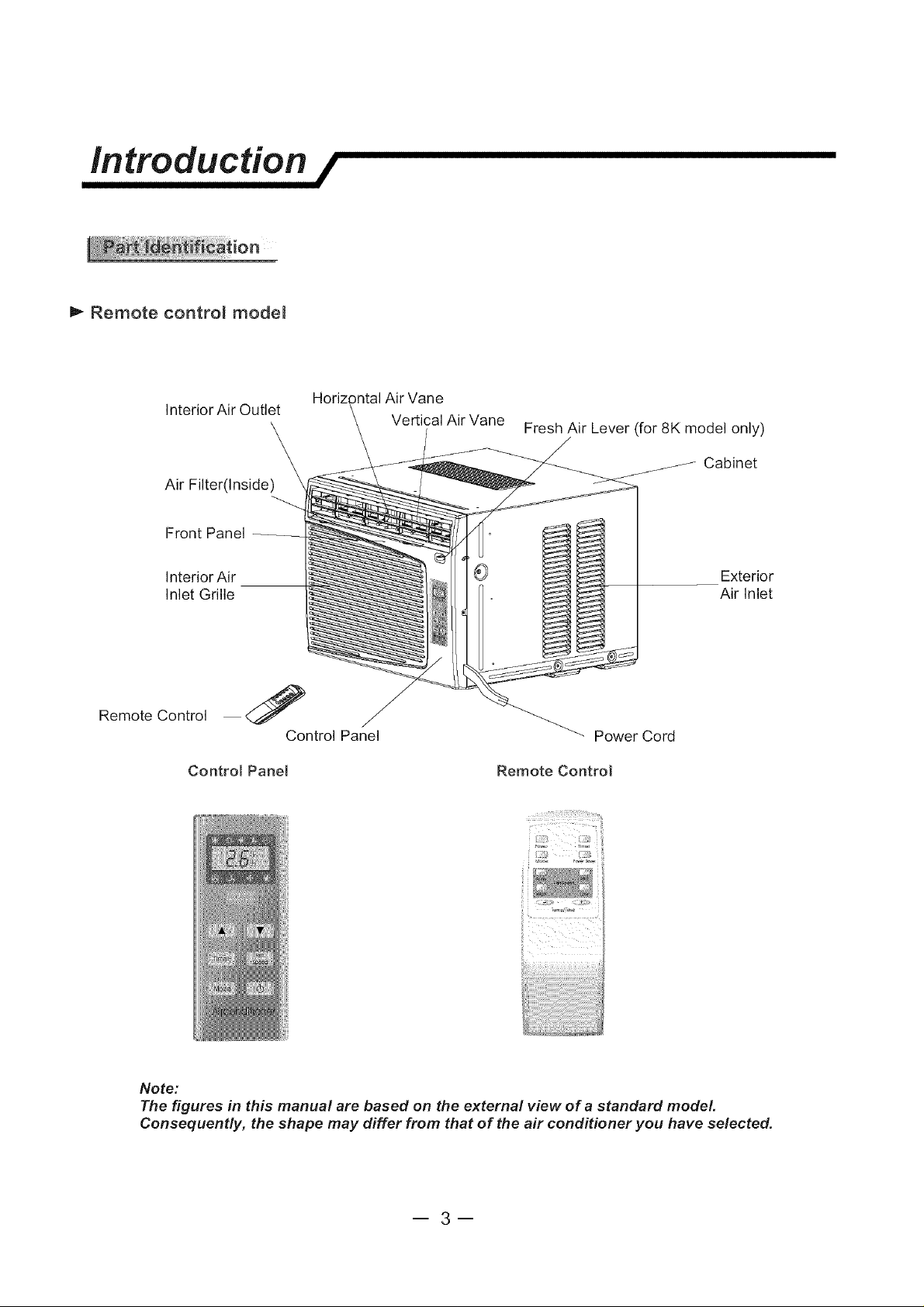
P- Remote contro_ mode_
Interior Air Outlet
Air Filter(Inside)
Front Panel
Interior Ai r
Inlet Grille
Remote Control
Control Panel
3ntal Air Vane
Control Panel
Vertical Air Vane
Fresh Air Lever (for 8K model only)
Cabinet
Exterior
Air Inlet
Power Cord
Remote Control
Note:
The figures in this manual are based on the external view of a standard model.
Consequently, the shape may differ from that of the air conditioner you have selected,
--3--
Electrical specifications /
1. All wiring must comply with local and national
electrical codes and must be installed by a
licensed electrician. Once you have any
questions regarding the following instructions,
contact a licensed electrician.
2. Check available power supply and resolve any
wiring problems BEFORE installing and operating
this unit.
3. For your safety and protection, this unit is
grounded through the power cord when
plugged into a matching wall outlet. If you are
not sure whether your wall outlet is properly
grounded, please consult a licensed
electrician.
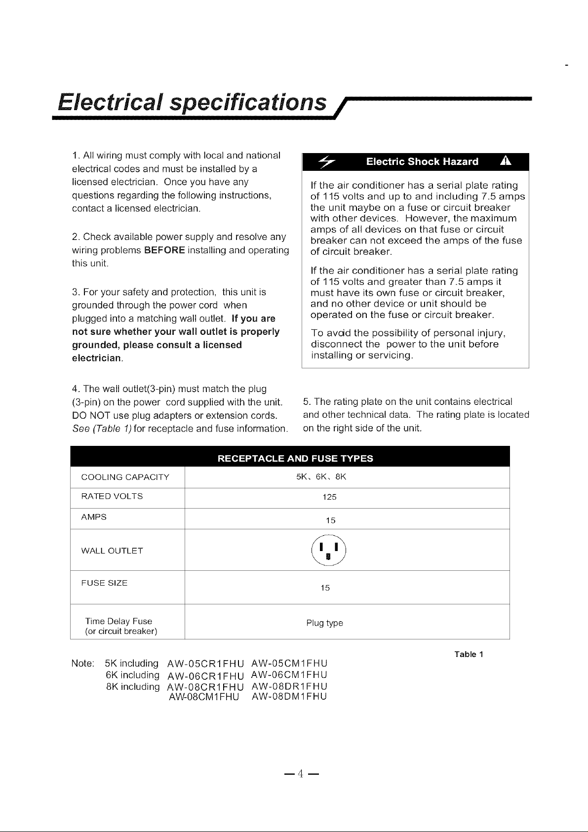
4. The wall outlet(3-pin) must match the plug
(3-pin) on the power cord supplied with the unit.
DO NOT use plug adapters or extension cords.
See (Table 1)for receptacle and fuse information.
If the air conditioner has a serial plate rating
of 115 volts and up to and including 7.5 amps
the unit maybe on a fuse or circuit breaker
with other devices. However, the maximum
amps of all devices on that fuse or circuit
breaker can not exceed the amps of the fuse
of circuit breaker.
If the air conditioner has a serial plate rating
of 115 volts and greater than 7.5 amps it
must have its own fuse or circuit breaker,
and no other device or unit should be
operated on the fuse or circuit breaker.
To avdd the possibility of personal injury,
disconnect the power to the unit before
installing or servicing.
5. The rating plate on the unit contains electrical
and other technical data. The rating plate is located
on the right side of the unit.
COOLING CAPACITY 5K. 6K. 8K
RATED VOLTS 125
AMPS 15
WALL OUTLET
FUSE SIZE 15
Time Delay Fuse Plug type
(or circuit breaker)
Note:
5K including
6K including
8K including
AW-05CR1FHU AW-05CM1FHU
AW-06CR1FHU AW-06CM1FHU
AW-08CR1FHU AW-08DR1FHU
AW-08CM1FHU AW-08DM1FHU
Table 1

Tips before installation /
Your RoomAir Conditioner unit is designed to
be highly efficient and save energy. Follow these
recommendations for greater efficiency.
1. Select thermostat setting that suits your
comfort needs and leave the thermostat at
that chosen setting.
2. The air filter is very efficient in removing airborne
particles. Keep the air filter clean. Typically, filter
should be cleaned once a month. More
frequent cleaning may be necessary depending
on outdoor and indoor air quality.
3. Use drapes, curtains, or shades to keep
direct sunlight from heating your room, but
DO NOT obstruct the air conditioner. Allow air to
circulate around the unit without obstructions.
4. Start your air conditioner before outdoor
air becomes hot and uncomfortable. This
avoids an initial period of discomfort while
the unit is cooling off the room.
5. When outdoor temperature is cool
enough, use HIGH or LOW FAN
only. This circulates indoor air, providing
some cooling comfort, and utilizes less
electricity than when operating on a
cooling setting.
Your RoomAir Conditioner was designed
for easy installation in a single or double-hung
window. NOTE: This unit is NOT designed for
vertical (slider type) windows.
To avoid installation/operating difficulties,
read the instructions thoroughly.
NOTE: Save the shipping carton and packing
materials for future storage or transport of the unit.
Please check the contents of the hardware kit
against the corresponding model check list, prior to
installation of the unit.
See fists below. (Fig. 1)
3/4"Screws (12)
2/5"Screws (8)
Seal(l)
Foam(1 )
Top Channel(1 )
factory installed
L Bracket(2)
_ Side Bracket(2)
Side Curtain RH(1)
Side Curtain LH(1)
Fig.1
NOTE: Surplus screw(s) for spare use.
Tools Needed for Window Installation
Screw drivers: Both Philips and flat head
Power drill: 1!8 inch diameter drill bit
Pencil
Measuring tape
Scissors
Carpenters level
--5--
Installation instructions /
F. Your unit was designed to evaporate condensation
under normal conditions. However, under extreme
Because the compressor is located on the
controls side of the unit (right side), this side
will be heavier and more awkward to manipulate.
Inadequate support on control side of the unit
can result in personal injury and damage to your
unit and property. Therefore, it is recommended
to have someone assist you during the installation
of this unit.
humidity conditions, excess condensation may cause
the base pan to overflow to the outside.
The unit should be installed where condensation
run-off cannot drip on pedestrians or neighboring
properties.
1. Select the Best Location
A. Your room air conditioner was designed to
fit easily into a single or double hung window. However,
since window designs vary, it may be necessary to
make some modifications for safe and proper
installation.
B. Make sure the window and frame are structurally
sound and free from dry and rotted wood.
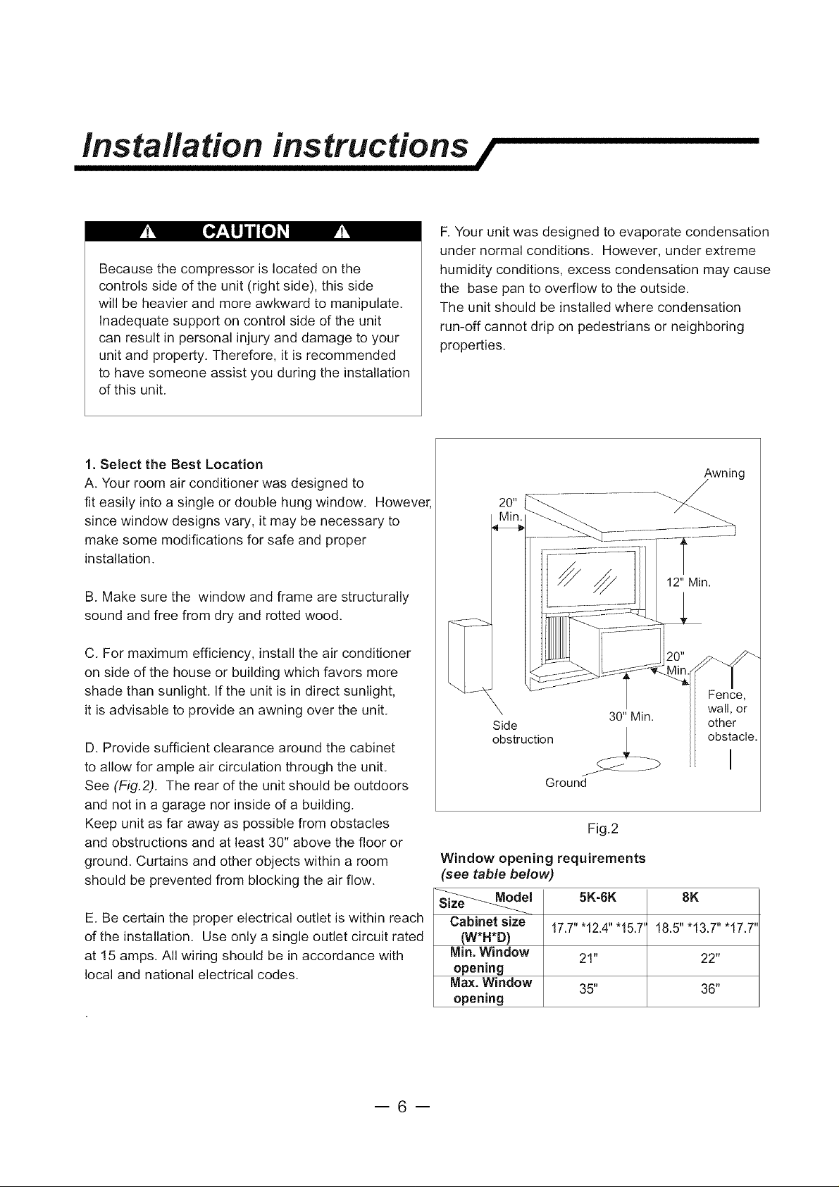
C. For maximum efficiency, install the air conditioner
on side of the house or building which favors more
shade than sunlight. If the unit is in direct sunlight,
it is advisable to provide an awning over the unit.
D. Provide sufficient clearance around the cabinet
to allow for ample air circulation through the unit.
See (Fig.2). The rear of the unit should be outdoors
and not in a garage nor inside of a building.
Keep unit as far away as possible from obstacles
and obstructions and at least 30" above the floor or
ground. Curtains and other objects within a room
should be prevented from blocking the air flow.
E. Be certain the proper electrical outlet is within reach
of the installation. Use only a single outlet circuit rated
at 15 amps. All wiring should be in accordance with
local and national electrical codes.
Awning
12" Min.
Fence,
Side other
obstruction _ obstacle,i
Ground
Window opening requirements
(see table below)
Cabinet size 17.7""12A" "15.7' 18.5" "13.7" "17.7'
(W*H*D)
Min. Window 21" 22"
opening
Max. Window 35" 36"
opening
30" Min.
Fig.2
5K-6K 8K
wall, or
--6--
Installation instructions /
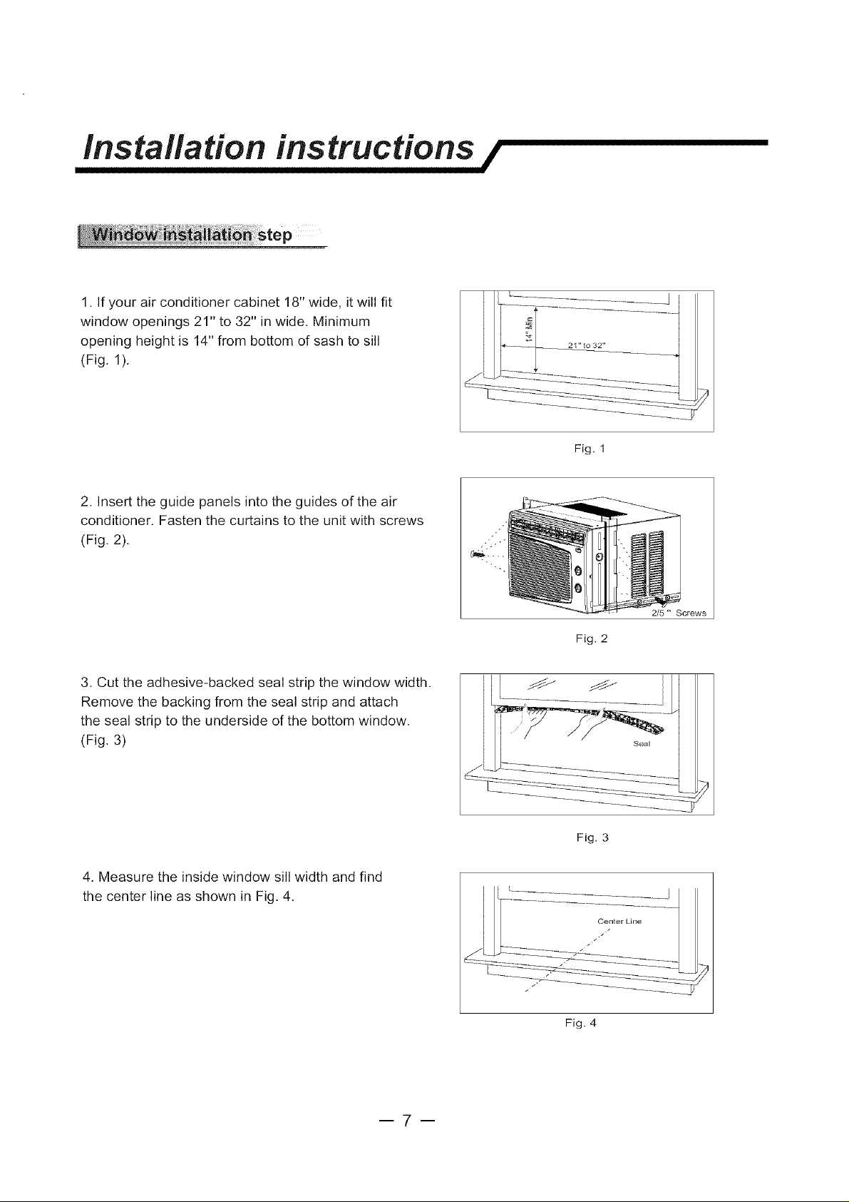
1. If your air conditioner cabinet 18" wide, it will fit
window openings 21" to 32" in wide. Minimum
opening height is 14" from bottom of sash to sill
(Fig. 1).
2. Insert the guide panels into the guides of the air
conditioner. Fasten the curtains to the unit with screws
(Fig. 2).
Fig. 1
3. Cut the adhesive-backed seal strip the window width.
Remove the backing from the seal strip and attach
the seal strip to the underside of the bottom window.
(Fig. 3)
4. Measure the inside window sill width and find
the center line as shown in Fig. 4.
2/5 " Screws
Fig. 2
Fig. 3
Fig. 4
--7--
Installation instructions /
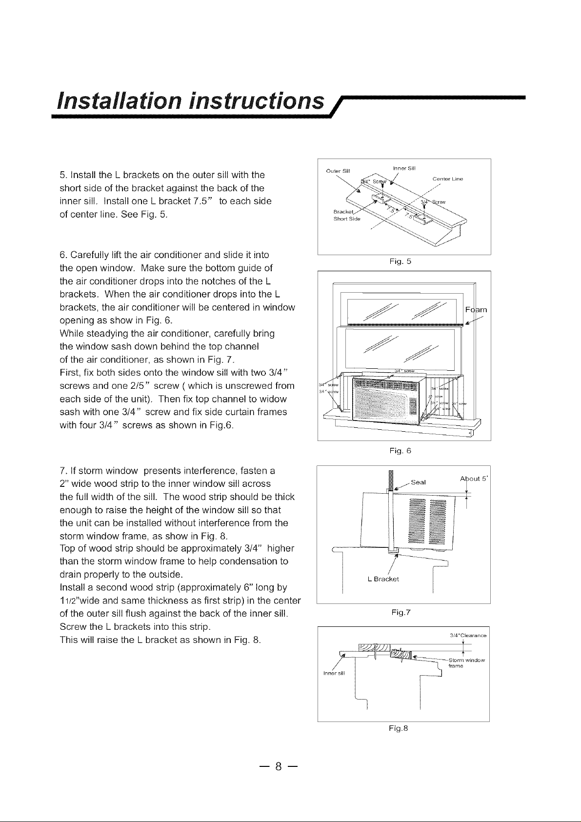
5. Install the L brackets on the outer sill with the
short side of the bracket against the back of the
inner sill. Install one L bracket 7.5" to each side
of center line. See Fig. 5.
6. Carefully lift the air conditioner and slide it into
the open window. Make sure the bottom guide of
the air conditioner drops into the notches of the L
brackets. When the air conditioner drops into the L
brackets, the air conditioner will be centered in window
opening as show in Fig. 6.
While steadying the air conditioner, carefully bring
the window sash down behind the top channel
of the air conditioner, as shown in Fig. 7.
First, fix both sides onto the window sill with two 3/4"
screws and one 2/5" screw ( which is unscrewed from
each side of the unit). Then fix top channel to widow
sash with one 3/4" screw and fix side curtain frames
with four 3/4" screws as shown in Fig.6.
Outer Sill
Short Side
Inner Sill
Center Line
Fig. 5
F(
7. If storm window presents interference, fasten a
2" wide wood strip to the inner window sill across
the full width of the sill. The wood strip should be thick
enough to raise the height of the window sill so that
the unit can be installed without interference from the
storm window frame, as show in Fig. 8.
Top of wood strip should be approximately 3/4" higher
than the storm window frame to help condensation to
drain properly to the outside.
Install a second wood strip (approximately 6" long by
11/2"wide and same thickness as first strip) in the center
of the outer sill flush against the back of the inner sill.
Screw the L brackets into this strip.
This will raise the L bracket as shown in Fig. 8.
Fig. 6
L Brac_
Fig.7
3/4"Clearance
Fig.8
--8--
Operating instructions /
I_Mechanical control model
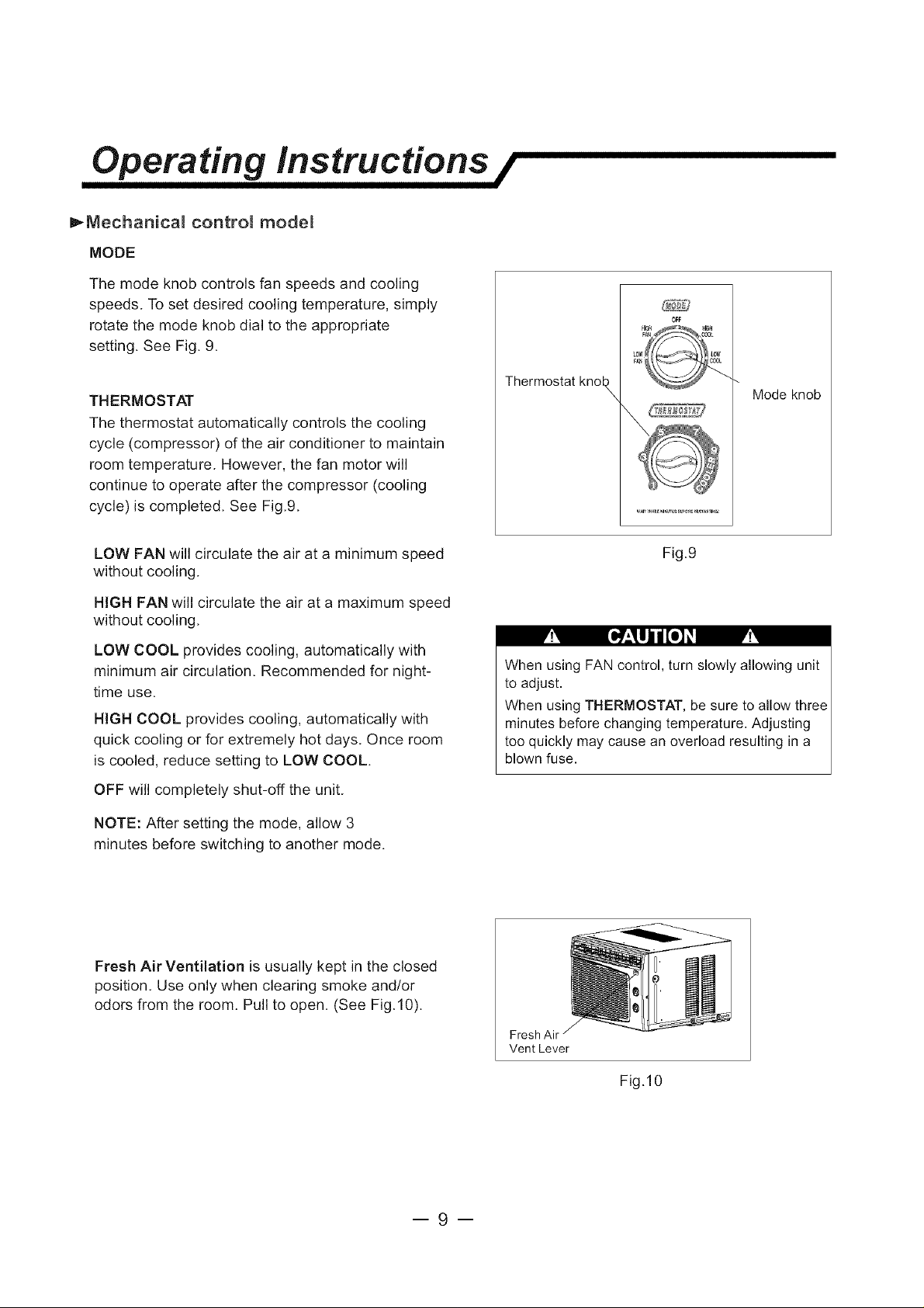
MODE
The mode knob controls fan speeds and cooling
speeds. To set desired cooling temperature, simply
rotate the mode knob dial to the appropriate
setting. See Fig. 9.
OFF
THERMOSTAT
The thermostat automatically controls the cooling
cycle (compressor) of the air conditioner to maintain
room temperature. However, the fan motor will
continue to operate after the compressor (cooling
cycle) is completed. See Fig.9.
LOW FAN will circulate the air at a minimum speed
without cooling.
HIGH FAN will circulate the air at a maximum speed
without cooling.
LOW COOL provides cooling, automatically with
minimum air circulation. Recommended for night-
time use.
HIGH COOL provides cooling, automatically with
quick cooling or for extremely hot days. Once room
is cooled, reduce setting to LOW COOL.
OFF will completely shut-off the unit.
NOTE: After setting the mode, allow 3
minutes before switching to another mode.
Thermostat knol_
Mode knob
Fig.9
When using FAN control, turn slowly allowing unit
to adjust.
When using THERMOSTAT, be sure to allow three
minutes before changing temperature. Adjusting
too quickly may cause an overload resulting in a
blown fuse.
Fresh Air Ventilation is usually kept in the closed
position. Use only when clearing smoke and/or
odors from the room. Pull to open. (See Fig.10).
--9--
Fresh Air
Vent Lever
Fig.10
 Loading...