

Admiral (Kelon) AAWV-10CR1FAU Owner’s Manual
AC 12 i0 8 6 MAN final 3/2/05 12:55 PM Page i
SLIDERCASEMENTROOMAiR CONDiTiONER
Use and Care Manual
AAWV-12CR1FAU
AAWV-10CR1FAU
AAWV-08CR1 FAU
AAWV-06CRIFAU
Thank you for purchasing an Admiral _room air conditioner. Please read this "Use and Care Manual" carefully
before installing and using this appliance. Keep this manual for future reference.
M <hasef:_a_asp> cor_ _a_ a e acor/dco a< )Admiral Leaae/!amer_te_ Man a de _soy
Ma e_ /_ er_;Io a esde r_;slaa_y t za eslep_od clo Censeveesle_a_ a palace s a_oe_ e [ Iso
For Service Call 1 877 465 3566
< <_ , ,
:_4 V , ,; [,C <,, _iI @ <:,_ / qO:._,.s._u,
Page
Introduction .................................................. 2
Parts Identification ............................................. 2
Air Conditioner Safety ......................................... 3-4
Electrical Specifications
Tips Before Installation
Installation Instructions
Operating Instructions
Care and Maintenance
Troubleshooting Guide
Warranty
Introducci6n ................................................. 15
Identificaci6n de las Piezas ..................................... 15
Especificaciones EI6ctricas ..................................... 16
................................................... 14
....................................... 7-8
....................................... 9-11
......................................... 12
......................................... 13
Page
Consejos Antes dela Instalaci6n .................................. 17
Instrucciones de Instalaci6n .................................. 18-19
Instrucciones de Operaci6n .................................. 20-22
Cuidado y Mantenimiento ....................................... 23
Guia para la Soluci6n de Problemas ............................... 24
Garantia .................................................... 25
INTRq
Thank you for choosing this room air conditioner to cool your home. This USE AND CARE MANUAL
provides information necessary for the proper care and maintenance of your new room air conditioner.
If properly maintained, your air conditioner will give you many years of trouble free operation. To avoid
instaflation difficulties, read instructions completely before starting. This manual contains information for the
instaflation and operation of your room air conditioner.
_)_ ©_F ' "_ °°_ _E_D _1 s¸_
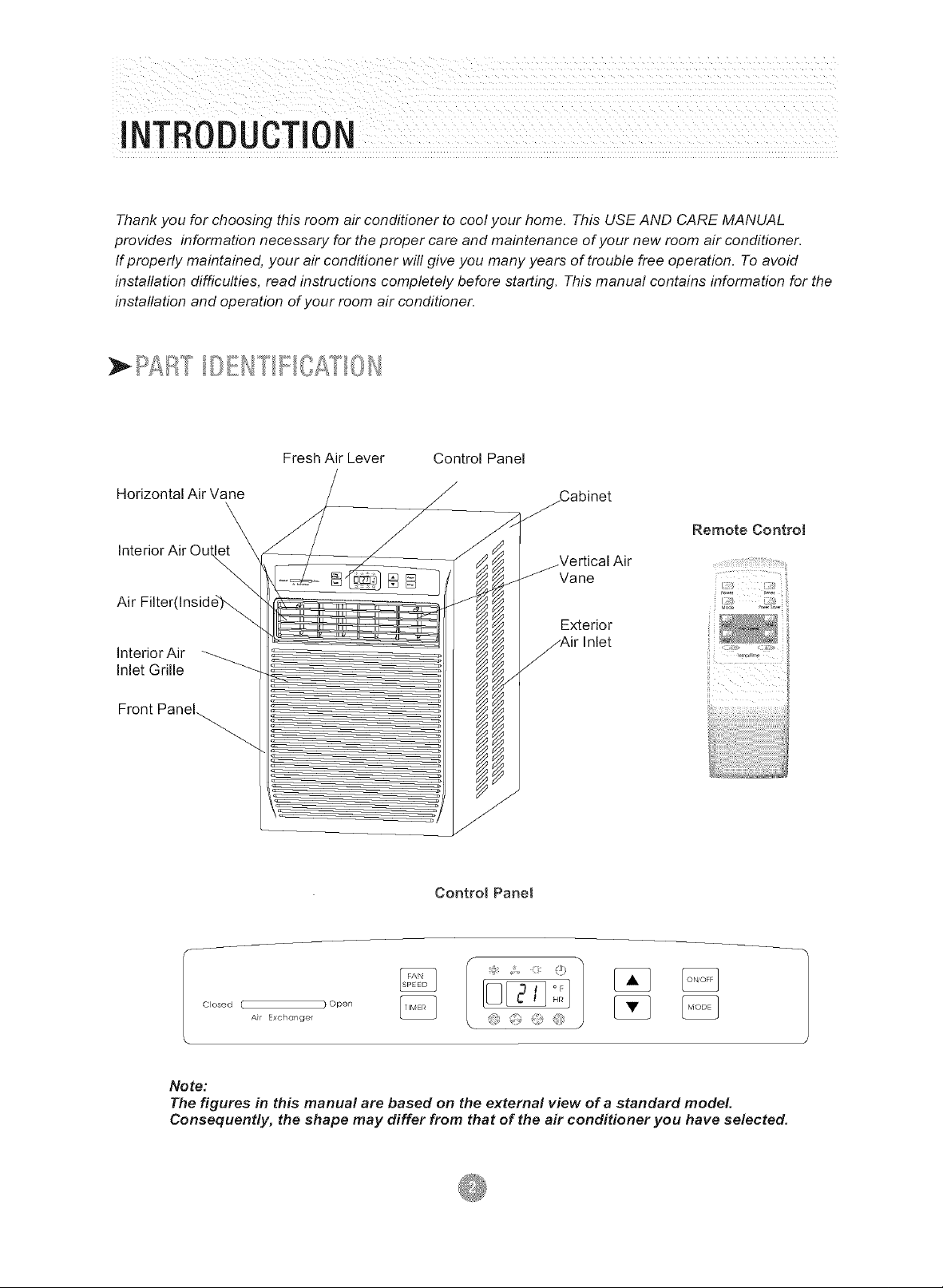
Fresh Air Lever Control Panel
Horizontal Air Vane
Interior Air Ou
Air Filter(Inside).._
Interior Air
Inlet Grille
Front Panel_
Y
Remote Controt
Vane
Exterior
i
i
Control Panel
Closed [ ) Open
Air Exchanger
Note:
The figures in this manual are based on the external view of a standard model.
Consequently, the shape may differ from that of the air conditioner you have selected,
AIR CONDITIq
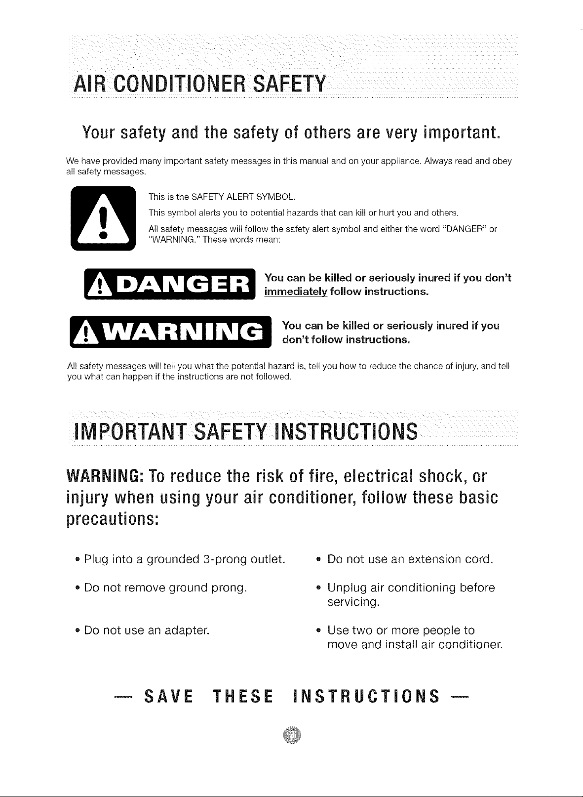
Yoursafety and the safety of others are very important.
We have provided many important safety messages in this manual and on your appliance. Always read and obey
all safety messages.
This is the SAFETY ALERT SYMBOL.
This symbol alerts you to potential hazards that can kill or hurt you and others.
All safety messages will follow the safety alert symbol and either the word "DANGER" or
"WARNING." These words mean:
You can be killed or seriously inured if you don't
immediately follow instructions.
You can be killed or seriously inured if you
don't follow instructions.
All safety messages will tell you what the potential hazard is, tell you how to reduce the chance of injury, and tell
you what can happen if the instructions are not followed.
!IVlPOBTANTSAFETYiNSTBUCTIONS
WARNING:Toreduce the risk of fire, electrical shock, or
injury when using your air conditioner, follow these basic
precautions:
• Plug into a grounded 3-prong outlet.
• Do not remove ground prong.
Do not use an adapter.
m SAVE THESE INSTRUCTIONS
Do not use an extension cord.
Unplug air conditioning before
servicing.
Use two or more people to
move and install air conditioner.
! NSTALLATI0N REQUIREMENTS
• The portable air conditioner should be connected
to a 115 V, 60 Hz, 15- or 20-amp fused 3-prong
grounded outlet.
The use of a time-delay fuse or time-delay circuit
breaker is recommended.
All wiring must comply with local and national
electrical codes and be installed by a qualified
electrician. If you have any questions, contact
a qualified electrician.
ELECTRIC SHOCK HAZARD
Plug into a grounded 3-prong outlet
• Do not remove ground prong.
Do not use an adapter.
Do not use an extension cord.
• Failure to follow these instructions can
result in death, fire, or electrical shock.
LI m m ml_li m m m m I_
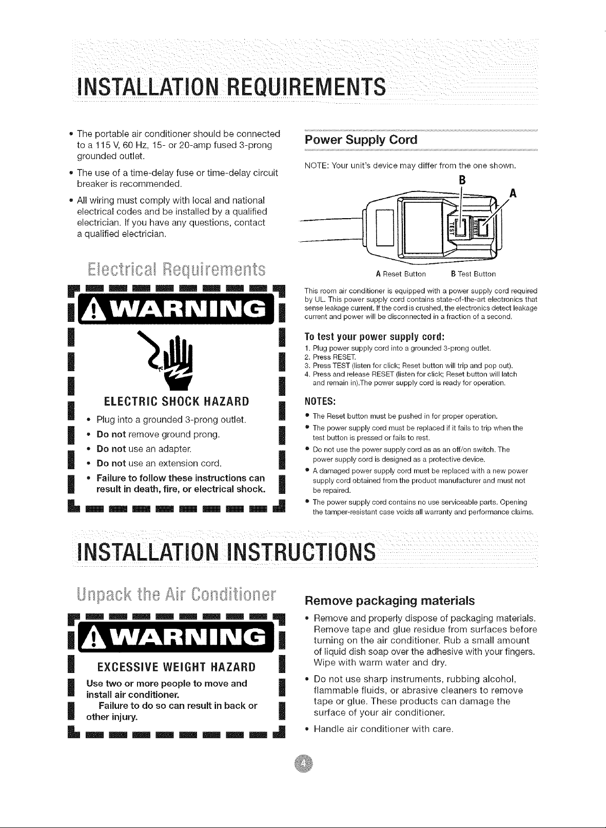
Power Supply Cord
NOTE:Your unit's device may differ from the one shown.
B
AReset Button BTest Button
This room air conditioner is equipped with a power supply cord required
by UL This power supply cord contains state-of-the-art electronics that
sense leakage current. If the cord is crushed, the electronics detect leakage
current and power will be disconnected in a fraction of a second.
To test your power supply cord:
|
1. Plug power supply cord into a grounded 3-prong outlet.
2. Press RESET.
|
3. Press TEST (listen for click; Reset button will trip and pop out).
4. Press and release RESET (listen for click; Reset button will latch
|
|
|
|
|
and remain in).The power supply cord is ready for operation.
NOTES:
• The Reset button must be pushed in for proper operation.
• The power supply cord must be replaced if it fails to trip when the
test button is pressed or fails to rest,
• Do not use the power supply cord as as an off/on switch, The
power supply cord is designed as a protective device,
• A damaged power supply cord must be replaced with a new power
supply cord obtained from the product manufacturer and must not
be repaired.
• The power supply cord contains no use serviceable parts, Opening
the tamper-resistant case voids all warranty and performance claims.
INSTALLATIONINSTRUCTION
Remove packaging materials
Remove and properly dispose of packaging materials.
Remove tape and glue residue from surfaces before
turning on the air conditioner. Rub a small amount
of liquid dish soap over the adhesive with your fingers.
EXCESSIVE WEIGHT HAZARD I
Use two or more people to move and I
install air conditioner.
Failure to do so can result in back or I
other injury.
Wipe with warm water and dry.
Do not use sharp instruments, rubbing alcohol,
flammable fluids, or abrasive cleaners to remove
tape or glue. These products can damage the
surface of your air conditioner.
Handle air conditioner with care.
ELECTRICALSPECiFiCAT!0NS
1. All wiring must comply with local and national
electrical codes and must be installed by a
licensed electrician. Once you have any questions
regarding the following instructions, contact a
licensed electrician.
2. Check available power supply and resolve any
wiring problems BEFORE installing and operating
this unit.
3. For your safety and protection. This unit is
grounded through the power cord when
plugged into a matching wall outlet. If you are
not sure whether your wall outlet is properly
grounded, please consult a licensed
electrician.
If the air conditioner has a serial plate rating
of 115 volts and up to and including 7.5 amps
the unit maybe on a fuse or circuit breaker
with other devices. However, the maximum
amps of all devices on that fuse or circuit
breaker can not exceed the amps of the fuse
of circuit breaker.
If the air conditioner has a serial plate rating
of 115 volts and greater than 7.5 amps it
must have its own fuse or circuit breaker,
and no other device or unit should be
operated on the fuse or circuit breaker.
To avoid the possibility of personal injury,
disconnect power to the unit before installing
or servicing.
4. The wall outlet(3-pin) must match the plug
(3-pin) on the service cord supplied with the unit.
DO NOT use plug adapters or extension cord.
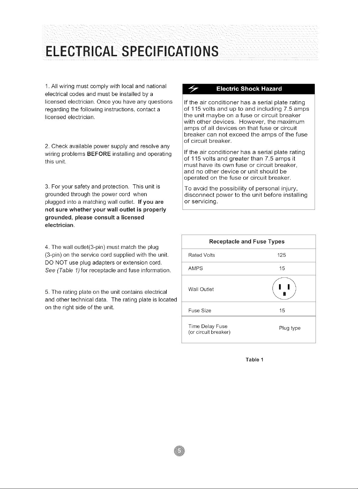
See (Table 1)for receptacle and fuse information.
5. The rating plate on the unit contains electrical
and other technical data. The rating plate is located
on the right side of the unit.
Receptacle and Fuse Types
Rated Volts 125
AMPS 15
Wall Outlet
Fuse Size 15
Time Delay Fuse Plug type
(or circuit breaker)
Table 1
TIPS BEFOREINSTALLATION
Your RoomAir Conditioner unit is designed to
be highly efficient and save energy. Follow these
recommendations for greater efficiency.
1. Select the thermostat setting that suits your
comfort needs and leave the thermostat at
that chosen setting.
2. The filter is very efficient in removing airborne
particles. Keep air filter clean. Normally, filter
should be cleaned once a month. More
frequent cleaning may be necessary depending
on outdoor and indoor air quality.
3. Use drapes, curtains, or shades to keep
direct sunlight from heating your room, but
DO NOT obstruct the air conditioner.Allow air to
circulate around the unit without obstructions.
4. Start your air conditioner before outdoor
air becomes hot and uncomfortable. This
avoids an initial period of discomfort while
the unit is cooling off the room.
5. When outdoor temperature is cool
enough, use HIGH or LOW FAN
only. This circulates indoor air, providing
some cooling comfort, and utilizes less
electricity than when operating on a
cooling setting.
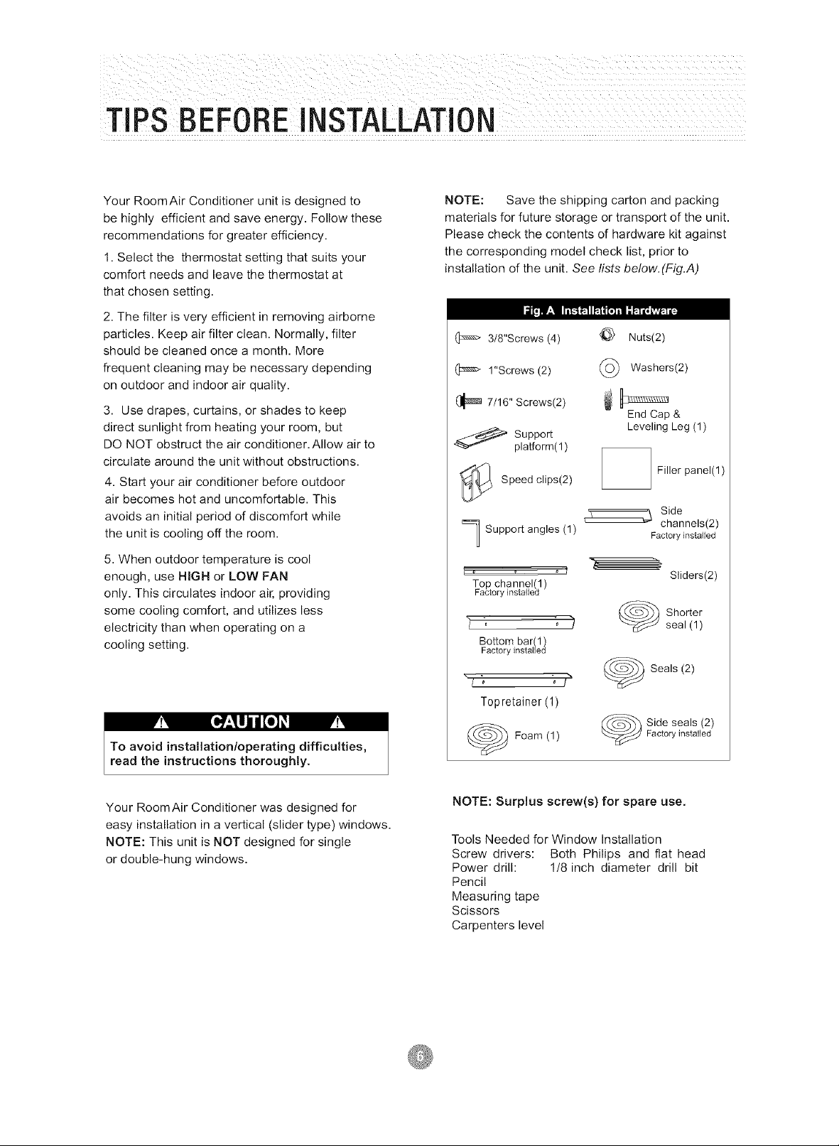
NOTE: Save the shipping carton and packing
materials for future storage or transport of the unit.
Please check the contents of hardware kit against
the corresponding model check list, prior to
installation of the unit. See lists below.(Fig.A)
I_1_1r:l _ _
3/8"Screws (4)
1"Screws(2)
(_ 7/16" Screws(2)
Nuts(2)
(_ Washers(2)
End Cap &
LevelingLeg (1)
_ Support
platform(1)
Filler panel(l)
_ Speed clips(2)
Side
channels(2)
] Support angles(1)
Top channel(I)
Factory installed
"L , )
Bottombar 1)
Factory nsta ed
Factory installed
Sliders(2)
Shorter
seal (1)
F!Y
To avoid installation/operating difficulties,
read the instructions thoroughly.
Your RoomAir Conditioner was designed for
easy installation in a vertical (slider type) windows.
NOTE: This unit is NOT designed for single
or double-hung windows.
"L_ J"
Seals (2)
Topretainer (1)
Factory installed
Foam (1)
Side seals (2)
NOTE: Surplus screw(s) for spare use.
Tools Needed for Window Installation
Screw drivers: Both Philips and flat head
Power drill: I/8 inch diameter drill bit
Pencil
Measuring tape
Scissors
Carpenters level
INSTALLATIONINSTRUCTIONS
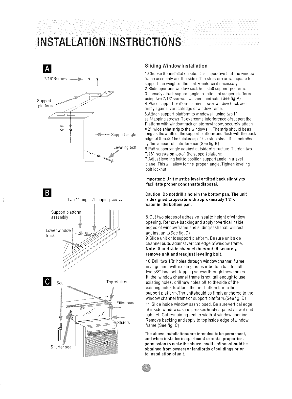
D
7/16"Screws
Support _,j_, "_' 1:?::1:.....
ptatform ......:::::
f_@_) _&¢ // '_ ............Support angle
.......::J.
I Leveling bolt
D
Two 1"long self-tapping screws
Support platform
assembly
Lowerwindow
track
Topretainer
Shorter seal
Filer panel
Sliders
Sliding Windowlnstallation
1.Choose theinstatIation site. It is imperative that the window
frame assembly andthe side ofthe structure areadequate to
support the weightof the unit. Reinforce if necessary.
2.Slide openone window sashto install support platform.
3.Loosely attach support angle tobottom of supportplatform
using two 7/16"screws, washers andnuts. (Seefig. A)
4.Place support platform against lower window track and
firmly against verticaledge of windowfrarne.
5.Attach support platform to windowsill using two1"
self-tapping screws. Toovercome interference ofsupport the
Platform with windowtrack or stormwindow, securely attach
a2" wide shim stripto the windowsill. Thestrip should beas
long as thewidth of thesupport platform and flush withthe back
edge of thesiIbThe thickness of the strip should be controlled
bythe amountof interference.(See fig. B)
&Pull supportangIe against outsideof structure. Tighten two
7/16" screws on topof the supportpIatform.
7.Adjust leveling bottto position supportangle inalevel
plane. Thiswill allow forthe proper angle.Tighten leveling
bolt tocknut.
Important: Unit must be level ortilted back slightlyto
facilitate proper condensatedisposal.
Caution: Do notdrill a holein the bottompan. The unit
is designed tooperate with approximately 1/2" of
water in thebottom pan.
8.Cut two piecesof adhesive sealto height ofwindow
opening. Remove backingand apply tovertical inside
edges of windowframe and sliding sash that will rest
against unit.(See fig. C)
9.Slide unit ontosupport platform. Besure unit side
channel butts againstvertical edge ofwindow frame.
Note: If unitside channel doesnot fit securely,
remove unit and readjust leveling bolt.
10.Drill two 1/8" holes through windowchannel frame
in alignment with existing holes in bottom bar. Install
two 3/8" long self-tapping screwsthrough these holes.
If the windowchannel frame isnot tall enoughto use
existing holes, drill new holes off to theside of the
existing holes toattach the unitbottom bar tothe
support platform.The unitshould be firmlyanchored to the
window channel frameor support platform.(Seefig. D)
11.Slideinside window sash closed. Be surevertical edge
of inside windowsash is pressed firmly against sideof unit
cabinet. Cut remaining seal to width of window opening.
Remove backing andapply to topinside edge ofwindow
frame.(See fig. C)
The above installationsare intended tobe permanent,
and when installed in apartment orrental properties,
permission to makethe above modificationsshould be
obtained from ownersor landlords of buildings prior
to installation of unit.
INSTALLATIONINSTRUCTIONS
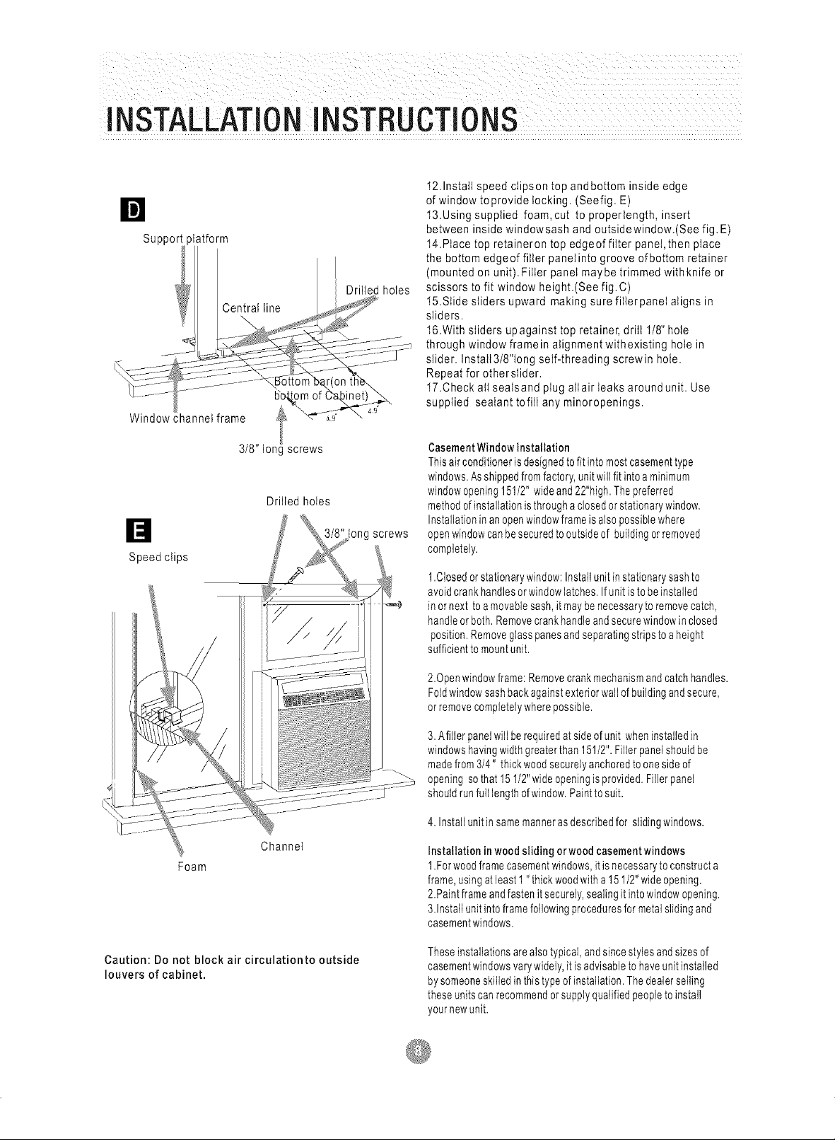
12.1nstaIlspeed cIipson top andbottorn inside edge
of window toprovide locking. (Seefig. E)
13.Using supplied foam,cut to properlength, insert
Support )latform
Drilled holes
Central line
"6"0_om of
Window channel frame _t_
between inside windowsash and outsidewindow.(See fig. E)
14.PIacetop retaineron top edgeof fiIter panel,then place
the bottom edgeof filler panel into groove ofbottorn retainer
(mounted on unit).Filler panel maybe trimmed withknife or
scissors to fit window height.(See fig.C)
15.Slide sliders upward making sure fillerpanel aligns in
sliders.
16.With sliders upagainst top retainer, drill I/8" hole
through window framein alignment with existing hole in
slider. Instatt3/8"long self-threading screwin hole.
Repeatfor othersIider.
17.Check all seatsand plug allair leaks aroundunit. Use
supplied sealant to% any minoropenings.
Speed clips
Foam
3/8" Ion_ screws
Drilled holes
Channel
!ong screws
CasementWindowInstallation
Thisairconditionerisdesignedto fitinto mostcasementtype
windows.Asshippedfromfactory,unitwillfitintoaminimum
windowopening151/2"wideand22"high.Thepreferred
methodofinstallationisthroughaclosedorstationarywindow.
Installationinanopenwindowframeisalsopossiblewhere
openwindowcanbesecuredtooutsideof buildingorremoved
completely.
1.Closedorstationarywindow:Installunitinstationarysashto
avoidcrankhandlesorwindowlatches.Ifunitistobeinstalled
in ornexttoamovablesash,it maybenecessarytoremovecatch,
handleorboth.Removecrankhandleandsecurewindowinclosed
position.Removeglasspanesandseparatingstripsto aheight
sufficienttomountunit.
2.0penwindowframe:Removecrankmechanismandcatchhandles.
Foldwindowsashbackagainstexteriorwallof buildingandsecure,
orremovecompletelywherepossible.
3.Afillerpanelwillberequiredat sideofunit wheninstalledin
windowshavingwidthgreaterthan151/2".Fillerpanelshouldbe
madefrom3/4" thickwoodsecurelyanchoredto onesideof
openingsothat151/2"wideopeningisprovided.Fillerpanel
shouldrunfull lengthofwindow.Painttosuit.
4.Installunitinsamemannerasdescribedfor slidingwindows.
Installationinwoodsliding orwood casementwindows
1.Forwoodframecasementwindows,itisnecessarytoconstructa
frame,usingatleast1"thickwoodwitha151/2"wideopening.
2.Paintframeandfastenitsecurely,sealingitintowindowopening.
3.Installunitintoframefollowingproceduresformetalslidingand
casementwindows.
Caution: Do not block air circulationto outside
louvers of cabinet.
Theseinstallationsarealsotypical,andsincestylesandsizesof
casementwindowsvarywidely,itis advisableto haveunitinstalled
bysomeoneskilledinthistypeofinstallation.Thedealerselling
theseunitscanrecommendorsupplyqualifiedpeopletoinstall
yournewunit.
 Loading...