

Admiral (Kelon) AAW-12CR1FHU, AAW-18CR3FHU, AAW-24DR3FHU, AAW-18DR3FHU, AAW-12DR3FHU Owner’s Manual
...
miral°
Room Air Conditioner
Aire Acondicionado para Habitaciones
t] i i i i t] }]][]][]][][
Use an Care Manual
Manual de Uso y Mantenimiento
Thank you very much for purchasing an Admiral Air Conditioner. Please read this Use and Care Manual
carefully before installing and using this appliance and keep this manual for future reference.
Muchas gracias pot comprar un AireAcondicionado Admiral. Lea atentamenteel
Manual de Uso y Mantenimiento antes de instalary utilizar este producto. Conserve este
manual para consultarlo en el futuro.
For services, call 1 877 465 3566
Para obtenerservicio t6cnico, Ilameal 1 877 4653566

Table of Contents
Page
Introd uction 2
Parts Identification 2
Electrical Specifications 4
Tips Before Installation 5
Installation Instructions 6
Operating Instructions 11
Care and Maintenance 15
Trouble Shooting Guide 16
Warranty 17
ndice
Pdgina
Introducci6n 18
Identificaci6n de las Piezas
Especificaciones EI6ctricas
Consejos Antes de la Instalaci6n 21
Instrucciones de Instalaci6n ...................................................................................................
Instrucciones de Operaci6n 27
Cuidado y Mantenimiento 31
18
20
Gu_a para la Soluci6n de Problemas 32
Garanti a 33
--1--
introduction /
Thank you for choosing this room air conditioner to cool your home. This USE AND CARE MANUAL
provides information necessary for the proper care and maintenance of your new room air conditioner.
If properly maintained, your air conditioner will give you many years of trouble free operation. To avoid
installation difficulties, read instructions completely before starting. This manual contains information for the
installation and operation of your room air conditioner.
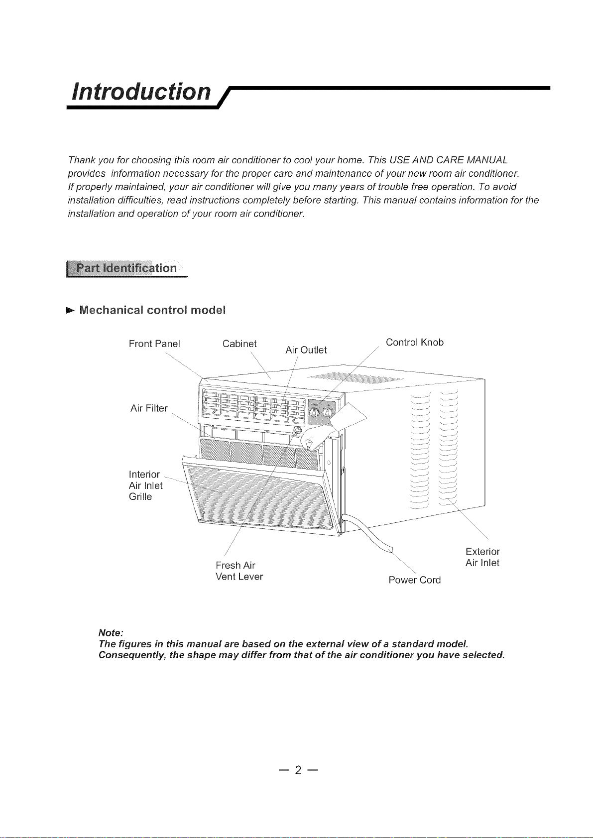
t,- Mechanical controm modem
Front Panel Cabinet Air Outlet /_ Control Knob
/
Air Filter
4
Interior
Air Inlet
Grille
,/ Exterior
Fresh Air \.. Air Inlet
\\
\
Vent Lever Power Cord
Note:
The figures in this manual are based on the external view of a standard model.
Consequently, the shape may differ from that of the air conditioner you have selected.
m2m
introduction /
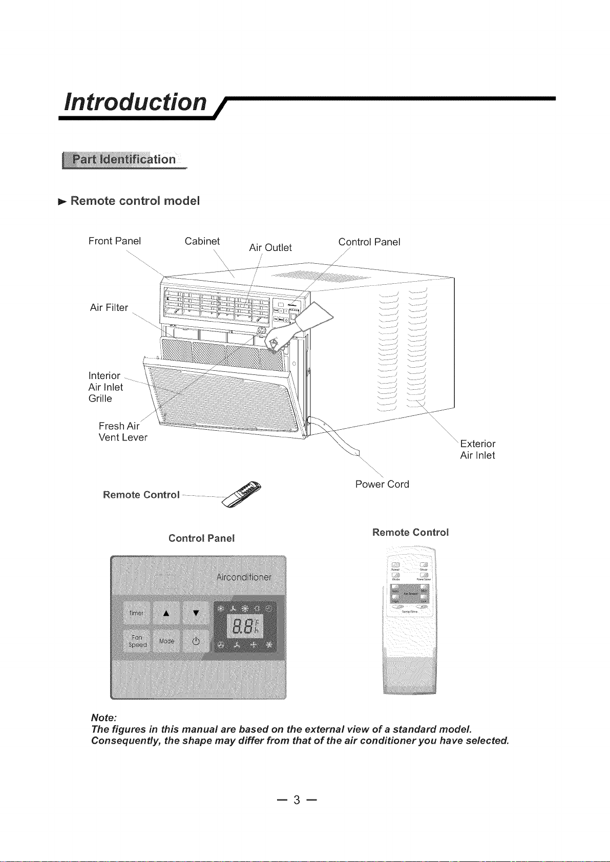
m,-Remote control modem
Front Panel Cabinet
Air Filter
Interior
Air Inlet
Grille
Fresh Air
S
Vent Lever
Remote Contro( ........
Control Pane(
Air Outlet
/
//
Control Panel
/
/
/
po-_wwerCord
Remote Contro(
Exterior
Air Inlet
J:#i;!,
iiii
Note:
The figures in this manual are based on the external view of a standard model.
Consequently, the shape may differ from that of the air conditioner you have selected.
m3m
Electrical specifications /
1. All wiring must comply with local and national
electrical codes and must be installed by a
licenced electrician. If you have any questions
regarding the following instructions, contact a
licenced electrician.
2. Check available power supply and resolve any
wiring problems BEFORE installing and operating
this unit.
If the air conditioner has a serial plate rating
of 115 volts and up to and including 7.5 amps,
the unit maybe on a fuse or circuit breaker
with other devices. However, the maximum
amps on all devices for that fuse or circuit
breaker can not exceed the amps of the fuse
for the circuit breaker.
3. For your safety and protection, this unit is
grounded through the power cord when
plugged into a matching wall outlet. If you are
not sure whether your wall outlet is properly
grounded, please consult a licenced
electrician.
4. The wall outlet (3-pin) must match the plug
(3-pin) on the power cord supplied with the unit.
DO NOT use plug adapters or extension cords.
See (Table 1)for receptacle and fuse information.
5. The rating plate on the unit contains electrical
and other technical data. The rating plate is
located on the right side of the unit. Make sure
to use the correct power supply according to the
rating plate of your air conditioner.
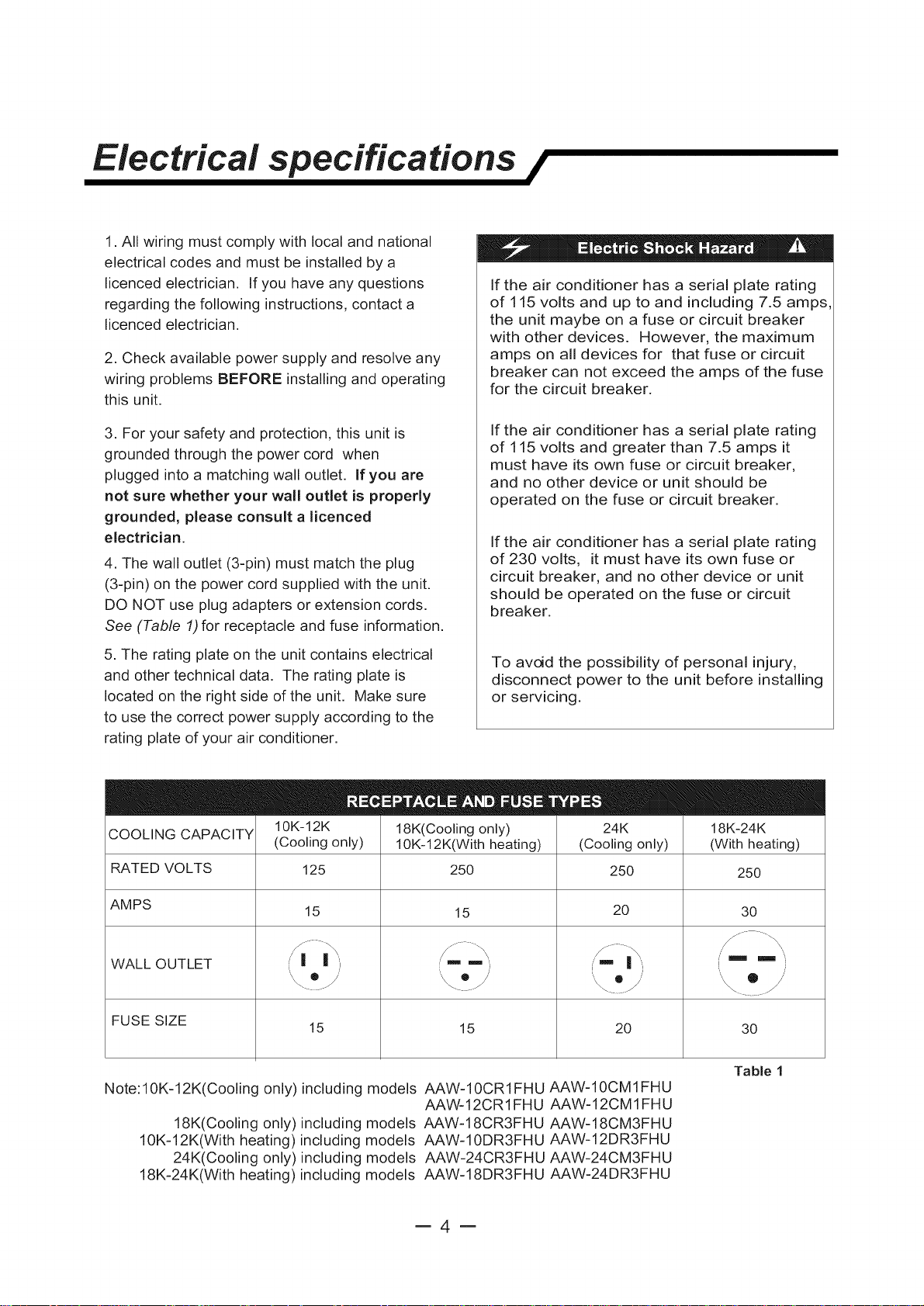
COOLING CAPACITY
RATED VOLTS 125 250
10K-12K
(Cooling only)
18K(Cooling only) 24K
10K-12K(With heating) (Cooling only)
If the air conditioner has a serial plate rating
of 115 volts and greater than 7.5 amps it
must have its own fuse or circuit breaker,
and no other device or unit should be
operated on the fuse or circuit breaker.
If the air conditioner has a serial plate rating
of 230 volts, it must have its own fuse or
circuit breaker, and no other device or unit
should be operated on the fuse or circuit
breaker.
To avoid the possibility of personal injury,
disconnect power to the unit before installing
or servicing.
18K-24K
(With heating)
250 250
AMPS 15 30
WALL OUTLET i m m .
FUSE SIZE
Note: 10K=12K(Cooling only) including models AAW-10CR1FHU AAW-10CM 1FHU
18K(Cooling only) including models AAW-18CR3FHU AAW=18CM3FHU
10K=12K(With heating)including models AAW-10DR3FHU AAW=12DR3FHU
24K(Cooling only)including models AAW-24CR3FHU AAW-24CM3FHU
18K=24K(With heating)including models AAW-18DR3FHU AAW-24DR3FHU
15 30
15 20
/
15 20
Tabae 1
AAW-12CR1FHU AAW=12CM1FHU
=4=

Tips before installation /
Your RoomAir Conditioner unit is designed to
be highly efficient and save energy. Follow these
recommendations for greater efficiency.
1. Select thermostat setting that suits your
comfort needs and leave the thermostat at
that chosen setting.
2. The air filter is very efficient in removing airborne
particles. Keep the air filter clean. Typically, the filter
should be cleaned once a month. More
frequent cleaning may be necessary depending
on outdoor and indoor air quality.
3. Use drapes, curtains, or shades to keep
direct sunlight from heating your room, but
DO NOT obstruct the air conditioner.Allow air to
circulate around the unit without obstructions.
4. Start your air conditioner before outdoor
air becomes hot/cold and uncomfortable. This
avoids an initial period of discomfort while
the unit is cooling or heating off the room.
5. When outdoor temperature is cool
enough, use HIGH or LOW FAN
only. This circulates indoor air, providing
some cooling comfort, and utilizes less
electricity than when operating on a
cooling setting.
To avoid installation/operating difficulties,
read the instructions thoroughly.
NOTE: Save the shipping carton and packing
materials for future storage or transport of the unit.
Please check the contents of the hardware kit against
the corresponding model check list, prior to
installation of the unit.
See lists below. (Fig.A)
_ _ BottomChannel(1)
I _, 10K to 12K
_ ottom Channel(I)
3/4"Screws (10)
(]_ 1/4"Screws (23)
Top Channel(1 )
(For models)
(For t8K to 24K models
*Factory Installed)
0 Lock Washers(4)
1-1/2"x1/4 Bolts(4)
1/4" Nuts(4)
Shutter Clamp(2)
Washer(10)
Side Curtain RH(1)
Side Curtain LH(1)
Seal(1 )
Foam (1)
Your RoomAir Conditioner was designed
for easy installation in a single or double=hung
window. NOTE: This unit is NOT designed for
vertical (slider type) windows.
m5m
Mounting
Brackets(2)
Angle
I::::::::Ez__ Brackets(2)
End Cap &
Leveling Legs(2)
Double
Adhering
Seal(1 )
NOTE: Surplus screw(s) for spare use.
Tools Needed for Window Installation
Screw drivers: Both Philips and flat head
Power drill: 1/8 inch diameter drill bit
Pencil
Measuring tape
Scissors
Carpenters level
installation instructions /
E. Be certain the proper electrical outlet is within reach
of the installation. Use only a single outlet circuit rated
Because the compressor is located on the
controls side of the unit (right side), this side
will be heavier and more awkward to manipulate.
Inadequate support on control side of the unit
can result in personal injury and damage to your
unit and property. Therefore, it is recommended
to have someone assist you during the installation
of this unit.
1. SeLect the Best Location
A. Your room air conditioner was designed to
fit easily into a single or double hung window. However,
since window designs vary, it may be necessary to
make some modifications for safe and proper
installation.
at proper current (see table 1 on page 4). All wiring
should be in accordance with local and national
electrical codes.
F. Your unit was designed to evaporate condensation
under normal conditions. However, under extreme
humidity conditions, excess condensation may cause
the basepan to overflow to the outside.
The unit should be installed where condensation
run-off cannot drip on pedestrians or neighboring
properties.
Awning
/
B. Make sure window and frame is structurally
sound and free from dry and rotted wood.
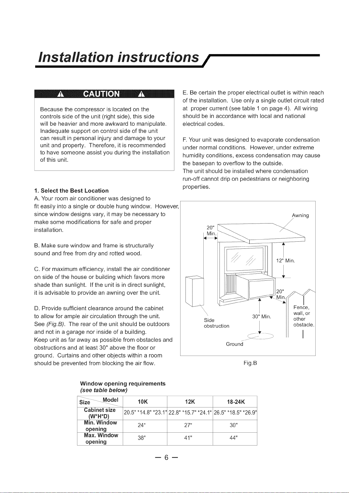
C. For maximum efficiency, install the air conditioner
on side of the house or building which favors more
shade than sunlight. If the unit is in direct sunlight,
it is advisable to provide an awning over the unit.
D. Provide sufficient clearance around the cabinet
to allow for ample air circulation through the unit.
See (Fig.B). The rear of the unit should be outdoors
and not in a garage nor inside of a building.
Keep unit as far away as possible from obstacles and
obstructions and at least 30" above the floor or
ground. Curtains and other objects within a room
should be prevented from blocking the air flow.
Window opening requirements
(see table below)
size Model=
Cabinet size
(W*H*D)
Min. Window
opening
Max. Window
opening
10K 12K 18-24K
20.5"'14.8"'23.1 22.8"'15.7"'24.1" 26.5"'18.5"'26.9"
24" 27" 30"
38" 41" 44"
\\\
Side other
obstruction v obstacle.
Ground
30"Min. wall, or
oo .........
Fig.B
Fence,
=6=
installation instructions /
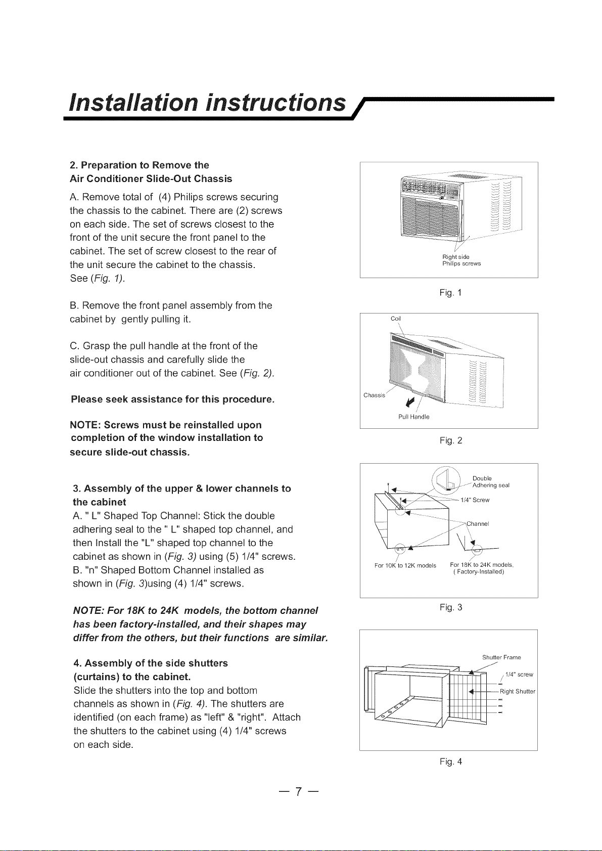
2. Preparation to Remove the
Air Conditioner Slide-Out Chassis
A. Remove total of (4) Philips screws securing
the chassis to the cabinet. There are (2) screws
on each side. The set of screws closest to the
front of the unit secure the front panel to the
cabinet. The set of screw closest to the rear of
the unit secure the cabinet to the chassis.
See (Fig. 1).
B. Remove the front panel assembly from the
cabinet by gently pulling it.
C. Grasp the pull handle at the front of the
slide-out chassis and carefully slide the
air conditioner out of the cabinet. See (Fig. 2).
Colt
Right side
Philips screws
Fig. 1
\\,
Please seek assistance for this procedure.
NOTE: Screws must be reinstalled upon
completion of the window installation to
secure slide-out chassis.
3. Assembly of the upper & lower channels to
the cabinet
A. " L" Shaped Top Channel: Stick the double
adhering seal to the " L" shaped top channel, and
then Install the "L" shaped top channel to the
cabinet as shown in (Fig. 3) using (5) 1/4" screws.
B. "n" Shaped Bottom Channel installed as
shown in (Fig. 3)using (4) 1/4" screws.
NOTE: For 18K to 24K models, the bottom channel
has been factory-installed, and their shapes may
differ from the others, but their functions are similar.
4. Assembly of the side shutters
(curtains) to the cabinet.
Slide the shutters into the top and bottom
channels as shown in (Fig. 4). The shutters are
identified (on each frame) as "left" & "right". Attach
the shutters to the cabinet using (4) 1/4" screws
on each side.
Chassis y
Pull Handle
Fig. 2
Ooubie
_- 1/4" Screw
_j .......... _ :_',Ch .... 1
For 10K to 12K models For 18K to 24K models,
(Factory-Installed)
Fig. 3
Shutter Frame
/
1/4" screw
Rrght Shutter
m7m
Fig. 4
installation instructions /
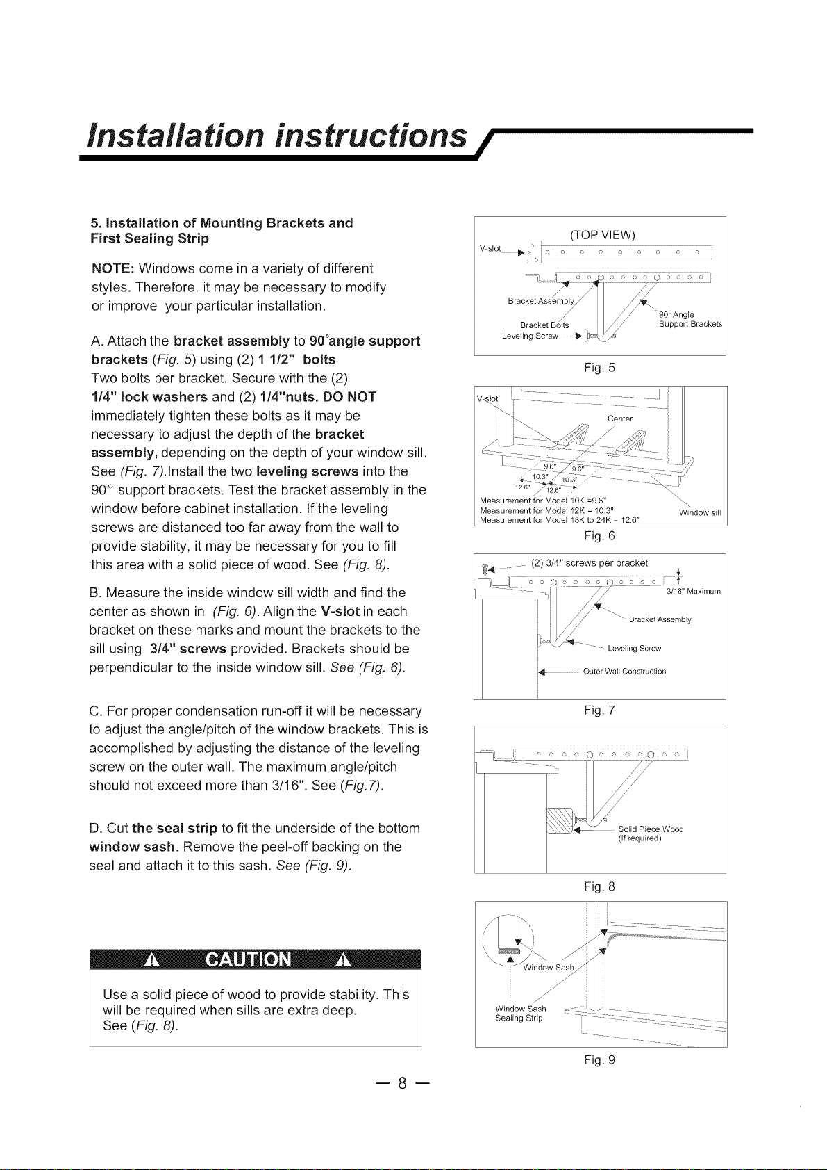
5. Installation of Mounting Brackets and
First Sealing Strip
NOTE: Windows come in a variety of different
styles. Therefore, it may be necessary to modify
or improve your particular installation.
A. Attach the bracket assembly to 90°angle support
brackets (Fig. 5) using (2) 1 1/2" bolts
Two bolts per bracket. Secure with the (2)
1/4" lock washers and (2) 1/4"nuts. DO NOT
immediately tighten these bolts as it may be
necessary to adjust the depth of the bracket
assembly, depending on the depth of your window sill.
See (Fig. 7).Enstallthe two leveling screws into the
90° support brackets. Test the bracket assembly in the
window before cabinet installation. Efthe leveling
screws are distanced too far away from the wall to
provide stability, it may be necessary for you to fill
this area with a solid piece of wood. See (Fig. 8).
B. Measure the inside window sill width and find the
center as shown in (Fig. 6). Align the V=slot in each
bracket on these marks and mount the brackets to the
sill using 3/4" screws provided. Brackets should be
perpendicular to the inside window sill. See (Fig. 6).
(TOP VIEW)
10.3"
2.6 _,, _*
Measurement for Model 10K =9.6"
Measurement for Model 12K = 10.3"
Measurement for Model 18K to 24K = 12.6"
Fig. 6
_'4............. (2) 3/4" screws _er bracket 4.
3/16" Maximum
Bracket Assembly
Leveling Screw
i_,_ ............Outer Wail Construction
\
Window sill
C. For proper condensation run-off it will be necessary
to adjust the angle/pitch of the window brackets. This is
accomplished by adjusting the distance of the leveling
screw on the outer wall. The maximum angle/pitch
should not exceed more than 3/16". See (Fig. 7).
D. Cut the seal strip to fit the underside of the bottom
window sash. Remove the peel-off backing on the
seal and attach it to this sash. See (Fig. 9).
Use a solid piece of wood to provide stability. This
will be required when sills are extra deep.
See (Fig. 8).
=8=
Window Sash
Sealing Strip
Fig. 7
(If required)
Fig. 8
Fig. 9
Installation instructions /
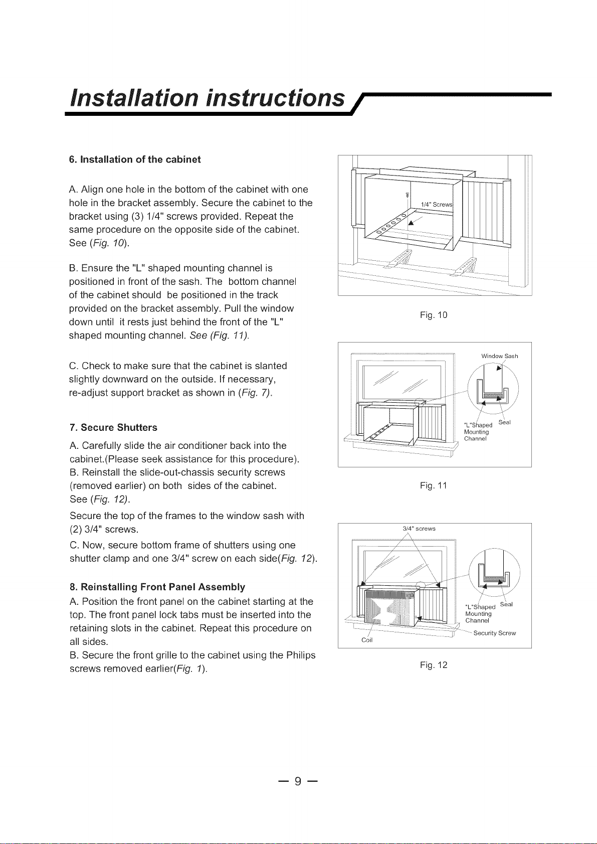
6. Installation of the cabinet
A. Align one hole in the bottom of the cabinet with one
hole in the bracket assembly. Secure the cabinet to the
bracket using (3) 1/4" screws provided. Repeat the
same procedure on the opposite side of the cabinet.
See (Fig. 10).
B. Ensure the "L" shaped mounting channel is
positioned in front of the sash. The bottom channel
of the cabinet should be positioned in the track
provided on the bracket assembly. Pull the window
down until it rests just behind the front of the "L"
shaped mounting channel. See (Fig. 11).
C. Check to make sure that the cabinet is slanted
slightly downward on the outside. If necessary,
re-adjust support bracket as shown in (Fig. 7).
Fig. 10
...................................................... Window Sash
7. Secure Shutters
A. Carefully slide the air conditioner back into the
cabinet.(Please seek assistance for this procedure).
B. Reinstall the slide-out-chassis security screws
(removed earlier) on both sides of the cabinet.
See (Fig. 12).
Secure the top of the frames to the window sash with
(2) 3/4" screws.
C. Now, secure bottom frame of shutters using one
shutter clamp and one 3/4" screw on each side(Fig. 12).
8. Reinstalling Front Panel Assembly
A. Position the front panel on the cabinet starting at the
top. The front panel lock tabs must be inserted into the
retaining slots in the cabinet. Repeat this procedure on
all sides.
B. Secure the front grille to the cabinet using the Philips
screws removed earlier(Fig. 1).
Fig. 11
3/4" screws
i
,,L,,S_I_aped Seal
Mounting
...... ,/
/ ....................... _ :y Screw
Coil
Fig. 12
Channel
=9=
Installation instructions /
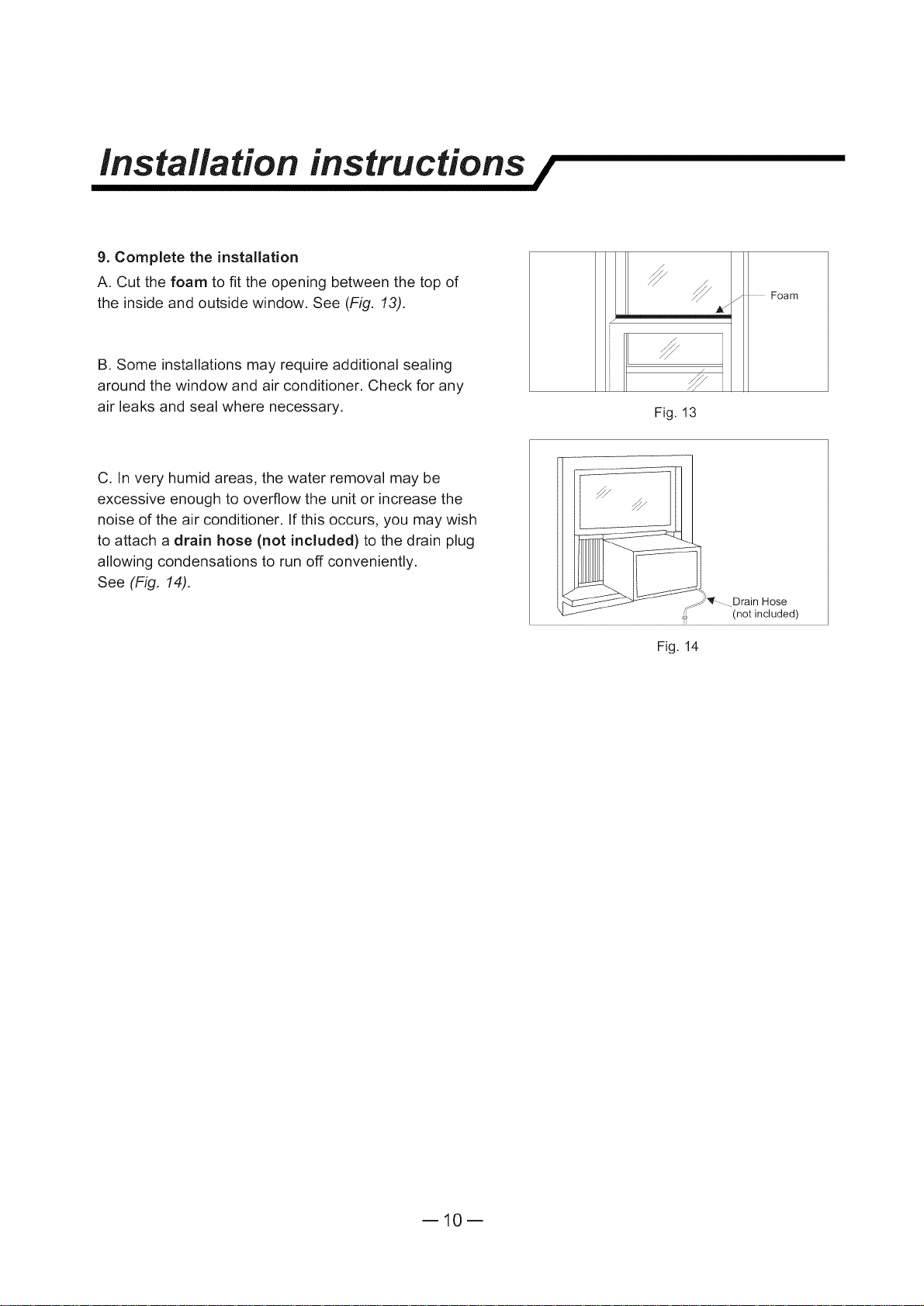
9. Complete the installation
A. Cut the foam to fit the opening between the top of
the inside and outside window. See (Fig. 13).
B. Some installations may require additional sealing
around the window and air conditioner. Check for any
air leaks and seal where necessary.
C. In very humid areas, the water removal may be
excessive enough to overflow the unit or increase the
noise of the air conditioner. If this occurs, you may wish
to attach a drain hose (not included) to the drain plug
allowing condensations to run off conveniently.
See (Fig. 14).
Foam
Fig. 13
__#'_- Drain Hose
(not included)
Fig. 14
ml0m
 Loading...