

Admiral NTW4880YQ0, NTW4600XQ0, ATW4475VQ1, NTW5100XQ0, NTW4800XQ0 Installation Instructions Manual
...Page 1
Washer Installation Instructions
Instructions pour l'installation de la laveuse
Table of Contents Table des mati_res
WASHER SAFETY ............................................................. 1 SECURITE DE LA LAVEUSE ............................................. 9
iNSTALLATiON REQUIREMENTS .................................... 2
Tools and Parts .................................................................... 2
Location Requirements ...................................................... 2
Drain System ....................................................................... 3
Electrical Requirements ..................................................... 4
INSTALLATION iNSTRUCTiONS ................................................ 4
Before you start: Remove shipping materials .................. 4
Connect Drain Hose ............................................................ 5
Connect INet Hoses ............................................................ 6
Level Washer ....................................................................... 7
COMPLETE iNSTALLATiON CHECKLIST ................................. 8
iNSTALLATiON NOTES
Date of purchase:
Date of installation:
Installer:
Model number:
Serial number:
Para obtener acceso al "lnstrucciones de installation" en espa_ol, o para obtener informaci6n adicional acerca
de su producto, visite:
www.whirlpool.com
Tenga listo su nOmero de modelo completo. Puede encontrar el ndmero de modelo y de serie dentro de la cavidad
superior de la puerta.
EXIGENCES D'INSTALLATION ......................................... 9
Outillage et pi_ces ............................................................... 9
Exigences d'emplacement ................................................ 10
Syst_me d'6vacuation ........................................................ 10
Sp6cifications 61ectriques ................................................. 11
iNSTRUCTiONS D'INSTALLATION ........................................... 12
Avant de commencer : retrait du mat6rial d'exp6dition. 13
Raccordement du tuyau de vidange ................................. 14
Raccordement des tuyaux d'ariv_e d'eau ....................... 15
(=tablissement de I'aplomb de la laveuse ......................... 15
ACHEVER L'INSTALLATION - LISTE DE VleRIFICATION ........ 16
NOTES CONCERNANT L'INSTALLATION
Date d'achat :
Date d'installation :
Installateur :
Num6ro de module :
Num6ro de s6rie :
WASHER S_ETY
Your safety and the safety of others are very important.
We have provided many important safety messages in this manual and on your appliance. Always read and obey all safety
messages.
This is the safety alert symbol.
This symbol alerts you to potential hazards that can kill or hurt you and others.
All safety messages will follow the safety alert symbol and either the word "DANGER" or "WARNING."
These words mean:
You can be killed or seriously injured if you don't immediately
follow instructions.
You can be killed or seriously injured if you don't follow
instructions.
All safety messages will tell you what the potential hazard is, tell you how to reduce the chance of injury, and tell you what can
happen if the instructions are not followed.
W10200890C
W10200891C - SP
Page 2
INSTALLATION REQU[REMENW$
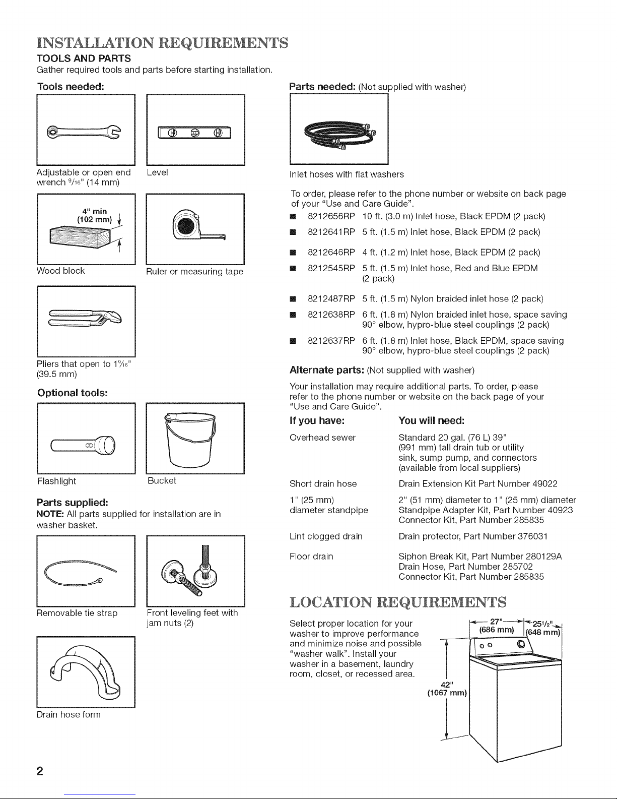
TOOLS AND PARTS
Gather required tools and parts before starting installation.
Tools needed: Parts needed: (Not supplied with washer)
m F®--®--®q
Adjustable or open end
wrench 9/16"(14 mm)
4" min
(102 mm}
Wood block
Pliers that open to 19_"
(39.5 mm)
Optional tools:
Flashlight
Level
Ruler or measuring tape
Bucket
Inlet hoses with flat washers
To order, please refer to the phone number or website on back page
of your "Use and Care Guide".
[] 8212656RP 10 ft. (3.0 m) Inlet hose, Black EPDM (2 pack)
[] 8212641RP 5 ft. (1.5 m) Net hose, Black EPDM (2 pack)
[] 8212646RP 4 ft. (1.2 m) Net hose, Black EPDM (2 pack)
[] 8212545RP 5 ft. (1.5 m) Inlet hose, Red and Blue EPDM
(2 pack)
[] 8212487RP
[] 8212638RP
[] 8212637RP
Alternate parts: (Not supplied with washer)
Your installation may require additional parts. To order, please
refer to the phone number or website on the back page of your
"Use and Care Guide".
If you have:
Overhead sewer
Short drain hose
5 ft. (1.5 m) Nylon braided inlet hose (2 pack)
6 ft. (1.8 m) Nylon braided inlet hose, space saving
90° elbow, hypro-blue steel couplings (2 pack)
6 ft. (1.8 m) Inlet hose, Black EPDM, space saving
90° elbow, hypro-blue steel couplings (2 pack)
You will need:
Standard 20 gal. (76 L) 39"
(991 mm) tall drain tub or utility
sink, sump pump, and connectors
(available from local suppliers)
Drain Extension Kit Part Number 49022
Parts supplied:
NOTE: All parts supplied for installation are in
washer basket.
Removable tie strap
Drain hose form
Front leveling feet with
jam nuts (2)
2
1" (25 mm)
diameter standpipe
Lint clogged drain
Floor drain
2" (51 mm) diameter to 1" (25 mm) diameter
Standpipe Adapter Kit, Part Number 40923
Connector Kit, Part Number 285835
Drain protector, Part Number 376031
Siphon Break Kit, Part Number 280129A
Drain Hose, Part Number 285702
Connector Kit, Part Number 285835
LOC,AT[ON REQU[REMENWS
Select proper location for your
washer to improve performance
and minimize noise and possible
"washer walk". Install your
washer in a basement, laundry
room, closet, or recessed area.
42"
(1067mm)
Page 3
You will need:
[] A water heater set to 120 ° F (49° C).
[] A grounded electrical outlet located within 4 ft. (0.9 m)
of power cord on back of washer.
[] Hot and cold water faucets located within 3 ft. (0.9 m)
of hot and cold water fill valves on washer, and water
pressure of 5-100 psi (34.5-690 kPa).
[] A level floor with maximum slope of 1" (25 mm) under entire
washer. Installing on carpet is not recommended.
[] Floor must support washer's total weight (with water
and load) of 315 Ibs (143 kgs).
IMPORTANT: Do not install, store, or operate washer where
it will be exposed to weather or in temperatures below 32° F
(0° C). Water remaining in washer after use may cause
damage in low temperatures. See "Washer Care" in your
"Use and Care Guide". Proper installation is your responsibility.
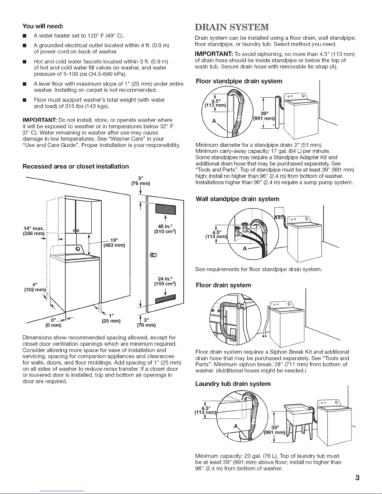
Recessed area or closet instanation
3"
[76 ram)
SYSTEM
Drain system can be installed using a floor drain, wall standpipe,
floor standpipe, or laundry tub. Select method you need.
iMPORTANT: To avoid siphoning, no more than 4.5" (113 mm)
of drain hose should be inside standpipe or below the top of
wash tub. Secure drain hose with removable tie strap (A).
Floor standpipe drain system
Minimum diameter for a standpipe drain: 2" (51 mm).
Minimum carry-away capacity: 17 gal. (64 L) per minute.
Some standpipes may require a Standpipe Adapter Kit and
additional drain hose that may be purchased separately. See
"Tools and Parts". Top of standpipe must be at least 39" (991 mm)
high; install no higher than 96" (2.4 m) from bottom of washer.
Installations higher than 96" (2.4 m) require a sump pump system.
Wall standpipe drain system
14" max. ',
1356 m , - - -
1 19"
(483 ram)
48 in.2
(31ocm_)
¢3
4"
10ram)
Dimensions show recommended spacing allowed, except for
closet door ventilation openings which are minimum required.
Consider allowing more space for ease of installation and
servicing, spacing for companion appliances and clearances
for walls, doors, and floor moldings. Add spacing of 1" (25 mm)
on all sides of washer to reduce noise transfer. If a closet door
or Iouvered door is installed, top and bottom air openings in
door are required.
(25ram}
176 ram)
24 in.2
(155cm2)
,t,,,(
(113{turn)/
See requirements for floor standpipe drain system.
Floor drain system
Floor drain system requires a Siphon Break Kit and additional
drain hose that may be purchased separately. See "Tools and
Parts". Minimum siphon break: 28" (711 mm) from bottom of
washer. (Additional hoses might be needed.)
Laundry tub drain system
\ 9 /3o,,lil rmH
Minimum capacity: 20 gal. (76 L). Top of laundry tub must
be at least 39" (991 mm) above floor; install no higher than
96" (2.4 m) from bottom of washer.
3
Page 4
ELECTRICAL REQU[REMENT$
INS LATION INSTRUC%IONS
Excessive Weight Hazard
Use two or more people to move and install washer.
Failure to do so can result in back or other injury.
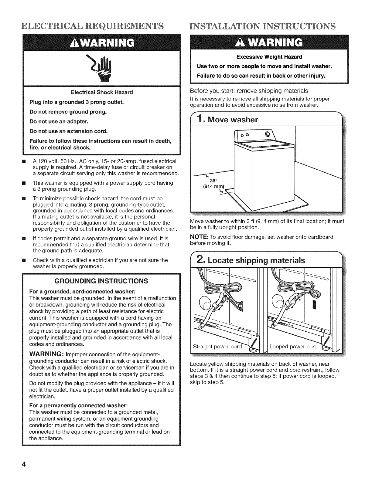
Electrical Shock Hazard
Plug into a grounded 3 prong outlet.
Do not remove ground prong.
Do not use an adapter.
Do not use an extension cord.
Failure to follow these instructions can result in death,
fire, or electrical shock.
[]
A 120 volt, 60 Hz., AC only, 15- or 20-amp, fused electrical
supply is required. A time-delay fuse or circuit breaker on
a separate circuit serving only this washer is recommended.
[]
This washer is equipped with a power supply cord having
a 3 prong grounding plug.
[]
To minimize possible shock hazard, the cord must be
plugged into a mating, 3 prong, grounding-type outlet,
grounded in accordance with local codes and ordinances.
If a mating outlet is not available, it is the personal
responsibility and obligation of the customer to have the
properly grounded outlet installed by a qualified electrician.
[]
If codes permit and a separate ground wire is used, it is
recommended that a qualified electrician determine that
the ground path is adequate.
[] Check with a qualified electrician if you are not sure the
washer is properly grounded.
Before you start: remove shipping materials
It is necessary to remove all shipping materials for proper
operation and to avoid excessive noise from washer.
1. Move washer
oo
Move washer to within 3 ft (914 mm) of its final location; it must
be in a fully upright position.
NOTE: To avoid floor damage, set washer onto cardboard
before moving it.
GROUNDING INSTRUCTIONS
For a grounded, cord=connected washer:
This washer must be grounded, in the event of a malfunction
or breakdown, grounding will reduce the risk of electrical
shock by providing a path of least resistance for electric
current. This washer is equipped with a cord having an
equipment-grounding conductor and a grounding plug. The
plug must be plugged into an appropriate outlet that is
properly installed and grounded in accordance with all local
codes and ordinances.
WARNING: Improper connection of the equipment-
grounding conductor can result in a risk of electric shock.
Check with a qualified electrician or serviceman if you are in
doubt as to whether the appliance is properly grounded.
Do not modify the plug provided with the appliance - if it will
not fit the outlet, have a proper outlet installed by a qualified
electrician.
For a permanently connected washer:
This washer must be connected to a grounded metal,
permanent wiring system, or an equipment grounding
conductor must be run with the circuit conductors and
connected to the equipment-grounding terminal or lead on
the appliance.
Locate yellow shipping materials on back of washer, near
bottom. If it is a straight power cord and cord restraint, follow
steps 3 & 4 then continue to step 6; if power cord is looped,
skip to step 5.
4
Page 5
f
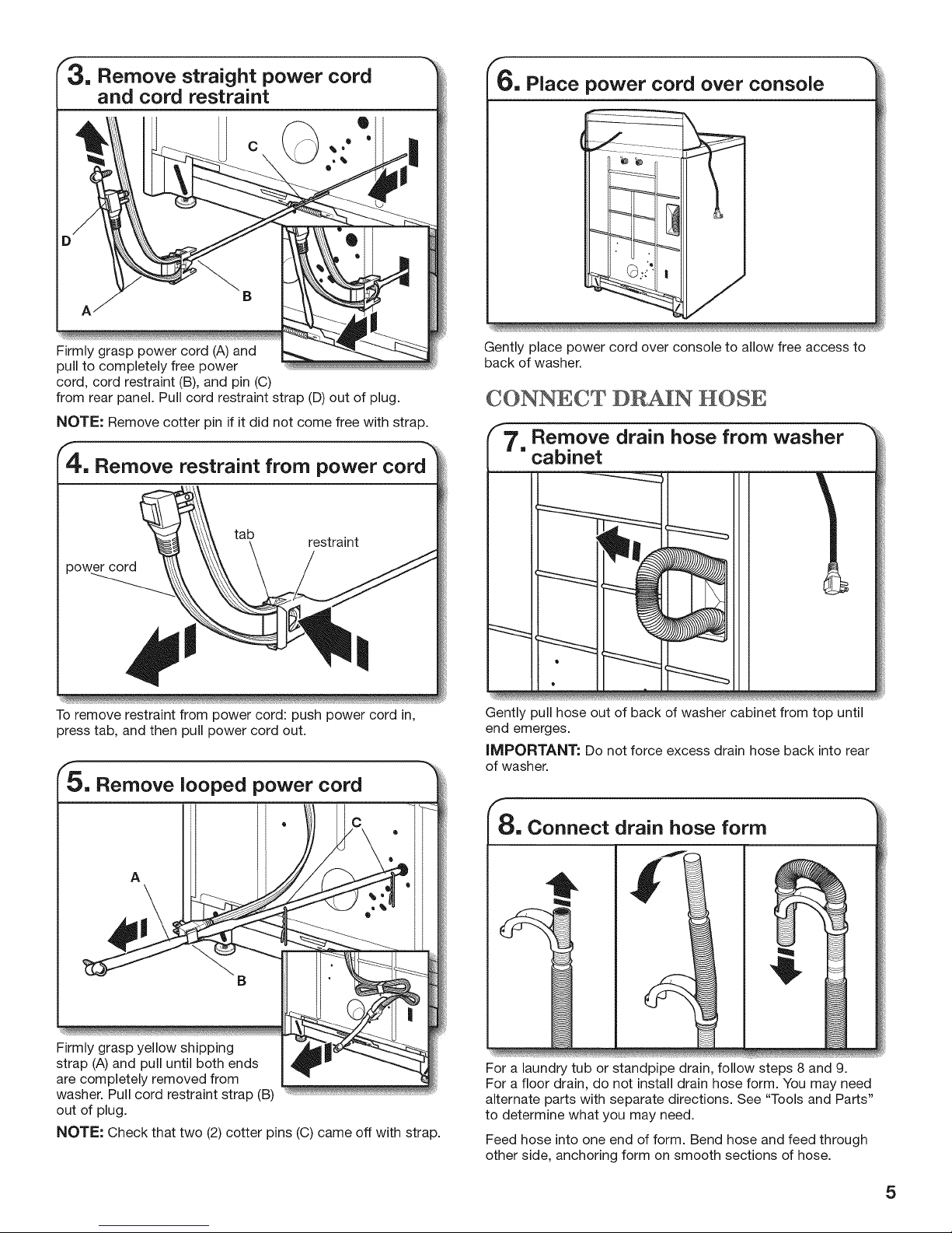
3. Remove straight power cord
and cord restraint
B
6, Place power cord over console
Firmly grasp power cord (A) and
pull to completely free power
cord, cord restraint (B), and pin (C)
from rear panel. Pull cord restraint strap (D) out of plug.
NOTE: Remove cotter pin if it did not come free with strap.
, Remove restraint from power cord
tab
power cord
%, ...... _
To remove restraint from power cord: push power cord in,
press tab, and then pull power cord out.
restraint
_, Remove looped power cord
Gently place power cord over console to allow free access to
back of washer.
CONNECT DR_N HOSE
7, Remove drain hose from washer
cabinet
Gently )ull hose out of back of washer cabinet from top until
end emerges.
iMPORTANT: Do not force excess drain hose back into rear
of washer.
A
Firmly grasp yellow shipping
strap (A) and pull until both ends
are completely removed from .......
washer. Pull cord restraint strap (B)
out of plug.
NOTE: Check that two (2) cotter pins (C) came off with strap.
8, Connect drain hose form
For a laundry tub or standpipe drain, follow steps 8 and 9.
For a floor drain, do not install drain hose form. You may need
alternate parts with separate directions. See "Tools and Parts"
to determine what you may need.
Feed hose into one end of form. Bend hose and feed through
other side, anchoring form on smooth sections of hose.
5
Page 6

Place hose into standpipe (shown in picture) or over side of
laundry tub.
iMPORTANT: No more than 4.5" (113 mm) of drain hose
should be inside standpipe; do not force excess hose into
standpipe or lay on bottom of laundry tub. Drain hose form
must be used.
CONNECT INLET HOSES
iMPORTANT: Check that your water inlet hoses have flat
washers at both ends. Washer must be connected to water
faucets with new inlet hoses with flat washers (not provided).
Do not use old hoses. Do not use hoses without washers.
1 1, Clear water lines
Run water for a few seconds through hoses into a laundry
tub, drainpipe, or bucket to prevent clogs. Water should run
until clear.
fl 2, Connect inlet hoses to washer
faucets
Attach hose to hot water faucet. Screw on coupling by hand
until it is seated on washer. Use pliers to tighten couplings an
additional two-thirds turn. Repeat this step with second hose
for cold water faucet.
iMPORTANT: Do not overtighten or use tape or sealants on
valve when attaching to faucets or washer. Damage can result.
HELPFUL TIP: Make note of which hose is connected to hot
water to help in attaching hoses to washer correctly.
Attach hot water hose to hot water inlet valve. Screw coupling
by hand until it is snug. Use pliers to tighten couplings an
additional two-thirds turn. Repeat with cold water inlet valve.
iMPORTANT: Do not overtighten or use tape or sealants on
valve when attaching to faucets or washer. Damage can result.
iMPORTANT: To reduce risk of hose failure, replace the hoses
every 5 years. Record hose installation or replacement dates for
future reference.
[] Periodically inspect and replace hoses if bulges, kinks, cuts,
wear, or leaks are found.
NOTE: Inlet valves may be arranged vertically or horizontally
depending on your model.
0
6
Turn on water faucets to check for leaks from faucet and at
washer connection. A small amount of water may enter washer.
This is normal; it will drain later.
Page 7

"14, Secure drain hose
"17. Engage rear leveling feet
Laundry Tub Standpipe
Secure drain hose to laundry tub leg, drain standpipe, or inlet
hoses for wall standpipe with removable tie strap (A). This will
help reduce the chance of drain water splashing on the floor.
Wall
LEVEL WASHER
IMPORTANT: Leveling your washer properly reduces excess
noise and vibration.
"15, Prepare to install leveling feet
©©
Tilt washer forward; self-adjusting rear feet will click into place.
Gently lower washer to floor.
"18, Check levelness of washer
oo ©
Place level here
Prop up front of washer about 4" (102 mm) with a wood block or
similar object that will support weight of washer. Then screw jam
nut onto each foot to within 1" (25 mm) of foot base.
"16, Install front leveling feet
Screw feet into threaded holes at front
corners of washer until jam nuts touch washer, but are not tight.
Tilt washer back, remove wood block. Gently lower washer to
floor and slide washer to its final location. Remove cardboard
used to protect floor.
Place a level on top edges of washer, checking each side
and front. Rock washer back and forth to make sure all four
feet make solid contact with floor. If not level, tip washer and
adjust feet up or down, repeating as necessary.
Not Level LEVEL Not Level
7
Page 8

f
1 9, Tighten leveling feet
A
When washer is level, hold the leveling foot to keep it from
turning and use a 9/16" or 14 mm open-end or adjustable
wrench to tighten jam nut (A) counterclockwise on foot
securely against washer cabinet.
HELPFUL TiP: You may want to prop washer again with
wooden block, then make sure to recheck for levelness.
COMFLEWE INS%ALLAWION
CHECKLIST
[]
Check electrical requirements. Be sure you have correct
electrical supply and recommended grounding method.
m
Check that all parts are now installed. If there is an extra
part, go back through steps to see what was skipped.
m
Check that you have all of your tools.
m
Check that yellow shipping materials were completely
removed from back of washer.
Check that both water faucets are on.
[]
[]
Check for leaks around faucets and inlet hoses.
[]
Remove film from console and any tape remaining
on washer.
[]
Check that washer is plugged into a grounded
3 prong outlet.
[]
Dispose of/recycle all packaging materials.
[]
Read "Washer Use" in your "Use and Care Guide".
[]
Totest and clean your washer, measure 1/2 of normal
recommended amount of powdered or liquid detergent
and pour it into washer basket or detergent dispenser
(on some models). Close lid. Select any cycle. Start washer
and allow to complete full cycle.
Electrical Shock Hazard
Plug into a grounded 3 prong outlet.
Do not remove ground prong.
Do not use an adapter.
Do not use an extension cord.
Failure to follow these instructions can result in death,
fire, or electrical shock.
20, Plug into a grounded
3 prong outlet
8
Page 9

p p
$NCURXTN DE LA LA_USN
Votre s_curit_ et celle des autres est tr_s importante.
Nous donnons de nombreux messages de securit6 importants dans ce manuel et sur votre appareil m6nager. Assurez-vous de
toujours lire tous les messages de securit6 et de vous y conformer.
Voici le symbole d'alerte de s6curit&
Ce symbole d'alerte de s6curit6 vous signale les dangers potentiels de d6c_s et de blessures graves & vous
et & d'autres.
Tousles messages de s_curit6 suivront le symbole d'alerte de securit6 et le mot "DANGER" ou
"AVERTISSEMENT". Ces mots signifient :
Risque possible de d_c_s ou de blessure grave si vous ne
suivez pas imm_diatement les instructions,
Risque possible de d_c_s ou de blessure grave si vous
ne suivez pas les instructions.
Tous les messages de securit6 vous diront quel est le danger potentiel et vous disent comment r6duire le risque de blessure et
ce qui peut se produire en cas de non-respect des instructions.
EXXGENCNS D'XN$ LATXON
OUTILLAGE ET PIECES
Rassembler les outils et pieces n6cessaires avant de
commencer I'installation.
Outillage n_cessaire :
Pi_ces fournies :
REMARQUE : Toutes les pieces fournies pour
I'installation se trouvent darts le panier de la laveuse.
@
CI6 plate ou r6glable Niveau
de 9/16"(14 mm)
4"" rain
(102 ram))
Cale en bois
Pince avec ouverture jusqu'&
19/16'' (39,5 mm)
Outillage facultatif :
Regle ou metre ruban
Attache de fixation
amovible
Bride de retenue pour
tuyau de vidange
Pi_ces n_cessaires
Tuyaux d'arriv6e d'eau
avec rondelles plates
Pieds de nivellement avant
avec contre-6crous (2)
(Non fournies avec la laveuse)
Lampe de poche Seau
9
Page 10

Pour commander, consulter les num@os d'appel sans frais
figurant sur la couverture arriere des Instructions d'utilisation
de la laveuse.
[] 8212656RP Tuyau d'arriv6e d'eau de 10 pi (3 m),
EPDMnoirs (lot de 2)
[] 8212641RP Tuyau d'arriv6e d'eau de 5 pi (1,5 m), EPDM
noirs (lot de 2)
[] 8212646RP Tuyau d'arriv6e d'eau de 4 pi (1,2 m), EPDM
noirs (lot de 2)
[] 8212545RP Tuyau d'arriv6e d'eau de 5 pi (1,5 m), EPDM
rouge et bleu (lot de 2)
[] 8212487RP Tuyau d'arriv6e en nylon tress6 de 5 pi (1,5 m)
(lot de 2)
[] 8212638RP Tuyau d'arriv6e en nylon tress6 de 6 pi (1,8 m),
coude compact de 90°, raccords hypro-blue
en acier (lot de 2)
[] 8212637RP
Tuyau d'arriv6e de 6 pi (1,8 m), EPDM noir,
coude compact de 90°, raccords hypro-blue
en acier (lot de 2)
Autres pi_ces : (Non fournies avec la laveuse)
IIse peut que I'installation n6cessite des pieces suppl6mentaires.
Pour commander, consulter les num@os d'appel sans frais
figurant sur la couverture arriere des Instructions d'utilisation
de la laveuse.
SJ vous avez :
Un egout surelev6
II vous faudra :
Tuyau de vidange standard de 20 gal.
(76 L) de 39" (991 mm) de haut ou
evier de decharge, pompe de puisard
et connecteurs (disponibles chez les
vendeurs de mat@iel de plomberie
Iocaux)
Un tuyau de vidange
trop court
Un tuyau rigide de rejet
I'egout de 1" (25 mm)
de diametre
Ensemble de raccord de tuyau
d'evacuation - N° de piece 49022
Un ensemble d'adaptateur de 2" (51ram)
1" (25mm) de diametre pour letuyau
rigide de rejet a I'egout, N° de piece 40923
Ensemble de raccord, N° de piece 285835
Le systeme d'evacuation
obstrue par de la charpie
Un tuyau d'evacuation
au plancher
Protecteur de canalisation,
N° de piece 376031
Ensemble de brise-siphon,
N° de piece 280129A
Tuyau d'evacuation, N° de piece 285702
Ensemble de raccord, N° de piece 285835
EXIGENCES D'EMPLACEMENT
Le choix d'un emplacement
appropri6 pour la laveuse
en am61iore le rendement
et r6duit au minimum
le bruit et le "d6placement"
possible de la laveuse. La
laveuse peut _tre install6e
dans un sous-sol, une salle
de buanderie, un placard
ou un encastrement.
42"
(1067ram)
II vous faudra :
[]
Un chauffe-eau r6g16& 120° F (49° C).
[]
Une prise 61ectrique reli6e & la terre et situ6e &moins
de 4 pi (0,9 m) du cordon d'alimentation situ6 & I'arriere
de la laveuse.
[]
Des robinets d'eau chaude et d'eau froide situ6s a moins
de 3 pi (0,9 m) des 61ectrovannes de remplissage d'eau
chaude et d'eau froide situ6es sur la laveuse et une
pression d'eau de 5-100 Ib/po 2(34,5 a 690 kPa).
[]
Un plancher de niveau avec une pente maximale
de 1" (25 mm) sous I'ensemble de la laveuse. Uinstallation
sur de la moquette n'est pas recommand6e.
[]
Un plancher capable de supporter le poids total
de 315 Ib (143 kg) de la laveuse (eau et charge compris).
iMPORTANT : Ne pas installer, remiser ou faire fonctionner la
laveuse & un emplacement oQelle sera expos6e aux intemp6ries
ou & des temp6ratures inf6rieures & 32° F (0° C). De I'eau rest6e
dans la laveuse apres utilisation peut causer des dommages
&basse temp6rature. Voir "Entretien de la laveuse" dans les
Instructions d'utilisation de la laveuse pour des renseignements
sur I'hiv6risation.
C'est &I'utilisateur qu'incombe la responsabilit6 de r6aliser une
installation correcte.
installation darts un encastrement ou un placard
3 ml
(76 mm)
.q=2]
14" max. ', I
(356mm) .... "---
/ 19"
(463 mm)
48 in. _
(310 cm 2)
¢3
24 in. _
(155cm2)
J
k,,,
(6 ram)
(25mm)
Les dimensions repr6sentent les d6gagements recommand6s
permis, hormis pour les ouvertures de ventilation de la porte
du placard qui correspondent aux dimensions minimales
n6cessaires. On peut 6ventuellement laisser davantage
de d6gagement pour faciliter I'installation et I'entretien,
des distances de s6paration pour les appareils m6nagers
voisins et des d6gagements pour les murs, portes et plinthes.
Ajouter un espace suppl6mentaire de 1" (25 mm) de tousles
c6t6s de la laveuse pour r6duire le transfert de bruit. Si I'on
installe une porte de placard ou une porte a persiennes, des
ouvertures d'a@ation au sommet et au bas de la porte sont
n6cessaires.
f3"
(76ram)
10
Page 11

SYS%EME DE VID GN
Le systeme de vidange de la laveuse peut 6tre install6
& I'aide d'un conduit d'6vacuation au plancher, un tuyau
de rejet a 1'6gout au plancher ou mural ou un 6vier
de buanderie. S61ectionner la m6thode a utiliser.
IMPORTANT." Pour 6viter un effet de siphon, ne pas
introduire plus de 4.5" (113 ram) de tuyau de vidange
& I'int@ieur du tuyau de rejet & 1'6gout ou sous la partie
sup@ieure de la cuve de lavage. Immobiliser le tuyau
de vidange avec I'attache de fixation amovible (A).
Syst_me de vidange avec tuyau de rejet _ 1'6gout
au plancher
Diametre minimal pour un tuyau de rejet & 1'6gout : 2" (51 mm).
Capacit6 minimale d'acheminement : 17 gal. (64 L) par minute.
Certains tuyaux rigides de rejet a 1'6gout peuvent n6cessiter
un ensemble d'adaptateur pour tuyau rigide de rejet & 1'6gout
et un tuyau d'6vacuation suppl6mentaire qui peuvent 6tre
achet6s s@ar6ment. Voir "Outillage et pieces". Le sommet
du tuyau de rejet & 1'6gout dolt avoir une hauteur d'au moins
39" (991 mm); ne pas I'installer & plus de 96" (2,4 m) du fond
de la laveuse. Si on dolt I'installer & plus de 96" (2,4 m)
de hauteur, un systeme de pompe de puisard est n6cessaire.
Syst_me de vidange avec tuyau de rejet
1'6gout mural
Syst_me de vidange dans un 6vier de buanderie
Capacit6 minimale : 20 gal. (76 L). Le sommet de 1'6vier de
buanderie dolt se trouver & au moins 39" (991 mm) du plancher;
ne pas I'installer & plus de 96" (2,4 m) du fond de la laveuse.
SPNCIFIC,ATION$ NLECTAIQUES
Risque de choc 61ectrique
Brancher sur une prise/_ 3 alv6oles reli6e a la terre.
Ne pas enlever la broche de liaison & la terre.
Ne pas utiliser un adaptateur.
Ne pas utiliser un c_ble de rallonge.
Le non=respect de ces instructions peut causer
un d6c_s, un incendie ou un choc 61ectrique.
Voir les exigences pour le systeme de vidange avec tuyau
de rejet & 1'6gout au plancher.
Syst_me de vidange au plancher
Le systeme de vidange au plancher n6cessite un ensemble
de brise-siphon et un tuyau de vidange suppl6mentaire qui
peuvent 6tre achet6s s@ar6ment. Voir "Outillage et pieces".
Dimension minimale pour le brise-siphon : 28" (711 mm)
&partir du fond de la laveuse. (Des tuyaux suppl6mentaires
peuvent 6tre requis).
Une alimentation de 120 volts, 60 Hz, CA seulement,
de 15 ou 20 amperes, prot6g6e par un fusible est requise.
Une alimentation de 120 volts, 60 Hz, CA seulement,
de 15 ou 20 amp@es, prot6g6e par un fusible est requise.
On recommande I'emploi d'un fusible ou d'un disjoncteur
temporis& II est recommand6 de raccorder la laveuse
sur un circuit distinct exclusif & cette laveuse.
[]
Cette laveuse comporte un cordon d'alimentation
61ectrique & trois broches pour liaison & la terre.
[]
Pour minimiser les risques de choc 61ectrique, on
dolt brancher le cordon sur une prise de courant de
configuration correspondante, b,3 alv6oles, reli6e b, laterre
et install6e conform6ment aux codes et reglements Iocaux.
Si une prise de courant de configuration correspondante
n'est pas disponible, le client a la responsabilit6 et
I'obligation de faire installer par un 61ectricien qualifi6 une
prise de courant correctement reli6e &la terre.
Si les codes le permettent et si I'on utilise un conducteur
distinct de liaison & la terre, il est recommand6 qu'un
61ectricien qualifi6 v&ifie la qualit6 de la liaison & la terre.
En cas de doute quant b,la qualit6 de la liaison & la terre
de la laveuse, consulter un 61ectricien qualifi&
11
Page 12

iNSTRUCTiONS DE LiAiSON A LA TEl:IRE
Pour une laveuse reli_e _ la terre et connect_e par
un cordon :
Cette laveuse dolt 6tre reli6e &la terre. En cas d'anomalie
de fonctionnement ou de panne, la liaison &la terre r6duira
le risque de choc 61ectrique en offrant au courant 61ectrique
un itin6raire d'6vacuation de moindre r6sistance. Cette
laveuse est aliment6e par un cordon electrique comportant
un conducteur reli6 & la terre et une fiche de branchement
munie d'une broche de liaison & la terre. La fiche doit 6tre
branch6e sur une prise de courant appropri6e qui est bien
install6e et reli6e & Jaterre conform6ment & tous Jes codes
et reglements Iocaux.
AVERTISSEMENT : Le raccordement incorrect de cet
appareiJ au conducteur de liaison & Jaterre peut susciter un
risque de choc eJectrique. En cas de doute quant & la qualit6
de la liaison & la terre de I'appareil, consulter un eJectricien
ou technicien d'entretien qualifi&
Ne pas modifier la fiche de branchement fournie avec
J'appareil - si la fiche ne correspond pas & la configuration
de Ja prise de courant, demander & un 6Jectricien quaJifi6
d'instaJler une prise de courant convenable.
Pour une laveuse raccord_e en permanence :
Cette laveuse dolt 6tre raccord6e & un syst_me de c&blage
permanent en m6tal reli6 & la terre ou un conducteur reli6 &
la terre doit 6tre en fonction avec les conducteurs de circuit
et raccord6s & la borne de liaison & la terre ou la borne sur
I'appareil m6nager.
REMARQUE : Pour 6viter d'endommager le plancher, installer
la laveuse sur un carton avant de la d6placer.
Rep@er I'emplacement du mat@iel d'exp6dition jaune situe
&I'arriere de la laveuse, pros du fond. S'il s'agit d'un cordon
d'alimentation droit et d'un dispositif d'immobilisation du cordon
d'alimentation, suivre les 6tapes 3 et 4, puis passer & 1'6tape 6; s'il
s'agit d'un cordon d'alimentation en boucle, passer a 1'6tape 5.
Oter le cordon d'alimentation droit
et le dispositif d'immobilisation du
cordon d'alimentation.
INSTRUCTIONS D'INS LAT[ON
Risque du poids excessif
Utiliser deux ou plus de personnes pour d_placer et
installer la laveuse.
Le non=respect de cette instruction peut causer une
blessure au dos ou d'autre blessure.
Avant de commencer : retirer le mat6riel d'exp6dition
II est necessaire de retirer tout le mat@iel d'exp6dition pour un
fonctionnement correct et pour 6viter que la laveuse ne fasse
trop de bruit.
"1, D_placer ia laveuse
oo ©
Saisir fermement le cordon
d'alimentation (A) et tirer pour le d6gager
completement ainsi que le dispositif
d'immobilisation (B) et la broche (C) du panneau arriere.
Oter I'attache de retenue du cordon d'alimentation (D)
hors de la prise.
REMARQUE : Oter la goupille si elle n'a pas 6t6 d6gag6e en
m_me temps que I'attache.
D6placer la laveuse a moins de 3 pi (914 mm) de son
emplacement final, elle dolt _tre en position completement
verticale.
12
Page 13

4, Retirer i'attache du cordon
d'alimentation
onglet
attache
cordon
d'alimentation
Pour retirer I'attache du cordon d'alimentation " enfoncer
le cordon d'alimentation, appuyer sur I'onglet, puis extraire
le cordon d'alimentation.
5, Retirer le cordon d'alimentation
en boucle
_CCORDNMENT DU TUYAU
DE ¥_D,_GE
Lib_rer le tuyau de vidange de la
caisse de ia iaveuse
Extraire d61icatement le tuyau de I'arri_re de la caisse de la
laveuse a partir du sommet jusqu'a ce que le bout apparaisse.
IMPORTANT : Ne pas forcer I'exc6dent du tuyau de vidange
dans I'arriere de la laveuse.
8, Raccorder la bride de retenue pour
tuyau de vidange
A
B
Saisir fermement la sangle
d'exp6dition jaune (A) et tirer
jusqu'a ce que les deux
extr6mit6s soient completement
d6gag6es de la laveuse. Oter I'attache de retenue
du cordon d'alimentation (B) hors de la prise.
REMARQUE : V6rifier que deux (2) goupilles ont 6t6
retir6es (C)avec la sangle.
Placer ie cordon d'alimentation par
dessus la console
Pour un 6vier de buanderie ou un tuyau de rejet a 1'6gout, suivre
les 6tapes 8 et 9. Pour un conduit d'6vacuation au plancher, ne
pas installer de bride de retenue pour tuyau de vidange. Des
pieces suppl6mentaires avec des directives distinctes seront
peut-_tre n6cessaires. Voir "Outillage et pieces".
Ins6rer le tuyau dans I'une des extr6mit6s de la bride de retenue,
plier le tuyau et continuer d'ins6rer le tuyau jusqu'a I'autre c6t6
tout en fixant la bride de retenue aux sections lisses du tuyau.
Placer d61icatement le cordon d'alimentation par dessus la
console pour permettre le libre acc_s a I'arriere de la laveuse.
13
Page 14

Placer le tuyau dans le tuyau de rejet a 1'6gout (illustr6 sur
I'image) ou par-dessus le c6t6 de 1'6vier de buanderie.
IMPORTANT : IIne dolt pas y avoir plus de 4,5" (113 mm) de
tuyau de vidange a I'int@ieur du tuyau de rejet a 1'6gout; ne pas
forcer I'exc6dent de tuyau dans le tuyau de rejet a 1'6gout ni
le placer dans 1'6vier de buanderie. On doit utiliser la bride de
retenue pour tuyau de vidange.
_CCORDEMENT DES T X
D_ARRI¥_E D_EAU
1 "1, Purger les canalisations d'eau
Faire couler I'eau par les tuyaux dans 1'6vier de buanderie, le
tuyau de rejet a 1'6gout ou le seau pendant quelques secondes
pour 6viter toute obstruction. On dolt laisser couler I'eau jusqu'&
ce qu'efle soit limpide.
fl 2, Raccorder les tuyaux d'arriv_e
d'eau a la laveuse.
IMPORTANT : V@ifier que les tuyaux d'arriv6e d'eau ont
les rondelles plates aux deux extr6mit6s. La laveuse dolt _tre
raccord6e aux robinets d'eau a I'aide des nouveaux tuyaux
d'arriv6e d'eau avec les rondelles plates (non fournis). Ne
pas utiliser de tuyaux usag6s. Ne pas utiliser de tuyaux sans
rondelles.
Raccorder les tuyaux d'arriv6e
d'eau aux robinets
Fixer le tuyau au robinet d'eau chaude. Visser le raccord & la
main pour qu'il repose sur la rondelle. Serrer les raccords de
deux tiers de tour suppl6mentaires a I'aide d'une pince. R6p6ter
cette 6tape avec le deuxieme tuyau pour le robinet d'eau froide.
IMPORTANT : Ne pas serrer excessivement ni utiliser de
ruban adh6sif ou de dispositif d'6tanch6Jt6 sur la valve lots
de la fixation aux robinets ou a la laveuse. Cela pourrait
entraTner des dommages.
Fixer le tuyau d'eau chaude au robinet d'arriv6e d'eau chaude.
Visser le raccord a la main jusqu'a ce qu'il soit bien serr& Serrer
les raccords de deux tiers de tour suppl6mentaires a I'aide d'une
pince. R6p6ter pour le robinet d'eau froide.
IMPORTANT : Ne pas serrer excessivement ni utiliser de
ruban adh_sif ou de dispositif d'6tanch6it6 sur la valve lots de la
fixation aux robinets ou a la laveuse. Cela pourrait entraTner des
dommages.
IMPORTANT : Pour r6duire le risque de d6faillance des tuyaux,
remplacer les tuyaux tousles 5 ans. Inscrire la date d'installation
ou de remplacement des tuyaux pour r6f@ence ult@ieure.
Ill Inspecter p6riodiquement les tuyaux et les remplacer
en cas de renflement, de d6formation, de coupure, d'usure
ou sJune fuite se manifeste.
REMAROUE : Les robinets d'arriv6e d'eau peuvent _tre install6s
verticalement ou horizontalement selon le modele.
CONSEIL UTILE : Rep@er quel tuyau est raccord6 & I'eau
chaude pour permettre une fixation correcte des tuyaux
& la laveuse.
14
Ouvrir les robinets d'eau pour v@ifier qu'il n'y a pas de fuite.
Une petite quantit6 d'eau peut entrer dans la laveuse. C'est
normal. Elle s'6vacuera plus tard.
Page 15

Tuyauderejet&
1'6gout
Mur
1 7, Engager les pieds de
=_
arrlere
geaupie( erie,
autuyauderejeta1'6goutouauxtuyauxd'arriv6ed'eaupour
letuyauderejeta1'6goutmuralavecI'attachedefixation
amovible(A).Ceciaideraar6duirelapossibilit6deI'eaude
vidange6claboussantsurleplancher.
LISSEMENT DE L'APLOr_B
DE LA L USE
IMPORTANT : L'6tablissement correct de I'aplomb de la
laveuse permet de r6duire les nuisances sonores et de limiter
les vibrations.
5, Pr6parer i'instailation des pieds _
de nivellement
K
m
Faire basculer la laveuse vers I'avant; les pieds auto-r6glables
arriere s'embofteront. Abaisser d61icatement la laveuse pour la
faire reposer sur le sol.
1 8, Contr61er i'aplomb de ia iaveuse
oo Q
placer le niveau
&cet endroit
Placer un niveau sur les bords sup6rieurs de la laveuse en
contr61ant chaque c6t6 et I'avant. Faire bouger la laveuse
d'avant en arriere pour s'assurer que les quatre pieds sont
bien en contact avec le plancher. Si elle n'est pas d'aplomb,
faire basculer la laveuse et r6gler les pieds vers le haut ou
vers le bas puis recommencer si n6cessaire.
Soulever I'avant de la laveuse d'environ 4" (102 mm) a I'aide
d'une cale en bois ou d'un objet similaire qui soutiendra le poids
de la laveuse. Visser ensuite le contre-6crou sur chaque pied
jusqu'a moins de 1" (25 mm) de la base du pied.
"1 6, Installer les pieds de nivellement
avant
Visser les pieds dans les trous filet6s aux
angles avant de la laveuse, jusqu'a ce clue les contre-6crous
soient en contact avec la laveuse mais sans _tre serr6s. Faire
basculer la laveuse vers I'arriere, retirer la cale en bois. Abaisser
d61icatement la laveuse pour la faire reposer sur le sol puis
la faire glisser jusqu'& son emplacement final. Oter le morceau
de carton utilis6 pour prot6ger le plancher.
Pas d'aplomb APLOMB Pas d'aplomb
15
Page 16

f
1 9, Serrer les pieds de nivellernent
Lorsque la laveuse est d'aplomb, tenir le pied de nivellement
pour empecher le pied de tourner, et utiliser une cl6 r6glable
ou plate de 9/16" ou de 14 mm pour serrer dans le sens
antihoraire le contre-6crou (A) du pied solidement contre la
caisse de la laveuse.
CONSEIL UTILE : On devra peut-_tre de nouveau relever la
laveuse a I'aide d'une cale de bois, puis v6rifier de nouveau le
bon aplomb de la laveuse.
LISTS DE ¥_RIFICATION
POUR UACHE_MENT
DE UINS%ALLATION
[]
Consulter les sp6cifications 61ectriques. S'assurer de disposer
d'une source d'61ectricit6 appropri6e et d'une liaison a la terre
conforme a la m6thode recommand6e.
[]
V6rifier que toutes les pieces sont maintenant install6es. S'il
reste une piece, passer en revue les diff6rentes 6tapes pour
d6couvrir laquelle aurait 6t6 oubli6e.
[]
V6rifier la pr6sence de tousles outils.
[]
V6rifier que tout le mat6riel d'exp6dition jaune a 6t6 retir6 de
I'arriere de la laveuse.
[]
V6rifier que touts les deux robinets d'eau sont ouverts.
[]
V6rifier qu'il n'y a pas de fuite autour des robinets et des
tuyaux d'arriv6e d'eau.
[]
Oter la pellicule de la console et tout ruban adh6sif rest6 sur
la laveuse.
[]
V6rifier que la laveuse est branch6e sur une prise de courant
3 alv6oles reli6e a la terre.
[]
#liminer/recycler tousles mat6riaux d'emballage.
[]
Life "Utilisation de la laveuse" dans les Instructions
d'installation de la laveuse.
[]
Pour tester et nettoyer la laveuse, mesurer la moiti6 de la
quantit6 normale recommand6e de d6tergent en poudre
ou liquide et la verser dans le panier de la laveuse ou le
distributeur de d6tergent (sur certains modeles). Fermer le
couvercle. S61ectionner n'importe quel programme. Mettre
la laveuse en marche et la laisser ex6cuter un programme
complet.
Risque de choc _lectrique
Brancher sur une prise & 3 alv_oles reli_e _ la terre.
Ne pas enlever la broche de liaison & la terre.
Ne pas utiliser un adaptateur.
Ne pas utiliser un c&ble de rallonge.
Le non=respect de ces instructions peut causer
un d_c_s, un incendie ou un choc _lectrique.
r
20, Brancher sur une prise
_ 3 alv6oles reli6e a la terre.
W102008900
W102008910 = SP
02010
All rights reserved
Tous droits r6serv6s.
16
08/1 0
Printed in U.S.A.
Imprim6 aux #.-U.
 Loading...