

Admiral C322C2, CS322C2, C322C17, CS322C17, CS322C26 Service Manual
...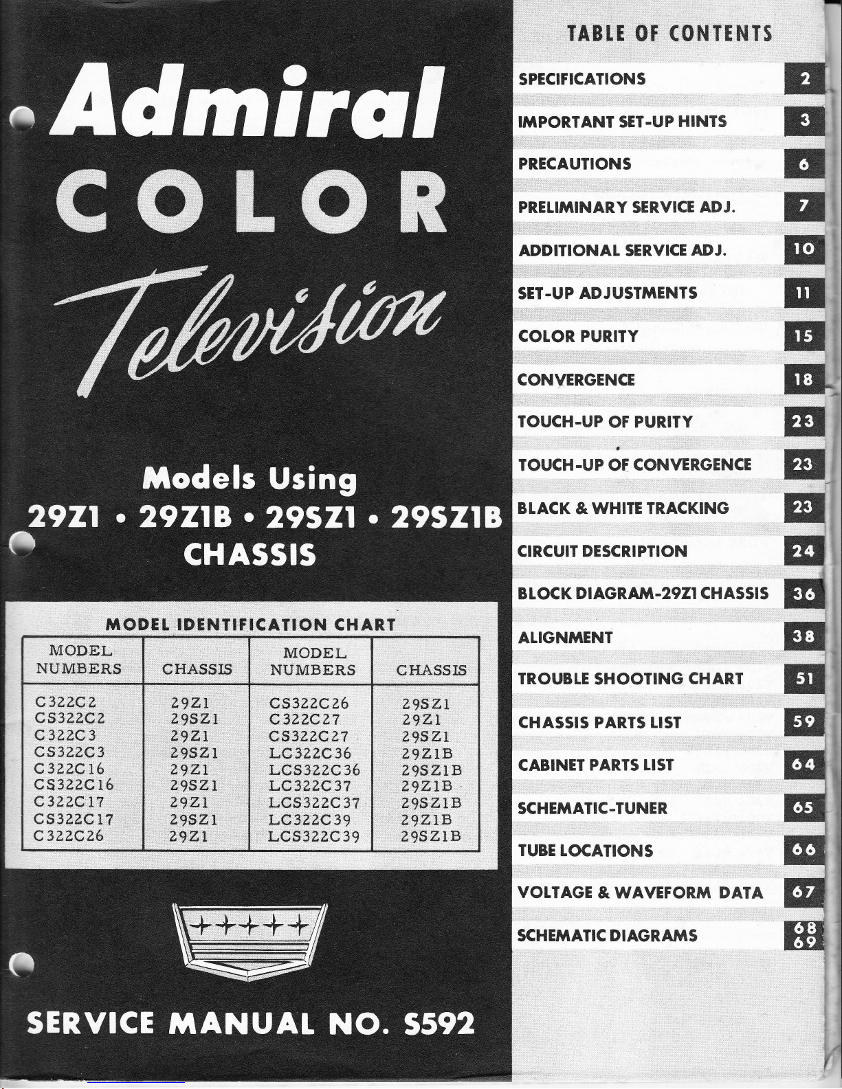
TODTL IDTNTITICAIION
CHART
MODEL
NUMBERS
CHASSI5
MODEL
NUMBERS
CHASSIS
C3ZZCz
CS3?,ZCZ
C3Z?,C3
cs3z.z.c3
C3Z?,Q16
cs322C
l6
C3ZZCTT
CSSZ?,C11
c3?.zcz6
29ZI
EgSZI
29z;,1
ZgSZI
ZgZL
Z9SZI
ZgZL
Z9SZL
Z9.ZL
QS3?,ZCZ6
C32ZCZ7
cs3zzc?7
LC3?2C36
LCs3ezc
35
LC3ZZ,C37
LCS322C37
LC3ZZC39
LQ,3ZZC39
Z9SZI
zgzr
ZgSZL
Z,9ZIB
ugszlB
ZgZLB
LgSZLB
?9ZIB
z95ZlB
TABII OT
(ONTTNTS
SPECIFICATIONS
IIITPORTANT SET.UP
HINTS
PRECAUTIONS
PRELIMINARY SER,VICE ADJ.
ADDITIONAT SERVICE
ADJ.
SET.UP
ADJUST'IIENTS
COLOR PURITY
CONVERGENCE
TOUCH.UP
OF
PURITY
TOUCH.UP OF
CONVERGENCE
BTACK
& WHITE
TRACKING
CIRCUIT DESCRIPTION
B L
OC
K
D I
AGRAIVI
.2921
CH ASSI
S
ALIGNTYTENT
TROUBLE
SHOOTING
CHAR,T
CHASSIS PARTS
LIST
CABINET
PAR.TS LIST
SCHEMATIC-TUNER
TUBE
LOCATIONS
VOLTAGE
&
WAVEFOR.frT DATA
SCHEfrTATIC DIAGRA}TS
E"
rr
rt
n,
E
r
E'
B
E
E
Iil
w
I
E
Etr
EI
E
,t
E'
ql
q1
@l
:;
BI
Pege
2
SPECIFICATIONS
PICTURE
TUBE
Type
2LAXPZZA
round
21't
three
gun
shadow
rnask type--alurninized tricolor
phosphor
screen.
Magnetic
deflection--rnagnetic
convergence--electrostatic
focus.
OPERATING VOLTAGE
110-120
volts, 60 cycles,
AC only
WATTAGE
380
watts
INPUT IMPEDANCE
300
ohrns balanced
to
ground.
ANTENNA
See
TIANTENNA
REQUIREMENTSTT on
page
4.
IF
T'REQUENCIES
Intercarrier
IF: Video
45.75
MCi
Sound. 4L.25
MC
Sound
IF:
4.5
MC
FUSE
LOCATION
See
rrTube"Location
Diagrarn'r
on
page 56.
IUBE
COiTPLEMENT
2921
vI0l
Y102
v20l
YZO2
YZo3
YZ04
vzoS
YZ06
v301
v302
v303
v401
Y402
v403
Y404
6BN4
VHf'RF
Arnp.
6CG8
VHF
Mixer-Osc.
6AZ6 tst
IF Arnplifier
5826 2nd
IF Amplifier
6826
3rd
IF Amplifier
6CB5 4th
IF Arnplifier
LZBYT
Luminance
(Y)
Arnplilier
6au6
Gated AGC
5UB
Sound IF.
-
lst Audio Arnp.
6AL5 Ratio Detector
6V6cT
Audio
Output
6AW8 lst
Chrorna
Arnp.
-Color
Killer
5CL6
Chrorna
Amplifier
LZB}IT
Chrorna
Demodulator
?LAXPZZA
Picture Tube
V501
5BH8
Burst Amp.
-Pulse
Shaper
V502
6AL5 Color
Phase
Discrirninator
V503
6U8 3.58
MC
Osc. - Osc.
Control
V601
6CS6 Sync
Separator
V602
6CG7 Sync
Inv. - Vert. Osc.
V603
6AQ5
Vertical Output
V604
6CGZ
Horizontal
Oscillator
V605
5CB5A Horizontal Output
v606
6AU4caA Damper
Y607
IYZ Focus Rectifier
V608
3A3
H. V.
Rectifier
V609
6BK4 Shunt Regulator
V701
5U4GB L. V.
Rectifier
V702 5U4GB
L. V. Rectifier
TUBE
COiTPLE}TENI
29ZIB
Chassis
Z|ZLB
uses
the
sarne
above tube cornplernent
but
with the
following
exceptions:
Tube
type 6BV8
-- Ratio
detector
and
separate
additional
audio
amplifier.
Tube
type 6L6GB
--
Audio
Output.
Poge
3
TUBE CO}TPLEMENT
29SZI
Chassis
Z?SZL
uses the sarne
tube cornplernent as 29Zl but with
the
following addition:
Tube type
6Af'4A
--
UHF Oscillator.
TUBE
CO'IIPLEMENT
29SZIB
Chassis
Z9SZLB uses
the
sarne
tube cornplernent
as 29218
but with the
following
addition:
Tube type 6AF4A
--
UHf'
Oscillator.
IMPORTANT
COLOR R.ECEIVER SET.UP
HINTS
flM[:*,yl,,,;Ti::""x;'."",1ffi
il""i?[#"J.":?*."1?#",I]"i.ii,1x;
understanding
the lirnitations
of
present
day design will enable
you to fully acquaint
yourself
with
the
color receiver.
Tll€ll
read
the
"PRELIMINARY
sERVICE
ADJUSTMENTS"
on
pase ?,
turn
on
J
'.2t-
the
receiver, and deterrnine which
service adjustments
are necessary.
These
adjustrnents
should be rnade before the
I'COLOR
SET-UP
ADJUSTMENTS".
llufi
':"fiffi
'iJ,:";";'.'r:;J;si";Tlr;T;.i;ilTi'J1'"T';;;:'i
first read
completely,
it
will
be
easier
to
decide what
adjustrnent is necessary.
The
uprt and
[cornpletetr
procedures
are
outlined
under
this
section.
KNOW
THE
COTOR
RECEIVER
IMPORTANT:
The
following data should be read
cornpletely before rnaking
any color
set-up adjust-
ments.
I N SI A
t
L AI I O
N
RE Q U
I R E M
E
N I S
The color
receiver
should be
placed
away
frorn bright
windows or lights.
Sorne
light
in
the
roorn is desirable but should
not
fall directly on the
screen. Receiver
should
always
be
viewed
in a roorn with low
light 1eve1.
Allow
for adequate
ventilation. Receiver
should
be placed
away
frorn radiators,
heat-
ing vents, etc. Do not
place too
close
to walls.
Be
sure receiver is
conveniently
located
near electrical
outlet
and
for
antenn& conn€c-
tion.
IMPORTANCE OF DARK AREA FOR
SEI.UP ADJUST}TENIS
Since ultirnately, the
fidetity of color
reproduction
is dependent
upon
the
accuracy
of
the
convergence
and
purity
adjustrnents, these
adjustrnents
should
be
rnade
in
a darkened
room
with the receiver in the
sarne location
and
position as
used
for
viewing.
Window
shades,
venetian
blinds, etc. should be
drawn or closed to
eliminate
as rnuch
light
as
posslble.
If
enough
light
cannot
be
elirni.nated,
the color
receiver shouldg!b.
set-up
in that
area
or
roofiI. A
large cardboard carton
or cloth
shroud can
be
placed
over
the
cabinet
to
darken
set-
I
are
'rtouc}r
t
t
Poge
4
the screen for
ease
and
accuracy in perforrning adjustrnents.
It
is preferable
that the
ad-
justments
be
rnade with the
receiver
in the location where it
will
be used.
However,
ad-
justments
rnust be
checked
and
readjusted if
necessary, with the
receiver in the final loca-
tion,
position,
and with
the sarne
light conditions under which it will be viewed.
This
is
necessary
because
of the affect
of the earthrs
rnagnetic
field
and other
external rnagnetic
fields
upon color
purity
and
convergence.
For exarnple, a color
receiver
that is
properly
adjusted
facing a particular
direction,
rnay reproduce faithful
colors. If this
receiver is
turned or
ry1!
to face in another
directlon,
purity
and
gyg.ry,
rnay
now be
out
of ad-
justrnent.
The extent
of the effect of
rnoving the
receiver after if is set
up
will
vary
from
set to set and location
to
location.
TIMITS
OF PURITY AND CONVERGENCE
Perfect
convergence
norrnally cannot be obtained over the
entire
screen
area.
Picture
tube
and deflection
yoke developrnent
of
present-day design
lirnit this condition,
but it
should be
understood that with careful and accurate
adjustrnents,
a
very
good convergence
covering at
least 85% of the screen area
can be
achieved.
Good
convergence
in
the
four
corners
of
the raster rnay
not be obtained, but if..85%
(plus
or
rninus 5%l of. the
total
area
is accurately
converged, this is considered
a norlTral, acceptable
condition.
The
present-day
color
picture
tube
also
lirnits color
purity.
I4rith
careful
and accurate
adjustments, good
color
purity
can be
achieved for
each o{ the three
fields
with
good
black
and white reproduction.
Very
smalL areas of irnpurity at any
of
the four corners 6r
sides
of the
raster are
considered
acceptable.
BTACK
AND WHlTE
TR,ACKING
The
black and
white
tracking
adjustment
is another irnportant consideration. If
properly
rnade, the
color
set
will
produce
black
and
white
pictures
within the
norrnal
useable
range
of
both lhe
Contrast
and
Brightness controls.
If
the adjustrnent i" ir,Effii,TGtiE[T.-
ture wllI appear
tinted and
the color will
vary
at
different Brightness
and
Contrast
control
s etting s
.
Cornplete
TTBLACK
AND
WHITE
TRACKING'|
instructions are contained in the
"COLOR
SET-UP
ADJUSTMENTS"
on
page
II.
DEATER
AND CUSTO}TER INSTRUCTION
The Operating Instructions
packed
with the
receiver
should be
reviewed
with all
those
who
will operate
and
use
a
color
television
set.
The expected
perforrnance
and
lirnita-
tions of the color
set should also
be explained to the
dealer
or customer.
This
will help
thern
rrunderstandrt
their color receiver.
DEMAGNETIZING IHE
COLOR
PICTURE
TUBE
Satisfactory
purity and/or
convergence
of
a
color
receiver rnay be
difficult or
irnpos-
sible
to
obtain if
the metal
parts
of the
picture
tube or chassis
have
become magnetized.
Therefore,
a dernagnetizing or degaussing
procedure should be
perforrned before making
the
Color
Set-Up Adjustrnents. Instructions
on how to make
a dernagnetizilrg
coil
are
given
under
"DEMAGNETIZING
COIL"
on
page 49.
ANTENNA
REQUIRTMENTS
The
antenna requirernents for color
reception
are rnuch rrrore
critical
than
for black
and
Y
(
Y
(
Y
U
Poge
5
white
reception.
tr'or best
color reception,
a broad
band antenna
should be used.
It
should
also
have
an
essentially
flat frequency
response
characteristic across
the
frequency range
of
the
desired
channel.
Some antennas
of
the
'rYagitr
type
do
not rneet
these
requirernents
and should
not be
used.
Built-in
and
Indoor antennas
!o 4ot
rneet
these
requirernents
and
should
not be
used.
The
CONICAL type antenna
is a good
choice for
color
reception.
Antenna
orientation
is also
rnore
critical than for
black
and
white reception.
Sorne
an-
tenna
positions
rnay
provide
adequate black
and
wh:ite
reception,
but poor
color
reception.
If color reception
is poor,
and
the receiver is
operating
properly,
the antenna ehould be
oriented
for
best
color reception
while
receiving
a
color
program.
If
several stations are
received
frorn
different
directions, an antenna
rotator
rnay
be
required.
Multiple
antenna
installations, particularly
those
ernploying
distribution
arnplifler
sys-
terns,
rnay not provide
satisfactory
eolor reception.
Many TV
boosters do not
have
suffi-
cient
bandwidth for
color reception.
Standing
waves present
on the antenna
lead-in
can also result
in
poor
color or no color
reception.
The
lead-in
should
be
properly
rnatched
to the r"ceivurFelkninate
tffi condi-
tion.
To deterrnine
if
standing waves are present,
any
one o{
the two
following
rnethods can
be
used:
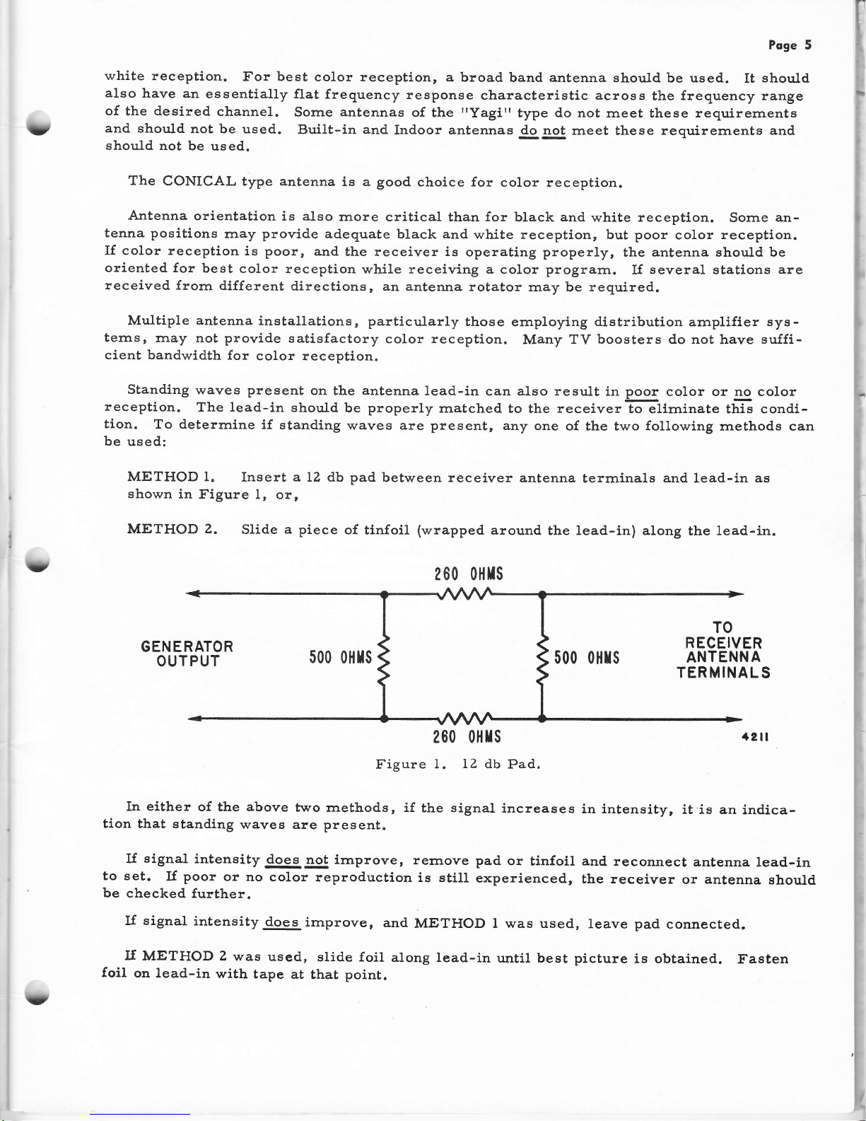
METHOD 1.
Insert a LZ db pad
between receiver
antenna
terrninals
and
lead-in
as
shown
in Figure
1, or,
METHOD 2.
Slide a piece
of tlnfoil
(wrapped
around
the lead-in) atong
the
lead-in.
260 0}lrs
t?
GENERATOR
OUTPUT
500 oHIs
500 o}lrs
TO
RECEIVER
ANTENNA
TERMINALS
+21I
200 0}lrs
Figure
1. 12 db
Pad.
In either
of the above
two rnethods,
if the signal
increases
in lntensity,
it'is an
indica-
tlon
that standing
waves are present.
lf
signal
intensity
does
not irnprove,
rernove pad
or
tinfoil and. reconnect
antenna
lead-in
to set.
I{
poor
or
no
color reproduction
is
stilI
experienced,
the receiver
or
antenna
ehould
be checked
further.
If signal
intensity
does
irnprove,
and
METHOD l was used,
leave
pad
connected.
lf
METHOD 2
was
used,
slide foil
along lead-in
until best picture
is obtained.
Fasten
foil on lead-in
with
tape
at
that
point.
U
Poge
6
PRECAUTIONS
HANDTING
OF
CHASSIS
The
picture
tube used
in
this
chassis
is rnuch
rnore
fragile than
any black
and white
pic-
ture
tube. The
possibility
of
accidental
breakage
is increased
because
of
additional
assem-
blies mounted
on the
neck of the tube.
The
foltowing
precautions
should be taken.
t. It
is irnportant that
ehatterproof
goggles,
heavy
gloves and
a
protective apron
be
worn while handling
or
installing
a
picture
tube.
2. Do not
slide
the
assernblies
rnounted
on
the
neck of the
picture
tube
hastily
or
care-
lessly,
and
without
observing the
procedures
given.
3. Scratching,
burnping or excessive
pressure
on
the
picture
tube
can
result
in
an ex-
plosion
of considerable violence.
The
circuits of this chassis
are
more
nunierous
and cornplex than
in black
and white
re-
ceivers.
Rough or careless
handling
increases the
possibility of
accidental circuit
faiLures.
HIGH VOLTAGE
WAR,NING
Very
htgh
voltage
is
present at sorne
points in this
receiver.
The
20,000 volt
high
volt-
age
regulated supply has
sufflcient energy
to cause
severe injury
or
death.
It ls
irnperatlve that the
following high voltage
precautions
be observed.
1.
Operation
of the
set outside of the
cabinet
or with the
cabinet
back
removed
is a
po-
tentlal
shock hazard.
Z. Severe
shock
can
result
without
rnaking
physical contact
with
any
high voltage
sources.
At all
tirnes
when the
receiver
is operating,
keep
at least
3rr
away
frorn
all points
where
high
voltage
is
present.
3. This
set usea
a rnetal coned
picture
tube
that
is
protected
by a covering
insulator
(boot).
At the
front edge of
the tube
near the
rnetal-to-glass
seal
,
there
is consid-
erable
shock hazardwithln
a distance
of
approxirnately
3'r
frorn
this edge.
X.NAY WARNING
'When
the
set is operating,
the
screen
of the
picture tube
radiates
soft
X-Rays.
These
are norrnally
absorbed
in the
safety
glass front,
but
operation
of the
receiver
outside
the
cabinet
leaves the
screen
unprotected.
This
results
in
a focal
point of these
X-Rays
at
a'
bout
9r'in
front
of the
central
screen
area. Exposure
within
this
area
for more
than
l7
hours
a
week inay
cause
physical injury.
The
X-Rays
are weaker
around
the
edge
and
sldes of the tube.
Physical
exposure
time
around
this
area is unlirnited.
When
maklng
adjustrnents
with
an
r.rrprotected
picture
tube,
avold
rernaining
in the
area
directly
ln front of the
plcture tube
for
rrrore than
the
17 hours
per
week
tirne
lirnit.
If
it
becornes
necessary,
slrield the
front
of the
tube
with
plate
glass
(at
least
l/4"
thick).
Thls
will
absorb
all X-Rays
from the
front
area of the
screen.
Y
(
t(
U,(
"t
I
t
Poge
7
PRELI'WNARY
SERVICE
ADJUSTMENTS
It is lmportant
that any
prelirninary
service adjustrnents
be
rnade before the color set-up
adjustrnents
to
prevent
upselting
color
purity
or
convergence.
Carefully check, and
if necessarlr
rnake the following
adjustrnents
in
the
order listed be-
Iow.
CHANNET
STUGS
The setting
of
the
Fine
Tuning
control
and
Channel Slugs
are
rnuch more critical
for
col-
or
reception.
Be sure
the correct
point
of tuning, as described
below, oscurs at
approxirnately
rnid-
rotation
of the Fine
Tuning control.
IMPORTANT:
If the
Channel Slug
or
Fine Tuning
control is slightly
rnisadjusted for a black and
white
prograrn,
the
picture
and
sound
rnay
still be
acceptable.
With the
same
Channel Slug
and
Fine
Tuning
control setting for a
color
prograrn,
the
picture
rnaygg!
E
t. color.
The
customer
should
be farniliarized with
the irnportance of
correctly
setting
the Fine
Tuning
control.
If
Channel Slugs
need
adjustment, proceed
as follows:
A.
Turn on set.
Allow
15
rninutes for
warrn-up.
B.
Tune
in station
and set for
norrnal picture and
sound.
C. Set Fine
Tuning control at approxirnately
rnid-rotation.
IMPORTANT:
See f
igure 2 for position
of
Fine
Tuning
carn for
rnid-rotatlon
setting.
When
carn
is
in thls
posltLon,
Fine Tuning control is at rnid-
rotation.
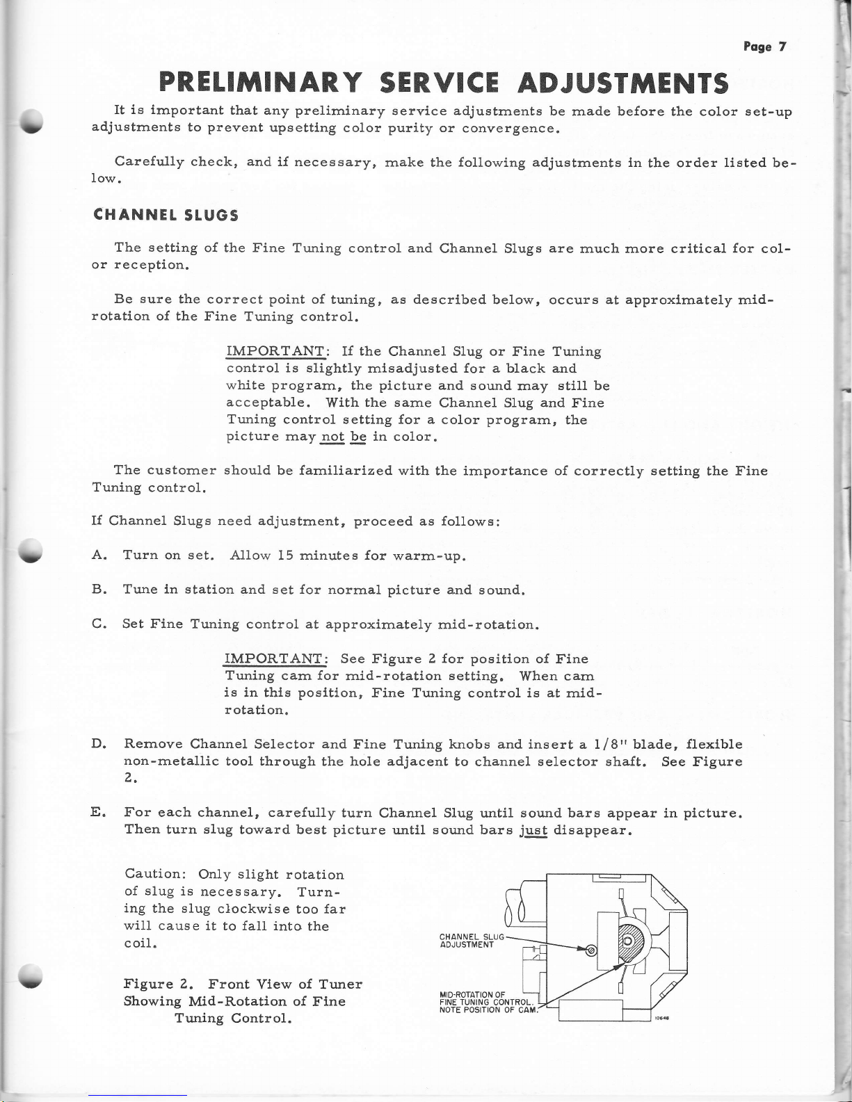
D.
Rernove
Channel Selector and
Fine Tuning knobs
and
insert a Lf
8"
blade,
flexlble
non-rnetallic
tool through
the hole
adjacent
to channel
selector shaft.
See f
igure
z,
E.
For
each channel, carefully
turn
Channel SIug until
sound bars appear
in
plcture.
Then
turn
slug
toward best
picture
until
sound bars
just
disappear.
Caution:
Only
slight
rotation
of
slug
is
necessary.
Turn-
ing
the slug
clockwise
too far
will
cause
it to fall into
the
coil.
Figure 2.
Front
View
of
Tuner
Showing
Mid-Rotation
of
Fine
Tuning Control.
f
?
CHANNEL SLUG
ADJUSTMENT
t1
Pege
8
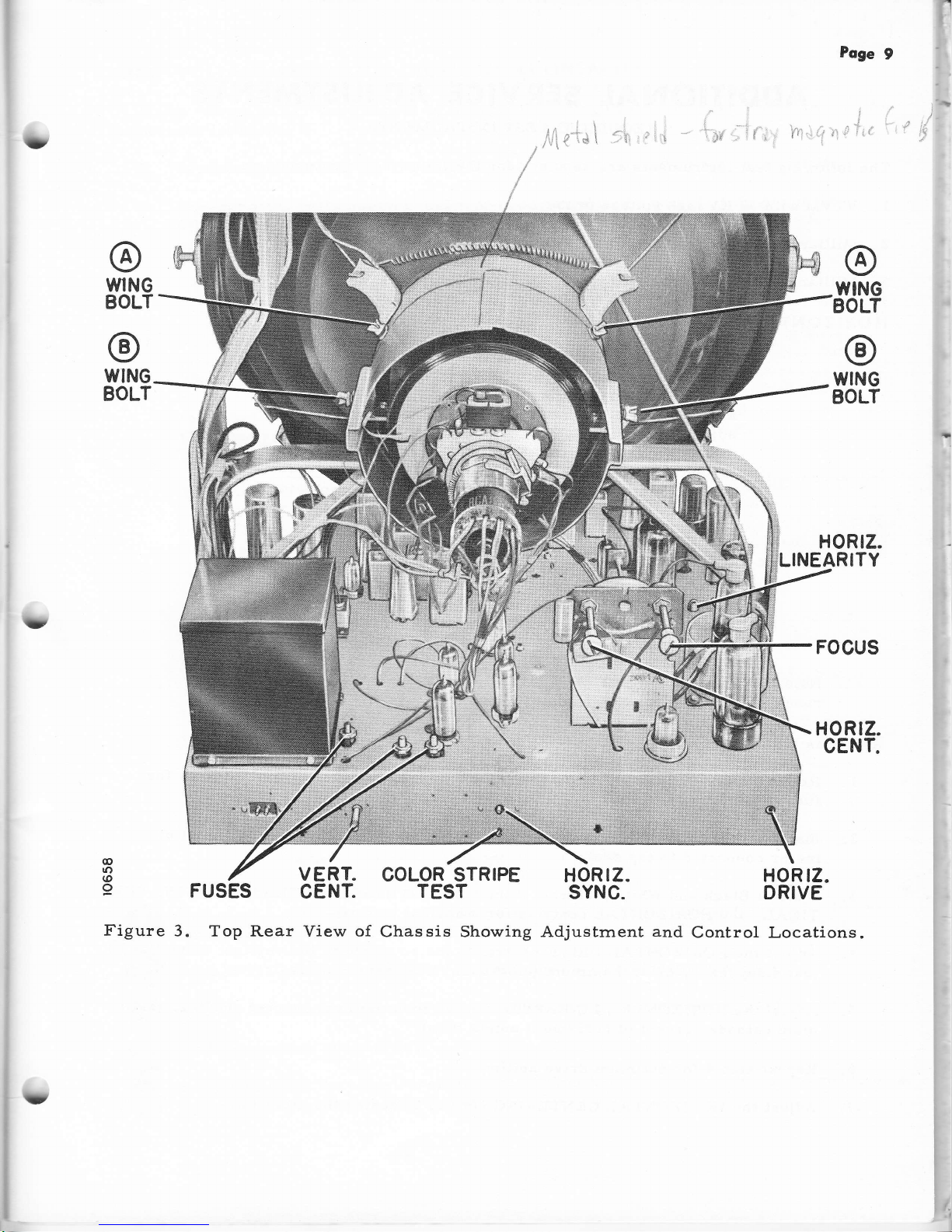
HORIZONTAL SNYC
The
picture should rern,ain
in sync throughout the
range
of the
Horlzontal
Hold
control,
even
when interrupting the signal
by switching on and off station. See Figure
3 for
location
of
Horizontal
frequency
control.
The
HORIZONTAL SYNC
adjustrnent is
per{orrned the sarne way
as
on
a black
and
white
receiver
using the rnultivibrator
and discriminator
rnethod
for
horlzontal
sync
and
sweep.
For
exarnple,
all
20Y4 series
black and white
receivers use this rnethod.
RASTER TItT ADJUST}IENT
If
raster is tilted, loosen the
@g
wing
bolts
(A) (see
Figure 3)
and rotate
yoke until
picture
is straight.
Tighten the
wing bo1ts.
Note:
tr'igure 3
shows
the
location of only
two wing
bolts
(A).
The third
is located on
the sarrre bracket
directly
underneath the
picture
tube
neck.
HEIGHI
AND LINEARITY
These
adjustrnents
are
adjusted
the
sarne way on the color
receiver
as
on
a black
and
whlte
receiver.
Be
sure to adjust for best
height and linearity
with the
picture
set at
ap-
proxirnately
llZt' beyond
the top
and bottorn lirnits
of
the
rnask. The HEIGHT
and
LINEAR-
ITY controls
are located behind
the
rernovable
panel
under
the
safety
glass frarne.
Re-
rrrove
the
four
screws frorn
under
bottorn edge of the
panel.
Panel
can then
be
easily
re-
rnoved.
Adjusting
HEIGHT
and
LINEARITY
after
color
set-up
adjustrnents rnay upset
color
purity and
convergence.
Flowever,
if only
a
slight touch-up
is
necessary
following color
set-up
adjustrnents,
the
effectEy
be negligible.
HOR!ZONTAt DRIVE
Adjust
the
HORIZONTAL DRIVE
control to a
point
where the
white vertical
line(s)
just
disappear, or
to
rna><irnurn if drive lines
do not appear. See Figure
3 for control
location.
Ma<irnurn
drive is at
rnaxirnurn
(cornpletely
clockwise)
rotation
of the control.
HORIZONTAL
AND VERTICAL CENTER.ING
Adjust
for
proper
horizontal and
vertical centering.
See
Figure 3
for control
locations.
(
(
l}
rll,
WNG
BOLT
Poge
9
TYING
tsOLT
@
WING
BOLT
HORTZ.
NEARITY
FOCUS
@
WING
BOLT
.t
,1,:.:
trt'tj:i!,li:il:!ll:a,,irj:
:.-:::::-:ra:::ri:!i:,.4
j
c;!r'
:i
r'i:l:ii.lli:i:lef
!iia:i:l::;!:.
':.:.r
:;r :r:.:ii.r:!t1t1{1ij:
rii:
!,-:i:,i.:rirrielr::r!$;1r.
:iu:1i!i;1iiN.,:;!:.45;d
ffi"}
..'r
E#Sl
.',
lrr:i;;l.,:t;I::tti:::i;i:ti:
rt:tr
i:da!ii!i:!iii:::j:i!r
ti;;l:t
i
HORTZ.
CENT.
@
tO
@
9
FUSES
Figure
3. Top
Rear View
of
COLOR STRIPE
TEST
Chas
sis
Showing
VERT.
CENT.
HOR
rZ.
SYNC.
HOR
rZ.
DR!VE
Adjustrnent
and
Control Locations.
:
Poge
l0
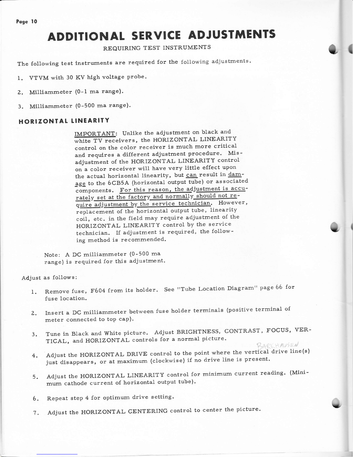
ADDITIONAL
SERVICE
ADJUSTMENTS
REQUIRING
TEST
INSTRUMENTS
The
{ollowing
test
lnstrurnents
are
required
for the
1. VTVM
with
30
KV
high
voltage
probe'
Z. Milllarnrneter
(0
-
I
rna
range).
3. Milliarnrneter
(0-500
rna
range).
HORIZONTAL
TINEARITY
following
adjustments.
Hfi
ffi
:,,""1::";:"#*E'ff;:'rJiHxili,
controlonthecolorreceiverisrnuchrnorecritical
and
requlres
a different
adjustment
procedure'
Mis-
adjustrnent
of the
HoRIzoNTAL
LINEARITY
control
onacolorreceiverwillhaveverylittleeffectupon
the
actual
horizontal
llnearity,
but
can
result
i'44-
ggg to
the
6CB5A
(horizontal
output
tube)
or
associated
colrpon"nt".
For
this
reason,
the
adjustnle-nt
iF
accu-
.rtuiy@v@]Jv
should
not
re-
iffim'ffi,,IjriJ"''
.oiI
,
"t..
in the
field
rnay
require
adjustment
of
the
HORIZONTAL
LINEARITY
control
by
the
service
technician.
If
adjustment
is
required'
the
follow-
ing method
is
recomrnended'
Note:
A
DC milliarnmeter
(0-500 ma
range)
is
required
for this
adjustrnent'
Adjust
as
follows:
l. Rernove
fuse,
F604
frorn
its
holder.
See
"Tube
Location
Diagrarnil
page 66
for
fuse
location.
z. Insert
a
Dc
rnilliarnrneter
between
fuse
holder
terrninals
(positive
terrninal
of
rneLer
connected
to
toP
caP)'
3.
Tune
in Black
and white
picture.
Adjust
BRIGHTNESS,
CoNTRAST'
FOCUS'
vER-
TICAL,
and
HORIZONTAL
controls
for
a norrnal
picture'
i
,,
:.-
4.
Adjust
the HoRIZoNTAL
DRIVE
control
to
the
point
where
the
vertical
drive
line(s)
justdisappears,oratrnaxirnum(clockwise)ifnodrivelineispresent.
5.
Adjust
the HoRIZoNTAL
LINEARITY
control
for
minimurrl
current
reading'
(Mini-
rnurn
cathode
current
of
horizontal
output
tube)'
Repeat
step
4
for optirnurn
drive
setting'
AdjusttheHORIZoNTALCENTERINGcontroltocenterthepicture.
{
6.
U

T
il
i
;
r
I
Poge
I I
HIGH
VOLIAGE
REGUTATOR.
HORIZONTAL
LINEAR'ITY
A
line
voltage
of I 1?
volts
should
be
rnaintained
during
this
adjustrnent.
See
Figure
3
for
adjustrnent
locations .
?
Caution:
Milliarnmeter
leads
will
be at B
p}us
potential
(380
volts).
Be
sure
to
isolate
rneter
frorn chassis'
10.
Readjust
the HoRIZONTAL
LiNEARITY
coil
in the
direction
o{
less
inductance,
(slug
moving
outward
frorn coil)
until
the
cathode
current
of the
Horizontal
Output
tube
is
approxirnately
200
rnilliamperes.
Do
not
exceed
210 rnilliarnpeles
as
lin-
earity
is disrupted
above
this
value
of current.
The
High
voltage
should
read
in
the
range
o{
tg.5
to
ZL.5 KV,
with
regulator
current
of
750
to
I000
microamperes'
optirnurn
setting
is
200
rnilliarnperes
output
tube
current
with
20 KV
high
voltage
and
regulator
current
of
950
rnicroamperes'
For
line
voltages
between
105
and 11?
votts,
adjust
HORIZONTAL
LINEARITY
control
accordingly.
For
exarnple,
aline
voltage
of
110
volts
results
in
a
ratio
of
I10
llLT
or.9i
(r"irrg
117 volts
as standard).
Therefore,
the
high
voltage
would
be
set
at.
.g4
x
20,000
volts
or
18,800
volts.
Maxirnurn
Horizontal
Output
tube
cur-
rent
becornes
.94
x 210 rnilliarnperes
or 19?
rnilliarrrperes
and rninirnurn
optirnurn
regulator
current .94
x 750 rnicroarnperes'
Rernove
rneters
and
replace
test
jurnper
wire
and
fuse'
Repeat
steps
4
andT
if'
necessary.
overscan
should
be
approxirnately
I
Ll4
inch
each
side"
Il.
Recheck
vertical
height
and
linearity.
Overscan
should
be
at least
LIZ
incln
at top
and bottorn.
8. Set
the BRIGHTNESS
and
CONTRAST
9.
Connect
a
DC
rnilliarnrneter
(0-1
rna)
6FK4
regulator
tube
(positive
lead to
.rneter
insertion.
IMPORTANT:
Before
adjustrnents
(Purity or
you have.
controls
to minirnurn,
(
for bearn
cutoff).
in
series
with the
cathode
(Pin
#i)
of the
cathode).
A test
jumper
is
provided
for
rl7
o
@
o
@
o
COLOR.
sET
-
UP
ADJUSTMENTS
rnaking
any
color
set-uP
Convergence)
be
sure
read
page
3,
"IMPORTANT
COLOR
SET-UP
HINTS",
and
followed
through
with
the
instructions,
checked
and rnade
any necessary
prelirninary
service
adjustrnents,
checked
the
receiver
f6r
perforrnance
after the
prelirninary
service
adjustrnents,
read
this
section
cornPletelY,
decided
whether
the
color
receiver
needs
a
rttouch-up"
of
so ne color
adjustrnents
or
a
ncornpleterr
color
set-up
adjustrnent'
U
Poge
12
A
"cornplete'r
color
set-up
adjustrnent
consists
of the
following
steps
in
the order
given.
I
CENTER
STATIC
CONVERGENCE
(DC).
See Figure
lr.
II
COLOR
PURITY
III
CONVERGENCE
IV
TOUCH-UP
OF PURITY
V
TOUCH-UP
OF
CONVERGENCE
I
VI BLACK
AND
WHITE
TRACKING
(Good
black
of
the
Brightness
control)
If the
receiver
requires
a
trcornpleterl
set-up
adjustment,
rnake
all
adjustrnents
listed,
including
the
'rtouch-up'r
adjust-
rnents
"
If the
receiver
requires
only
a
rrtouch-up"
of sorne
color
adjustrnents,
rnake
those
adjustrnents
only.
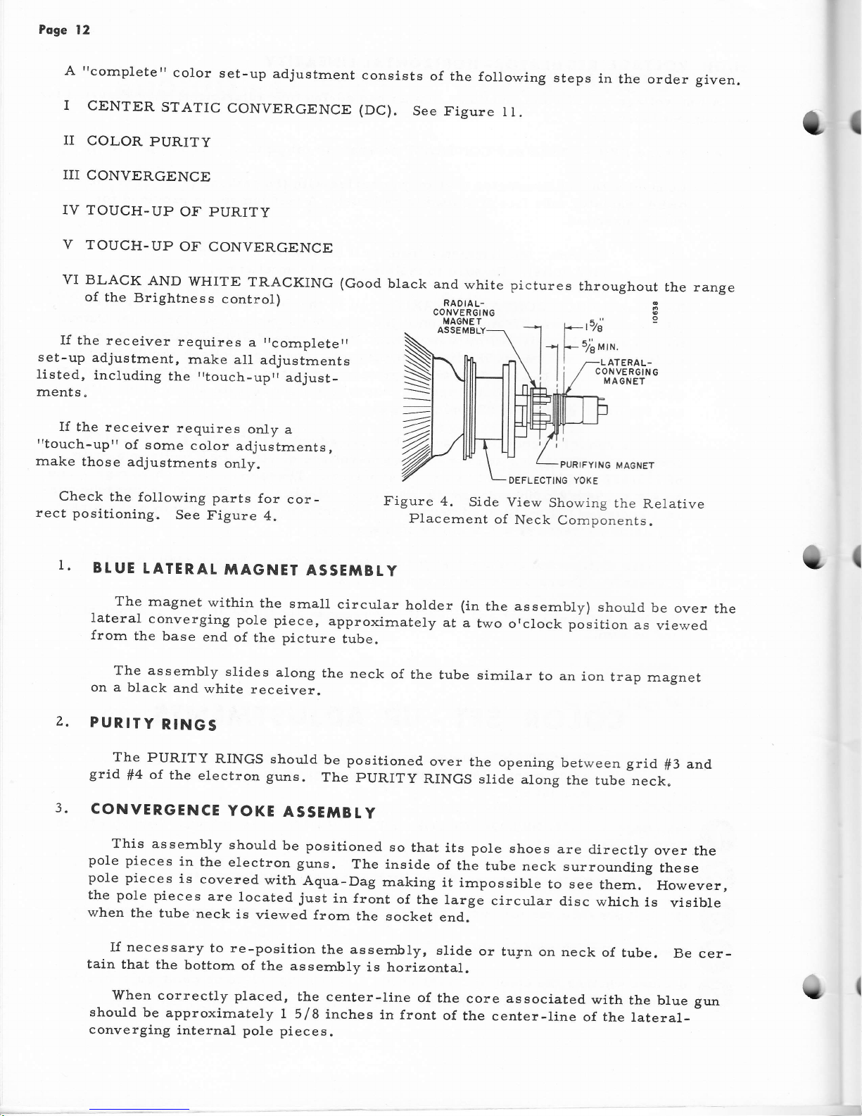
Check
the
{ollowing
parts
for
cor-
rect
positioning.
See
Figure
4.
ASSEMBLY
PURIFYING
MAGNET
DEFLECTTNG YOKE
Figure
4.
Si.de
View
Showing
the
Relative
Placernent
o{
Neck Cornponents.
and
white
RADIAL-
CONVER6ING
MAGNE T
hout
9
RAL-
;RGING
NET
the range
I
I.
z.
BtUE
TATERAL
MAGNET
ASSETIBtY
The
rnagnet
within
the
sma1l
circular
holder
(in
the assernbly)
should
be
over
the
lateral
converging
pole
piece,
approximately
at
a
two
orclock
position
as
viewed
from
the
base
end
of
the
picture
tube.
The assernbly
stides
along
the
neck
of the
tube
sirnilar
to an
ion
trap
rnagnet
on
a
black
and
white
receiver.
PURITY
RINGS
The
PURITY
RINGS
should
be positioned
grid
ff4
of
the
electron
guns.
The
pURITy
CONVERGENCE
YOKE
ASSE'ITBtY
over
the opening
between
grid
f3
and
RINGS
slide
along
the
tube
neck.
This
assernbly
should
be positioned
so
that
its pole
shoes
are
directly
over
the
pole
pieces
in
the
electron
guns.
The
inside
of
the
tube neck
surrounding
these
pole
pieces
is
covered
with
Aqua-Dag
rnaking
it
irnpossible
to see
thern.
However,
the pole
pieces
are
located
just
in front
of
thl
targe
circuLar
disc
which
is
visible
when
the
tube
neck
is
viewed
frorn
the socket
end.
If necessary
to
re-position
the assembly,
slid.e
or
tu3:n
on neck
of
tube.
Be cer-
tain
that
the
bottorn
of
the
assernbly
is
horizontal.
'When
correctly
placed,
the center-line
of the
core associated
with
the
blue
gun
should
be
approximately
I 5/8
inches
in front
of
the center-line
of the
lateral-
converging
internal
pole
pieces.
u
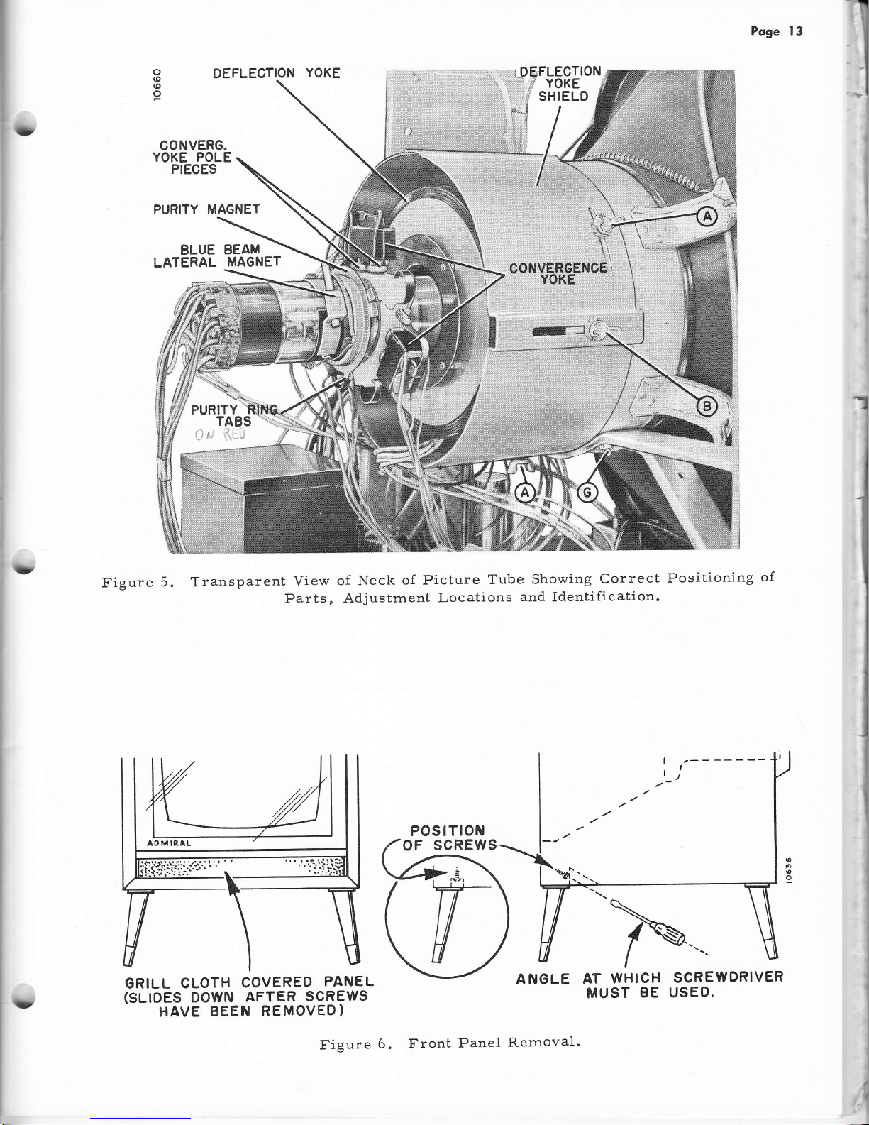
Poge 13
DEFLECTION
YOKE
CONVERG.
YOKE POLE
PIECES
PURITY MAGNET
BLUE
BEAM
LATERAL
MAGNET
/:.
-1
&
tla
Figure
5. Transparent
View
of
Neck
of Picture
Tube
Showing
Correct
Positioning
of
Parts,
Adjustrnent
Locations
and
Identification.
o
(o
(o
o
D
t
'1
i
I
I
I
GRILL
CLOTH
COVERED
PANEL
(SLIOES
DOWN
AFTER
SCREWS
HAVE
BEEN
REMOVED)
ANGLE
AT
WHICH
MUST
BE
SCREWDRIVER
USED.
ru
POSTTTON
OF
SCREWS
rD
Figure
6. Front
Panel
Rernoval
.
Poge
14
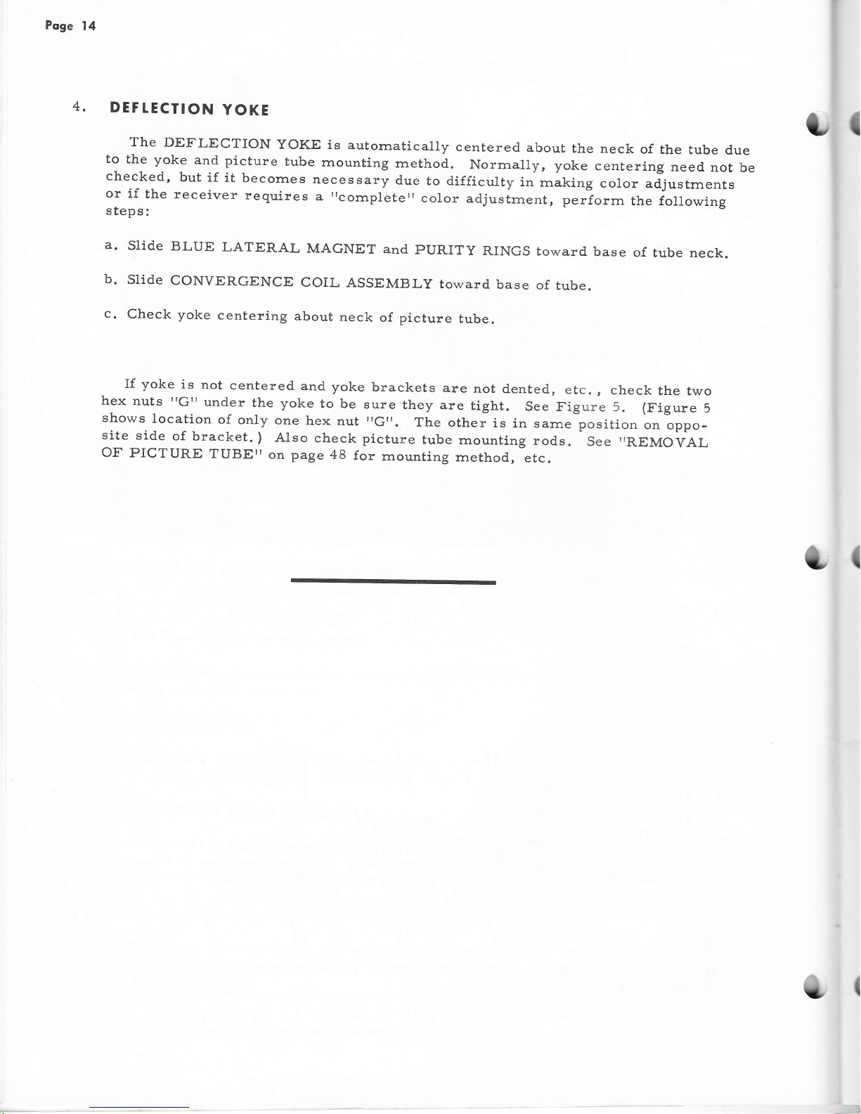
4.
DEF
TECTION
YOKE
The
DEFLECTION
YOKE is
autornatically
centered
about
the neck
of
the
tube
d.ue
to
the yoke
and
picture
tube
rnounting
rnethod.
Norrnally, yoke
centering
need
not
be
checked,
but
if
it
becornes
necessary
due
to difficulty
in
rnaking
color
adjustrnents
or if
the receiver
requires
aricornpleterrcolor
adjustrnent,
perforrn
the following
steps:
a'
Slide
BLUE
LATERAL
MAGNET
and
PURITY
RINGS toward
base
of
tube neck.
b.
slide
CONVERGENCE
coIL
ASSEMBLy
toward
base
of
tube.
c.
Check
yoke
centering
about
neck
of picture
tube.
lf
yoke
is
not
centered.
and
yoke
brackets
are
not
dented,
etc.,
check
the two
hex
nuts
"G'r
under
the yoke
to be
sure
they
are
tight.
see
Figure 5.
(Figure
5
shows
location
of
only
one
hex
nut
,Gtr.
The
other
is
in sarne
position
on oppo-
site
side
of
bracket.
)
AIso
check picture
tube
mounting
rods.
See
,REMO1;AL
OF PICTURE
TUBETT
on
page
48
{or
rnounting
rnethod,
etc.
I
1
{
Poge
15
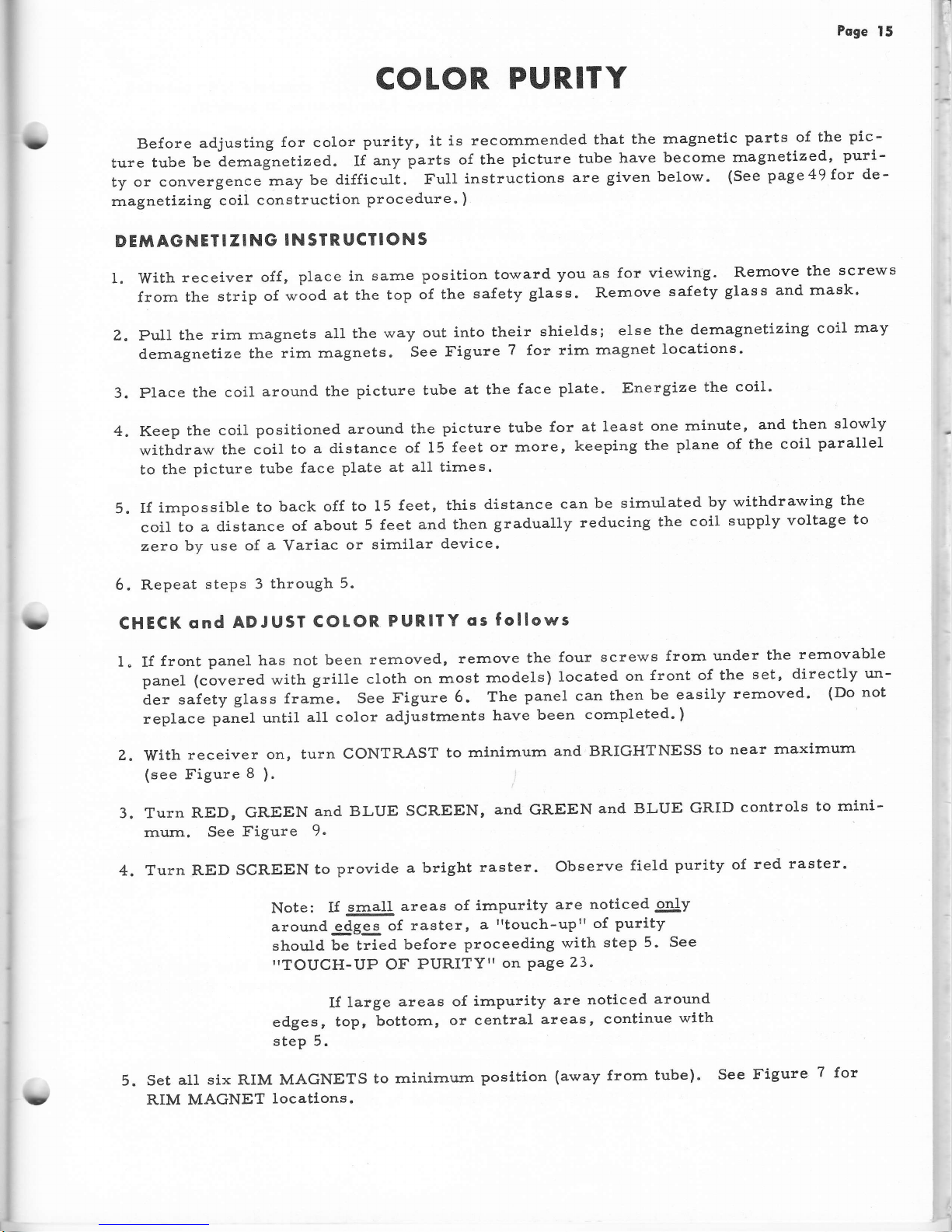
COTOR
PURITY
Before
adjusting
for
color
purity,
it is
recomrnended
that
the
magnetlc
parts
of the
pic-
ture
tube
be
dernagnetized..
If
any
parts
of the
picture tube
have
become
rnagnetized,
puri-
ty
or conv.rgurr".
rrray
be
difficult.
FuII
instructions
are
given below.
(See
page49f'or
de'
rnagnetizing
coil
construction
procedure.
)
DEMAGNETI
ZING
IN
SIR
UCIIONS
I. With
receiver
off
,
place in
sarne
position
toward
you
as for
viewing.
Rernove
the
screws
from the
strip
of wood
at the
top
of the
safety
gIass. Rernove
safety
glass
and rnask'
Z.
pull
lhe
rirn rnagnets
all
the
way
out
into their
shields;
else
the
dernagnetizing
coil
rnay
dernagnetize
tirre
rirn
rnagnets"
See
I'igure
?
for
rirn
rnagnet
locations.
3. Place
the
coil
around
the
picture tube
at
the
face
plate.
Energize
the
coil'
4.
Keep
the
coil
positioned around
the
picture tube
for
at least
one rninute,
and then
slowly
withdraw
the coil
to
a distance
of 15
feet or rnore,
keeping
the
plane of the
coil
parallel
to the
picture
tube
{ace
plate
at all times.
5.
If
irnpossible
to
back off
to 15
feet, this
distance
can
be simulated
by withdrawing
the
coil
to
a
distance of
about
5
feet
and then
gradually
reducing
the
coil
supply
voltage
to
zero
by use of
a
Variac
or
sirnilar
device.
6. Repeat
steps
3
through
5.
CHECK
ond
ADJUSI
COtOR.
PURIf
Y
os
follows
I. If
{ront
panel
has
not been
rernoved,
rernove
the
four
screws
frorn under
the
rernovable
panel
(covered with
grille
cloth
on rnost
rnodels)
located
on
front of the
set,
directly
un-
der
safety
glass
frarne.
See Figure
6.
The
panel can
then
be easily
rernoved'
(Do
not
replace
panel until
all color
adjustrnents
have
been
cornpleted.
)
Z.
With
receiver
on, turn
CONTRAST
to rninirnurn
and BRIGHTNESS
to
near
rnaxirnurn
(see
Figure
8
).
3. Turn
RED, GREEN
and BLUE
SCREEN,
and
GREEN
and BLUE
GRID
controls
to
rnini-
rnum.
See
Figure
9-
4. Turn
RED
SCREEN
to
provide
a bright
raster.
Observe
field
purity of
red
raster.
Note:
If
@lI
areas
of irnpurity
are
noticed
only
around-4gSg
of
raster,
a
rrtouch-up"
of
purity
should
be tried
before
proceeding
with
step 5.
See
"TOUCH-UP
OF
PURITY"
on
Page
23.
If
large
areas
of
irnpurity
are noticed
around
edges,
topr
bottorn,
or
central
areas,
continue
with
step 5.
5. Set
alt
six RIM MAGNETS
to
rninirnurn
posltion
(away
frorn
tube).
See
Figure
7
for
RIM MAGNET
locatlons.
3
?
U
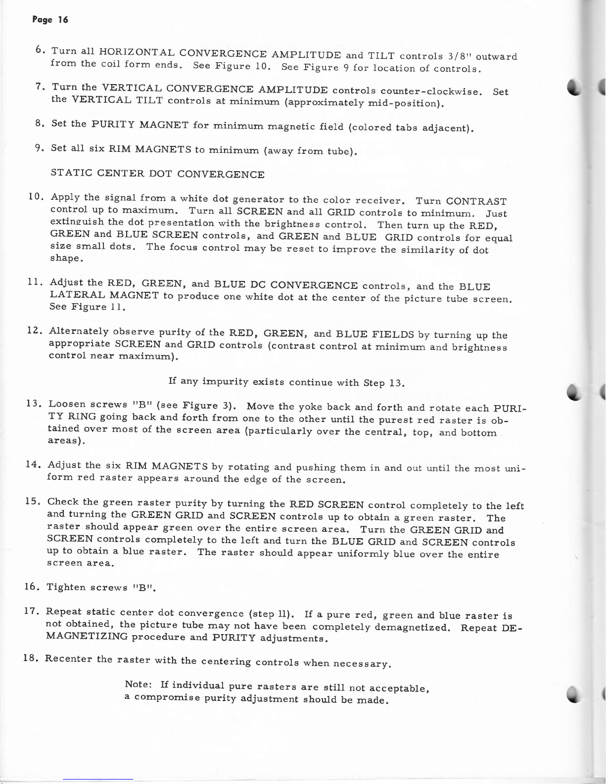
6.
Poge
15
Turn
all
HORIZONTAL
CONVERGENCE
frorn
the
coil
form
end.s.
See
Figure
I0.
7'
Turn
the
YERTICAL
CONVERGENCE
AMPLITUDE
controls
counter-clockwise.
Set
the
VERTICAL
TILT
controls
at
rninirnurn
(approxirnately
rnid-position).
8' Set
the
PURITY
MAGNET
for
minimurn
magnetic
field (colored
tabs adjacent).
9.
set all
six
RIM
MAGNETS
to rninimurn
(away
frorn
tube).
STATIC
CENTER
DOT
CONVERGENCE
t1.
App1y
the signal
frorn
a
white
dot
generator
to
the
color receiver.
Turn
CONTRAST
control
up
to
rnaximurn.
Turn all
SCREEN
and all
GRID
controls
to
rninirnurn"
Just
extinsuish
the dot
presentatlon
with
the
brightness
control.
Then
turn up
the
RED,
GREEN
and
BLUE
SCREEN
controls,
and
GREEN
and
BLUE
GRID
controls
for
equal
size
small
dots-
The focus
control
rnay
be
reset
to irnprove
the sirnilarity
of
dot
shape.
Adjust
the
RED,
GREEN,
and
BLUE
Dc
CONVERGENCE
controls,
and
the
BLUE
LATERAL
MAGNET
to
produce
one
white
dot
at
the
center
of
the
picture
tube screen.
See Figure
I
1.
AMPLITUDE
and
TILT controls
3/8"
outward
See
figure
9
for
location
of controls.
turning
up
the
and
brightness
(
10.
lz.
13.
14.
15.
Alternately
observe
purity
of the
RED,
GREEN, and
BLUE
FIELDS
by
appropriate
SCREEN
and
GRID
controls (contrast
conlrol
at
rninirnum
control
near
rnaxirnurn).
If
any
hnpurity
exists
continue
with
Step
13.
Loosen
screws
IBrr(see
Figure
3).
Move
the yoke
back
and
forth and
rotate
each
pURI-
TY
RING going
back
and
forth
frorn
one
to the
other
until
the
purest
red.
raster
is
ob-
tained
over
most
of
the
screen
area
(particularly
over
the
central
,
top, and
bottorn
areas
).
Adjust
the
six
RIM
MAGNETS
by
rotating
and
pushing
thern in and
out until
the rnost uni-
forrn
red
raster
appears
around
the
edge
of the
screen.
Check the green
raster
purity
by
turning
the
RED
SCREEN
control
cornpletely
to
the left
and
turning
the
GREEN
GRID and
SCREEN
controls
up to
obtain a green
raster.
The
raster
should
appear
green
over
the
entire
screen
area.
Turn
the
GREEN
GRID
and
SCREEN
controls
cornpletely
to the
left and
turn
the
BLUE
GRID
and
SCREEN
controls
up
to
obtain a
blue raster.
The raster
should
appear
uniforrnly
blue over
the
entire
screen
area.
16.
Tighten
screws
rrBrr.
17.
Repeat static
center
dot
convergence
(step11).
Ifapure
red,
green
andblue
raster
is
not
obtained,
the picture
tube
rnay
not
have
been
cornpletely
demagnetized.
Repeat
DE-
MAGNETIZING
procedure
and
pURITy
adjustments.
18.
Recenter
the
raster
with
the
centering
controls
when
necessary.
(
Note:
If individual
pure
rasters
are
still
not
acceptable,
a
cornprornise
purity
adjustrnent
should
be
rnad.e.
(
(}
?
TUNER
MOUNTING
BRACKET
ANTENNA
TERMINALS
RETAIN!NG
RODS
CONVERGENCE
YOKE
PLUG
&
SOCKET
GROUND
SPRING
RIM MAGNET
Poge
17
NUT
PLASTIC
BOOT
RETAIN
ING
ROD
NUTS
RIM
MAGNETS
SPEAKER
SOCKET
HIGH
VOLTAGE
INTERLOCK
(
MOUNTED
BEHIND
SAFETY
GLASS.
)
o,
rO
(o
o
?'.['..ttJl?,[
&
SOCKECT
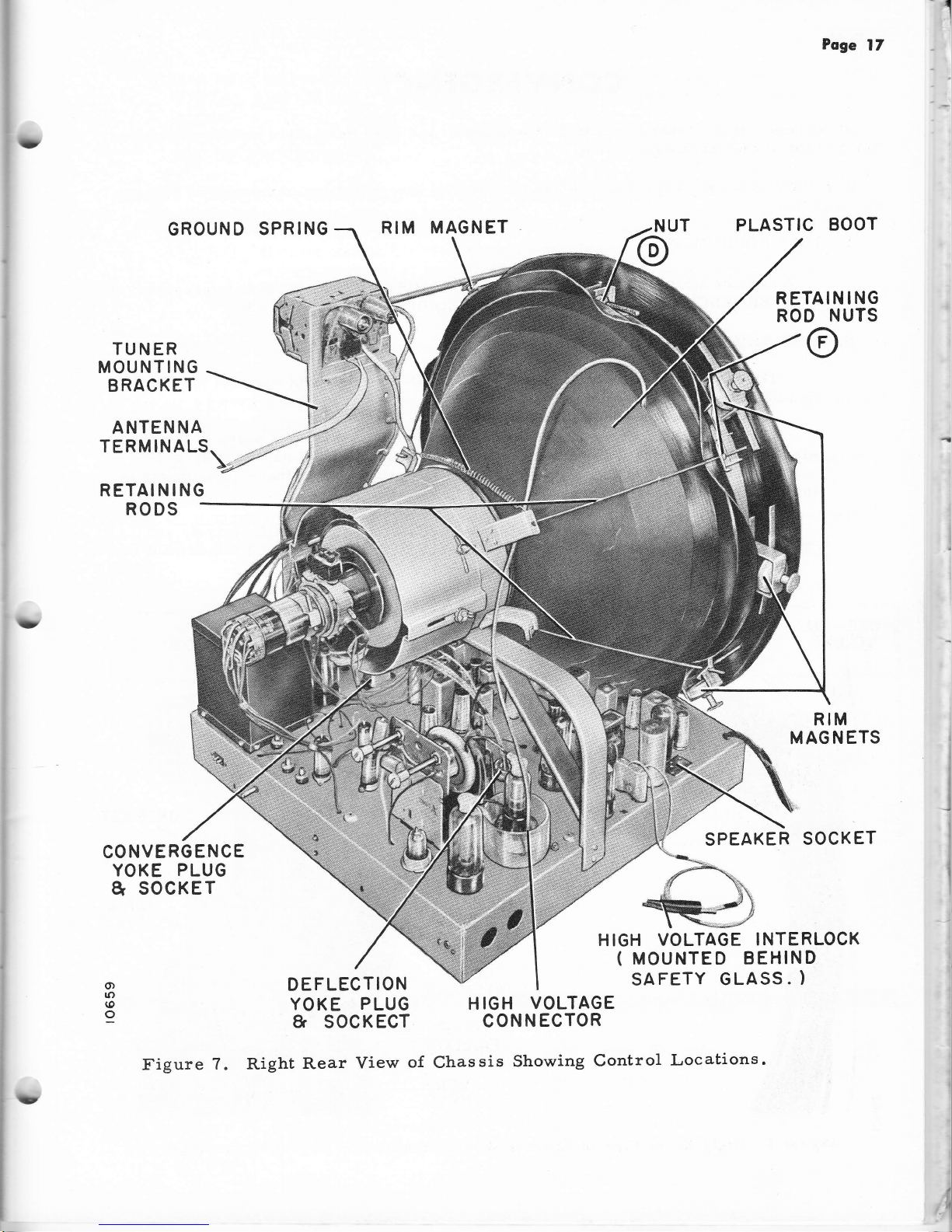
Figure
7. Right
Rear
View
o{
H
IGH
VOLTAGE
CONN
ECTOR
Chassis
Showing
Control
Locations.

Poge
18
CONVERGENCE
convergence
is
necessary
so
that
the
Red,
Green and
Blue
Bearns
are
rnuch
of
the
screen
area
as possible.
converged
over
as
In
general,
very good
convergence
can
be
achieved
over
screen
area.
A.
TEST
EQUIPMENT
85fl0
(plus
or
minus
5a/o)
of.
t]ne
A suitable
W'hite
Dot
Generator (such
as
ADMIRAL
Model
TE-100)
is
necessary
for
CONVERGENCE
adjustrnents.
See
',TEST
EQUIpMENT,,
on
page
3g.
B.
LOCATION
OF CONTROLS
The
STATIC
Convergence
controls
are
located
on
the
fronl
apron
of the
chassis
and
the
Blue
Lateral Magnet in
its
holder
on
the
tube neck.
See Figure
5.
The
DYNAMIC
Convergence
controls
are
located
on the front
apron
of
the chas-
sis.
Rernove
the four
screws frorn
under
the rernovable
front panel
for
access
to
controls.
The panel
is
then
easily
rernoved.
Identification
of
these adjustrnents
is
indicated
in Figure 9
and
on
a
label
on the chassis
apron.
ThC Effects
o{
the
HORIZONTAL
and
VERTICAL
AMPLITUDE
controls
and
TILT
controls
are indicated
in
Figure
12.
The
HORIZONTAL
TILT adjustrnent
for
I
(
OFF-ON
VOLUME
BRIGHTNESS
CHANNEL
SELEGTOR
CONTRAST
TONE
HORtZ.
HOLD
COLOR
INTENSITY
COLOR
FIOELITY
VERT.
HOLD
(
Figure
8.
Right
Front
Yiew of
Chassis
Showing
Location of
Operating
Controls"
L
?
lU
Poge
19
each color
will
cause
the
peaks
of
the
horizontal
waveforrn,
forrned
when
the HORI-
ZONTAL
AMPLITUDE
controls
are
advanced
fu1ly
to the
right, to
rnove
frorn
side
to
side.
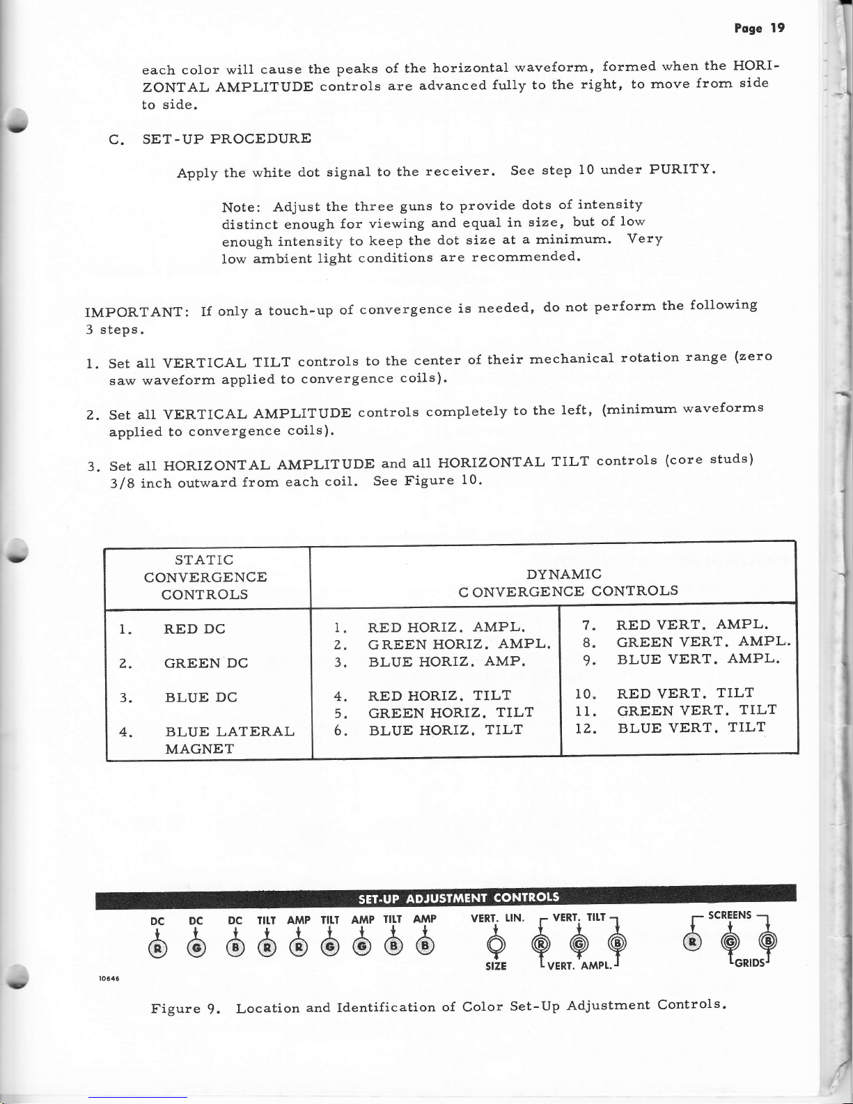
C.
SET-UP
PROCEDURE
Apply
the
white
d.ot signal
to the
receiver.
See
step
10 under
PURITY.
Note:
Adjust
the three
guns to
provide
dots
of
intensity
d.istinct enough
for viewing
and equal
in
size, but
of
low
enough
intensity
to
keep the
dot size
at a rninirnurn.
Very
low
ambient
light
conditions
are recomrnended.
iMPORTANT:
If
only
a
touch-up
of
convergence
is
needed,
do
not
perforrn
the
following
3
steps.
1. Set
all
VERTICAL
TILT
controls
to
the
center
of their
rnechanical
rotation
range
(zero
saw waveform
applied
to
convergence
coils).
Z.
Set
all VERTICAL
AMPLITUDE
controls
cornpletely
to the
1eft,
(minirnurn
waveforms
applied
to
convergence
coils).
3.
SEt
A11
HORIZONTAL
AMPLITUDE
ANd
A11
HORIZONTAL
TILT
CONtTO1S
(COTE
StUdS)
3/8
inch
oulward
frorn
each
coil.
See
Figure
10'
STATIC
CONVERGENCE
CONTROLS
DYNAMIC
C ONVERGENCE
CONTROLS
1. RED
DC
Z.
GREEN
DC
3. BLUE
DC
4. BLUE
LATERAL
MAGNET
1
Z
3
4
5
6
RED HORIZ.
AMPL.
GREEN
HORIZ.
AMPL.
BLUE HORIZ.
AMP.
RED
HORIZ.
TTLT
GREEN
HORIZ.
TILT
BLUE HORIZ.
TILT
8
9
RED
VERT.
AMPL.
GREEN
VERT.
AMPL.
BLUE VERT.
AMPL.
10" RED YERT.
TILT
I1. GREEN
VERT.
TILT
LZ.
BLUE
VERT.
TILT
E
b
d l$
,b,5
d
H H
-hj'.
$:3::A
6"Q]$
(D
Figure
9.
Location
and
Identification
of
Color
Set-Up
Adjustrnent
Controls'
Poge
20
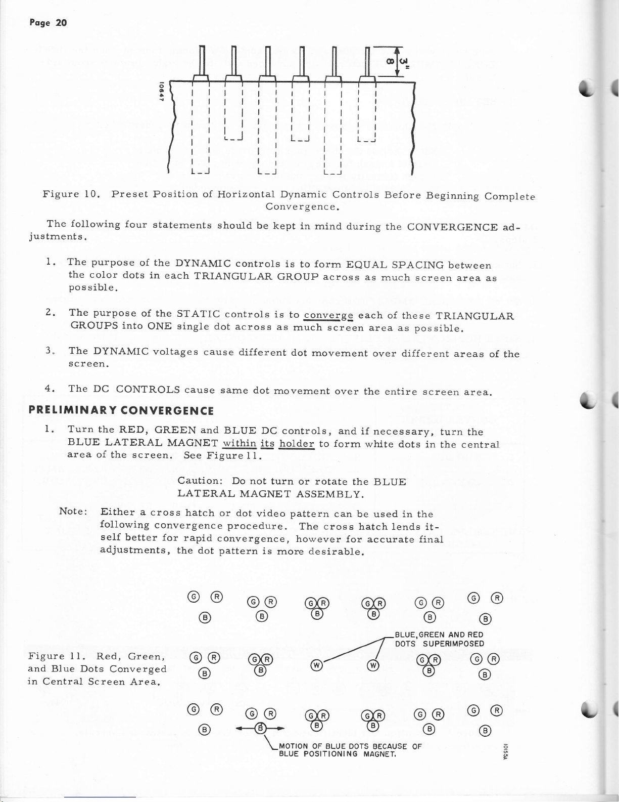
Figure
10.
Preset Position of
The
following
four
staternents
justrnents.
Horizontal
Dynamic
Controls
Be{ore
Beginning
Cornplete
Convergenc e.
should
be
kept
in
rnind
during
the
CONVERGENCE
ad-
o-
o
{
I
I.
The
purpose
of
the
DyNAMIC
controls
is
to
forrn
EeUAL
SPACING
between
the
color
dots
in
each
TR.IANGULAR
GROUP across
as
rnuch screen
area as
pos
sible.
The
purpose
of the
STATIC
controls
is
to converge
each of
these
TRIANGULAR
GROUPS
into
oNE single
dot
across
as
rnuch
screen
area as possible.
The
DYNAMIC
voltages
cause d.ifferent
dot
rnovernent
over
different areas
of
the
screen.
z.
3"
4,
The
DC
CONTROLS
cause
sarrle
d.ot
movement
over
the
entire
screen
PRE t !TIII
N
AR Y
CONVERGE
N
CE
area.
(
I.
Turn the
RED,
GREEN and
BLUE
DC
BLUE
LATERAL
MAGNET
within its
controls, and
if
necessary,
turn
the
holder
to
forrn
white
dots in
the central
@@
@@
@@
BLUE,GREEN AND
RED
DOTS SUPERIMPOSEO
area
of
the screen.
See
Fi.gure
t l.
Caution:
Do not
turn
or
rotate
the
BLUE
LATERAL
MAGNET
ASSEMBLY.
Note:
Either
a
cross
hatch
or dot
video
pattern
can be
used in the
following
convergence
procedure.
The cross
hatch lends
it-
seLf
better
for
rapid
convergence,
however
for accurate final
adjustrnents,
the
dot pattern
is
rnore
desirable.
Figure I 1.
Red, Green,
and
Blue Dots
Converged
in
Central Screen Area.
w
@4
@@
@o
--@+
(,
w
@@
@
@@
@
@@
@
w
@@
@
@@
@
@@
@
@@
@
OF
(
\-MOTION
OF BLUE DOTS
BECAUSE
BLUE
POSITIONING MAGNEI
[-
i
i
1
Poge
2I
+
l
t
a
+
a
+
a
I
+
a
i
a
+
I
I
a
I
I
v
a
I
V
t
I
a
g
?
v
a
I
V
?
I
?
I
V
a
I
I
t
{
1
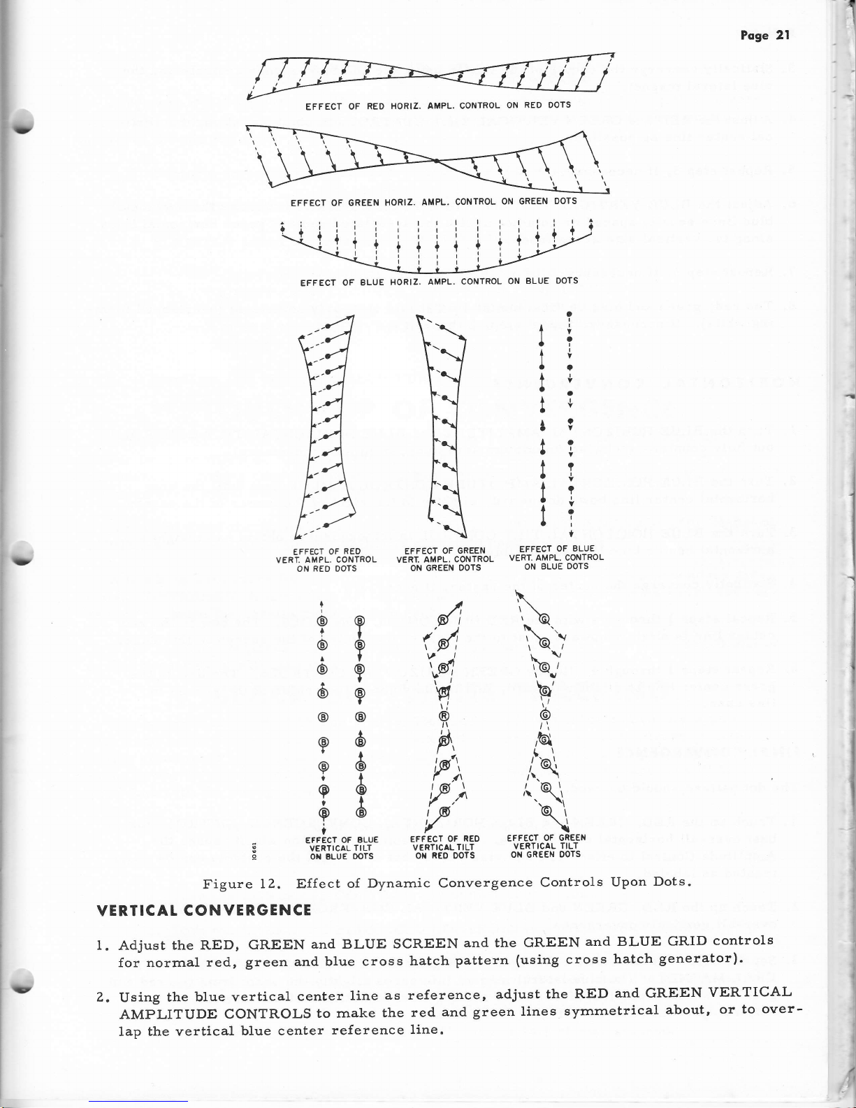
EFFECT
OF
RED
EFFECT
OF
GREEN
E-IFECT
OF BLUE
veni. ampr-.
cor,tinol veRr. aupl.
coNTRoL
vERT. AMPL. coNTRoL
ON
RED
DOTS
ON GREEN
DOTS
ON
BLUE OOTS
I
I
t
I
t
I
t
EFFECT OF
BLUE
EFFECT
OF
REO
I VERTTcAL
TILT
vERTIcALTILT
E on BLUE
oors
oN
REo
oors
Figure
12.
Effect
of Dynarnic
Convergence
Controls
Upon
Dots.
VERTICAL
CONVERGENCE
I. Adjust
the RED, GREEN
and BLUE SCREEN
and the
GREEN
and BLUE GRID
controls
for norrnal
red,
green and
blue cross
hatch
pattern
(using
cross
hatch
generator).
2.
Using
the
blue vertical
center
line
as reference,
adjust the
RED
and
GREEN
VERTICAL
AMPLITUDE CONTROLS
to rnake
the
red
and
green
lines
syrnrnetrical
about,
or
to
over-
lap the
vertical
blue center
reference
1ine.
?
?
I
I
@
6
6
6
6
I
@
i
o
I
6
6
@
\
\\o
t\
''\')
\@/
9',
6
,Gl
rl
i\
(
@.\
.\,
b\
\
EFFECT
OF GREEN
VERTICAL
TILT
ON GREEN
OOTS
{l
(ll
t,q
Y
I
A
"P'),
tf,)
f
!
1
I
i
I
l
i
i
I
i
:
I
,
I
,l
1
I
I
i
I
EFFECT
OF
RED
HORIZ. AMPL. CONTROL
ON
RED OOTS
EFFECT
OF GREEN
HORIZ.
AMPL.
CONTROL
ON GREEN
DOTS
EFFECT OF
BLUE
HORIZ.
AMPL.
CONTROL
ON
BLUE DOTS
t'
Page
22
3"
Statically converge
the
center
of the raster using
the DC convergence controls
and
the
blue
lateral
rnagnet.
4. Adjust
the RED and
GREEN
VERTICAL TILT
CONTROLS
to
obtain as
straight
a
verti-
cal center line as
possible.
5.
Repeat
step
3, if necessary.
6. Adjust
the BLUE
YERTICAL
TILT
and
AMPLiTUDE
CONTROLS
to make the
horizontal
blue lines
equally
spaced or coincident with
the
associated red and green horizontal lines
along
the vertical
axis
of the tube.
7.
Repeat
step
3,
if
necessary.
8.
The
red, green
and
blue
vertical center
line should be nearly coincident
(overlapped forrn-
ing white).
If
necessarlr
repeat
steps
2
through 7.
HORIZONTAL
CONVERGENCE
1"
TUTN thc
BLUE
HORIZONTAL
AMPLITUDE and
BLUE
HORIZONTAL TILT
CONTROLS
out
fully
counter-clockwise
(rnaxirnurn
arnplitude,
rninirnurn inductance).
2.
Turn
the BLUE
HORIZONTAL
AMPLITUDE
CONTROL in
(clockwise)
until the
blue
horizontal
center line
bows downward,
slightly
to the right of the
center of
the
screen.
3.
Turn
the
BLUE
HORIZONTAL
TILT
CONTROL in
(clockwise)
to obtain
as
straight a
horizontal
center blue line
as possible.
4" Statically
converge
the center
of
the
raster,
if necessary.
5.
Repeat steps
I through
4 with
the
RED
HORIZONTAL
CONTROLS.
The
bow in
the
red.
center line is slightly
upward,
just
to the right
of the
center of
the
screen
in this case.
6.
Repeat
steps
I through
4 with
the
GREEN
HORIZONTAL
CONTROLS. The
bow in
the
green
center
line is
slightiy
upward,
just
to the right
of the center
of the
sc:een
in
this case"
FINAT CONVERGENCE
The
dot
pattern should
be used.
1. Touch up the RED, GREEN
and BLUE
HORIZONTAL CONVERGENCE
CONTROLS
for
best over-a1l horizontal convergence. There
is some interaction
which causes
the
Arnplitude Control to
effect Tilt
and
visa
versa,
but in
general
the controls
can be
treated
as
labeled.
2.
Touch
up the
RED, GREEN
and
BLLIE VERTICAL CONVERGENCE
CONTROLS
for
best
over
-a11
vertical
convergence.
r(
t"{
3.
Set the
best
over-a11
static convergence using
the
DC
CONTROLS
and
the BLUE LAT-
ERAL
MAGNET. The blue lateral tnagnet influences slightly
the bearn
from
the
red
and
t
(
green
electron
guns,
therefore, after
rnaking
final adjustment of the blue
lateral rnag-
net, readjust
the
RED
and
GREEN
DC controls.
Poge
23
TOUCH
I
UP
OF
PURITY
A
TOUCH-Up
of PURITY
rnay
be
required
on a
new
receiver
or
following
the
conver-
gence
adjustrnents.
In
either
case,
rnake
the
following
adjustrnents
until
good
purity is
achieved
for
the
red
field.
1. Perform
steps
Z, 3
and 4
under COLOR
PURITY
on
page 15.
2. Adjust
RIM MAGNETS
for
good purity
around
edges
of
raster.
3. SLIGHTLY
adjust
the tabs
on the
PURITY
RINGS,
if
necessary.
CAUTION:
ADJUSTMENT
OF
PURITY
RINGS
WILL
UPSET
CONVERGENCE.
HOWEVER,
THE
RESULTS
OF
A VERY
SLIGHT
ADJUSTMENT
MAY
BE NEGLI-
GIBLE
UPON
CONVERGENCE
AND
MAY
IMPROVE
PURITY.
4. Perforrn
step
12 under
COLOR
PURITY.
TOUCH
-
UP
OF
CONVERGENCE
A TOUCH-Up
of CONVERGENCE
is
not arrshort-cutrrfor
correctly
adjusting
the
re-
ceiver
for convergence.
Careful
reading
of
the CONYERGENCE
procedure,
or
previous
experlence
in rnaking
convergence
adjustrnents
will
aid the
servlce
technician
to deterrnine
whlch
controls
rnight
need a slight
touch-up.
It rnay
be found
that
following
the COLOR
PURITY,
CONVERGENCE
and
TOUCH-UP
of
PURITY
adjustrnents
that CoNVERGENCE
rnay
also
need
a
touch-up.
A touch-up
procedure
for
convergence
is
(1)
to
fo1low the
step-by-step
procedure
given
under CONYERGENCE
(cornplete
set-up)
and
(2)
rnake
only
the
adjustrnents
which
are
nec-
essary
to obtain
the
results
rnentioned
in each
step.
If
the
receiver
requires
only
a
touch-up,
the
adjustrnents
under
CONVERGENCE
will
be
easier to rnake
and
will take
less time.
BLACK
ond
WHITE
TR'ACKING
The
purpose of
the BLACK
and
WHITE
TRACKING
adjustrnent
is
to
produce
a
good
black
and while
picture within
the
usable
range
o{ the
Brightness
and
Contrast
controls.
If
this
adjustrnent
is
not
properly
rnade,
a
black
and
white
picture
will
appear
tinted
with
color
as
the Brightness
or Contrast
controls
are adjusted
and a color
picture
will
be
re-
produced
with
the wrong
colors.
Tune
in a
station
that
is transrnitting
black
and white
pictures.
Make
adjustrnents
as follows:
1. Turn
the
CONTRAST
CONTROL
cornpletely
to minirnurn.
Z.
Turn the GREEN
and BLUE
GRID CONTROLS
to
extrerne
left
(rninirnurn).
3. Adjust
the RED,
GREEN
and BLUE
SCREEN
CONTROLS
to
about Ll2
rotation
clockwise.
At these
settings
the
picture
should
be
red when
the
brightness
is
turned
up.
4. Adjust the
Brightness
control
until
the
picture
is
just
extinguished.
 Loading...