

Page 1
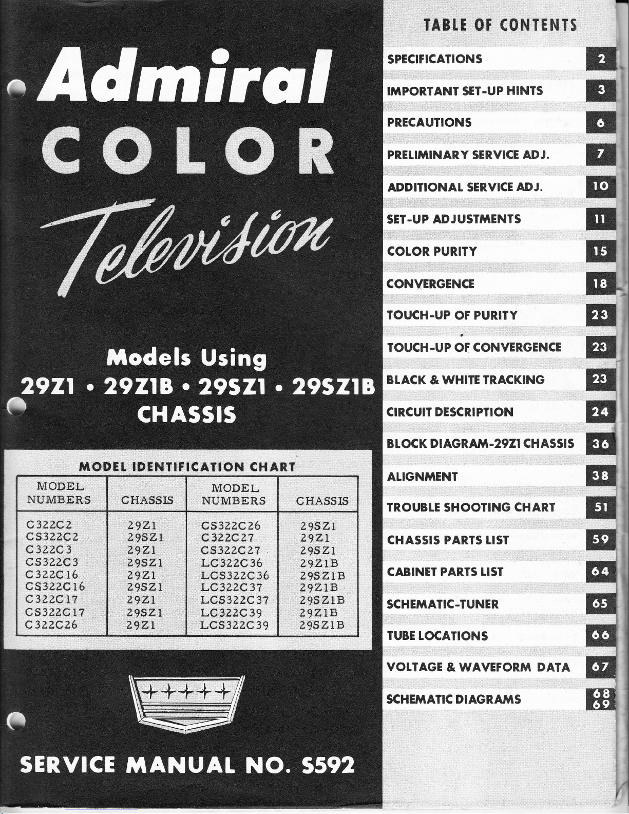
TODTL IDTNTITICAIION
CHART
MODEL
NUMBERS
CHASSI5
MODEL
NUMBERS
CHASSIS
C3ZZCz
CS3?,ZCZ
C3Z?,C3
cs3z.z.c3
C3Z?,Q16
cs322C
l6
C3ZZCTT
CSSZ?,C11
c3?.zcz6
29ZI
EgSZI
29z;,1
ZgSZI
ZgZL
Z9SZI
ZgZL
Z9SZL
Z9.ZL
QS3?,ZCZ6
C32ZCZ7
cs3zzc?7
LC3?2C36
LCs3ezc
35
LC3ZZ,C37
LCS322C37
LC3ZZC39
LQ,3ZZC39
Z9SZI
zgzr
ZgSZL
Z,9ZIB
ugszlB
ZgZLB
LgSZLB
?9ZIB
z95ZlB
TABII OT
(ONTTNTS
SPECIFICATIONS
IIITPORTANT SET.UP
HINTS
PRECAUTIONS
PRELIMINARY SER,VICE ADJ.
ADDITIONAT SERVICE
ADJ.
SET.UP
ADJUST'IIENTS
COLOR PURITY
CONVERGENCE
TOUCH.UP
OF
PURITY
TOUCH.UP OF
CONVERGENCE
BTACK
& WHITE
TRACKING
CIRCUIT DESCRIPTION
B L
OC
K
D I
AGRAIVI
.2921
CH ASSI
S
ALIGNTYTENT
TROUBLE
SHOOTING
CHAR,T
CHASSIS PARTS
LIST
CABINET
PAR.TS LIST
SCHEMATIC-TUNER
TUBE
LOCATIONS
VOLTAGE
&
WAVEFOR.frT DATA
SCHEfrTATIC DIAGRA}TS
E"
rr
rt
n,
E
r
E'
B
E
E
Iil
w
I
E
Etr
EI
E
,t
E'
ql
q1
@l
:;
BI
Page 2
Pege
2
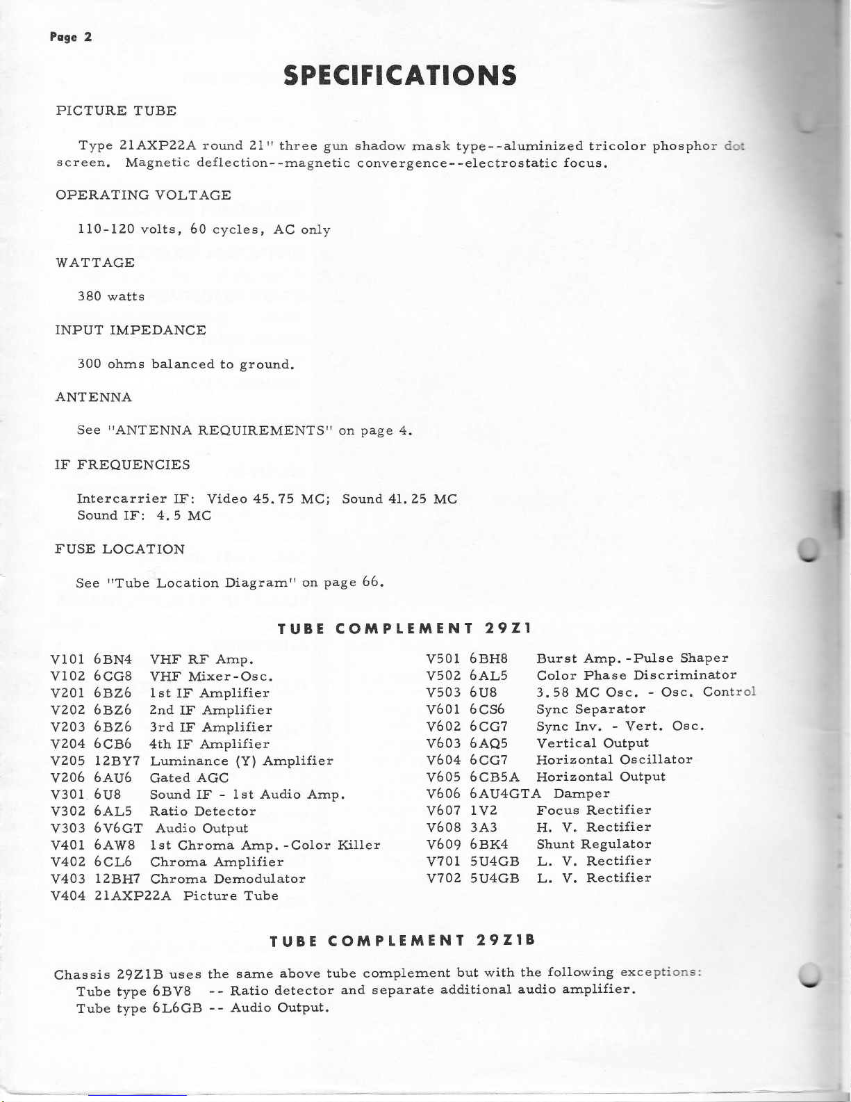
SPECIFICATIONS
PICTURE
TUBE
Type
2LAXPZZA
round
21't
three
gun
shadow
rnask type--alurninized tricolor
phosphor
screen.
Magnetic
deflection--rnagnetic
convergence--electrostatic
focus.
OPERATING VOLTAGE
110-120
volts, 60 cycles,
AC only
WATTAGE
380
watts
INPUT IMPEDANCE
300
ohrns balanced
to
ground.
ANTENNA
See
TIANTENNA
REQUIREMENTSTT on
page
4.
IF
T'REQUENCIES
Intercarrier
IF: Video
45.75
MCi
Sound. 4L.25
MC
Sound
IF:
4.5
MC
FUSE
LOCATION
See
rrTube"Location
Diagrarn'r
on
page 56.
IUBE
COiTPLEMENT
2921
vI0l
Y102
v20l
YZO2
YZo3
YZ04
vzoS
YZ06
v301
v302
v303
v401
Y402
v403
Y404
6BN4
VHf'RF
Arnp.
6CG8
VHF
Mixer-Osc.
6AZ6 tst
IF Arnplifier
5826 2nd
IF Amplifier
6826
3rd
IF Amplifier
6CB5 4th
IF Arnplifier
LZBYT
Luminance
(Y)
Arnplilier
6au6
Gated AGC
5UB
Sound IF.
-
lst Audio Arnp.
6AL5 Ratio Detector
6V6cT
Audio
Output
6AW8 lst
Chrorna
Arnp.
-Color
Killer
5CL6
Chrorna
Amplifier
LZB}IT
Chrorna
Demodulator
?LAXPZZA
Picture Tube
V501
5BH8
Burst Amp.
-Pulse
Shaper
V502
6AL5 Color
Phase
Discrirninator
V503
6U8 3.58
MC
Osc. - Osc.
Control
V601
6CS6 Sync
Separator
V602
6CG7 Sync
Inv. - Vert. Osc.
V603
6AQ5
Vertical Output
V604
6CGZ
Horizontal
Oscillator
V605
5CB5A Horizontal Output
v606
6AU4caA Damper
Y607
IYZ Focus Rectifier
V608
3A3
H. V.
Rectifier
V609
6BK4 Shunt Regulator
V701
5U4GB L. V.
Rectifier
V702 5U4GB
L. V. Rectifier
TUBE
COiTPLE}TENI
29ZIB
Chassis
Z|ZLB
uses
the
sarne
above tube cornplernent
but
with the
following
exceptions:
Tube
type 6BV8
-- Ratio
detector
and
separate
additional
audio
amplifier.
Tube
type 6L6GB
--
Audio
Output.
Page 3
Poge
3
TUBE CO}TPLEMENT
29SZI
Chassis
Z?SZL
uses the sarne
tube cornplernent as 29Zl but with
the
following addition:
Tube type
6Af'4A
--
UHF Oscillator.
TUBE
CO'IIPLEMENT
29SZIB
Chassis
Z9SZLB uses
the
sarne
tube cornplernent
as 29218
but with the
following
addition:
Tube type 6AF4A
--
UHf'
Oscillator.
IMPORTANT
COLOR R.ECEIVER SET.UP
HINTS
flM[:*,yl,,,;Ti::""x;'."",1ffi
il""i?[#"J.":?*."1?#",I]"i.ii,1x;
understanding
the lirnitations
of
present
day design will enable
you to fully acquaint
yourself
with
the
color receiver.
Tll€ll
read
the
"PRELIMINARY
sERVICE
ADJUSTMENTS"
on
pase ?,
turn
on
J
'.2t-
the
receiver, and deterrnine which
service adjustments
are necessary.
These
adjustrnents
should be rnade before the
I'COLOR
SET-UP
ADJUSTMENTS".
llufi
':"fiffi
'iJ,:";";'.'r:;J;si";Tlr;T;.i;ilTi'J1'"T';;;:'i
first read
completely,
it
will
be
easier
to
decide what
adjustrnent is necessary.
The
uprt and
[cornpletetr
procedures
are
outlined
under
this
section.
KNOW
THE
COTOR
RECEIVER
IMPORTANT:
The
following data should be read
cornpletely before rnaking
any color
set-up adjust-
ments.
I N SI A
t
L AI I O
N
RE Q U
I R E M
E
N I S
The color
receiver
should be
placed
away
frorn bright
windows or lights.
Sorne
light
in
the
roorn is desirable but should
not
fall directly on the
screen. Receiver
should
always
be
viewed
in a roorn with low
light 1eve1.
Allow
for adequate
ventilation. Receiver
should
be placed
away
frorn radiators,
heat-
ing vents, etc. Do not
place too
close
to walls.
Be
sure receiver is
conveniently
located
near electrical
outlet
and
for
antenn& conn€c-
tion.
IMPORTANCE OF DARK AREA FOR
SEI.UP ADJUST}TENIS
Since ultirnately, the
fidetity of color
reproduction
is dependent
upon
the
accuracy
of
the
convergence
and
purity
adjustrnents, these
adjustrnents
should
be
rnade
in
a darkened
room
with the receiver in the
sarne location
and
position as
used
for
viewing.
Window
shades,
venetian
blinds, etc. should be
drawn or closed to
eliminate
as rnuch
light
as
posslble.
If
enough
light
cannot
be
elirni.nated,
the color
receiver shouldg!b.
set-up
in that
area
or
roofiI. A
large cardboard carton
or cloth
shroud can
be
placed
over
the
cabinet
to
darken
set-
I
are
'rtouc}r
t
t
Page 4
Poge
4
the screen for
ease
and
accuracy in perforrning adjustrnents.
It
is preferable
that the
ad-
justments
be
rnade with the
receiver
in the location where it
will
be used.
However,
ad-
justments
rnust be
checked
and
readjusted if
necessary, with the
receiver in the final loca-
tion,
position,
and with
the sarne
light conditions under which it will be viewed.
This
is
necessary
because
of the affect
of the earthrs
rnagnetic
field
and other
external rnagnetic
fields
upon color
purity
and
convergence.
For exarnple, a color
receiver
that is
properly
adjusted
facing a particular
direction,
rnay reproduce faithful
colors. If this
receiver is
turned or
ry1!
to face in another
directlon,
purity
and
gyg.ry,
rnay
now be
out
of ad-
justrnent.
The extent
of the effect of
rnoving the
receiver after if is set
up
will
vary
from
set to set and location
to
location.
TIMITS
OF PURITY AND CONVERGENCE
Perfect
convergence
norrnally cannot be obtained over the
entire
screen
area.
Picture
tube
and deflection
yoke developrnent
of
present-day design
lirnit this condition,
but it
should be
understood that with careful and accurate
adjustrnents,
a
very
good convergence
covering at
least 85% of the screen area
can be
achieved.
Good
convergence
in
the
four
corners
of
the raster rnay
not be obtained, but if..85%
(plus
or
rninus 5%l of. the
total
area
is accurately
converged, this is considered
a norlTral, acceptable
condition.
The
present-day
color
picture
tube
also
lirnits color
purity.
I4rith
careful
and accurate
adjustments, good
color
purity
can be
achieved for
each o{ the three
fields
with
good
black
and white reproduction.
Very
smalL areas of irnpurity at any
of
the four corners 6r
sides
of the
raster are
considered
acceptable.
BTACK
AND WHlTE
TR,ACKING
The
black and
white
tracking
adjustment
is another irnportant consideration. If
properly
rnade, the
color
set
will
produce
black
and
white
pictures
within the
norrnal
useable
range
of
both lhe
Contrast
and
Brightness controls.
If
the adjustrnent i" ir,Effii,TGtiE[T.-
ture wllI appear
tinted and
the color will
vary
at
different Brightness
and
Contrast
control
s etting s
.
Cornplete
TTBLACK
AND
WHITE
TRACKING'|
instructions are contained in the
"COLOR
SET-UP
ADJUSTMENTS"
on
page
II.
DEATER
AND CUSTO}TER INSTRUCTION
The Operating Instructions
packed
with the
receiver
should be
reviewed
with all
those
who
will operate
and
use
a
color
television
set.
The expected
perforrnance
and
lirnita-
tions of the color
set should also
be explained to the
dealer
or customer.
This
will help
thern
rrunderstandrt
their color receiver.
DEMAGNETIZING IHE
COLOR
PICTURE
TUBE
Satisfactory
purity and/or
convergence
of
a
color
receiver rnay be
difficult or
irnpos-
sible
to
obtain if
the metal
parts
of the
picture
tube or chassis
have
become magnetized.
Therefore,
a dernagnetizing or degaussing
procedure should be
perforrned before making
the
Color
Set-Up Adjustrnents. Instructions
on how to make
a dernagnetizilrg
coil
are
given
under
"DEMAGNETIZING
COIL"
on
page 49.
ANTENNA
REQUIRTMENTS
The
antenna requirernents for color
reception
are rnuch rrrore
critical
than
for black
and
Y
(
Y
(
Y
Page 5
U
Poge
5
white
reception.
tr'or best
color reception,
a broad
band antenna
should be used.
It
should
also
have
an
essentially
flat frequency
response
characteristic across
the
frequency range
of
the
desired
channel.
Some antennas
of
the
'rYagitr
type
do
not rneet
these
requirernents
and should
not be
used.
Built-in
and
Indoor antennas
!o 4ot
rneet
these
requirernents
and
should
not be
used.
The
CONICAL type antenna
is a good
choice for
color
reception.
Antenna
orientation
is also
rnore
critical than for
black
and
white reception.
Sorne
an-
tenna
positions
rnay
provide
adequate black
and
wh:ite
reception,
but poor
color
reception.
If color reception
is poor,
and
the receiver is
operating
properly,
the antenna ehould be
oriented
for
best
color reception
while
receiving
a
color
program.
If
several stations are
received
frorn
different
directions, an antenna
rotator
rnay
be
required.
Multiple
antenna
installations, particularly
those
ernploying
distribution
arnplifler
sys-
terns,
rnay not provide
satisfactory
eolor reception.
Many TV
boosters do not
have
suffi-
cient
bandwidth for
color reception.
Standing
waves present
on the antenna
lead-in
can also result
in
poor
color or no color
reception.
The
lead-in
should
be
properly
rnatched
to the r"ceivurFelkninate
tffi condi-
tion.
To deterrnine
if
standing waves are present,
any
one o{
the two
following
rnethods can
be
used:
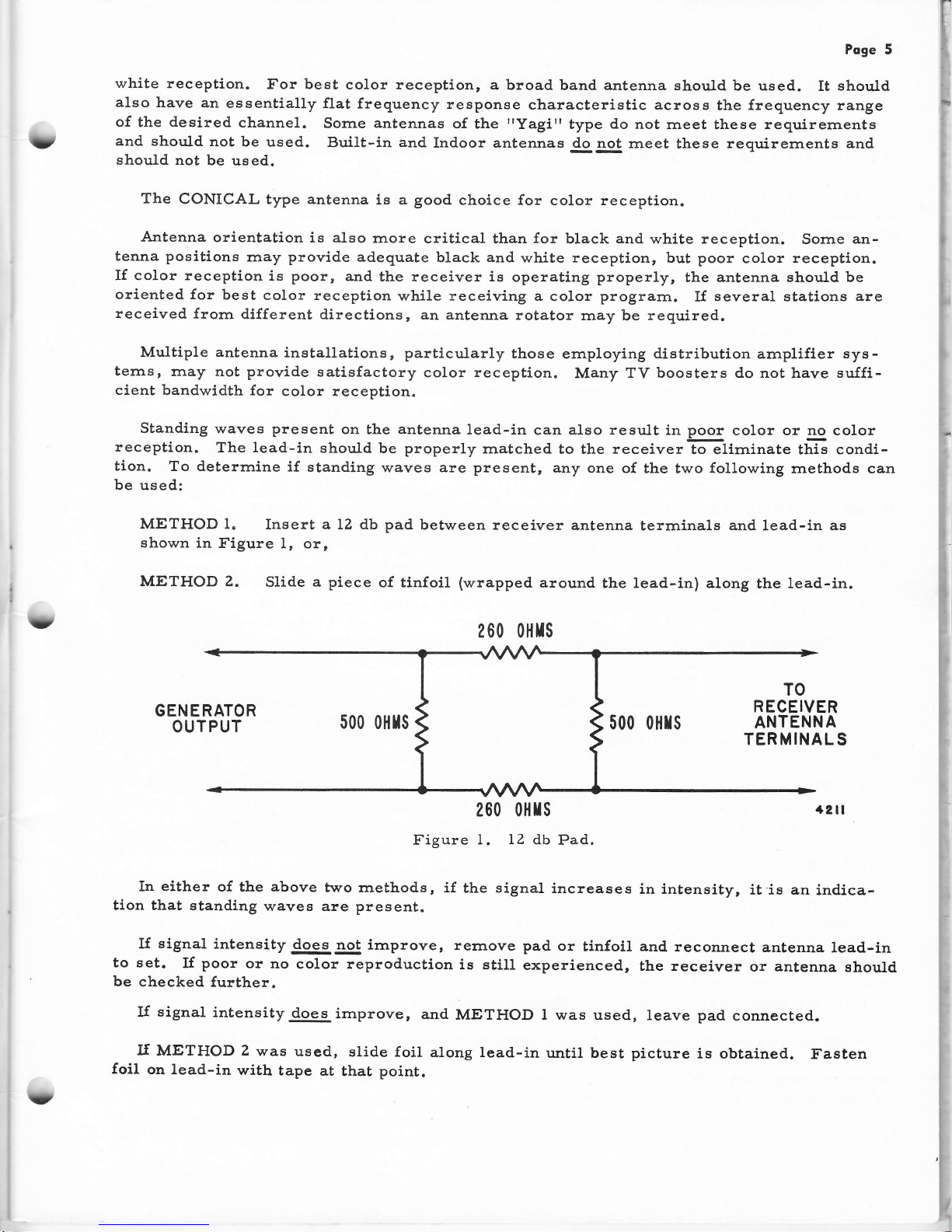
METHOD 1.
Insert a LZ db pad
between receiver
antenna
terrninals
and
lead-in
as
shown
in Figure
1, or,
METHOD 2.
Slide a piece
of tlnfoil
(wrapped
around
the lead-in) atong
the
lead-in.
260 0}lrs
t?
GENERATOR
OUTPUT
500 oHIs
500 o}lrs
TO
RECEIVER
ANTENNA
TERMINALS
+21I
200 0}lrs
Figure
1. 12 db
Pad.
In either
of the above
two rnethods,
if the signal
increases
in lntensity,
it'is an
indica-
tlon
that standing
waves are present.
lf
signal
intensity
does
not irnprove,
rernove pad
or
tinfoil and. reconnect
antenna
lead-in
to set.
I{
poor
or
no
color reproduction
is
stilI
experienced,
the receiver
or
antenna
ehould
be checked
further.
If signal
intensity
does
irnprove,
and
METHOD l was used,
leave
pad
connected.
lf
METHOD 2
was
used,
slide foil
along lead-in
until best picture
is obtained.
Fasten
foil on lead-in
with
tape
at
that
point.
U
Page 6
Poge
6
PRECAUTIONS
HANDTING
OF
CHASSIS
The
picture
tube used
in
this
chassis
is rnuch
rnore
fragile than
any black
and white
pic-
ture
tube. The
possibility
of
accidental
breakage
is increased
because
of
additional
assem-
blies mounted
on the
neck of the tube.
The
foltowing
precautions
should be taken.
t. It
is irnportant that
ehatterproof
goggles,
heavy
gloves and
a
protective apron
be
worn while handling
or
installing
a
picture
tube.
2. Do not
slide
the
assernblies
rnounted
on
the
neck of the
picture
tube
hastily
or
care-
lessly,
and
without
observing the
procedures
given.
3. Scratching,
burnping or excessive
pressure
on
the
picture
tube
can
result
in
an ex-
plosion
of considerable violence.
The
circuits of this chassis
are
more
nunierous
and cornplex than
in black
and white
re-
ceivers.
Rough or careless
handling
increases the
possibility of
accidental circuit
faiLures.
HIGH VOLTAGE
WAR,NING
Very
htgh
voltage
is
present at sorne
points in this
receiver.
The
20,000 volt
high
volt-
age
regulated supply has
sufflcient energy
to cause
severe injury
or
death.
It ls
irnperatlve that the
following high voltage
precautions
be observed.
1.
Operation
of the
set outside of the
cabinet
or with the
cabinet
back
removed
is a
po-
tentlal
shock hazard.
Z. Severe
shock
can
result
without
rnaking
physical contact
with
any
high voltage
sources.
At all
tirnes
when the
receiver
is operating,
keep
at least
3rr
away
frorn
all points
where
high
voltage
is
present.
3. This
set usea
a rnetal coned
picture
tube
that
is
protected
by a covering
insulator
(boot).
At the
front edge of
the tube
near the
rnetal-to-glass
seal
,
there
is consid-
erable
shock hazardwithln
a distance
of
approxirnately
3'r
frorn
this edge.
X.NAY WARNING
'When
the
set is operating,
the
screen
of the
picture tube
radiates
soft
X-Rays.
These
are norrnally
absorbed
in the
safety
glass front,
but
operation
of the
receiver
outside
the
cabinet
leaves the
screen
unprotected.
This
results
in
a focal
point of these
X-Rays
at
a'
bout
9r'in
front
of the
central
screen
area. Exposure
within
this
area
for more
than
l7
hours
a
week inay
cause
physical injury.
The
X-Rays
are weaker
around
the
edge
and
sldes of the tube.
Physical
exposure
time
around
this
area is unlirnited.
When
maklng
adjustrnents
with
an
r.rrprotected
picture
tube,
avold
rernaining
in the
area
directly
ln front of the
plcture tube
for
rrrore than
the
17 hours
per
week
tirne
lirnit.
If
it
becornes
necessary,
slrield the
front
of the
tube
with
plate
glass
(at
least
l/4"
thick).
Thls
will
absorb
all X-Rays
from the
front
area of the
screen.
Y
(
t(
U,(
"t
Page 7
I
t
Poge
7
PRELI'WNARY
SERVICE
ADJUSTMENTS
It is lmportant
that any
prelirninary
service adjustrnents
be
rnade before the color set-up
adjustrnents
to
prevent
upselting
color
purity
or
convergence.
Carefully check, and
if necessarlr
rnake the following
adjustrnents
in
the
order listed be-
Iow.
CHANNET
STUGS
The setting
of
the
Fine
Tuning
control
and
Channel Slugs
are
rnuch more critical
for
col-
or
reception.
Be sure
the correct
point
of tuning, as described
below, oscurs at
approxirnately
rnid-
rotation
of the Fine
Tuning control.
IMPORTANT:
If the
Channel Slug
or
Fine Tuning
control is slightly
rnisadjusted for a black and
white
prograrn,
the
picture
and
sound
rnay
still be
acceptable.
With the
same
Channel Slug
and
Fine
Tuning
control setting for a
color
prograrn,
the
picture
rnaygg!
E
t. color.
The
customer
should
be farniliarized with
the irnportance of
correctly
setting
the Fine
Tuning
control.
If
Channel Slugs
need
adjustment, proceed
as follows:
A.
Turn on set.
Allow
15
rninutes for
warrn-up.
B.
Tune
in station
and set for
norrnal picture and
sound.
C. Set Fine
Tuning control at approxirnately
rnid-rotation.
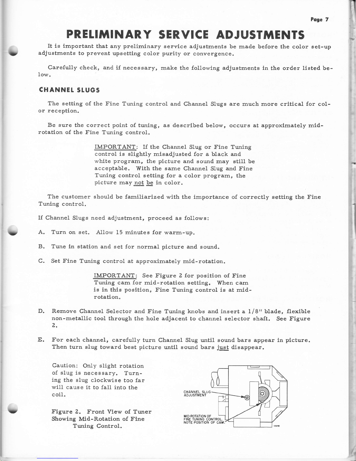
IMPORTANT:
See f
igure 2 for position
of
Fine
Tuning
carn for
rnid-rotatlon
setting.
When
carn
is
in thls
posltLon,
Fine Tuning control is at rnid-
rotation.
D.
Rernove
Channel Selector and
Fine Tuning knobs
and
insert a Lf
8"
blade,
flexlble
non-rnetallic
tool through
the hole
adjacent
to channel
selector shaft.
See f
igure
z,
E.
For
each channel, carefully
turn
Channel SIug until
sound bars appear
in
plcture.
Then
turn
slug
toward best
picture
until
sound bars
just
disappear.
Caution:
Only
slight
rotation
of
slug
is
necessary.
Turn-
ing
the slug
clockwise
too far
will
cause
it to fall into
the
coil.
Figure 2.
Front
View
of
Tuner
Showing
Mid-Rotation
of
Fine
Tuning Control.
f
?
CHANNEL SLUG
ADJUSTMENT
t1
Page 8
Pege
8
HORIZONTAL SNYC
The
picture should rern,ain
in sync throughout the
range
of the
Horlzontal
Hold
control,
even
when interrupting the signal
by switching on and off station. See Figure
3 for
location
of
Horizontal
frequency
control.
The
HORIZONTAL SYNC
adjustrnent is
per{orrned the sarne way
as
on
a black
and
white
receiver
using the rnultivibrator
and discriminator
rnethod
for
horlzontal
sync
and
sweep.
For
exarnple,
all
20Y4 series
black and white
receivers use this rnethod.
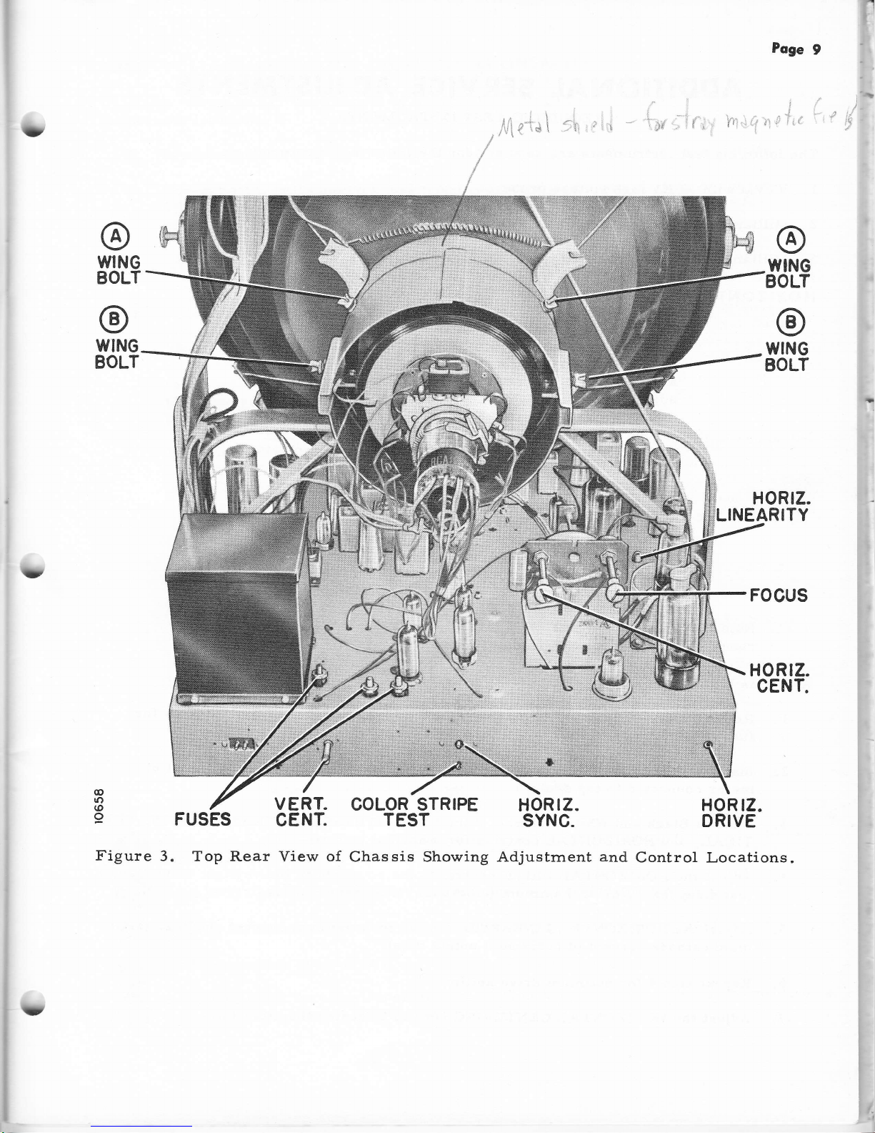
RASTER TItT ADJUST}IENT
If
raster is tilted, loosen the
@g
wing
bolts
(A) (see
Figure 3)
and rotate
yoke until
picture
is straight.
Tighten the
wing bo1ts.
Note:
tr'igure 3
shows
the
location of only
two wing
bolts
(A).
The third
is located on
the sarrre bracket
directly
underneath the
picture
tube
neck.
HEIGHI
AND LINEARITY
These
adjustrnents
are
adjusted
the
sarne way on the color
receiver
as
on
a black
and
whlte
receiver.
Be
sure to adjust for best
height and linearity
with the
picture
set at
ap-
proxirnately
llZt' beyond
the top
and bottorn lirnits
of
the
rnask. The HEIGHT
and
LINEAR-
ITY controls
are located behind
the
rernovable
panel
under
the
safety
glass frarne.
Re-
rrrove
the
four
screws frorn
under
bottorn edge of the
panel.
Panel
can then
be
easily
re-
rnoved.
Adjusting
HEIGHT
and
LINEARITY
after
color
set-up
adjustrnents rnay upset
color
purity and
convergence.
Flowever,
if only
a
slight touch-up
is
necessary
following color
set-up
adjustrnents,
the
effectEy
be negligible.
HOR!ZONTAt DRIVE
Adjust
the
HORIZONTAL DRIVE
control to a
point
where the
white vertical
line(s)
just
disappear, or
to
rna><irnurn if drive lines
do not appear. See Figure
3 for control
location.
Ma<irnurn
drive is at
rnaxirnurn
(cornpletely
clockwise)
rotation
of the control.
HORIZONTAL
AND VERTICAL CENTER.ING
Adjust
for
proper
horizontal and
vertical centering.
See
Figure 3
for control
locations.
(
(
Page 9
l}
rll,
WNG
BOLT
Poge
9
TYING
tsOLT
@
WING
BOLT
HORTZ.
NEARITY
FOCUS
@
WING
BOLT
.t
,1,:.:
trt'tj:i!,li:il:!ll:a,,irj:
:.-:::::-:ra:::ri:!i:,.4
j
c;!r'
:i
r'i:l:ii.lli:i:lef
!iia:i:l::;!:.
':.:.r
:;r :r:.:ii.r:!t1t1{1ij:
rii:
!,-:i:,i.:rirrielr::r!$;1r.
:iu:1i!i;1iiN.,:;!:.45;d
ffi"}
..'r
E#Sl
.',
lrr:i;;l.,:t;I::tti:::i;i:ti:
rt:tr
i:da!ii!i:!iii:::j:i!r
ti;;l:t
i
HORTZ.
CENT.
@
tO
@
9
FUSES
Figure
3. Top
Rear View
of
COLOR STRIPE
TEST
Chas
sis
Showing
VERT.
CENT.
HOR
rZ.
SYNC.
HOR
rZ.
DR!VE
Adjustrnent
and
Control Locations.
:
Page 10
Poge
l0
ADDITIONAL
SERVICE
ADJUSTMENTS
REQUIRING
TEST
INSTRUMENTS
The
{ollowing
test
lnstrurnents
are
required
for the
1. VTVM
with
30
KV
high
voltage
probe'
Z. Milllarnrneter
(0
-
I
rna
range).
3. Milliarnrneter
(0-500
rna
range).
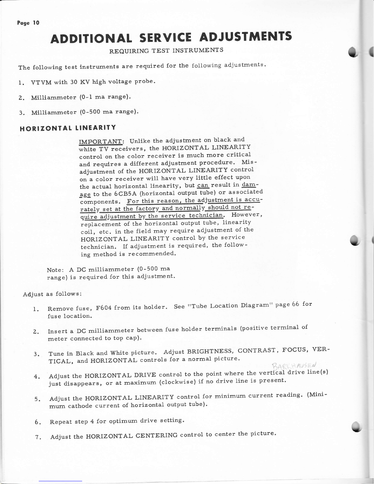
HORIZONTAL
TINEARITY
following
adjustments.
Hfi
ffi
:,,""1::";:"#*E'ff;:'rJiHxili,
controlonthecolorreceiverisrnuchrnorecritical
and
requlres
a different
adjustment
procedure'
Mis-
adjustrnent
of the
HoRIzoNTAL
LINEARITY
control
onacolorreceiverwillhaveverylittleeffectupon
the
actual
horizontal
llnearity,
but
can
result
i'44-
ggg to
the
6CB5A
(horizontal
output
tube)
or
associated
colrpon"nt".
For
this
reason,
the
adjustnle-nt
iF
accu-
.rtuiy@v@]Jv
should
not
re-
iffim'ffi,,IjriJ"''
.oiI
,
"t..
in the
field
rnay
require
adjustment
of
the
HORIZONTAL
LINEARITY
control
by
the
service
technician.
If
adjustment
is
required'
the
follow-
ing method
is
recomrnended'
Note:
A
DC milliarnmeter
(0-500 ma
range)
is
required
for this
adjustrnent'
Adjust
as
follows:
l. Rernove
fuse,
F604
frorn
its
holder.
See
"Tube
Location
Diagrarnil
page 66
for
fuse
location.
z. Insert
a
Dc
rnilliarnrneter
between
fuse
holder
terrninals
(positive
terrninal
of
rneLer
connected
to
toP
caP)'
3.
Tune
in Black
and white
picture.
Adjust
BRIGHTNESS,
CoNTRAST'
FOCUS'
vER-
TICAL,
and
HORIZONTAL
controls
for
a norrnal
picture'
i
,,
:.-
4.
Adjust
the HoRIZoNTAL
DRIVE
control
to
the
point
where
the
vertical
drive
line(s)
justdisappears,oratrnaxirnum(clockwise)ifnodrivelineispresent.
5.
Adjust
the HoRIZoNTAL
LINEARITY
control
for
minimurrl
current
reading'
(Mini-
rnurn
cathode
current
of
horizontal
output
tube)'
Repeat
step
4
for optirnurn
drive
setting'
AdjusttheHORIZoNTALCENTERINGcontroltocenterthepicture.
{
6.
U
Page 11

T
il
i
;
r
I
Poge
I I
HIGH
VOLIAGE
REGUTATOR.
HORIZONTAL
LINEAR'ITY
A
line
voltage
of I 1?
volts
should
be
rnaintained
during
this
adjustrnent.
See
Figure
3
for
adjustrnent
locations .
?
Caution:
Milliarnmeter
leads
will
be at B
p}us
potential
(380
volts).
Be
sure
to
isolate
rneter
frorn chassis'
10.
Readjust
the HoRIZONTAL
LiNEARITY
coil
in the
direction
o{
less
inductance,
(slug
moving
outward
frorn coil)
until
the
cathode
current
of the
Horizontal
Output
tube
is
approxirnately
200
rnilliamperes.
Do
not
exceed
210 rnilliarnpeles
as
lin-
earity
is disrupted
above
this
value
of current.
The
High
voltage
should
read
in
the
range
o{
tg.5
to
ZL.5 KV,
with
regulator
current
of
750
to
I000
microamperes'
optirnurn
setting
is
200
rnilliarnperes
output
tube
current
with
20 KV
high
voltage
and
regulator
current
of
950
rnicroamperes'
For
line
voltages
between
105
and 11?
votts,
adjust
HORIZONTAL
LINEARITY
control
accordingly.
For
exarnple,
aline
voltage
of
110
volts
results
in
a
ratio
of
I10
llLT
or.9i
(r"irrg
117 volts
as standard).
Therefore,
the
high
voltage
would
be
set
at.
.g4
x
20,000
volts
or
18,800
volts.
Maxirnurn
Horizontal
Output
tube
cur-
rent
becornes
.94
x 210 rnilliarnperes
or 19?
rnilliarrrperes
and rninirnurn
optirnurn
regulator
current .94
x 750 rnicroarnperes'
Rernove
rneters
and
replace
test
jurnper
wire
and
fuse'
Repeat
steps
4
andT
if'
necessary.
overscan
should
be
approxirnately
I
Ll4
inch
each
side"
Il.
Recheck
vertical
height
and
linearity.
Overscan
should
be
at least
LIZ
incln
at top
and bottorn.
8. Set
the BRIGHTNESS
and
CONTRAST
9.
Connect
a
DC
rnilliarnrneter
(0-1
rna)
6FK4
regulator
tube
(positive
lead to
.rneter
insertion.
IMPORTANT:
Before
adjustrnents
(Purity or
you have.
controls
to minirnurn,
(
for bearn
cutoff).
in
series
with the
cathode
(Pin
#i)
of the
cathode).
A test
jumper
is
provided
for
rl7
o
@
o
@
o
COLOR.
sET
-
UP
ADJUSTMENTS
rnaking
any
color
set-uP
Convergence)
be
sure
read
page
3,
"IMPORTANT
COLOR
SET-UP
HINTS",
and
followed
through
with
the
instructions,
checked
and rnade
any necessary
prelirninary
service
adjustrnents,
checked
the
receiver
f6r
perforrnance
after the
prelirninary
service
adjustrnents,
read
this
section
cornPletelY,
decided
whether
the
color
receiver
needs
a
rttouch-up"
of
so ne color
adjustrnents
or
a
ncornpleterr
color
set-up
adjustrnent'
U
Page 12
Poge
12
A
"cornplete'r
color
set-up
adjustrnent
consists
of the
following
steps
in
the order
given.
I
CENTER
STATIC
CONVERGENCE
(DC).
See Figure
lr.
II
COLOR
PURITY
III
CONVERGENCE
IV
TOUCH-UP
OF PURITY
V
TOUCH-UP
OF
CONVERGENCE
I
VI BLACK
AND
WHITE
TRACKING
(Good
black
of
the
Brightness
control)
If the
receiver
requires
a
trcornpleterl
set-up
adjustment,
rnake
all
adjustrnents
listed,
including
the
'rtouch-up'r
adjust-
rnents
"
If the
receiver
requires
only
a
rrtouch-up"
of sorne
color
adjustrnents,
rnake
those
adjustrnents
only.
Check
the
{ollowing
parts
for
cor-
rect
positioning.
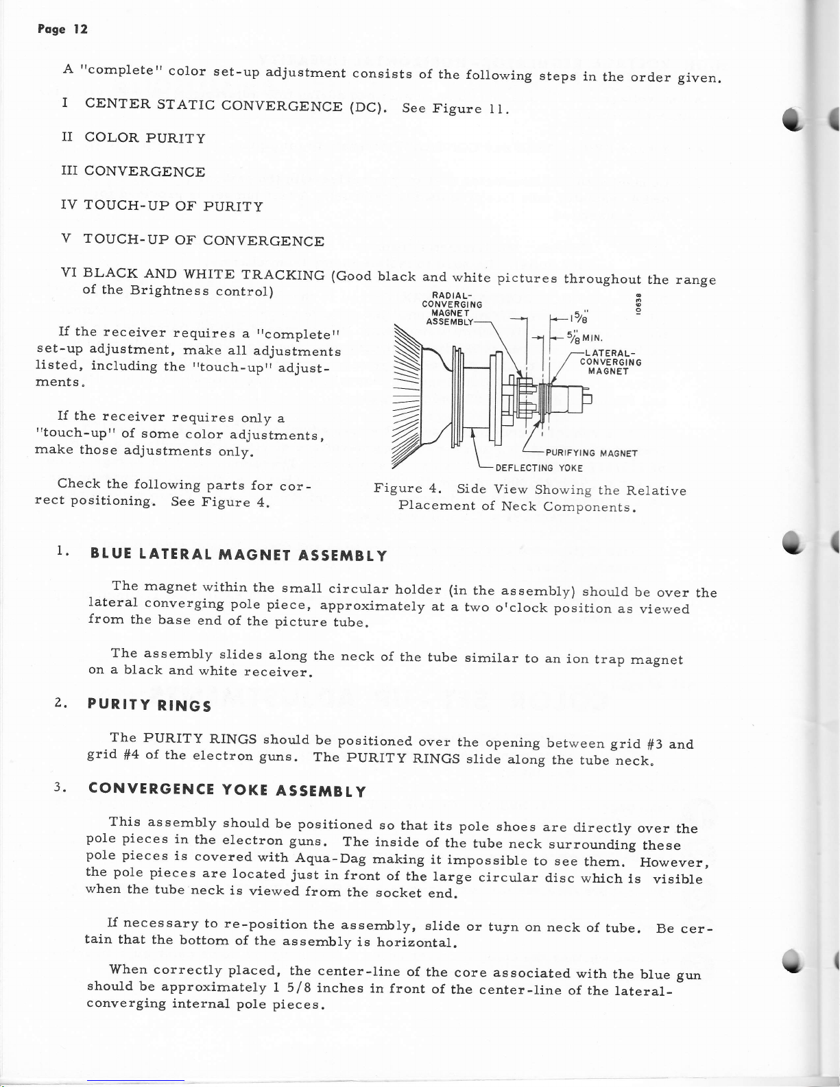
See
Figure
4.
ASSEMBLY
PURIFYING
MAGNET
DEFLECTTNG YOKE
Figure
4.
Si.de
View
Showing
the
Relative
Placernent
o{
Neck Cornponents.
and
white
RADIAL-
CONVER6ING
MAGNE T
hout
9
RAL-
;RGING
NET
the range
I
I.
z.
BtUE
TATERAL
MAGNET
ASSETIBtY
The
rnagnet
within
the
sma1l
circular
holder
(in
the assernbly)
should
be
over
the
lateral
converging
pole
piece,
approximately
at
a
two
orclock
position
as
viewed
from
the
base
end
of
the
picture
tube.
The assernbly
stides
along
the
neck
of the
tube
sirnilar
to an
ion
trap
rnagnet
on
a
black
and
white
receiver.
PURITY
RINGS
The
PURITY
RINGS
should
be positioned
grid
ff4
of
the
electron
guns.
The
pURITy
CONVERGENCE
YOKE
ASSE'ITBtY
over
the opening
between
grid
f3
and
RINGS
slide
along
the
tube
neck.
This
assernbly
should
be positioned
so
that
its pole
shoes
are
directly
over
the
pole
pieces
in
the
electron
guns.
The
inside
of
the
tube neck
surrounding
these
pole
pieces
is
covered
with
Aqua-Dag
rnaking
it
irnpossible
to see
thern.
However,
the pole
pieces
are
located
just
in front
of
thl
targe
circuLar
disc
which
is
visible
when
the
tube
neck
is
viewed
frorn
the socket
end.
If necessary
to
re-position
the assembly,
slid.e
or
tu3:n
on neck
of
tube.
Be cer-
tain
that
the
bottorn
of
the
assernbly
is
horizontal.
'When
correctly
placed,
the center-line
of the
core associated
with
the
blue
gun
should
be
approximately
I 5/8
inches
in front
of
the center-line
of the
lateral-
converging
internal
pole
pieces.
u
Page 13
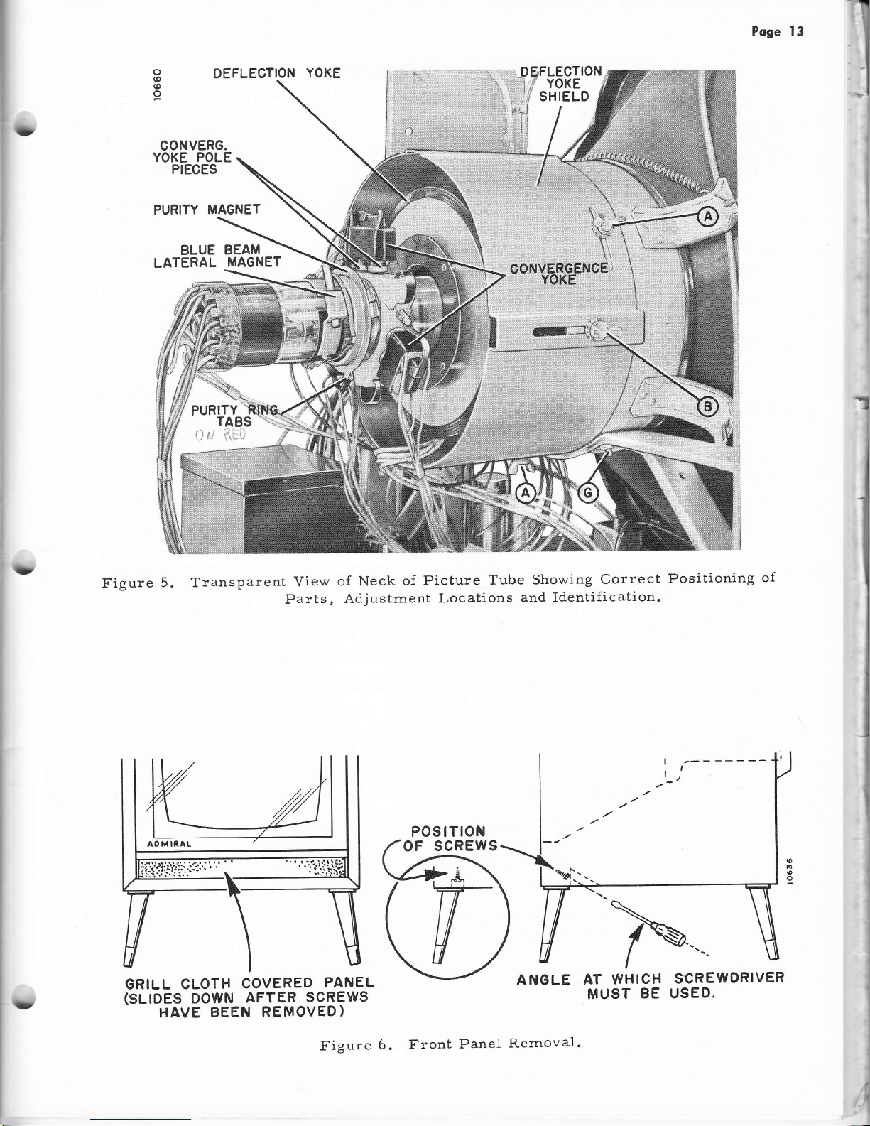
Poge 13
DEFLECTION
YOKE
CONVERG.
YOKE POLE
PIECES
PURITY MAGNET
BLUE
BEAM
LATERAL
MAGNET
/:.
-1
&
tla
Figure
5. Transparent
View
of
Neck
of Picture
Tube
Showing
Correct
Positioning
of
Parts,
Adjustrnent
Locations
and
Identification.
o
(o
(o
o
D
t
'1
i
I
I
I
GRILL
CLOTH
COVERED
PANEL
(SLIOES
DOWN
AFTER
SCREWS
HAVE
BEEN
REMOVED)
ANGLE
AT
WHICH
MUST
BE
SCREWDRIVER
USED.
ru
POSTTTON
OF
SCREWS
rD
Figure
6. Front
Panel
Rernoval
.
Page 14
Poge
14
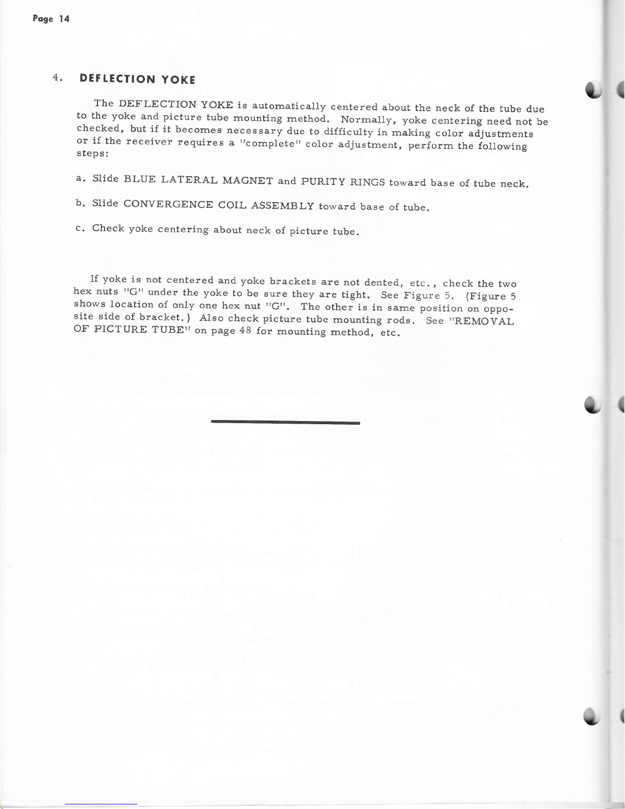
4.
DEF
TECTION
YOKE
The
DEFLECTION
YOKE is
autornatically
centered
about
the neck
of
the
tube
d.ue
to
the yoke
and
picture
tube
rnounting
rnethod.
Norrnally, yoke
centering
need
not
be
checked,
but
if
it
becornes
necessary
due
to difficulty
in
rnaking
color
adjustrnents
or if
the receiver
requires
aricornpleterrcolor
adjustrnent,
perforrn
the following
steps:
a'
Slide
BLUE
LATERAL
MAGNET
and
PURITY
RINGS toward
base
of
tube neck.
b.
slide
CONVERGENCE
coIL
ASSEMBLy
toward
base
of
tube.
c.
Check
yoke
centering
about
neck
of picture
tube.
lf
yoke
is
not
centered.
and
yoke
brackets
are
not
dented,
etc.,
check
the two
hex
nuts
"G'r
under
the yoke
to be
sure
they
are
tight.
see
Figure 5.
(Figure
5
shows
location
of
only
one
hex
nut
,Gtr.
The
other
is
in sarne
position
on oppo-
site
side
of
bracket.
)
AIso
check picture
tube
mounting
rods.
See
,REMO1;AL
OF PICTURE
TUBETT
on
page
48
{or
rnounting
rnethod,
etc.
Page 15
I
1
{
Poge
15
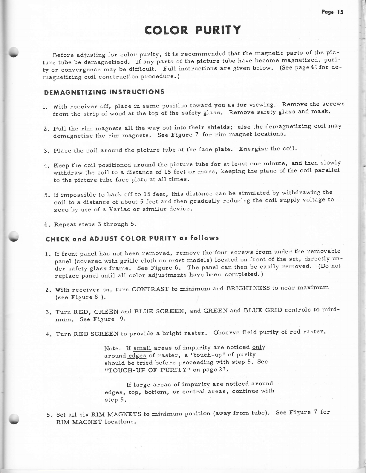
COTOR
PURITY
Before
adjusting
for
color
purity,
it is
recomrnended
that
the
magnetlc
parts
of the
pic-
ture
tube
be
dernagnetized..
If
any
parts
of the
picture tube
have
become
rnagnetized,
puri-
ty
or conv.rgurr".
rrray
be
difficult.
FuII
instructions
are
given below.
(See
page49f'or
de'
rnagnetizing
coil
construction
procedure.
)
DEMAGNETI
ZING
IN
SIR
UCIIONS
I. With
receiver
off
,
place in
sarne
position
toward
you
as for
viewing.
Rernove
the
screws
from the
strip
of wood
at the
top
of the
safety
gIass. Rernove
safety
glass
and rnask'
Z.
pull
lhe
rirn rnagnets
all
the
way
out
into their
shields;
else
the
dernagnetizing
coil
rnay
dernagnetize
tirre
rirn
rnagnets"
See
I'igure
?
for
rirn
rnagnet
locations.
3. Place
the
coil
around
the
picture tube
at
the
face
plate.
Energize
the
coil'
4.
Keep
the
coil
positioned around
the
picture tube
for
at least
one rninute,
and then
slowly
withdraw
the coil
to
a distance
of 15
feet or rnore,
keeping
the
plane of the
coil
parallel
to the
picture
tube
{ace
plate
at all times.
5.
If
irnpossible
to
back off
to 15
feet, this
distance
can
be simulated
by withdrawing
the
coil
to
a
distance of
about
5
feet
and then
gradually
reducing
the
coil
supply
voltage
to
zero
by use of
a
Variac
or
sirnilar
device.
6. Repeat
steps
3
through
5.
CHECK
ond
ADJUSI
COtOR.
PURIf
Y
os
follows
I. If
{ront
panel
has
not been
rernoved,
rernove
the
four
screws
frorn under
the
rernovable
panel
(covered with
grille
cloth
on rnost
rnodels)
located
on
front of the
set,
directly
un-
der
safety
glass
frarne.
See Figure
6.
The
panel can
then
be easily
rernoved'
(Do
not
replace
panel until
all color
adjustrnents
have
been
cornpleted.
)
Z.
With
receiver
on, turn
CONTRAST
to rninirnurn
and BRIGHTNESS
to
near
rnaxirnurn
(see
Figure
8
).
3. Turn
RED, GREEN
and BLUE
SCREEN,
and
GREEN
and BLUE
GRID
controls
to
rnini-
rnum.
See
Figure
9-
4. Turn
RED
SCREEN
to
provide
a bright
raster.
Observe
field
purity of
red
raster.
Note:
If
@lI
areas
of irnpurity
are
noticed
only
around-4gSg
of
raster,
a
rrtouch-up"
of
purity
should
be tried
before
proceeding
with
step 5.
See
"TOUCH-UP
OF
PURITY"
on
Page
23.
If
large
areas
of
irnpurity
are noticed
around
edges,
topr
bottorn,
or
central
areas,
continue
with
step 5.
5. Set
alt
six RIM MAGNETS
to
rninirnurn
posltion
(away
frorn
tube).
See
Figure
7
for
RIM MAGNET
locatlons.
3
?
U
Page 16
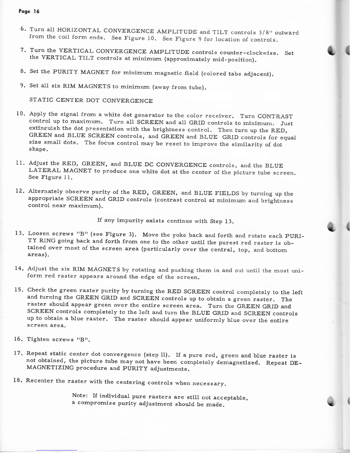
6.
Poge
15
Turn
all
HORIZONTAL
CONVERGENCE
frorn
the
coil
form
end.s.
See
Figure
I0.
7'
Turn
the
YERTICAL
CONVERGENCE
AMPLITUDE
controls
counter-clockwise.
Set
the
VERTICAL
TILT
controls
at
rninirnurn
(approxirnately
rnid-position).
8' Set
the
PURITY
MAGNET
for
minimurn
magnetic
field (colored
tabs adjacent).
9.
set all
six
RIM
MAGNETS
to rninimurn
(away
frorn
tube).
STATIC
CENTER
DOT
CONVERGENCE
t1.
App1y
the signal
frorn
a
white
dot
generator
to
the
color receiver.
Turn
CONTRAST
control
up
to
rnaximurn.
Turn all
SCREEN
and all
GRID
controls
to
rninirnurn"
Just
extinsuish
the dot
presentatlon
with
the
brightness
control.
Then
turn up
the
RED,
GREEN
and
BLUE
SCREEN
controls,
and
GREEN
and
BLUE
GRID
controls
for
equal
size
small
dots-
The focus
control
rnay
be
reset
to irnprove
the sirnilarity
of
dot
shape.
Adjust
the
RED,
GREEN,
and
BLUE
Dc
CONVERGENCE
controls,
and
the
BLUE
LATERAL
MAGNET
to
produce
one
white
dot
at
the
center
of
the
picture
tube screen.
See Figure
I
1.
AMPLITUDE
and
TILT controls
3/8"
outward
See
figure
9
for
location
of controls.
turning
up
the
and
brightness
(
10.
lz.
13.
14.
15.
Alternately
observe
purity
of the
RED,
GREEN, and
BLUE
FIELDS
by
appropriate
SCREEN
and
GRID
controls (contrast
conlrol
at
rninirnum
control
near
rnaxirnurn).
If
any
hnpurity
exists
continue
with
Step
13.
Loosen
screws
IBrr(see
Figure
3).
Move
the yoke
back
and
forth and
rotate
each
pURI-
TY
RING going
back
and
forth
frorn
one
to the
other
until
the
purest
red.
raster
is
ob-
tained
over
most
of
the
screen
area
(particularly
over
the
central
,
top, and
bottorn
areas
).
Adjust
the
six
RIM
MAGNETS
by
rotating
and
pushing
thern in and
out until
the rnost uni-
forrn
red
raster
appears
around
the
edge
of the
screen.
Check the green
raster
purity
by
turning
the
RED
SCREEN
control
cornpletely
to
the left
and
turning
the
GREEN
GRID and
SCREEN
controls
up to
obtain a green
raster.
The
raster
should
appear
green
over
the
entire
screen
area.
Turn
the
GREEN
GRID
and
SCREEN
controls
cornpletely
to the
left and
turn
the
BLUE
GRID
and
SCREEN
controls
up
to
obtain a
blue raster.
The raster
should
appear
uniforrnly
blue over
the
entire
screen
area.
16.
Tighten
screws
rrBrr.
17.
Repeat static
center
dot
convergence
(step11).
Ifapure
red,
green
andblue
raster
is
not
obtained,
the picture
tube
rnay
not
have
been
cornpletely
demagnetized.
Repeat
DE-
MAGNETIZING
procedure
and
pURITy
adjustments.
18.
Recenter
the
raster
with
the
centering
controls
when
necessary.
(
Note:
If individual
pure
rasters
are
still
not
acceptable,
a
cornprornise
purity
adjustrnent
should
be
rnad.e.
(
Page 17
(}
?
TUNER
MOUNTING
BRACKET
ANTENNA
TERMINALS
RETAIN!NG
RODS
CONVERGENCE
YOKE
PLUG
&
SOCKET
GROUND
SPRING
RIM MAGNET
Poge
17
NUT
PLASTIC
BOOT
RETAIN
ING
ROD
NUTS
RIM
MAGNETS
SPEAKER
SOCKET
HIGH
VOLTAGE
INTERLOCK
(
MOUNTED
BEHIND
SAFETY
GLASS.
)
o,
rO
(o
o
?'.['..ttJl?,[
&
SOCKECT
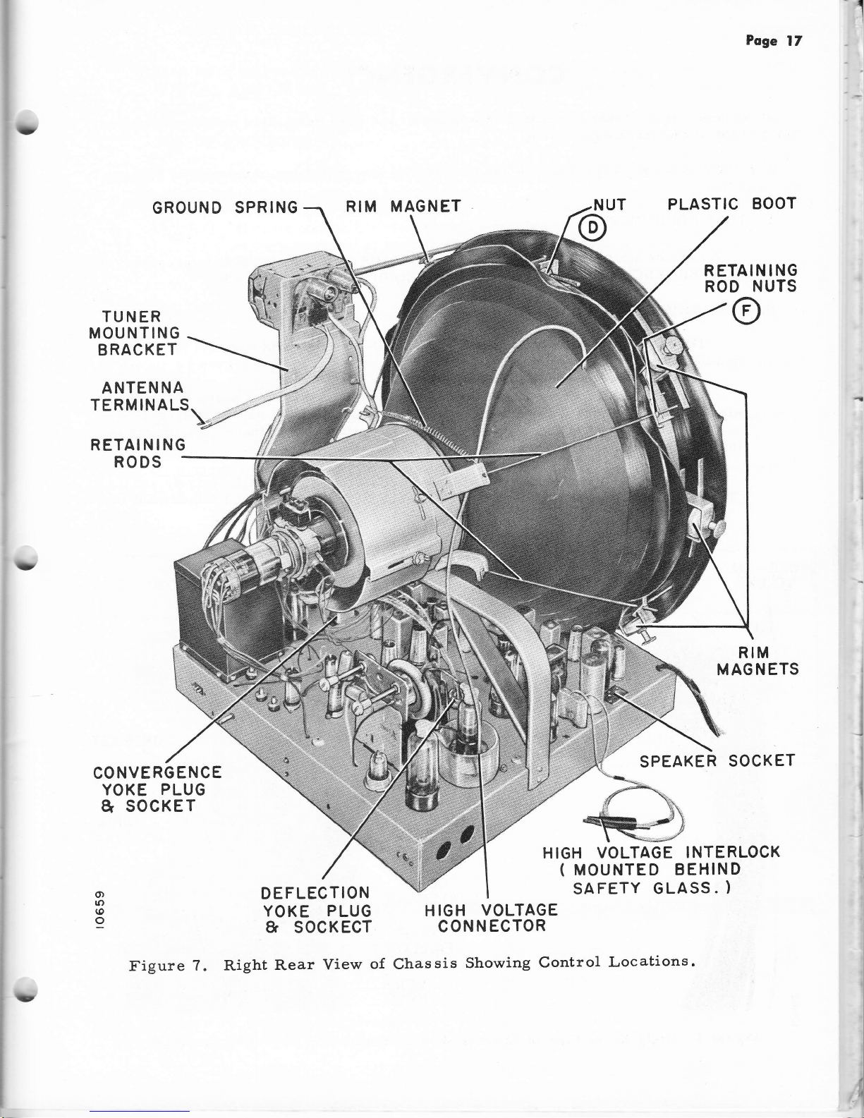
Figure
7. Right
Rear
View
o{
H
IGH
VOLTAGE
CONN
ECTOR
Chassis
Showing
Control
Locations.
Page 18

Poge
18
CONVERGENCE
convergence
is
necessary
so
that
the
Red,
Green and
Blue
Bearns
are
rnuch
of
the
screen
area
as possible.
converged
over
as
In
general,
very good
convergence
can
be
achieved
over
screen
area.
A.
TEST
EQUIPMENT
85fl0
(plus
or
minus
5a/o)
of.
t]ne
A suitable
W'hite
Dot
Generator (such
as
ADMIRAL
Model
TE-100)
is
necessary
for
CONVERGENCE
adjustrnents.
See
',TEST
EQUIpMENT,,
on
page
3g.
B.
LOCATION
OF CONTROLS
The
STATIC
Convergence
controls
are
located
on
the
fronl
apron
of the
chassis
and
the
Blue
Lateral Magnet in
its
holder
on
the
tube neck.
See Figure
5.
The
DYNAMIC
Convergence
controls
are
located
on the front
apron
of
the chas-
sis.
Rernove
the four
screws frorn
under
the rernovable
front panel
for
access
to
controls.
The panel
is
then
easily
rernoved.
Identification
of
these adjustrnents
is
indicated
in Figure 9
and
on
a
label
on the chassis
apron.
ThC Effects
o{
the
HORIZONTAL
and
VERTICAL
AMPLITUDE
controls
and
TILT
controls
are indicated
in
Figure
12.
The
HORIZONTAL
TILT adjustrnent
for
I
(
OFF-ON
VOLUME
BRIGHTNESS
CHANNEL
SELEGTOR
CONTRAST
TONE
HORtZ.
HOLD
COLOR
INTENSITY
COLOR
FIOELITY
VERT.
HOLD
(
Figure
8.
Right
Front
Yiew of
Chassis
Showing
Location of
Operating
Controls"
L
Page 19
?
lU
Poge
19
each color
will
cause
the
peaks
of
the
horizontal
waveforrn,
forrned
when
the HORI-
ZONTAL
AMPLITUDE
controls
are
advanced
fu1ly
to the
right, to
rnove
frorn
side
to
side.
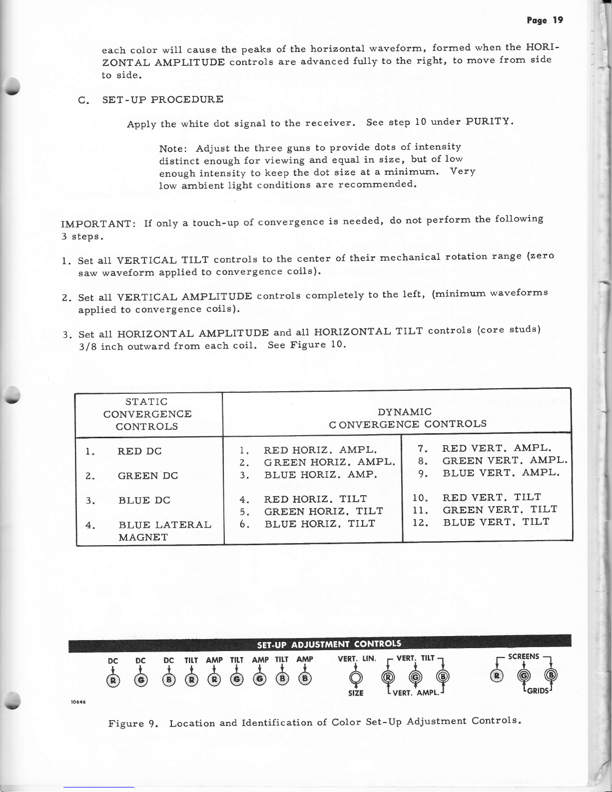
C.
SET-UP
PROCEDURE
Apply
the
white
d.ot signal
to the
receiver.
See
step
10 under
PURITY.
Note:
Adjust
the three
guns to
provide
dots
of
intensity
d.istinct enough
for viewing
and equal
in
size, but
of
low
enough
intensity
to
keep the
dot size
at a rninirnurn.
Very
low
ambient
light
conditions
are recomrnended.
iMPORTANT:
If
only
a
touch-up
of
convergence
is
needed,
do
not
perforrn
the
following
3
steps.
1. Set
all
VERTICAL
TILT
controls
to
the
center
of their
rnechanical
rotation
range
(zero
saw waveform
applied
to
convergence
coils).
Z.
Set
all VERTICAL
AMPLITUDE
controls
cornpletely
to the
1eft,
(minirnurn
waveforms
applied
to
convergence
coils).
3.
SEt
A11
HORIZONTAL
AMPLITUDE
ANd
A11
HORIZONTAL
TILT
CONtTO1S
(COTE
StUdS)
3/8
inch
oulward
frorn
each
coil.
See
Figure
10'
STATIC
CONVERGENCE
CONTROLS
DYNAMIC
C ONVERGENCE
CONTROLS
1. RED
DC
Z.
GREEN
DC
3. BLUE
DC
4. BLUE
LATERAL
MAGNET
1
Z
3
4
5
6
RED HORIZ.
AMPL.
GREEN
HORIZ.
AMPL.
BLUE HORIZ.
AMP.
RED
HORIZ.
TTLT
GREEN
HORIZ.
TILT
BLUE HORIZ.
TILT
8
9
RED
VERT.
AMPL.
GREEN
VERT.
AMPL.
BLUE VERT.
AMPL.
10" RED YERT.
TILT
I1. GREEN
VERT.
TILT
LZ.
BLUE
VERT.
TILT
E
b
d l$
,b,5
d
H H
-hj'.
$:3::A
6"Q]$
(D
Figure
9.
Location
and
Identification
of
Color
Set-Up
Adjustrnent
Controls'
Page 20
Poge
20
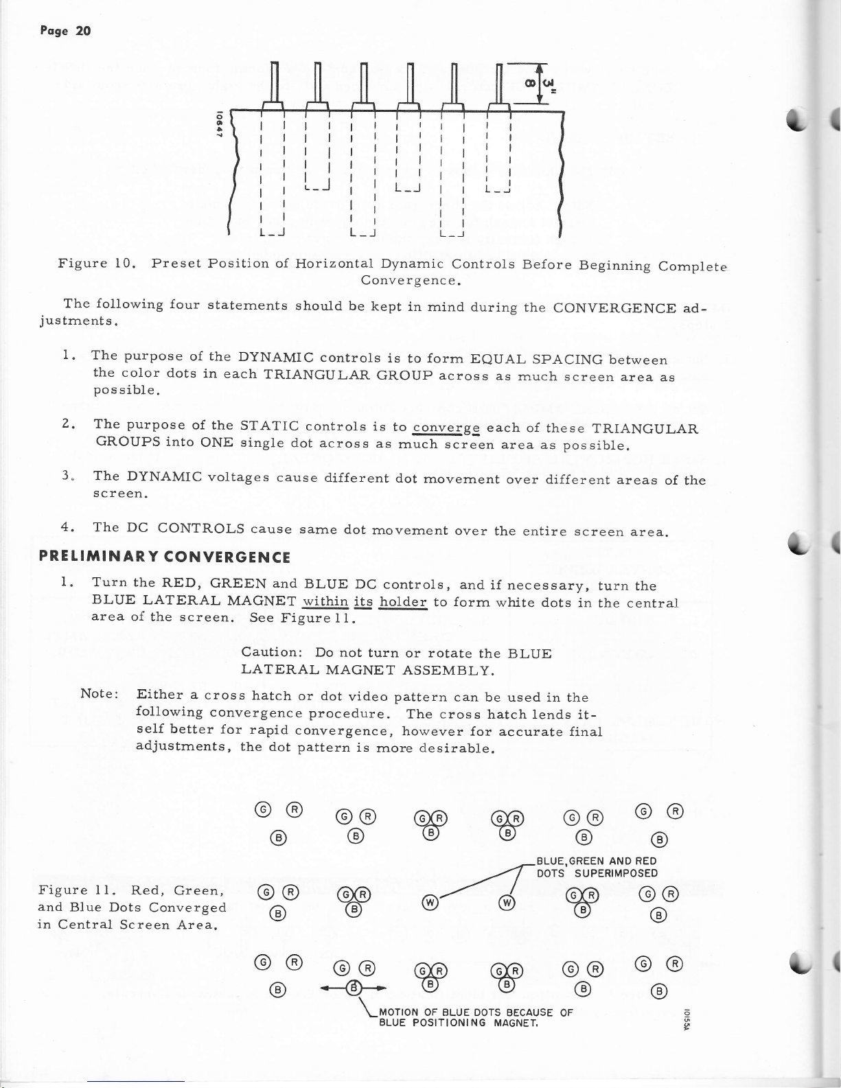
Figure
10.
Preset Position of
The
following
four
staternents
justrnents.
Horizontal
Dynamic
Controls
Be{ore
Beginning
Cornplete
Convergenc e.
should
be
kept
in
rnind
during
the
CONVERGENCE
ad-
o-
o
{
I
I.
The
purpose
of
the
DyNAMIC
controls
is
to
forrn
EeUAL
SPACING
between
the
color
dots
in
each
TR.IANGULAR
GROUP across
as
rnuch screen
area as
pos
sible.
The
purpose
of the
STATIC
controls
is
to converge
each of
these
TRIANGULAR
GROUPS
into
oNE single
dot
across
as
rnuch
screen
area as possible.
The
DYNAMIC
voltages
cause d.ifferent
dot
rnovernent
over
different areas
of
the
screen.
z.
3"
4,
The
DC
CONTROLS
cause
sarrle
d.ot
movement
over
the
entire
screen
PRE t !TIII
N
AR Y
CONVERGE
N
CE
area.
(
I.
Turn the
RED,
GREEN and
BLUE
DC
BLUE
LATERAL
MAGNET
within its
controls, and
if
necessary,
turn
the
holder
to
forrn
white
dots in
the central
@@
@@
@@
BLUE,GREEN AND
RED
DOTS SUPERIMPOSEO
area
of
the screen.
See
Fi.gure
t l.
Caution:
Do not
turn
or
rotate
the
BLUE
LATERAL
MAGNET
ASSEMBLY.
Note:
Either
a
cross
hatch
or dot
video
pattern
can be
used in the
following
convergence
procedure.
The cross
hatch lends
it-
seLf
better
for
rapid
convergence,
however
for accurate final
adjustrnents,
the
dot pattern
is
rnore
desirable.
Figure I 1.
Red, Green,
and
Blue Dots
Converged
in
Central Screen Area.
w
@4
@@
@o
--@+
(,
w
@@
@
@@
@
@@
@
w
@@
@
@@
@
@@
@
@@
@
OF
(
\-MOTION
OF BLUE DOTS
BECAUSE
BLUE
POSITIONING MAGNEI
Page 21
[-
i
i
1
Poge
2I
+
l
t
a
+
a
+
a
I
+
a
i
a
+
I
I
a
I
I
v
a
I
V
t
I
a
g
?
v
a
I
V
?
I
?
I
V
a
I
I
t
{
1
EFFECT
OF
RED
EFFECT
OF
GREEN
E-IFECT
OF BLUE
veni. ampr-.
cor,tinol veRr. aupl.
coNTRoL
vERT. AMPL. coNTRoL
ON
RED
DOTS
ON GREEN
DOTS
ON
BLUE OOTS
I
I
t
I
t
I
t
EFFECT OF
BLUE
EFFECT
OF
REO
I VERTTcAL
TILT
vERTIcALTILT
E on BLUE
oors
oN
REo
oors
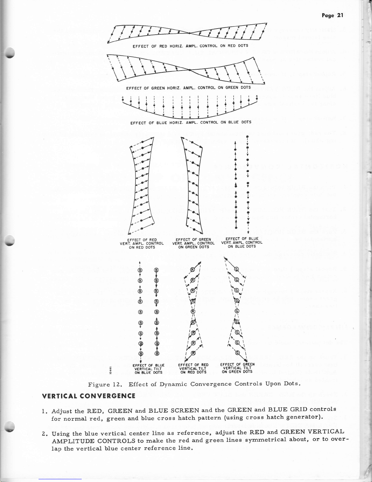
Figure
12.
Effect
of Dynarnic
Convergence
Controls
Upon
Dots.
VERTICAL
CONVERGENCE
I. Adjust
the RED, GREEN
and BLUE SCREEN
and the
GREEN
and BLUE GRID
controls
for norrnal
red,
green and
blue cross
hatch
pattern
(using
cross
hatch
generator).
2.
Using
the
blue vertical
center
line
as reference,
adjust the
RED
and
GREEN
VERTICAL
AMPLITUDE CONTROLS
to rnake
the
red
and
green
lines
syrnrnetrical
about,
or
to
over-
lap the
vertical
blue center
reference
1ine.
?
?
I
I
@
6
6
6
6
I
@
i
o
I
6
6
@
\
\\o
t\
''\')
\@/
9',
6
,Gl
rl
i\
(
@.\
.\,
b\
\
EFFECT
OF GREEN
VERTICAL
TILT
ON GREEN
OOTS
{l
(ll
t,q
Y
I
A
"P'),
tf,)
f
!
1
I
i
I
l
i
i
I
i
:
I
,
I
,l
1
I
I
i
I
EFFECT
OF
RED
HORIZ. AMPL. CONTROL
ON
RED OOTS
EFFECT
OF GREEN
HORIZ.
AMPL.
CONTROL
ON GREEN
DOTS
EFFECT OF
BLUE
HORIZ.
AMPL.
CONTROL
ON
BLUE DOTS
t'
Page 22
Page
22
3"
Statically converge
the
center
of the raster using
the DC convergence controls
and
the
blue
lateral
rnagnet.
4. Adjust
the RED and
GREEN
VERTICAL TILT
CONTROLS
to
obtain as
straight
a
verti-
cal center line as
possible.
5.
Repeat
step
3, if necessary.
6. Adjust
the BLUE
YERTICAL
TILT
and
AMPLiTUDE
CONTROLS
to make the
horizontal
blue lines
equally
spaced or coincident with
the
associated red and green horizontal lines
along
the vertical
axis
of the tube.
7.
Repeat
step
3,
if
necessary.
8.
The
red, green
and
blue
vertical center
line should be nearly coincident
(overlapped forrn-
ing white).
If
necessarlr
repeat
steps
2
through 7.
HORIZONTAL
CONVERGENCE
1"
TUTN thc
BLUE
HORIZONTAL
AMPLITUDE and
BLUE
HORIZONTAL TILT
CONTROLS
out
fully
counter-clockwise
(rnaxirnurn
arnplitude,
rninirnurn inductance).
2.
Turn
the BLUE
HORIZONTAL
AMPLITUDE
CONTROL in
(clockwise)
until the
blue
horizontal
center line
bows downward,
slightly
to the right of the
center of
the
screen.
3.
Turn
the
BLUE
HORIZONTAL
TILT
CONTROL in
(clockwise)
to obtain
as
straight a
horizontal
center blue line
as possible.
4" Statically
converge
the center
of
the
raster,
if necessary.
5.
Repeat steps
I through
4 with
the
RED
HORIZONTAL
CONTROLS.
The
bow in
the
red.
center line is slightly
upward,
just
to the right
of the
center of
the
screen
in this case.
6.
Repeat
steps
I through
4 with
the
GREEN
HORIZONTAL
CONTROLS. The
bow in
the
green
center
line is
slightiy
upward,
just
to the right
of the center
of the
sc:een
in
this case"
FINAT CONVERGENCE
The
dot
pattern should
be used.
1. Touch up the RED, GREEN
and BLUE
HORIZONTAL CONVERGENCE
CONTROLS
for
best over-a1l horizontal convergence. There
is some interaction
which causes
the
Arnplitude Control to
effect Tilt
and
visa
versa,
but in
general
the controls
can be
treated
as
labeled.
2.
Touch
up the
RED, GREEN
and
BLLIE VERTICAL CONVERGENCE
CONTROLS
for
best
over
-a11
vertical
convergence.
r(
t"{
3.
Set the
best
over-a11
static convergence using
the
DC
CONTROLS
and
the BLUE LAT-
ERAL
MAGNET. The blue lateral tnagnet influences slightly
the bearn
from
the
red
and
t
(
green
electron
guns,
therefore, after
rnaking
final adjustment of the blue
lateral rnag-
net, readjust
the
RED
and
GREEN
DC controls.
Page 23
Poge
23
TOUCH
I
UP
OF
PURITY
A
TOUCH-Up
of PURITY
rnay
be
required
on a
new
receiver
or
following
the
conver-
gence
adjustrnents.
In
either
case,
rnake
the
following
adjustrnents
until
good
purity is
achieved
for
the
red
field.
1. Perform
steps
Z, 3
and 4
under COLOR
PURITY
on
page 15.
2. Adjust
RIM MAGNETS
for
good purity
around
edges
of
raster.
3. SLIGHTLY
adjust
the tabs
on the
PURITY
RINGS,
if
necessary.
CAUTION:
ADJUSTMENT
OF
PURITY
RINGS
WILL
UPSET
CONVERGENCE.
HOWEVER,
THE
RESULTS
OF
A VERY
SLIGHT
ADJUSTMENT
MAY
BE NEGLI-
GIBLE
UPON
CONVERGENCE
AND
MAY
IMPROVE
PURITY.
4. Perforrn
step
12 under
COLOR
PURITY.
TOUCH
-
UP
OF
CONVERGENCE
A TOUCH-Up
of CONVERGENCE
is
not arrshort-cutrrfor
correctly
adjusting
the
re-
ceiver
for convergence.
Careful
reading
of
the CONYERGENCE
procedure,
or
previous
experlence
in rnaking
convergence
adjustrnents
will
aid the
servlce
technician
to deterrnine
whlch
controls
rnight
need a slight
touch-up.
It rnay
be found
that
following
the COLOR
PURITY,
CONVERGENCE
and
TOUCH-UP
of
PURITY
adjustrnents
that CoNVERGENCE
rnay
also
need
a
touch-up.
A touch-up
procedure
for
convergence
is
(1)
to
fo1low the
step-by-step
procedure
given
under CONYERGENCE
(cornplete
set-up)
and
(2)
rnake
only
the
adjustrnents
which
are
nec-
essary
to obtain
the
results
rnentioned
in each
step.
If
the
receiver
requires
only
a
touch-up,
the
adjustrnents
under
CONVERGENCE
will
be
easier to rnake
and
will take
less time.
BLACK
ond
WHITE
TR'ACKING
The
purpose of
the BLACK
and
WHITE
TRACKING
adjustrnent
is
to
produce
a
good
black
and while
picture within
the
usable
range
o{ the
Brightness
and
Contrast
controls.
If
this
adjustrnent
is
not
properly
rnade,
a
black
and
white
picture
will
appear
tinted
with
color
as
the Brightness
or Contrast
controls
are adjusted
and a color
picture
will
be
re-
produced
with
the wrong
colors.
Tune
in a
station
that
is transrnitting
black
and white
pictures.
Make
adjustrnents
as follows:
1. Turn
the
CONTRAST
CONTROL
cornpletely
to minirnurn.
Z.
Turn the GREEN
and BLUE
GRID CONTROLS
to
extrerne
left
(rninirnurn).
3. Adjust
the RED,
GREEN
and BLUE
SCREEN
CONTROLS
to
about Ll2
rotation
clockwise.
At these
settings
the
picture
should
be
red when
the
brightness
is
turned
up.
4. Adjust the
Brightness
control
until
the
picture
is
just
extinguished.
Page 24

Poge
24
5.
Turn
the
GREEN
GRID control
completely
to
the right and
then reduce
the setting
until
the green
light
just
disappears.
6.
Repeat step
5 for
the BLUE
GRID control.
7.
If the
picture
appears
GREENISH,
turn
GREEN SCREEN
control very slightly
to the right.
Then
turn
GREEN
GRID control
to the left until
picture
is black and
white.
If the
picture
appears
BLUISH,
turn
BLUE
SCREEN control very
slightly
to
the
right.
Then
turn
the BLUE
GRID control
to the le{t until
the
picture
is black and
white.
If the
picture
appears
REDDISH, turn
RED SCREEN control
to the left until
pic-
ture is
black and
white"
8.
If
picture
is
sti1l
not
black and
white, repeat
entire
I'Black
and
\{hite Tracking"
proc
edure.
CIRCUIT
DESCRIPTION
VHF
TUNER
The
YHF tuner,
94D131-1,
features
high
gain
and
stability and
inherent
high signal
to
noise ratio.
Drift
has
been
rninirnized
by
the use of rugged
tuner construction and
ternpera-
ture
compensated
capacitors.
Sirnplicity
of
design
and
Printed
Wirlng will reduce
service
requirernents
to
a
rninirnurn.
Much longer
tube
life
is
rnade
possible
by the neutralized
triode
circuit. This
single
triode
has Iess
than
half
the dissipation
of a dual-triode
cascode.
A desirable feature
of the
tun-
errs circuitry
is
that it is
designed
to operate on a relatively
low
B-Plus
Voltage,
as 1ow as
125
volts,
thus assuring
longer
life
to cotrrponents and
tubes.
The 6BN4 is
used as a
neutralized
triode
RF
arnplifier.
The input
transforrner
T101
rnatches
the 300 ohm
balanced input antenna
lead-in to
the
unbalanced 75 ohrn input of the
trrner.
The signal
then is
applled
to two IF traps, one
paralle1,
one in
series.
These
traps
are
stagger-tuned
to
provide
optirnurn
IF
rejection
over
the
range frorn 4l
to
46
MC.
The
capacitor
C121
reduces
oscillator radiation.
f'rom
antenna
coil L102A, the
signal is
ap-
plied
to grid
of
the 68N4. AGC
bias is applied
to this
grid.
Capacitor Cl05
varies the
arn-
plitude
of
the
180
degree phase
shifted signal from
the
plate
circuit to
neutralize the
plate
to
grid
capacitance.
The output
of the
triode is rnutually coupled
to the
input tuned circuit
of the
pentode
Mixer 5CG8.
Cl08 tunes the
plate
circuit of the RF Arnplifier. Cl10
tunes
the
grid
circuit of the
rnixer stage.
rl
L(
The locaI oscillator
circuit
of the tuner is a conventional
Colpitts
circuit with
rrBookrr
fine
tuning. The fine
tuning
stator area in
the
plate
circuit is
printed on the board. A
hinged tin-dipped phosphor
bronze
plate
is separated by insulating tape
frorn
this
printed
atea.
FIence,
"Book
Tuning".
The
Fine
Tuni.ng control
provides a
tuning range
of.
frorn
Z
to 4.5
MC
on
all
VHF
channels.
L
(
'When
replacernent
ls
rnade of
feedthrough
capacitors
Cl)Z,
CL04,
C109, CLLZ, CI13,
CI15, exact
replacement
feedthrough
capacitors should be used.
Page 25

Poge
25
TIIXER
IF COUPLING
NETWOR,K
The rnixer
IF
coupling
network
is
rnade
up of
four
tuned
circuits,
two tuned
to IF
fre-
quencies
(Ll05
and T201),
an adjacent channel
sound trap
(L202)
and
a trap
(L201) for
at-
tenuating
the
sound carrier.
The rnixer
plate
circuit
is luned to
4?.4
MC,
and
is
capaci-
tively-coupted
to the IF
input circuit
which
is tuned to
approxirnately
46.0
MC.
Capaci-
tance-coupling
is used to rninirnize
oscillator
radiation.
The trap
(L201),
tuned
to
41
.25
MC,
attenuates the
sound
carrler
approxlrnately 30
db to
prevent
the
herringbone
Pattern
on the
picture
tube
caused
by the
920
KC
beat
between the
sound
carrier
and color
sub-
carrier.
Cross
modulation
is the rnodulation
of the
desired
signal
by
an
unwanted
signal
or
inter-
ference
such as
adjacent channels. To
rninirnize
interference,
an adjacent
channel
sound
trap
(LZOZ)
in
the
rnixer-IF
coupting
network
provides approxirnately
46
db rejection
at
47.25 MC.
VIDEO
IF
CHANNEL
The
video IF
channel consists of
4 stages
of IF
amplification
using three
6B26 tubes
and
one 6CB6
tube.
The
channel
is designed
for a 45.75
MC
video carrier,
a
42.17 MC
color
sub-carrier
and a
41.25 MC
sound
carrier. The
first
and second
stages
are
tuned
to
the
video
and color sub-carrier
frequency
sides of
the
IF
response curve
(46.0
MC
and
45.1
MC)
so that the sound carrier
is kept
at a low
arnplitude
as long
as possible to
further
pre-
vent cross
rnodulation.
The third
stage is tuned
to
approximately
center
of the IF
response
passband
(43.2
MC)
and serves
as a
trtiltrt
control.
The
'rtiltI
is adjusted to
produce
a flat
response over the
passband of
approxirnately 4
MC
at
the 6
db
points on the IF
response
curve.
The
first, second
and
third IF
amplifiers
are controlled
by
autornatic
gain control.
To
further
rninirnize
cross rnodulation
the tubes
are of
rernote cut-off type.
The
screen
grids
on these three
tubes
are
rnade
{urther
rernote by using
a dropping
resistor in the
B
plus
line.
LUTIIINANCE CHANNEL
The
lurninance
(Y)
channel
function is
sirnilar to that
performed
in black
and white
re-
ceivers
--
that of
arnplifying
the lurninance
inforrnation to
the
required
arnplitude to
drive
the
picture
tube
and adjusting
the
peaking of the video
circuits
for
fine detail
in the
picture.
The
rrYrr
channel
consists
of the
lurninanie
detector,
delay line
and
one stage
of
arnplifica-
tion caIled Luminance
Output.
The
lurninance
detector
(CR20I)
is
a gerrnaniurn
diode
and is operated
at 7.0 volts
peak
output level.
A crystal
has
a rrrore linear
characteristic
resulting
in better
arnplitude
re-
sponse
for
the
gray portions of
the
picture.
Also, a
crystal
diode was
selected because
lts
physical size
provides easier
shielding
for IF
harrnonics.
The
srnall
diodes
have
less
shunt
capacity
providing less loss to
hlgh
frequencies.
Irnrnediately
following the
lurninance
de-
tector
is an
IF
bypass condenser
(C218) and
a series
rejection coil
(L20?)
tuned
to 43.5
MC.
These two cornponents
filter out
any IF or RF
signals that
rnay
have
passed through
the
lu-
rninance
detector.
Delay Llne- Slnce
the lurninance
signal
has
a wider
ovet-aIl
bandwidth
than the
chrorni-
nance channel,
it rnust
be delayed
in
order
to
insure
that the two
signals
arrive
at the
pic-
ture
tube
at
the
sarne tirne.
The lurninance
signal
thus
is
delayed
.8
rnicrosecond
in
the de-
lay line.
The
series
peaking
coil
(LZ10) in the output
o{
the
delay
line
is to rninirnize
reflections.
A modified bridged T
trap
(L211) foliowing
the
delay
line
provides
rejection
at 3.58
MC.
p.ZZ3,
4,300 ohrns
resistor, serves
as a detector
load,
a termination
for the
delay
line,
and
the
center leg
of
the
bridged T.
Page 26

Poge 25
Lurninance
Outpg!,
V205
-The
single
stage
to
the picture
tube
cathodes,
thus
achieving
in
the luminance
amplifier
cathode functions
gain
and
bandwidth
in
the
plate
circuit
of the
used between peaking
coils.
LZBYT
lurninance
arnplifler
is dlrect-coupled
DC
restoration.
A
variable
resistance (R225)
as a
Contrast
control.
To
achieve greater
lurninance arnplifier,
rnutual inductance is
{
SOUND CHANNEL
The sound channel
consists of
and
audio output.
The
sound
and
video IF
transforrrer.
a
detector,
IF
arnplifier,
ratio
detector,
audlo arnplifier
chrorna are
taken frorn a separate winding
on the
{ourth
The 4.5
MC
intercarrier
beat is detected
in
the cornbination
sound and
chrorninance de-
tector.
The gerrnanlurn
dlode
used here is
the
sarne
as is used in the lurninance detector
stage,
Adrniral part
nurnber
93A8-1.
The input
transforrner (L301)
feeds
the 4.5
MC
sound
IF to the
grid
of
the
pentode
sec-
tion
of
a
6Ug tube, sound
IF arnplifier.
A
conventional
ratio
detector
stage
is used to
re-
move
the
audio
inforrnation
frorn
the
sound
IF
carrier.
The
remaining
triode
section of
the
6U8 tube
is
used as
the
first
audio arnplifier.
A
tapped volume control
(R308)
and
fre-
quency
cornpensation
network
in the
grid
circuit
provide
good
low frequency
response
even
at low settings
of
the
control
.
A rnanual
tone control
(R3
14) is inserted
ln
the
plate
circuit
of
the
first
audio stage.
The audio
output
consists
of
one 6Y6 tube.
CHROMINANCE
CHANNEL
The chrorninance section
of
the
color
receiver rernoves
the color
inforrnation
frorn
the
cornposite
video signal,
builds it up,
dernodulates it and
distributes
it in
proper proportions
to the
three
guns
in
the
picture
tube.
Several
stages work together to
perform
these
tasks.
Chrorninance Detector
-
A
gerrnaniurn
diode, Admiral
part
nurnber
93A8-1,
is
used
as
a
cornbination chrorninance and sound
detector. The diode is the
sarne
type
as
the
lurninance
detector diode.
Provisions
are
rnade
for
the
necessary
by-pass
and
peaking
networks.
A4.5
MC
bridged T trap
(L401),
located between the chrornlnance
detector
and first
chrorna
arnplifier, prevents
the
sound IF
frorn
entering the chrorna
channel. This trap
pro-
vides
26 db attenuation
to 4.5 MC.
Chrorna ArnpliIier.E
-
The three interstage circuits
in
the chrominance
ampliflers
are stag-
ger-tuned,
sirnilar
to video IF
arnplifiers,
to
provide
a
1 MC
flat bandpass. The two
high
elernents in
the
grid
and plate
circuits of the
first
chrorna
amplifiers
are
tuned to
4. I
MC
and
3.
1
MC,
respectively.
Figure l8a shows a typical
response of
two
such circuits"
The
plate
circuit
of
the chroma output has
a
slightly broader response
with less
arnplitude
(see
Figure 18b) and is
tuned to 3.58
MC,
approxlrnately
rnidway
between 3.1 MC
and
4. I MC"
The
three-stage
stagger-tuned response
is shown
in
Figure
18c, flat
for the fuIl 1 MC
band-
pass required
for
good
color detail.
The
input impedance of the
output
stage is lower than
the
output irnpedance
of the
first
chrorna
arnplifier.
Matching
is
accornpllshed
with the
2:1
turns
ratio
inter-stage
coupling
transforrner
T401. The chrorninance
output
is coupled
to
the
dernodulators
through capacitors
C4Z6
and
C427.
t
L(
Page 27

?oge
27
3,58
+
,At
(o)
(b)
(c)
Figure
13. Typical
Response
curves
of Three
stagger-Tuned
circuits.
Four
voltages
are
present
at
the
grid of
the
first
chrorna
arnplifier.
Let
us
consider
each
of
these
voltages
individually:
A. The
chrominance
signal
,
containing
hue
and saturation,
is coupled
to
the
grid through
a
3.3
mrnfd
capacitor"
Due
to the
high
irnpedance
at low
frequencies,
this
capacitor
passes
only
sidebands
suppressed
3.
58MC
sub-carrier.
B. During
color
reception,
a
positive
pulse
frorn the
color
intensity
control
is coupled
to
the
grid
of
the {irst chrorna
arnplifier through
capacitor
C503
and coils
L402
and L403.
The
arnplitude of this
pulse
can
be varied
rnanually
by the
color
intensity
control
between
0 and
90
volts,
peak
to
peak.
The
bias
developed
at
the
grid varies
in
proportion
to
the
arnplitude
of the
pulse.
The
gain
of
the tube
varies
inversely
proportional
to the
arnpli-
tude
of the
pulse.
C.
During
black
and
white
reception
the Color-ki1ler
tube,
V401B,
conducts
and
provides
a
positive
pulse
to
the
grid of the
first
chrorna.
This
pulse,
approximately 80
volts,
peak
to
peak,
autornatically
accornplishes
the
same
result
as
described
in
steprrBil
above
in
the
absence of color.
D"
Aulornatic
Chrorna
Control
voltage
(cornparable
to
autornatic
gain control)
is the
fourth
voltage
applied to
the
grid
of the
first chroma
arnplifier
tube.
The
ACC
voltage,
de-
scribed
under
the heading
of Autornatic
Chrorna
Control
is
developed
in the 3.58
MC
phase d.iscrirninator
stage. The
arnplitude
of
the incoming
burst
determines
the
amount
of ACC
voltage
fed back
to
the
grid
as
gain control
voltage'
In
brief;
d.uring
color
reception,
the
first
chrorna
arnplifier
conducts
fully
during
hori-
zontal retrace
tirne
and
according
to the
selting
of
the
color
intensity
control
during
hor-
izontal trace
tirne" During
black
and white,
the
tube
conducts
only
during
horizontal
re-
trac e tirne .
Burst
Arnplifier,
V501B
-
The
color
trbursttr
signal
consists
of
8 to
11 cycles
of the
3"
58
MC
."rri."
*ua
in tha
b"t"nced
rnodulators
in the transrnitter.
Hence,
the
rrburstrrcon-
tains
the
sarne
frequency
and
phase as that
of
the
rnissing
subcarrier
and is used
in the
re-
ceiver
as
the Color
Synchronizing
signal.
This
color
sync
signal
appears
during
horizon-
tal
retrace
period
on
the
back
porch of the
horizontal
blanking
pulse.
The
color
nburstrr
signal,
arnplified
in the
first chrorna
arnplifier
tube
during
horizontal
retrace
tirne,
is taken
off
at the
interstage
coupling
transforrner
T40t
and
applied
to
the
grid
of
a pentode
burst
arnplifier
tube V50IB.
To
insure
trburstrr
separation
frorn
the
chro-
rninance
signal,
the
cathode
of the
burst
arnplifier
receives
a
negative
gating
pulse which
allows
the tube to
conduct
only
d.uring
the
horizontal
retrace
gating
pulse tirne.
The
arnpli-
tude
of the
gating
pulse is
approximately
45 volts,
peak
to
peak. The
arnplified
t'burstil
sig-
nal,
approxirnately
200 volts
peak
to
peak,
appears
in
the
plate circuit
and
is
developed
a-
cross
the
plate
load
coil, L50I.
This
"burst"
signal
is
applied
to
the
color
phase
discrirn-
inator
through
capacitor
C511.
f
E
I
o
1U
rp
Page 28

Poge
28
Color
Phase
Discrirninator,
V50Z
-
The function
of
the color
phase
discrirninator
is
to
coryIpare phase
and
frequency
of
the 3.58
MC
recelver
oscillator
signal with
incorning burst,
the color
sync
signal.
The output
of
the
discriminator
in
the
forrn
of a
DC voltage is used
to
provide
automatic
frequency
control of
the
receiverts
3.58
MC
oscillator.
This
sarne out-
put
is used
to cut-off
the
Color
Killer
during
the
presence
of
color
burst.
An
add.itional
output
voltage is
used
to
control
the
gai.n
of
the lst chrorna arnplifier,
depending
upon the
level
of burst.
The inputs
to the phase
detector
consists
of a
Push-PulI
(Positive
and
Negative)
3.58MC
oscillator
signal and
the color
burst
signal.
On
a color
signal,
burst and
oscillator
inputs are
cornpared
in
frequency
and
phase,
"Positive
going"
3.58
MC oscillator
signal
to one
diode and
rrNegative
goingtr oscillator sig-
nal
to the
other diode
with the
burst signal
cornrnon to both diodes.
Each
diode
conducts
equally
when
the
phase
of burst
is
!0
degrees displaced
frorn
the
3.58
MC oscillator
signal appearing
at
either
cathode.
The 3.58
MC oscillator signals ap-
pearing
at
the
two cathodes
are,
of course,
of opposite
phase (180o).
lVhen the diodes con-
duct
equal1y,
therrvoltage
dropstracross
each diode load resistor,
R5Zl
and
R5ZZ,
are e-
qual
and
of
opposite polarity.
The
oscillator
control
tube,
Y5034,
requires
a srnall
value of operating
bias;
therefore,
the
oscillator
tank
coil
is adjusted
for
a
negative
six
(-6Y)
volts
at
Pin I cathode.
This sarne
negative
six
volts is applied
to the
color killer
tube
grid
to effect its
cut-off during
color re-
ception.
'When
the frequency
and phase
relationship
between
the
oscillator
voltage and
the incorn-
ing
burst signal
is
correct,
the
color
phase
discrirninator
supplies
norrnal
operating
bias
to
the grid
of
the
3.58
MC oscillator
control
tube,
V503A.
If the 3.58
MC
oscillator
increases
slightly
in frequency,
a
rnore positive
voltage
is developed
and
applied
to
the
grid
of the os-
cillator
control
tube.
This
will essentially
increase
the
capacitance
of the
control
tube
which
shunts
the
oscillator
tank,
thus reducing
oscillator
f.requency.
If the oscillator
frequency
d.e-
creases
slightly
below
3.58
MC,
a
more negative
voltage
is developed
and applied
to
the grid
of the
control
tube,
thus
decreasing
the capacitance
and
increasing
the frequency
of the
3.58
MC
oscillator"
ACC
-
Arrtornatic
Chrorna
Control
-
The
autornatic
chrorna
control functions
sirnilar
to
ar1
autornatic
gain
controt
on
black and
white receivers.
A negative
voltage deterrnined
by
the
arnplitude
of
the incorning
burst
signal
is fed
back
to the
first
chrorna arnplifier grid
to in-
crease
or decrease
gain
through
that
stage"
The
first
chrorninance
arnplifier
also
arnpli{ies
the
color burst which
i.s separated. frorn
the
chrorninance
signal
by rneans
of a
gated
burst
arnplifier
tube.
This
separated.
high-alti-
tude burst
is fed
to
the
phase
detector
where it is
cornpared
with
the output of
the 3.58
MC
oscillator.
The balanced
negative
output
of the
phase
detector
is
a
rneasure
of the relative
burst
signal
arnplitude;
this
control
voltage is
applied
to
the
first
chrorninance arnplifier
to
provide
Autornatic
Chrorninance
Control.
I
The
color intensity
control,
R
505, is a
rnanual
tive horizontal
retrace
pulse
applied
to the
grid
of
the chrorninance
arnplifier
varies inversely
as
the
burst
output
rernains
nearly
constant.
chrorninance
control.
By
varying a
posi-
the
first
chrorninance
arnplifier,
output
of
arnplitude
of the horizontal pulse
while
the
3.58
MC
Oscillator
Control
V5O3A
-
The 3. 58
MC Oscillator
Control tube is used
to
cor-
MC
oscillator.
The
arnount
of frequency
or
rect
the
frequency
or
phase
drift
of the
3.58
Page 29

poge
29
phase
correction
depends upon the
amount of voltage
developed
by
the
phase discrirninator
tube.
The
phase
d.iscrirninator
develops correction
voltage
in
proportion
to the
arnount
of
frequency or
phase
drift.
The
correction
voltage is
applied to the
grid
of
the control
tube.
A
positive or negative
change
in
grid
voltage
will
result
in
an
increase
or decrease
in
plate
current,
in turn
re-
sulting
in a
decrease
or
an
increase
respectively,
in oscillAtor
frequency. This
systern
provides
very
accurate stability.
3.58
MC Oscillator,@-The
3.58
MC
voltage
is
produced by
a
crystal
controlled
os-
"iti"tor,
the
pentode section of
a 6U8. The
crystal is
connected
between
the
grid and
screen.
Electron
coupling
to the
plate produces
sufficient
signal
in the
plate
circuit
of the oscillator
to
drive
the
phase
discrirninator
and the triode
dernodulators.
Transforrner,
T502,
in the
plate
circuit
provides
such
signal voltages.
Chrorninance
Dernodulators,J!!!
-
Two triode
color
dernodulators
of
high
arnplification
are..s"i[ to
derrrodrrlate R-Y,
B-Y
and
G-Y
frorn
the chrominance
signal' This
high
leve1
type of
dernodulator
provides
adequate output
to
drive
the
picture tube
directly
with
good
linearity,
DC
stability,
and independence
of tube
characteristics.
The
chrorninance
signal
is fed
at high-arnplitude
to the
plate while the
3.58 MC
signal
is
applied to the
grid. The
grid circuit
is self-biased
and
driven
with
sufficient
voltage
to'as
-
sure class
C
operation. The
plate receives
adequate chrorna
signal to
drive two
of the
three
guns in
the
picture
tube
plus a srnaller
arnount
that
is subtracted
frorn
the
plate circuit
and
taken
off of the
cornrnon
cathode
to drive
the third
gun"
This
circuit
takes
advantage
of the
fact that the
G-Y
signal
requirernents
are
the
srnallest
of the
three
color
difference
signals,
and. that the
G-Y
can be rnade
up
of the
negative
of
R-Y
and
B-Y
since
G-Y= -.51
(R-Y)
-.19
(B-Y).
The G-Y
signal
produced in the
cathode
circuit
subtracts from
the B-Y
and
R-Y
sig-
nals
produced in
lhe
plate
circuit. Therefore,
sufficient
chrorna
drive rnust
be
applied to
the
plates
to
produce
the
cathode signal
as well
as
the
plate signal
.
To
etrirninate the cross talk
between
R-Y
and
B-Y
which
would
norrnally
exist
due to the
cornrrron cathode irnpedance, the R-Y
and
B-Y
dernodulating
reference
voltage
angles
are
rnoved toward each
other
frorn
their
quadrature
(90o
separation)
position
to cancel
out the
introduced cross talk. The R-Y
dernodulator
axis
is
rnoved I2.
t
degrees
away frorn
R-Y
in
the direction of B-Y. The B-Y
dernodulator axis is rnoved
13.5
degrees
away frorn
the
B-Y
in the
direction
of
R-Y.
Total
separation o{
the
dernodulator
axis is 63.6
degrees.
The operation
of the high
level
color
dernodulators
differ
frorn the well-known
diode de-
tectors
used
in
black
and
white
TV
and in the color set, to
obtain lurninance
inforrnation
frorn
the rnodulated carrier. There
are
two
reasons for this
difference.
l.
Z.
To
obtain
three
outputs
(red, green, blue)
frorn
one
signal it
is neces-
sary to
detect
the
signal
at phases, other lhan the
carrier. Two
sig-
nals
are
detected
(R-Y
and
B-Y)
and
the
third
(G-Y)
is developed
by
adding together
portions of the
first
two
signals
detected.
As
a result red,
greerr and bLue are not detected
in the
color dernodulators,
but
R-Y
'
B-Y
,
and
G-Y
where
Y
represents
the
black
and white
or lurninance
signals.
Use
isrnade
o{
the
picture
tube
to
add
together
the
chrorninance
information
received frorn the
color detec
Color
inforrnation
is
transrnitted
by
in order to
detect these signals
it is
the
receiver.
This
carrier rnust
be
color carrier transrnitted.
a suppressed
carrier
systern
and
necessary to
supply
a carrier
at
synchronized
to
burst, the
only
Page 30

Poge
30
tors,
and the
lurninance inforrnation received from ihe luminance
arnplifier
to
produce
the
final red,
green
and
blue signals.
This
is done
by DC coupling the
black and white
inforrna-
tion to
the three cathodes of
the
picture
tube,
while
the three
outputs of
the
color
dernodula-
tors
are
DC coupled to the
respective grids
of
the
picture
tube.
The
chief
requirernents
for proper
operation of the
dernodulators
are--
I. The correct ratios
between the separate
plate-load
resistors
and
the
cornrnon
cathode
re sistor.
2.
The correct
phase
relationship between the two
reference
CW
signals
which
are applied
to the
grids.
Detection
of
the chroma
signal is accornplished by causing the
two triodes
to
act as grid
controlled
rectifiers.
The 3.58
MC
sine wave
voltage
frorn
the crystal
controlled
subcarri-
er
oscillator is applied between
grid
and
cathode
of the
R-Y
detector. To
detect
at
correct
phase
for
the
B-Y
detector,
a
two stage
phase
shift network is used. This
network delays
the subcarrier applied to the
B-Y
detector so that correct outputs
are
produced.
This
C\tr
voltage is
great
enough so that the
dernodulator
tubes
operate class
C;
that
is,
each tube
draws
current
for
only
a
very
short
tirne
during each cycle. Thus,
the tubes
oper-
ate"as switches,
turning or'). once each cycle. The
bias on
the
tubes
is
deterrnined by
grid
conduction,
and
by the
parallel resistance-capacitance network in each
grid.
The
series
resonant coils
L407, L408
and
L409
{ilters the
3.58 MC
component
in
the
output circuits.
Phase Shift
Network,
MM
-
Since
one of the two chrorninance
dernodulators
requires
a
phase
difference signal,
a
phase
shift network is used to
provide
the exact
arnount of
shift.
One
of the secondary windings
on the 3.58 MC
oscillator output transforrner,
A502,
supplies
the
3.58
MC
signal to
the two
dernodulator
stages.
One
dernodulator, V403A,
receives the
3.58
MC
signal direct;
the other
dernodulator,
Y4038,
receives
the
signat
that
has been
de-
layed. A two-section low-pass filter
having
a 560
ohrns
characteristic
irnpedance
provides
63.6
degrees
phase
shift,
The
use oftwo-sections rnakes the
value of
circuit cornponents
less
critical
and
irnproves
stability.
Only
one
adjustrnent is
reguired to obtain
63.5
degrees
relative
phase
shift;
see
Phase Alignment
on
page
48.
Pulse Shapgl,
V50lA
-
The
purpose
of the
pulse
shaper
circuitry
is
to
narrow the
positive
gating pulse
which is
applled
to the first chrorna
arnplifier,
Y40lA.
If
the
pulse coupled to
the
first
chrorna
arnplifier
is too wide,
it
rnight carry over
into
chrorna tirne
which would
distort
the chrorna
inforrnation
appearing on
the
left
side of
the
plcture.
The
pulse
shaper
tube
is a cathode follower. The
grid
leak
provided
places
the
operati.ng
point
o{ the tube at
cut-off
until
the
positive gating
pulse
applied to
the
grid goes sufficiently
positive
to
cause conduction. Thus the
positive
pulse at
the
cathode will
appear
only
during
this
shorter tirne.
This
is because
the
gating pulse is
progressively narrower
as it
ap-
proaches
its
positive peak.
Color Killer,
Y
a
)
I
I
I
I
I
I
o
@
@
o
0
ru
Poge
3l
BI'RST
-(
E-Yl
Figure
14.
Vector Diagrarn
Showing
Relationship
of Axes.
Demodulator
Axes
Shown in
Heavy
Lines.
Due
to the long
RC tirne constant
in
the
grid
circuit, the tube
rernains cut-off until
the
next
pulse.
The
arnplifier is
held beyond cut-of{
(during
scan
tirne) untl1
another
pulse appea?s
(during
retrace
tirne).
Thus
no
video
passes
through the
chrorna channel
during
black
and
whlte
transrnission.
'When
color
burst
is present at
the input of the color
phase discrirninator,
a DC voltage,
negative
polarity,
is developed at pin
#l
cathode
of the color
phase discrirninator. This
voltage
supplies
norrnal
operating bias to the 3.58
MC
oscillator control
tube,
and cut-off
blas
to the color
killer
tube.
Thus
the
color killer is cut-off
during
color transrnission
and
will
not disable the
chrorna channel.
The
first
chrorna
arnplifier
conducts
during
color transrnission
and
conducts
only during
retrace
tirne during black and white
transrnissions.
The
color
killer
conducts
during black and
white transmission
(retrace
tirne
only)
and
is
cut-off during
color transrnis
sion.
-
(R-Yl
J
Page 32

Poge 32
AGC- A
gated pentode
circuit
provides
autornatic gain
control
bias
for
the
grids
of
the RF
and first
three
IF
arnplifiers,
based on the lransrnitted sync
pulse
level. The
grid
of
the
gated
AGC tube,
Y206,
is
supplied with
the cornposite video signal voltage
frorn the
output
of the video arnplifier by direct
coupling
through
isolating resistor,
R605.
Pulsed
plate
voltage of 500
volts
peak
to
peak
developed during
horizontal
retrace
tirne,
is obtained
frorn
a winding
on the horizontal
output
transforrner
and is
coupled to the
plate
of the
AGC tube
through capacitor,
C603. Since DC voltage
is not applied
to the
p1ate,
the AGC
tube
con-
ducts only during
the horizontal
sync
pulse
interval.
The
amount
of
plate
current conduc-
tion during
this interval depends upon
the
arnplitude
of the transrnitted
sync
pulse and, in
turn,
determines
the
arnount
of
AGC voltage
developed by
the AGC
tube. The
transrnitted
sync
pulse
arnplitude
is
used to
deterrnine
the
arnount
of AGC
bias developed because this
is
a
constant
arnplltude
with respect
to the transrnitled carrier,
representing 100/o of carrier
power.
If the
average
composite video signal were used to deterrnine the
amount of AGC
blas, the
AGC bias
voltage would vary with changes
in
the
average
picture brightness being
transrnitted.
An AGC voltage divider,
rnade up of
R604,
R2
14
and
RZl6,
supplies three
different arn-
plitudes
of bias; first and
second
IF AGC
is approxlrnately
twice
that of the
third IF
and the
tuner AGC varies
widely
as
iacorning signal strength
varies. On
a
strong
signal,
tuner AGC
rnay
be several
tirnes
Lhat
on
the
IF
stages.
On
a weak signal,
tuner AGC
is below that
of
the
IF
stages
to
provide
better signal-to-noise ratio
through the tuner,
resulting
in less
snow in
the
picture.
A slightly
positive
voltage is applied
to
test
point'rU't
that cancels
part
of the tuner AGC
providing
rnore signal
gain
in
weak
or interrnediate
signal
areas.
This
srnall
positive
voltage
is
called
"Delay
Voltage't.
ErcS_Se,p"r"t""
""a
N"i""
l,l
,-y6.!.L-
This circuit
is
used
to
irnprove sync stability in
nolsy
slgnal
areas by
elirninating
noise
pulses
that
occur during vertical
and
horizontal
sync
pulse
intervals.
The cornposite
video
signal is applied
to
the first
and
thtrd
grids
of the
sync separator
tube, 5CS5.
The
signal
on the
first
grid
(pin
l)
ls
negative (negative going sync
pulses) and
is
obtained
frorn
the
grid
of the video arnplifier
through a 47
K
resistor,
RZZZ.
This
signal
is
the
sarne
as
the output from
the video
detector.
The
signal on the third
grid
(ptn
7)
is
positive
and
is obtained frorn
the output of the video
arnplifier.
The
amplitude of this
sig-
nal is rnuch larger
than that on
the
first grid and
is 180 degrees
out
of
phase.
The
negative
AC
and
DC voltages,
developed across
video
detector load
resistor,
RZZ3,
are applied
to the
first grid (pin
1) of the 6CS6 through
an
isolatlng
resistor,
RZZZ,
47,000
ohrns.
The
first grid
ls so
biased
by this
voltage
and
the
positive
(bucking)
voltage
frorr.r
the
385
volt
supply
through the 2.2
rnegohrn resistor,
R610,
that
any pulse greater
than
the
arnpli-
tude of the sync pulses
will cut
the
tube
off and prevent
these noise
pulses
frorn
entering the
synchronizing
circuits and
triggering
the
vertical
and
horizontal oscillators.
If
a nolse
pulse
is superirnposed
on
lhe
sync
pulse,
the action of
the circuit will
elirni-
nate
both
the noise
and
sync.pulses.
W'hen
sync pulses are
lost in this
manner, the
,'fly
wheelrreffect
of
the
oscillators
will
keep thern synchronized
untll the next sync
pulse
ar-
rives.
Capacitor
C607
provides
coupling
to the
grid
of
the
Slmc Inverter Stage.
9ygg_I.rurt*,
V60ZA
-
The negative
going
sync
pulses
frorn
the
plate
of the
slmc
separa-
tor are
applied
to the grid
of
the sync inverter.
Due
to
the
high
value
of
grid
leak resistance,
R618,
and sorne
cathode bias,
the
sync in-
verter also
operates
as a
sync
clipper.
Negative
going sync
pulse peaks
drive
the tube to
cut-off,
resulting
in sync
ctipping
or arnplitude
lirniting
action.
{
t
(
L{
Page 33

poge
33
Negatlve
going
clipped
sync
pulses
frorn the cathode
of the
sync
inverter
are
applied to
a
cathode
of
the
sync discriminator through
a
coupling
capacitor,
C609.
Positive
pulses
of
approxirnately equal
arnplitude
are taken
from
a
voltage
divider
con-
sisting of
resistors R6l5
and
R616
in
the
plate
circuit
of this
stage
and are
applied to
a
plate
of the
sync
discrirninator
through
a coupling capacitor,
C508.
The
coupling
capaci-
tors
are
low in value
to
reduce
feed-through
of the vertical
sync
Pulses.
Color
Stripe
Tes.!
-
A
test
point is
provided on the
rear
apron of the
color
chassis
to
test
fr,
.-r1.,
"eception
in those
areas where
a color
stripe
ls transrnitted
during
black
and white
transrnission.
This
stripe
as it is transrnitted
consists
of
a
few
cycles
of 3.58 MC
at burst
phase.
This
color
inforrnation
occurs
{or
a short
tirne
just
after horizontal
btanking
and
for
a
short t1rne
just
before
blanking.
'When
the
capacitor
C6
14
is
grounded
to
the
chassis,
horizontal
sync
pulses
are
delayed
just
enough
to
cause
the
burst
arnplifier
gating
prrlse to
appear
at tirne
coincidence
with
the
color
stripe signal. This
delay
also causes the
raster to
shift to the
left
perrnitting the
vertical color
strip
to
be
seen on
the
right side of the
picture.
The
color
stripe
will
ap-
pear yellowish-green when the
Color
Fidelity Control
is
set
properly.
Correct
reproduction of
this
color
strlpe
indicates the
color
clrcuits ln the
receiver
are
functioning and that
color
prograrns
should
be faith{ully
reproduced.
Also,
good reProduc-
tion
of
the
color
stripe indicates
a satisfactory
antenna systern for
color
broadcasts.
Vertical
Osclllator
and
Discharge,
V602B
-The
vertical
sweep
oscillator
is
a
rnodified
rnulti-vibrator. I eedback
voltage
to sustain
oscillation
is
fed {rorn the
output
of
the verti-
cal output
amplifier
tube,
6AQ5.
Vertical
sync input is
frorn
the
plate
ol
Y602A,
sync inverter
and
clipper
stage. This
positive
slmc input
is applied
through
the
single-section
integrator circuit, R628,
C6I7,
to
the
grid
of
the
vertical
oscillator. Variable
resistor,
R540,
the
height control,
varies
the
plate
voltage
that
is applied to the vertical oscillator
tube
and so
deterrnines
the
arnplltude
of the
oscillator output.
Vertical OutpS!-,
V503
-The
vertical sweep
arnplifier, 6AO5,
provides
the
necessary
volt-
ige foi
veitical
deflection. This
tube is transforrner
coupled
to
the vertical
yoke deflection
coils.
Yoltage
taken
off
at
the cathode
of the tube
is used
for vertical
convergence.
This
voltage is
applied
to the vertical
arnplitude control circuits
and
to the
DC convergence
cir-
cuits.
Yoltage
frorn
three
separate secondary
windings
on the vertical
output transforrner
is
applied
to
the vertical tilt
control circuits.
Horizontal Sync
Oiscrirninator, C
-
The
horizontal
sync
discrirninator
is
a
dual
seleni-
um
diode so
connected
to
provide
positive
and negative outputs.
Balanced
sync
pulse
voltage i.s
applied
to the
plate
of
one
diode
and
the cathode
of
the
other;
positive
to the
plate and negative to the cathode.
A
comrnon
reference
voltage
frorn
a winding
on
the horizontal output transformer
is fed through
an
RC
waveshaping
network to
the
rernaining plate and
cathode
of
the
sync
discrirninator. The
two DC
outputs'
one
posi-
tive
and one negative, are developed
across equal values
of load
resistors, R6Z0
and R621,
and
the
difference
voltage
appears
at
the
junction
of
the two
resistors"
The
discrirninator
develops
a
DC
voltage
across Ftb22,4.7
megohrn
resistor,
that
is
proportional to
the
phase
difference
(by
cornparison)
between
the
transrnitted
sync
pulse
voltage
and
the horizontal
sweep
reference
voltage. When
the
{requency
and
phase
relation-
ship between the
two voltages
is correct,
the
sync
discrirninator
supplies
norrnal
operating
bias to the first triode section
of the horizontal
oscillator.
When
a
change
in
phase
or
fre-
Page 34

Poge
3f
quency
relationship
between
the
two occurs,
the DC output
voltage
acros
s
F.6Z? changes ac-
cordingly.
This
change in
DC bi.as
on
one
section
of the horizontal
oscillator
rnakes the
necessary phase
or frequency
correction.
This
Autornatic
Frequency
Control Voltage
(Af'C)
is
filtered
by
C6i0, C6II
and
R623 to
prevent
noise
pulses
frorn reaching
the
oscillator
grid.
Horizontal
Oscillator,_89.4.- The
horizontal
osciltator
is
a
rnodified
cathode
coupled
rnul-
tivibrator"
Oscillator
feedback is
provided by
ihe
cornrnon
cathode
resistor
R648
and
plate
to
grid
coupling capacitor C628.
The oscillator
frequency is
partially
determined
by the
slug-adjusted
coil
L601
and ca-
pacitor
C626.
The
slug
adjustment of
L601
is
the Horizontal
Lock
control
and
functions
as
a coarse
frequency
adjustment.
The RC
time constant
of
C628,
R649,
R650
and
C631
also
deterrnines the oscillator
frequency, and variable
resistor
R650
is used
as a fine frequency
or
Horizontal
HoId
control.
Capacitor C629
and resistor
R651
form
a
waveshaping
network
to
develop
a saw-tooth
waveforrn
frorn
the output
of the horizontal oscillator. Capacitor
C6Z7
bypasses
unwanted
high
frequencies from
the
plate
of the horizontal
oscillator that
rnight
cause
horizontal
in-
stability or bending
at
top
of
picture.
Variable
resistor
R648
varies the
plate
voltage
of
the output
section of
the horizontal
os-
cillator
tube
and
consequently
deterrnines the
arnount of
drive to the
horizontal
output
stage.
This
variable
resistor
is the
Horizontal
Drive
control.
Horizontal
Outp"!:
V605
-
A beam
power
arnplifier tube, 6CB5A,
in
the
horizontal
output
circuit has the rnultiple
function of
providing
driving
power for
horizontal
deflection,
the
high voltage
pulses
for
the
focus and high voltage
rectifiers, and voltages
for
the
dynarnic
convergence
circuits.
The
horizontal
arnplifier
is
auto-transformer
coupled to
the
horizon-
ta1
deflection coils,
as
well
as
the
focus and high voltage
rectifiers.
Voltage
for
the
DC
convergence
circuits
is supplied from
the
cathode of the 6CB5A. Secondary
windings of
the horizontal
output
transforrner, T502,
suppLies
pulsed
voltages
to
the horizontal dy-
narnic
convergence
circuits,
horizontal
phase discriminator, AGC tube,
pulse
shaper tube,
and
the color kil1er
tube.
relatively
high voltage
pulse
from
a
tap on
the horizontal output
transforrner.
The
AC
input
to the
plate
of the
IVZ tube
is
controlled
by
R659,
which
serves
as
a focus voltage
control.
I
I
t
,
L{
The
high
voltage
interlock,
Ild602,
is disconnected when the
safety
glass
is
rernoved.
This
disconnect rernoves
the
screen
grid
voltage
frorn
the
horizontal
output tube,
thus
dis-
abling
the
high
voltage
supply.
Darnper,
V606
-
The two
purposes
of the
darnper
tube
are
to
suppress
oscillation in the
hor-
izontat deflection
yoke
circuit,
and
to
increase the
plate
supply voltage
for several
circuits
in
the
television chassis.
The
connections
of the horizontal
output transforrner T602,
are
such that the DC Plate
supply
and
the horizontal
sweep
voltage
are
in series. Conduction
of the
darnper
tube
causes the voltage
at
the cathode to
rise.
This
increased voltage
exceeds
the
B
plus
volt-
il
age by
about
330
volts
and is called
the
'tBootstrap"
voltage. This
voltage
is
also known
as
I
rrB
Boosttr. Bootstrap voltage
supplies
the
horizontal output
tube
and other stages
in the
re-
|
ceiver with
a
voltage that is higher than the voltage
delivered by the
conventional
low voltage
power
supply.
The
horizontal linearity control,
L610, in the
plate
circuit varies
the
wave-
forrn of the
current
flow
through the
darnper
tube
and conseqluently through
the horizontal
de-
flection
coils,
resulting
in
a
change
in
linearity.
Focus Yoltage Rectifier,
V607
-
The
Focus Volt4ge
Rectifier
tube,
1V2,
plate receives
a
L{
Page 35

t
Poge
35
The DC output voltage which is applied
to
the focusing
anodes of
the
picture
tube
can be var-
ied frorn 3000
to 4500 volts.
Hig@ge
Rectifier,_y6.9.9.-
The
high side of
the
horizontal output
autotrans{orrner sup-
plies
the high
voltage
pulses
to
the
plate
o{
HY
rectifier
tube,
type
3A3. The
full
DC output
voltage of20,000 volts
is applied
to the ultor
ring ofthe
picture
tube.
The
filter capacitor
consists
of the metal bell of the
picture
tube
acting as one
p1ate,
the
t'Bootrras
the dielec-
tric,
and
the
outside
conductive surface of
Boot
as
the other
plate.
The
inside of
the
boot
also has a
conductive
surface.
The total
effective capacity
in the high voltage
circuit
is
1,500
mrnf.
Shunt Reg@,-@,
-
The high voltage
regulator tube, 6B.K4,
is
connected
between the
20,000
volt output of the
HV
rectifier
V608
and
380 volt B
plus.
A
fixed
resistance bleeder
network,
R6??
and
R680
between Bootstrap
voltage
and
ground
supplies
a fixed
positive
volt-
age to the
grid
of the
regulator
tube to
provide
a rrleans
of setting the high voltage
leveI.
The
circuit acts as a
voltage
regulator to the extent that
as
the
grid
voltage
increases
or de-
creases
the
regulator
tube
conduction increases or
decreases, thus
regulating the
high
volt-
age
DC. This
increase
or
decrease
of the
high voltage DC is caused
by
different
bright-
ness levels
of the
picture
tube
(more
or
less bearn current).
Low Voltage
Rectifiers,.@I,
Y702 - The
low voltage
power
supply
consists of
T701,
the
Power transforrner,
two type
5U4GB rectifiers,
(connected full wave-parallel)
and
the
fi1-
ter
C703A, L70l
,
C704A, R703
and
C7048.
A two
arnpere
fuse
is connected
between the
high
voltage secondary
center-top and ground.
The
basic
supply delivers DC
output
of
385
volts and
300
volts.
The
total power
consury!.ption of the
29Zt
Color
TV
receiver
is 380
watts.
Convergence Circuit
-
Parabolic
waveshapes
are
provided
for both
vertical
and horizontal
convergence.
A
vertical saw
tooth is obtained
frorn the cathode
of the vertical output
tube,
6AO5.
This
voltage
is applied
across
the
vertical windings
of the convergence
yoke
which
integrates this
voltage into
a
parabola
of current. Vertical
tilt
is
provided by
a
saw tooth
of
voltage
frorn
the
vertical output transforrner.
The
horizontal
parabola
is obtained by
doubte integration
of
a positive horizontal
gating
pulse
frorn the
horizontal
output transformer.
Inductances
are used to control
both the
arn-
plitude
and
the tilt of the horizontal
parabola.
t
I
Page 36

Poge
36
LI
lrJ
v
o
o
F
g
lrJ
Y
UJ
o-
o
o
lr.,
(9
F
al,
L
<d
-o
o-
E
q.1
5o
Lt
IJ
t
I
trJ
F@
of
-F
(L
EEH
rd0l
F
o
v
F
z
o
U
J
u.ro
OE
<F
tz
(Lo
o
oo
Gt-
lrJ
=
:d
6c.
oo
F
F]
EL
lr,l
F
>l
o
ElrJ..
a<9
oro
o&
9).
uJ<
OJ
L
trJ
@o
cA
O
trl
J.J
OJ
oi
frF
i<
o.A64
o=
F
zYlgJ
l=
o
33
L{
Figure
15.
Block
Diagrarn o{
Z9ZI
Color
TV
Chassis.
Page 37

Page
37
I
Figure 16.
Sectional
Identification of
Circuits.
Page 38

Poge
38
ALIGNMENT
Cornplete
alignrnent
consists
of
the
(I)
Video
IF
and
TraP
Alignrrrent
(Zl
IF Response
Curve
Check
GENERAL
following
individual
procedure
s.
(3) Tuner
Alignrnent
(4)
Sound
IF Alignrnent
(5)
Chrorna
Alignrnent
(6)
Sub-carrier
-
Color
Sync
-
Color
Phase
Alignment
TEST
EQUIPMENT
To
properly
service
this
color
receiver,
it is
recornrnended
that
the
following
test
equlp-
rnent
be
available.
IMPORTANT:
Many
service
instrurnents
do not
rneet
the
reguirements
given
below'
Additional
test equiprnerrt
is
needed
{or color
receiver
alignment
and
adjustrnents
and their
requirements
are more
critical
than
for
black
and white
TV
servicing.
A
list
of
recoro-
rnended
equipment
is
available
frorn
your
Adrniral
distributor.
{
oSctrLoScoPE
standard -
but
with
flat vertical
frequency
response
(wide
band
deflection)
MC;
vertlcal
sensitivity
at
least .1
volt
(RMS)
per
inch'
Note:
MoEt
oscilloscopes
have
a
vertical
frequency
response
to
about
I.5
oscilloscopes
are not
suilable
for color
circuitry
alignrnent
although
they
are
for
black
and
white
receivers.
SIGNAL
MARKER
GENERATOR
4.5 MC
frequencY
38-50 MC
frequency
range
50-90
MC
frequency
range
L70-ZZ5
MC
frequency
range
Must
have
a
calibration
crystal
for
checking
dial
accuracy'
SWEEP
GENER.ATOR.
The
sweep
generator
rnust
provide
sweep
frequencies
frorn
38
to
50 Mc,
50
to
90
Mc'
and
1?0
to
zz5 MC.
The
sweep
width
rnust
be
at least
10 MC.
The
output
rnust
be
adjust-
able
with
at least
one
tenth
of
a volt
rna^r<irnurn.
The
output
irnpedance
should
be 300
ohrns
balanced
to
ground.
A
sweep
generator
not
having
constant
output
voltage
over
the
swePt
range
and linear
sweep,
will
produce
curves
which
are widely
different
frorn the
ideal
ctrrves
shown
in
the
following
pages. If
repeated
difficulty
is encountered
in obtaining
these
curves,
the
sweep
generatJr
should
be checked.
A
sirnple
check
is
to observe
the
response
culve
for
a set
that
is in
alignrnent.
Before
suspecting
the
generator,
be sure
the
alignrnent
instructions
in this
manual
have
been
followed
carefullY.
to
at least
3.6
MC.
These
sati
sfactory
I*l
VACCUM
TUBE
VOLTMETER
Preferably
with
low
range
(3 volts),
with
a high
voltage
probe
(30,000 volts
DC
zero
center
scale.
It
should
also
be
equipped
range)
for
other
adjustments
and
serviclng'
\,{
Page 39

U
{
Poge 39
COI.OR
BAR
GENERATOR
A
Color
Bar Generator
is
needed for
Color Phase Alignrnent,
and for
troubleshooting
color
circults.
It
is preferred
that the
generator
produce
signals
according
to
NTSC
Stand-
ards.
The following
outputs are
required:
a.
Vari.ety of
color bars, preferably
of
prirnary
and
complirnentary
colors.
b.
Bars representing
R-Y
and
B-y.
c. 4.5
MC
carrier.
The
generator
rnust be
crystal
controlled
for stability.
The outputs
rnay
be
of
RF
or
video frequenciesl
facilities
for
both are
desirable.
WHITE DOT
GENERATOR
A
White Dot
Generator
(such
as
ADMIRAL
Model TE-100)
is
needed
for
adjustrnents.
The
Generator rnust
produce
stable, srnall size dots.
Model
duces
either dots,
or vertical
bars
or horizontal
bars.
ATIGNTIIENT TOOTS
Non-Metalltc (FIBER)
Screwdriver
-
16 inches
long
-
llA
inch diarneter
#98A30-r9.
Non-Metaltic-Alignrnent'Wrench
-
9
inches
long, for
Hexagonal
Core
IF
part
#98A30-LZ.
convergence
TE-100
pro-
-
Adrniral
part
Slugs
-
Adrniral
Non-Metallic
Alignrnent'Wrench
-
9
inches
long, for srnall
Hexagonal
Core
Slugs
-
Ad-
rniral part
#98430-14.
B!A5
SUPPTY
O
-
4.5
Volts
(battery
or
electronic).
0
-
l5
Volts
(battery
or
electronic).
Figure
I7.
Top
of
Tuner
Showing Alignrnent Adjustrnent
Locations
and
Test
Points.
TUNER
ATIGNMENT
Be{ore
aligning
the
YHF
tuner, the
IF
arnplifier
including
the converter
plate
circuit
should be checked
and
aligned,
if necessary.
1.
Connect YHF
sweep
generator
and rnarker
to the antenna
terrninals.
Page 40

Poge 40
2.
3.
Set
the
tuner
channel
selector
and
sweep
generator
for channel
2' Set
rnarker
to
channel
2
sound
(59.75
MC).
.l
Construct
a
decoupllng
network
shown
in
across
test
point
V,
Lurninance
Detector
indicated.
Connect
4 volt
bias
supply,
negative
to
test
poin!
T,
to chassis.
heavy
lines
in Figure
ZZ
and
connect
Load.
Connect
test
scoPe
to
Point
on
IF
AGC
bus
s,
positive
4-
5.
6.
Connect
3
volt
bias
supply,
negative
to
test
point IJ,
on RF
AGC
buss'
positive
to
chassis.
CAUTION:
The
output
controls
of
the
sweep
and marker
generators,
and verti-
cal
gain control
of
ite
scope
should
be
adjusted
to
prevent
overloading
of
the
re-
ceiver
or
scope.
If
the
waveforrn
shape
changes
when
either
control
is
advanced'
an overload
condition
exists.
In
this
case,
reduce
sweep
output
or
scope
gain or
both. Marker
pip
should
be
barely
visible'
set
Fine
Tuning
control
at center
position.
The
sound
carrier
rnarker
should
now
appear
in
the
sound trap.
If
not,
adjust,
starting
frorn
channel
2 through
13,
oscillator
coil
slug
to
positionthe
sound
carrier
rnarker
in the
sound
trap'
Before
adjusting
each
channel
slug,
set
sweep
to
appropriate
channel'
and
rnarker
to
corresponding
sound
carrier
frequency'
Set
tuner
channel
selector
to
channel
10.
Adjust
the RF-plate
trirnrner
A1'
and. rnixer
grid trirnrner,
AZ
for
flat
response
and the
video-carrier
rnarker
appearing
o
au
(so%)
down
from
the
peak
of the
overall
response
curve
as shown
on-Figure
18.
The
RF
tilt
should
be
no
gleater
than
2
db
1
Z0olo\
lor
all
chan-
nels"
The
valley
(dip
between
peaks)
should
not
vary
I11ore
t]nan
zoolo
of the
total
arnplitude
of
the
curve.
See
Figure
18'
TUNER.
NEUTR
ALI
ZAII
ON
AD
J USTilTENT
Set
tuner
channel
selector
and
sweep
generator
to
channel
10.
Increase
RF-Bias
to
a voltage
just
before
cut-off
of
the
RF
tob.,
and
at the
sarne
tirne
increase
the
sweep
input
signal
to
rnaintain
2 volts
peak to
peak
at test
point Y'
This
condi-
tion
occurs
at a bias
voltage
(uP
to
t5
volts
rnay
be
required),
where
no rnore
gain
reduction
appears
on
the
scope
for
increase
in
bias.
The
response
should
be flat
as
shown
in
Figure
L8'
Use
a
flber
screwdriver,
and
adjust
the
neutralization
capacitor
A3,
observing
the
,rrocking',
effect
on the
resPonse"
Adjust
the
trirnrner
for
flat
response'
IF
TRAP
ADJUSIMENT
1.
Connect
an IF
sweep
generator
to
antenna
terrninals'
z.Setsweepat43MC(CenterFrequency),sweeping$evenMC.SetAttenuator
for rnaxlrnum
outPut.
3.ConnecttestsCoPetotestpolntllvtlusingdecoupllngnetworkasshownin
Figate
ZZ.
Set
scoPe
for
high
gain'
4.AdjustthelFtrapA4forrninirnumresponseaSobservedonthetestscope.
8.
L'l
Ud
Page 41

Poge
4l
SOUND
MARKER
Figure
I8.
Over-a11
RF
-
Itr'Response
Curve.
THE
POINT
ON FINE
TUNING
CAM
MUST
BE
IN
THIS POSITION
DURING
TFALIGNMENT
Figure
19.
Front
Yiew of
Tuner,
Page 42

Poge
42
IF AMPLIFIER
AND
TRAP
ALIGNMENT
1. Construct
the
decoupling
network
shown
in
heavy
lines
in Figure
20and
connect
across R401,
chroma
detector
load
resistor,
test
point
"Ctr.
Connect
VTVM
to
point indicated.
Z.
Connect
4 volts
bias
supply,
negative
to
test
point
rrTrt
on AGC
buss
and
positive to
chas
sis.
3. Connect
RF
rnarker
generator to
durnrny tube
shield
(insulated
from
ground)
of RF
rnixer-osclllator
tube
VI02,
6CG8. Keep
generator
output
low
so as
not to exceed
2
volts
on VTYM.
4. Rotate
tuner
to channel
10. Adjust
the Fine
Tuning
as shown
in Figure
l$'
(
Step
Marker
Gen.
tr'req. MC
Adjust
VTVM
Reading
I
43.
Z
MC
A5
Maxirnurn
z 4L.25 MC
A6
3
45.IMC
,PL?
4
Connect
a
.005
rnf. capacitor
frorn
terrninal
3
of T20I
to
ground.
5 4?-4 MC A8
Maxirnum
6 46.0 MC
A9
7 Rernove
the
.005
rn{. capacitor
connected
in step 4.
8
4L.?5 MC
AIO
Minirnurn
9
47.25
MC
All
10 Repeat
step 8.
I1
Rernove
the
decoupling
network
frorn
test
point
rrcrr
and re-connect to
test
point
rrV'r.
lz
Dettrne 41
.25
trap Al4
by inserting
a
piece
of
iron lnto the
core.
13 Detune AI3
by rnisadjusting
its own
slug before
doing step 14.
(Top).
L4 44.
Z
MC Alz
Maxirnurn
[5 42.4
MC
A13
15
Rernove
piece
of
iron frorn AI4.
L7 4t.25 MC
At4 Minirnurr
FREQUENCY
TABLE
Chqnnel
Video
Sound
Chonnel
Freq.,
Corrier,
Corrier,
VHf Osc',
Number
MC
MC
MC
in(
2
54-60
55.2
5
59.75
I Ol
3
60-6
6
61.25
65.7
5
lo7
4
66-tz
61.25
7t.tS
t I 3
5
76-82
71.25
81.7S
123
6
82-88
83.2
5
g7.ts
129
7
r74-I80
17s.25
119.75
221
8
180-186
181.25
185.75
227
9
186-192
187.25
l9l.7s
233
IO
192-198
193.25
rs7.75
239
I I
198-204
199.25
203.75
245
12
204-210
205.2s
209.15
251
13 210-216
21r.2s
215.7s
257
LJ
3l,l}1FD
F
ro399
Figure
20.
Decoupling Network
(heavy
line) Shown
Across Chrorninance
Detector
Load
Resistor.
3.3
f"d
Page 43

I
Poge 43
87 TOP
SLUG
5.58MC
88 BOTTOM
SLUG 3.58MC
Bll
BI
3.58MC
B9
B2
3.rMC
B5
3.58MC
B3
4.tMC
B4
4.5
MC
SEE LOCATION OF
A8 FROM
TOP
VIEW OF
TUNER
AII BOTTOM
SLUG
4Z 25
MC
Ato
TOP
SLUG
41.25
MC
A9
46
MC
A7
45.lMC
A6
4t.25MC
A5
43.2
MC
A'14
4t.2
5MC
A16
4.5
MC
A]5
TOP SLUG
4.5
MC
Al7
Blo
a,
l
-t
:
)
BOTTOM
SLUG
4.5
MC
Al3
TOP SLUG
BOTTOM
SLUG
4 4.2MC
42.4MC
Figure 21.
Bottorn
View of
Chassis Showing
Alignrnent
Locations.
d
Page 44

?oge
44
1.
IF
RESPONSE
CURVE
CHECK
connect
sweep
generator
and rnarker
generator
to
durnrny
shield
(insulated
frorn
chassis)
of
6CG8,
VLOZ,
rnixer-oscillator
tube'
connect
oscilloscope
through
decoupling
network
(as shown
in
Figure
zzl to
lurni-
nance
detector
load
-
test
point
I'Ytr.
Connect4voltsbiassupply'negativetotestpointrratrpositivetochassis.
t
z.
3.
r0
r$I
fisrflafftr
F
igute
ZZ.
Decoupling
Network-(heavy
lines)
Sto*r,
Acrosc
Luminance
(Y) Detector
Load
Resistor'
Ld
Figure
23. IF
ResPonse
Curve
with
Markers,
at Test
Point
V.
42.5MC
44.7
TO
'l5MG
Fig:ure
24. IF
Response
Curve
at Test
Point
'rCrr.
Sweep
Gen.
Frequency
Marker
Gen.
Freq.
MC
IF
Center
{req.
(43.5
MC)
42.5 MC
44.7 MC
45.75
MC
Response
curve
and rnarker
PiPs
should
appear
as
shown
in Figure
23.
If
curve
is
tilted,
re-adjust
A5
sLightly
to
obtain
egual
Peaks.
Re-adjust
A?
to
Positlon
45.75
MC
rnarker
at
50%.
Dlsconnect
oscilloscope
frorn
lurni-
nance
load,
test
Po1nt
ttYtt,
and
re-
connect
through
decoupling
filter
to
test
point
rrCrr
chroma
load.
Curve
should
appear
as ln l.ig:u.re
?4'
ro403
44.7
TO 45|lC
12,t7
MC
(t
,2XiC)
\r,
{
Page 45

poge
45
4.5
}IC
SOUND IF
ALTGN'VTENT
It is preferable
to
use a
TY signal
rather
thaa a
signal
generator
for
this alignrnent.
However,
if a
TV signal
is
not
available,
a signal
generator
which
has
been
chectea against
a crystal
callbrator
or other
frequency
stand.ard.
rnay
be
used.
Accuracy
required
is with-
in
one
kilocycle.
If
a
television
signal
is to
be
used,
connect antenna,
set
CHANNEL
SELECTOR
for
strongest
TY signal
available
and
tune
in
a
picture.
Follow
chart
below
using
TV
signal
instead
of generator
set
to
exactly
4. 5
MC.
Connect
VTYM
as
instructed
in step
,,a,i-
If
a
signal
generaLor
is
to be
used,
disconnect
antenna
and. short
antenna
terrnlnals
to-
gether.
Connect
VTVM
and
rnarker genexator
as instructed
in
steps
rrarr
and
nbrrbelow.
Then
follow
chart.
a.
connect
high
side
of
vrvM
to
test
point
,yr,
cornmon
lead
to chassis.
b.
connecl
RF marker generator
to
junction
of
L206 and
c301.
Step
Marker
Gen.
Freq" (MC)
Adjust
VTVM
Reading
I
Exactly
4.5
MC
A15
Maxknurn
z
Exactly
4.5
MC
A15
3
Disconnect
VTVM frorn
test polnt
rrYtt
and
re-connect
to
test
poin!
rrl, rr
4
Exactly
4.5
MC
At7
Zero
5
Repeat steps
1
and
2.
t
o
a.
b.
c.
TOUCH
.
UP
OF
RATIO
DETECTOR
SECONDARY
-417.
USING
TETEVISION
SIGNAT
Adjustrnent need be
made on one channel
only.
Turn
set
on and
allow
about
15
rninutes
for
warrn
up.
Tune set for
norrnal plcture
and
sound.
Carefully
adjust
the secondary
slug
(A17)
of the
Ratio Detector
Transformer
using
a
non-rnetallic
alignrnent
tool
with a
hexagonal
end (part
nurnber
98A30-12).
Both
slugs (AI5
and
A17)
have
hollow
cores.
Either slug
rnay
be
adjusted
from
the
top
or
bottom
of the chassis
by passing
the
alignment
tool
through
the
core
of the first
slug
encountered.
AI7
is
the slug
closest
to the
chassis.
Adjust
A17 for
best
sound
with
rninimurn
buzz
leveI.
Do
this
carefully as
only
slight
rotation
in
either
direction
will generally
be
required.
Correct
adjustrnent
polnt
is
iocated
between
the
two
rnaxirnurn
buzz peaks
that
will be
noticed
when
turning
the
slug
back
and
forth
about
l/4
to L/Z
t:urrr.
If
necessary,
repeat
lndividual
channel
slug adjustrnent
and
conclude
with retouch-
ing
the ratio
detector
secondary.
Note: lf oscillator
adjustrnent
is required
for
other
channels,
it
will
not be
necessary
to repeat
the
ratio
detector
secondary
ad-
justrnent
after
once
correctly
adjusting
it.
)
d
d.
Page 46

L
1.
z.
3.
4.
Poge
45
SUB.CARRIER
ATIGNMENI
By-pass
to
ground
pln
?
of
V40IA,
lst chrorna
arnplifier
with
.01
capacitor.
Connect
DC
VTVM
through
100K
resistor
to
pin 7 of
y5OZ,
color
phase
discrirnina-
tor.
Adjust
top
and. bottorn
slugs, 87
and 88,
of T502,
sub-carrler
osclllator
trans-
forrner,
for rnaxirnurn
output.
Repeat
until
rnaxirnurYl
is
obtained.
Rernove
by-pass
capacitor
frorn
pin
?
of
V401A.
CH ROMA
ALIGNMENT
1.
Connect
a
delector as
shown.
efflillat
cfr'ru
0/00t(/160
0i
fi65, frc./
r0
vrvil
0il00aur0l
(asf
ff t&Sr
50r
iltct)
alf
r0 clltssls
tfr0al0
Turn
color
intensity
control, R505
clockwise
about 3/4
of. its
range.
W'ith
cliplead,
ground
the color
ki1ler
pulse
(junction
of
C501,
R501).
Connect
a
.01
rnfd.
capacitor
across
the
phase shift
network
coll
,
L406,
terminal
#1
to
#3.
Connect
an
RF Signa1
Generator
through
a 3.3K
ohrn
resistor
to the
junction
of
L40l
and
C4OZ,
input of Ist
chroma
arnplifier.
Ground
the
grid, pin
I, of
the 4th IF
tube,
V204.
Detune
4.5 rnc.
trap, L401
(B,4) by turnlng
slug
out
about
three
turns.
Adjust
chrorna
stages
in the
following
order,
using
3.58
rnc.,
3.1
nIc.,
and
4.
1 rnc.
spot
frequencies.
Rernove
ground frorn If'grid,
and disconnect
signal
generator.
Tune
ln black
and white
station,
adjust fine
tuning
for
rnaxirnurn
reading
on VTVM'
Then
adjust the
4.5 rnc.
trap,
L401
(84) for minirnurn
reading
on vTVM.
Rernove
detector
and
phase shift
coil
bypass
capacitor.
{
ru Pil I
2.2ntl
0f f-l
<-11---
'.il
L
Z.
3.
4,
5,
6.
7.
10.
Frequency
3.58
rnc.
Maxirnurn
Maxirnum
Ld
Page 47

'
Page 47
Blo
87
TOP
SLUG
3.58MC
B8 BOTTOM
SLUG 3.58MC
Bl'l
BI
5,58MC
B9
B2
3.tMc
B5
3.58MC
B3
4.rMC
B4
4.5
MC
SEE
LOCATION
OF
TOP
VIEW
OF
A8 FROM
TUNER
AII
BOTTOM
SLUG
47.25
MC
Alo
TOP
SLUG
4t.25
MC
A9
46
MC
A7
45.tMC
A6
4t.25MC
A5
43.?MC
Al4
4r.2
5MC
Al6
4.5MC
A15
TOP
SLUG
4.5
MC
Al7
'i
jl
ti
rl
l
.9
a.."tti::.
i1lw#
BOTTOM
SLUG
4.5
MC
AI
TOP
SLUG
42.4MC
BOTTOM
SLUG
44.2MC
Figure
25.
Bottorn
view
of
chassis
showing Alignment
Locations.
it
-,
Page 48

L
I.
Poge
48
COLOR SYNC
-
COLOR
PHASE
ALIGNMENT
lffith
clip
lead, connect
junction
of
C501, R50l
and
R504
to
ground; this
shorts the
color
killer
pulse to
ground.
Connect
Color
Bar Generator
with RF
output to
antenna
terrninals
and adjust fine tuning
correctly,
i.e.,
for
rninirnurn
9ZO
KC
beat on screen
of
picture
tube.
Z.
Connect
'Scope
probe
to
cathode of
picture
tube, Y404.
Adjust
3.58 MC
trap
(B5)
{or
rninimum
sub-carrier
on color
bar'Scope
pattern.
tscope
gain should
be set
at high
level
for
this
adjustrnent.
Adjust Burst
Arnplifier
plate coil
(89) for
rnaxirnurn
DC
at pin 7 of
Y502;
approxirnate-
1y 80 to
100 volts negative. Note
and rernernber
this
reading"
Use
VTVM"
Adjust B10
so that
color
is
in
sync
and voltage
at
pin
I
of
V502
is 6
volts
negative.
Use
VTVM.
Set Color
Intensity
control
for
low
level color
bars.
Set
Bar
Generator
for
B-Y
output.
Set Color
Fidelity
control
to rnid-range.
Touch
up
89
so that B-Y
output
at
R-Y
dernodulator
is
zero
as
observed
on'Scope
connected
to
control
grid
of
red
gun.
Recall
peak
output
of
step 3
above.
If
voltage
obtained
in
step
6
is less than 10%
of
that
obtained
in
step 3,
return
to 89
and adjust
to
within
10%
of maxirnurn
reading originally
obtained
in step
3. Touch
up Bt
for zeto
B-Y
bar
out-
put at
control
grid
of
red
gun.
Set
Bar Generator
for
R-Y
output.
Connect
tscope
to
control
grid of blue
gun. Adjust
BII
so
that R-Y
output
at
B-Y
dernodulator
is
zero
as observed
on
scoPe. Recheck
step
6
and repeat
if necessary
as there
is some
interaction.
Remove
clip
lead
connect
in step
I from
junction
of
C501,
R501 &
R504.
Connect
VTVM
between
the
junction
of L403
& R5I3
and
pin
6
(cathode) of
lst
Chrorna
Arnp.
(V40lA).
'With
Color
Intensity
control
set
at rnaxirnurn,
rneter
should
read 0 volt,11.0
volt.
Tune in black
and white station. With
rneter
connected
as in
step
8,
and
Color
Intensity
set
at
rnaxirnurn,
reading should
be
at least minus
10 volts.
SERVICE
HINTS
PICURE
IUBE
REMOVAT
1.
Disconnect
the
High
Voltage
lead
connector
corning
frorn the
High
Voltage
rectifier
tube
socket
and
discharge
any
High
Voltage
static
charge
remaining
on
the
Znd
anode
ring
around the
faceplate of the
tube.
See
Figure
Tfor
location
of
High
Voltage
con-
nector. This
will
guard. against
any unnecessary
and
dangerous High
Voltage
shock
(20
KV)
while handling
the tube.
Z.
Rernove
picture
tube
socket,
blue lateral
magnet,
purity
rings' convergence
coil
as-
sernbly. See
Figures
3
and
7.
3.
Rernove
yoke, see
yoke rernoval
instructions
in
this
section.
4.
Rernove
the
four hexagonal
nuts
that hold
the
picture tube
rnounting
strap to the
four
retaining
rods connected
to
the
rnetal
yoke
bracket
around
neck
of
tube.
5. Loosen,
but
do not
rernove two
nuts
shown
as
rrGrr,
Figure
5. This
will
permit the
yoke housing to
be tilted
upward
allowing upward
rnovernent
o{ tube
during
rernoval-
6.
Rernove
bolt
and nut
rrDtr
on the
picture
tube
rnounting
strap.
IMpORTANT:
Three
insulating
rrbootsrr
and
High
Voltage
connector
rernain.
REMEMBER
their
exact
positions in order
to
re-install
properly on
new
picture
tube.
{
3.
4.
5.
6.
8.
a
rb -!
tbJ
Page 49

?oge
49
7
'
The picture
tube
is
now
ready
for
rernoval.
Grasp
the tube near
the
top
and
bottorn
of
the
faceplate
and
gradually
lift
until
free.
Great care should
be taken
to
prevent
burnping
the
tube
which
rnight
cause
darnage
between
the glass
face
and
rnetal cone.
5,
Do
not
allow
the
rnetal
shell
to corne
in
contact
with any
rnagnetized
rnaterial as
this
will
cause
loca1
magnetization
of
the shell
resulting
in
color
purity
contarnination.
8.
Place
the picture
tube,
face
down
on
a
clean
cloth
or soft paper
on a flat surface.
9.
Rernove
the insulating
'boots'
and
High
voltage connecror.
IMPORTANT:
Rernernber
the
exact location
of
the insulating
,bootsr
and
the
High
Volt-
age
connector
in
order
to re-install
properly
on new
picture
tube.
INSTALTING
PICTURE
IUBE
1.
Position
the tube
so
that
the
blue gun
will
be on
top
when installed
in
chassis.
See
Figure
g
for
identification
of
blue gun.
Z.
Place
the
High
Yoltage
connector
on
the ultor ring,
lead
extending
to the
right,
at a
point
in
line
wi.th
pin
14 on
the base
of the
tube.
Looking
at the
face
of
the
tube with
the
blue gun
on
top,
the
connector
should
be approxirnately
in
the
nll
orclock'r posi-
tion.
3.
Install
the
cone
shaped
boot
first.
4.
The
second
boot
fits
snugly
around
the ultor
ring and
outer
circurnference
of
the
pic-
ture
tube.
Place
one
end
to the
irnrnediate
left
of the
High
Voltage connector
and stip
onto
the
tube
counterclockwise.
The boot
will
overlap.
FoId the
High
voltage lead
to
the left
and
bring
out
where
the
boot
overlaps
ends.
5.
Install
the third
boot
so the
overlap
is in
the
upper
right
(approxirnately
the
'rl
olclockrr
position)
looking
at
the face
of the
tube.
6.
Install
picture
tube
into
chassis.
CAUTION:
In order
to
tilt
the tube
enough to slide
over
the
rnounting
brackets,
the yoke
rnust
be rernoved.
See
yoke
Rernoval instruc-
tions.
7.
Install
the
Rirn
Magnet
Assernbly
strap,
yoke,
convergence
coi.I assernbly,
purity
rings,
blue lateral
rnagnet and picture
tube socket.
8.
Retighten
hex
nuts
I'Grr.
See Figure
5.
9-
Install the four
retaining
rods
between picture
tube
support
strap
and yoke
mounting
bracket.
Adjust
the
tension
on
these four
rod.s
to
perfectly
center
the
neck
of the
picture
tube
through
the yoke
shield.
DEFIECTION
YOKE
REMOVAT
1-
Rernove
picture
tube
socket,
blue
lateral
rnagnet
and
purity
rings.
z.
Rernove yoke
and
convergence
assembly
plugs
frorn
their
sockets.
3.
Rernove
convergence
coil assernbly.
See Figure
5.
4.
Rernove
the
two
wing
bolts
ilBr'.
See Figure
5.
5"
Carefully
rernove
Deflection
yoke.
CONSTRUCTING
A DEtTAGNETIZING
COtL
A dernagnetizing
coil
suitable
for
degaussing
the
rnagnetic parts
of the
ZLAy-pZZA
color
picture
tube
ls described
below.
This
coil is
intended
to degauss
the
rnagnetic parts
of
the
color
picture
tube
should
they
become
rnagnetized
during
shiprnent
or
handling.
Inability
to obtain
a pure
red,
blue and
green
raster
after
carefully
rnaking
the
color
purity
adjustrnents,
including
the
adjustrnent
of the rirn
rnagnets,
is
evidence
that
the
pic-
ture
tube
rnay
have
become
rnagnetized.
Fu11
instructions
and
parts
required
for
construc-
tion are
given
below.
The use
of the
coil is described
under
'TCOLOR
pURITy"
on page I5.
{,
Page 50

Poge
50
Parts Required
for
Construction
The
rnaterials
needed
for
the
dernagnetizing
coil can
be
obtained
at
rnost
electrical
supply
houses"
40t
0"01" Fish
paper
-
Z-Ll2t'in
width
30t Carnbric
Yellow
varnished
tape
5t Scotch
brand vinyl
electricianrs
tape
1250t
#16
Forrnex
rrragnet wire
-
about
l2
lbs.
AC
line cord
and
plug
Coll
Construction
l.
Make
a
cylindrical
form ZZ-Li2,'
O.D.
and
approximately
4" wide.
Several
rneth-
od.s
of construction
can
be used
in rnaking
this
forrn. This
coil
is
not critical
and
following
the
general
procedure will
result
in a
satisfactory
coil"
.Method
A
(a)
I[ith
a
piece of. ll4,'plywood
4,twide
and 70-LllL6rrlong,
rnake
a
series
of
1/8"
deep cuts
with
a saw on one
side. These
cuts
should
be
made
about
every
Ll2t, io
facilitate bending
the
plywood
into
the
required
cir-
cular
forrn.
(b)
On
a large
flat surface,
scribe
a Z2-!f
4" circle
and
lay
out the
plywood
strip to
fit within
the circle. Use
nails
at
several
points
along
the
circle
to
hold the
plywood in
p1ace.
Pay
particular
attentlon
to
the
ends
of
the
plylvood in order
to
get a
srnooth,
circular
joint.
Method
B
Follow
steps
(a)
and
(b)
in
Method
A under
steps 1,
but
use
a piece of
sheet
d
rnetal
4', wide
and
?0-11/16'1
1ong. This
won't
be
as rigid
as
plywood
and
lb
{
will
require
more
nails to
hold
it
in a
circular
shape.
Z.
Allow
Ttt for start
lead,
and
using
#16
Forrnex
rnagnet
wire, layer
wind
200
turns
in 4 layers
of 50 turns
each
on
the
forrn.
Use
.01"
thick
fish
paper
between
lay-
ers
for
insulation.
3.
Use
clear
siotch tape
in spots to
prevent coil turns
frorn
loosening.
4. After
the coil
is wound,
bring the
end lead
out
near the
start
lead,
and allow
at
least
Ztt for splicing. Secure
the
end 1ead.
5.
Rernove
the
coil by cutting
plywood
forrn in
half.
6,
Cover
windings
with
I layer
of carnbric
yellow
varnished
tape or equivalent
and
secure
ends
with electricianrs
tape.
7.
Splice
and
solder ends to AC
cord.
8. Securely
anchor
and
cover
leads
with
electrical
scotch
tape.
{
*"{
t.!
Page 51

Poge
5I
COTOR
TV
TROUBLE
SHOOTING
CHART
il
r,
I
:
I
l
I
l1
I
I
t,
i,
't
!
ii
SYMPTOM
CHECK
IUSING
COLOR
BAR
GENERATOR}
No color.
Picture
and
Sound
OK.
Fine
Tuning,
Color
Intensity
Control
settings.
Tubes
V401,
V4OZ,
V403,
V501,
VSOZ,
v503.
--l',.,,..!:,.,'
r,
i
:"...:i,
ti
r.,
i.::!
r.1.,\!t,r..:i
a:;e!-
Bias
on
control
grid
of
v5038.
I
'!
:'':ii
r"'
i
Loss
of
bias
(negative
voltage)
indicates
loss
of
3.
58
mc
oscillation.
Bias
on
control
grid
of
V40lA.
Bias
on
grid
of
V40tB.
Should
be
_
5.5
vo1ts.
'W'aveforrns
at plate
of
V403A
and
V4038.
'\,[aveforrns
at
control
grids
of.
y4A4,
picture
tube.
Loss
of
Color
Sync.
r'
1
,i,
',t.\
Picture
and
Sound
OK.
".
:,:..
,i',;
\
'
I
I'ine
Tuning
Control
setting.
Tubes
V501,
YSOZ,
1/503.
Bias
on
control
grid
of
V503A.
Votrtage
at
pin
SL
of.
vsOZ.
Should
be
_
6 volts.
fmproper
Color
s
.
Picture
and
Sound
OK.
Color
Fidelity
control
for
proper
range
and
operation.
proper
colors
should
be
repro_
duced
at
approxirnately
rnid-range
of
Co1or
Fidelity
control.
If
not,
set
Color
Fidelity
to
mid-range
and
adjust
L501
(see
schernat_
ic)
for
proper
colors.
Tube
V403.
'W'aveforrns
at
cathode
and
plates
of
y403.
Waveforrns
at
control
grids
of
y404,
picture
tube.
Poor
Purity.
Picture
apparently
OK.
Sound
OK.
Adjustrnent
of
purity
Rings,
Rirn
Magnets,
and
Yoke positioning.
If
unable
to
obtain
good.
purity,
degauss
Picture
Tube
and
re-check
purity
ia;ust_
rnents.
Using
a
White
Dot
Generator,
follow
the
Con_
vergence
Adjustrnent
procedure
in
manual
s592.
W'aveforrns
at
terrninal
UZ
on
T6OZ,center
terrninals
(rnovable
arrn)
of
Vert.
A*p.
,
Vert.
Tilt,
and
DC
controls.
Continuity
of
coils
on
Convergence
yoke
As
sernbly.
&i
Page 52

Poge
52
SYMPTOM
CHECK
(USING
COLOR
BAR GENERATOR)
Picture
background
appear
s
Reddish,
or Bluish,
or
Greenish.
Sound OK.
If Reddish,
check Red
Screen
control
adjust-
rnent.
If Bluish,
check Blue Screen
and
Grid
ad-
justrnent.
If
Greenish,
check
Green Screen
and
Grid
control
settings.
Turn Color
Intensity
control
to
rninirnurn
(rernove
color
information
frorn
picture).
Perform
Black
and
White
Tracking
adjust-
rnent
as
per
instructions
in
manual
5592.
'Waveforrns
at control
grids of
Y404,
Pic'
ture
tube.
Tube V403.
Voltages
at control
grids of
Y404,
Picture
tube.
Check
for cathode-to-grld
shorts
in
V404.
Picture
is dirn.
Sound OK.
Brightness
control setting.
Tube V205.
Circuitry
o{ tube YZO5.
Lurninance
Detector,
CR201
Loss
of
color
and
sound.
Picture OK.
Sound
and
Chrorna
Detector,
CF.Z0Z.
Sound Bars
in
Picture.
Fine
Tuning
setting.
Oscillator
Slug
setting.
Rtr', IF,
Subcarrier
Alignrnent
920
KC
beat
interference
pattern in
picture (appears
as rnediurn
fine
cross-hatch)
Sound OK.
Fine
Tuning
Setting.
Oscillator
slug
adjustrnent.
IF
alignrnent
(especially Traps
L201
,
LZOZ,
and
L205
for correct
alignrnent).
t
t{
3{
Page 53

I
Poge
53
.
'!t
I,
DEAD
RECEIVER
SYMPTOM
CHECK
Dead receiver.
Loss of
Sound and
Raster.
Tube filarnents
are
not
lit
P1ug,
Line, cord, and
Interlock connector.
On-off
switch.
Power
Transforrner.
Dear receiver.
Loss of
Sound and
Raster.
Tube filarnents
are
lit.
Fuse
(2
arnp,
F70l).
Fuse
(3/4
arnp,
F60l).
Deflection yoke plug.
(Rernoved
frorn
s
ocket).
Circuit
cornponents
of
Low
Yoltage
Power
Supply.
MONOCHROME
PICTURE
AND
SOUND
Loss
of
Sound and
Picture.
Raster
OK.
Tubes
VI01,
YL}Z,
YZOL,
YZjZ, VZO3,
Y204,
Y206"
Interrnittent
Sound and
Picture.
Raster
OK.
Antenna
and
Transrnission
line for
loose
or
broken
connection.
Be sure
Transrnission
line
is
not
shorting
at
receiver
antenna
ter-
rninals.
Tubes
VI01,
Vl02
and
circuitry.
Tubes
V201,
YZ)Z, Y203,
Y204
and
cir-
cuitry.
Dirty coil
contacts in
tuner.
W'eak
or loss
of
Picture"
'W'eak
Sound.
Raster
OK.
Fine
Tuning
setting.
Oscillator
slug
setting.
Tubes
V10I,
Vl02.
Tubes
V201,
VZAZ,
V203,
V204,
y206.
RF
and
IF
alignment.
MONOCHROME
PICTURE
Interrnittent
or loss
of
picture.
I
Tubes
yZO5,
y206.
Sound and
Raster
OK.
I
faufty
Contrast control.
Lurninance
Detector CRZ0 I .
Weak Picture
(lack
of contrast).
I
tuUe
YZO5.
Luminance Detector
CRZO1.
Sorrrrd and
Raster
oK.
I
Circuitry of
y205,
waveforrn
at
plate
of
Y205.
)e
Page 54

Poge
54
SYMPTOM
CHECK
Poor Hori
z,orrtal Linearity.
Insufficient
width.
Insufficient
brightne
s s
Tubes
V605,
V606.
Low
Voltage
Rectifier
Tubes V701,
Y702.
Horizontal
Drive
setting.
Horizontal
Linearity
control
setting.
CAUTION:
Do
not
atternpt
to
set the Hori-
zorrtal Linearity
control
except
by following
the
step
by
step
procedure
given
in
Manual
s592.
Picture Jitter
(sideways)
Sound OK,
or
Hissing.
Horizontal
HoId
control
andf
or Lock
ad-
justrnent (especially
in weak
signal
areas).
Noisy
or
rnicrophonic
tubes
Vl01,
Vl02,
YZO1,
YZOZ,
YZO3,
YZO4,
y205,
y604,
Y605.
Arcing
in Sweep
(horizontal)
section
of
receiver.
Srneared
picture.
Sound OK.
Fine
Tuning
setting.
Tube V205.
Lurninance
Detector,
CR201.
Open
Peaking
coils,
L302.
Rtr',
IF
alignrnent.
Poor
Picture
Detail.
Sound OK.
Fine
Tuning
setting.
Misrnatch
in
antenna
sYstern.
Tube Y205
or circuitrY.
RF,
IF
alignrnent.
Sound
Bars
in
picture.
Fine
Tuning
or Oscillator
slug
adjustrnent.
Rtr',
II.
alignrnent
including
traps.
ttSnowt'
in
picture.
Antenna
or transrnission
line.
RF,
Itr.
alignrnent.
Tube VlOI.
Poor
horizontal
linearitY.
Horizontal
Drive
setting.
Horizontal
Linearity
control
setting.
CAUTION:
Use
Procedure
outlined
in
Manual
5592
for llnearity
procedure.
Tubes
V605,
V606.
'Waveforrns
at
V604,
Y605.
3d
t,d
rD{
Page 55

(5)
SYMPTOM
CHECK
Poor
Yertical
Linearity
Yertical
Linearity control
setting.
Tubes
Y6OZ,
V603.
Vertical
Output
Transforrner.
Leaky
Capacitor
C6ZL, C622.
Vertical
Bars
on right
side
of
Raster.
Tubes
Y604,
V605,
V606.
Herringbone pattern
in plcture.
FM
or other forrn
of
interfer-
ence.
Trap alignrnent
of.
L20L,
LZOZ, L205.
Regeneration
in
IF arnplifier (caused
by
IF rnisalignrnent.
Alignrnent
of
IF trap,
L10I.
Light andf
or
Dark
Vertical
Iines (bars).
Usually
at
left
side
of raster.
Tubes
Y605,
Y606.
Setting
of
Horizontal
Drive.
Two heavy,
black
horizontal
bars
in
picture.
Open
filter
capacitor
in power
suppty.
One
heavy,
black
horizontal
bar
in
picture.
Heater
to cathode
short
in
picture
tube,
v404.
Heater to cathode short
in
Y101,
Vl02,
vzol,
Yzoz, Y203,
Y204, V205,
V403.
Bend
in
picture
at
top.
Horizontal
Lock adjustrnent,
L601.
Tube
Y604
and
circuitry.
Poge
55
Ir
tr
II
li
t!
t:
i:
i'l
t
1i
E
t:
ti
it
-tl
fl
G
E
{
I
I
i
il
1
1;
j
.E
u
lfl
ifl
tl
rtt
li
ti
l!
It
li
il
ti
t1
I
SOUND
Distorted
Sound.
Tubes
Y301,
Y302,,
V303.
Ratio Detector
Transformer alignment.
Loss of
Sound.
Picture
OK.
Tubes
V301,
Y302,
V303.
Audio
output
transforrner,
T302.
'Weak
Sound.
Tubes
V301,
V303.
Sound alignrnent.
Page 56

Poge
56
SYMPTOM
CHECK
Noisy
Sound.
Picture OK.
Tubes V301,
Y302,
V303.
Volume
control
(faulty).
Circuitry
(1oose
connection)
in
V301
,
Y302,
v303.
Sync
Buzz
in Sound.
Fine Tuning
setting.
Faulty
capacitor,
C301
Sound
alignrnent.
Interrnittent
Sound.
Tubes V301,
Y302,
Y303.
Speaker
or Audio
Output
Transformer,
T302.
I{
T{
SYNC
Poor
horizontal
and vertical
sync
(weak
signal
area).
Tube Y101.
Loss
of vertical
sync.
Horlzontal
sync
OK.
Tube
V602.
Capacitor
C6L7
,
C618.
W'aveforrn
(check for
presence
of
sync
pulse)
at control
grid
of
Y60ZB.
Loss
of vertical
and horizontal
syrrc.
Interrnittent
or weak
horizontal
and/or
vertical
sync.
Tubes V601,
V602.
Loss
of
Horizontal
Sync.
Vertical
Sync OK.
Tube V504
and circuitrY.
Horizontal
Lock
adjustrnent,
L601.
Sync
Discriminator,
CR501.
'W'aveforrns
at
tubes
V602A,
Y504,
and
at
Sync
Dlscrirninator,
CR601.
Picture
"locks
ln'r only
at
center
of Horizontal
Hold
con-
trol.
tr'alls
out of
sync
at ex-
trerne
settings
of
control.
Sync
Discrirninator
CR601
and
circuitry.
Check
R520
and
R621
for correct
value.
\}{
Page 57

Poge
57
RASTER
SYMPTOM
CHECK
No
Raster.
Sound
OK.
Tubes
Y6O4,
V505,
V606,
V6OZ,
V60g,
y404.
Horizontal
oscillator
circuit.
Horizontal
output
clrcult.
Horizontal
output
transformer.
Darnper
circuit.
Leaky
or shorted
capacltors,
C6Zg,
C630.
Interrnittent
Raster.
Sound
OK.
Tubes
Y604,
V605,
V606,
y607,
V60g,
v404 (PIx
TUBE).
Znd
Anode
Power
Supply
for
arc-over
or
corona
dlscharge.
Horizontal
oscillator
and
output
circuits.
Darnper
circuits.
'W'aveforrns
at
V604,
V605 grids.
Raster
Itbloorns,'
as
brightness
is
increased.
Horizontal
output
tube
y605.
Znd
Anode
rectifier
V6OB.
High
voltage
regulator,
V609.
High
voltage
(20
KV)
at picture
tube anode.
Insufficient
raster
brilliance.
Horizontal
Drive
adjustrnent.
Znd
Anode
power
Supply
Voltage.
Picture
tube,
y404.
Tilted
Raster.
Position
of deflection
yoke.
Raster
not
centered.
Setting
of
positioning
controls,
R560,
R6gZ.
R660,
R68z for
open.
Excessive
Raster
size
(Over-
s
can).
Vertical
Linearity
and
Height
control
ad_
justments.
Znd
Anode
Power
Supply.
'rKeystonedrt
raster-
Deflection
yoke
for
shorted
turns.
n.
ll'
II
;!
t
1i
li
I'
li
It
I
ll
II
l-'
6
r
)
t
,t
Page 58

Poge
58
SYMPTOM
CHECK
Insufficient
raster width.
Horizontal
Drive
(R646)
adjustrnent
Tubes
Y604,
V605.
Power
rectlfier
voltage
outPut.
Insu{ficient
raster
hetght.
He1ght
and
Vertical
Linearity
adjustrnents.
Vertical
oscillator
and
vertical
output
tubes
Y602,
v503.
No vertical
deflection.
Tubes
Y602,
V603.
Deflection
coils
for open
circuit.
Vertical
Linearity
control
for open
clrcuit.
'Waveforrns
at
V6028,
V603.
Foldover
of vertical
sweeP.
Yertical
oscillator
tube, V5028.
Vertical
output
tube,
V603.
Capacitor
C623
for
short.
Raster
too
srnall.
Insufficient
Height
and
\tridth.
Line
voltage.
Power
rectifier,,
volt'age
outPut.
Height,
Vertical
Linearity,
Horizontal
Drive
adjustrnents.
Excessive
brightness.
Brightness
control
has
no effect.
Brightness
control
R438
for
oPen.
Irnproper
focus.
Focus
rectifier
tube, V607.
Voltage
at
Pin
9
of. Y404,
Picture
tube
(3.8
KV.
DC).
Focus
rectifier
control
for value.
Reslstors
Ft672,
R673
for
va1ue.
lr
U
(
f
Page 59

!
poge
59
PARTS
IIST
ElectricaL
conponents
have
symbols in lOO serles,
20O series, etc., aecording
to locatlon
on schematic.
Order
parts
by
part
nunber and deseription from
Admiral distributor.
syn.
RESI STOR S
Descriptlon
Part
No.
sym.
Rl-ol-
I,ooo
obms
.....
5On
8-fOa
R102 2,20o ohns
.....
5Oe 8-ZZz
R1o3
3,9OOohms
,.,.,5O88492
R1o4 22orooo ohms..
.
5os 8-ea4
81o, lOroOO ohms...
.608
8-103
R1o5 5r8oo
ohms. ....
5oB 8-582
Blo? 1,Ooo obme.
....
5oB 8-102
RloB
!1
ohms,
5/,
O\DL3L-L
Tuner
only)... 6ov
7-5to
RIIo
IOTOOO
ohms..
.....r.r
.603
B-1o3
R111
lrrooo ohms
(!4D111-2
Tuner
only)... 6ol
B-rr3
R2O1
22rOOO ohtts,
5$.
,,....
6OS
7-Ze3
R2O2 10 ohms,
5%,....
... ..
.
5OA
7-fOO
R2O3
IO,OOO
ohms..
,.
5Or 8-rO3
R2ol+
!5
ohms,
5%..,..
.,...,
6aB
7-r5o
R20,
I,OOO
ohms
.....
5or 8-foz
R2o6
3groooohns,J$.
.....6088-393
R2oT
l+r700
ohms, 2 watts
...
6oa 2a-\72
R2o8 lrOoo ohms
.....
508 8-Io2
R209
!6ohr:rsrr%...,.
.....,6O27-r5O
R2]O 10 oh&s,
5%.....
...... 6Or
?-rOO
R21I
4r7oo
ohms, 2 watts
.,.
5oS
20-\72
R212
1)
ohms,
,$,....
......
5oA
?-rro
R213 I,OOO ohms.
....6Oe
8-rOZ
R214
82,ooo
ohms..
..
6os 8-8ao
R21, 62 ohms,
,%.....
.. ,...
6oy
7-5zo
R215 58,ooooyms,)$.
......60sf-683
R217
J,!Ooohns, r/,.....
...5O9749a
R2t8
4r7oo
ohms, 2
watts
...
5or
Zo-\7a
R219 470
ohms
6os 8-4zr
-.,.^
I),,laa
olu:s (Run
r)...
..
.... ..
60B
i-r
T;.
'\""12,7Ca olu.rs
(riun
13)....
......
ior 3-a7a
R22L 27,AOO
obns,
)fu.
...... 60B
7-273
R222 47,00o ohms..
..
608 8-l+73
R223
)+r3OO
ohms,
,%,....
. ..
6OA
7-\32
R22,
,00
ohms,
Contrast eontrol.
..
71C
13-7\
R225 zz,ooo
orrrai, r wattllllT
.
. .
5os :t+-ea3
R227
47,000
ohms..
..
5os 8-413
R229
5r8oo
ohms.
....
5ol 8-58a
R23o
l+7
ohns.
6og 8-4To
R231
2r2OO ohms
(aaaea
at
Run
13)........ 5oB 8-222
R232
)r0OO
ohnrs,
)
'nratts.
..
5fA
17-9
R3o1
I2O olurs. ....,.
603 B*12I
R302
lorooo
ohms,
2
r.atts. .
5og aO-fo3
8303
39o
ohms.
......
5oB 8-391
R3o4 47rooo
ohms..
..
5on
8-4'f:
R30, lor0oo
ohms..
..
5oB
8-IO3
R3o5 ro,ooo
ohms...
.6on 8-ro3
n3o7
22,O0o
ohms...
,
5ol 8-ZZ3
R3O8
1 megohm,
Volur:e control
(trneludes
R)+38).
...
TrB
tr-31
B3o9
470
otuns
5On 8-l+?r
R310 2.2 rnegohns
....608 \-ZZj
R311
3r9O0
ohms,
2 watts
... 5Of AO-39A
R312 2rJO0
ohms, 2 Lretts
... 608 20-272
R313 l-00,0OO ohms...
5OS 8-fO4
R31\ .! megohm,
Tone control
,.....
|rC
73-73
R3r6 22o,ooo
ot
"*.
-
...... 6os }-zzi
B3}7
390,000
ohms...
608
8-391+
R318
IOrOOO ohms, I
watt..
.
part
of L3O2
R319 2rlo0
ohms,
10 watts.
6fS ZO-8
R331
33o
ohns,
1 vatt,
.....
5oB
14-331
R4or
lorooo
otmst
7y',,
....,.
5oB
7-103
n4o2
IOrOOO
ohrts,
)',",
......
ooe
7-ro3
Rl.o3
120
ohns
(nun
1
only).
Jo:
t-121
R4oL
2rlOO ohms,
7
watts.
.. 5rs
zo-8
Rl+o5
47orooo ohms..
.
6os
8-4ZL
R\o5
27rooo ohms,
2 watts.
.
6or ao-273
Rl+oT
]rooo
ohns
.....
5oe 8-roz
Rl+o8
lorooo ohms,
r watt.
.
60B 1l+-103
R4o9
1r2oo ohms,
2 watts
...
608 20-122
R41o 1,!oo
ohns, 2 watts
...
5oB
2}-lrz
R4rr
47orooo
ohms..
. 5oB
8-474
R412
l-5rooo obms,
2 s,atts,
5os eo-rr3
RLt3 l-o,ooo ohms, 2
wattsr
,%.,...
5or
r9-ro3
R414
l+7o
obns, l- watt.
.,...
5os
1l+-)+71
R[r, 2,loo ohms
.
.
.. .
60B
8-272
R)+16
2,Too o}]Irs ...
..
608 8-272
R4I7
5Bo
ohns, 1
watt. .....
5og
14-581
RLIB l8rooo obms, 2 watts.
6or ao-r83
R)+19 l8rooo ohms, 2 watts.
5oe ao-r83
Rl+20
l-ooro0o ohms.. .
5oB 8-104
R42r
2,loo ohms .....
6on
8-z7z
R\22 loorooo
ohms..
5on 8-ro4
R423
2rJoo obms.
....
6og 8-z7z
R42l+
3r3oo
ohms, 2 watts ...
6os 20-332
R42,
l-oo,ooo ohss...
5os 8-rd+
R4z6
2,Joo ohns.
....60I
8-272
Rl+2?
l-oorooo ohms..
508 8-Iou
R428
J- megohm,
Blue
Screen
Sg4lggl
(rncludes
R441). ...
758
l7-L9
R429
,60,000
ohms..
.
5os
8-564
8430
1 megohm,
Green Screen
control-
(Incrudes
R\3r). ..,
758
t7-L9
R431 1 megohm,
Bed Screen
Control-.
|rC
2O-rA
R432 22o,ooo ohms. . .
608 8-224
R433
loorooo
ohms.. .
5or 8-ro4
R434 l-oo,ooo
ohms.. .
608 B-lou
R43,
,oorooo
ohms, Green Grid control
(rnctudes
B[To[.;=. ...*. ...
7rB
77-79
R435
82rooo
ohms..
..
5oB 8-823
R43?
,6,000
ohns.. ..
6os 8-:53
R438
,0OrO0O
ohms,
Master
EfLeblnesE
Control-
(Includes
R308). ..
7rB
ll-:,
B\39
Sarooo
ohms..
".
5oB 8-823
Rl+40 l-Sorooo ohms..
.5og
8-rB4
R441
,O0rOO0
ohms, Blue Gr:!!
control-
n442
loorooo
ohms..
6os 8-rol+
R4\3 68rooo
obns,
1%.
..
.
.
.
.
5os
Z-683
Rl+l+)+ 22,ooo
ohms. . . .
508 8-223
R44,
33orooo
ohms. .
.
6os 8-334
R50r
3301000
ohros..
.
5oe 8-334
8502
33r00O
oirms, 2
r.ratts
(taaea
at
Run
13)....
.....
608 20-333
R503
t8ro00
ohms,
2 watts.
.
60B 20-183
Rro4
12,.ooo ohms..
. .
6on 8-ra3
RIOS
21000 ohms,
Color Intensity Control,
75C
l3-7O
Rro6
4,7oootrns..;...
....6088-472
R5o7
loo,Ooo
ohms.. .
5of 8-fo4
RroS
470rooo
ohns..
.
6on 8-4f4
oqnof2r2oo
ot:ms
(Fun
1).......,..........
6oy B-zez
"'"'lrrooo
ol:,ns
(Run
13)....
......
608 B-102
RESISIOnS Cont'd
Descriptlon
Part No.
T
5r
t.
i
I
l
l
I
l
I
I
iP
Page 60

Poge
60
sym.
RESISTOR
S Conr'd
Descrlptlon
sym.
RESISIORS
Cont'd
Description
Part
No.
Part
No.
RrIl 4r7OO
ohns, 1
watt.
...
6os
t4)+72
Rrt2
82
ohns
.
6os
g_gzo
RrI3
68o,ooo
ohms..
.
5on
g_5g4
Rr14
lrOoO
ohms
..... 60B
B_t_02
Br12 47o
ohms
6or
g_47r
R516
27,ooa
obms,
5$,
.,..,.
doa
7-273
R517
1,00o
ohns
.....
5oB
B-1o2
R5l9 12 negohms.
.... 5oa 8-ra6
."o^J
6,L
;lcaoirs
(nur
I)
.. .
5OB
i-58,
lil'vl
LO ncgolu.rs (Run
l-l)
...
5Ol B-ro5
Rr21 1 megobm,
,%.....
..... 6On
T-ro,
R522 1
megohm,
,%....,
.....
5On
7-fO5
R523
Jrloo
ohms, 2
Hatts.
..
5OB
20-332
R524
33,ooo
obms...
.
5oB 8-333
R52, 61800
ohns.
....
5or B-68a
Rr26 1
megohm.
..
....
608 8-ro5
Rr27
2,20O ohms
.....
609
9-ZZa
R 28
22rooo ohms..
.. 6os 8-az3
Rr29
l-ror000
ohms..
6oA 8-rr4
Rr30
390,000
ohms..
.
608 8-394
Rr31 l-oo,0o0
obs6..
.
5oS
8-1"04
R532
100 ohms
(nun
I only).
608 8-101
Rr33 10o
ohlos
5Or 8-ror
Rr34
47r0o0 ohris
(Added
at
Run
I3)....... 508 8-473
Rr3,
lrooO
ohms
(Aaaea
at
Run
13).....,.. 608 8-l-o2
R6or- 4?rooo
ohms..
..
60B 8-473
R5o2
l.!megohms, r%.....
.,AoyfSg>
R603 1! megohms
.....
5of 8-r:6
n5ol+ 1.! negohms,
,fi.,,.
...
5og
7-t,
R5o,
jSrooo
ohms..
..
5or
8-:6:
R5o5 fr,ooo
ohms..
..
6on 8-153
860T 2?o,ooo ohms..
5oB 8-2?4
R5oB 22orooo
ohms..
608 8-a24
R61o 2.2 rregohms
....
6oa 8-ee:>
R611
-3.3
eegohms
....
6ca 8-3:l
R(1)[
Zzraoo
ohrns, 2
r.ratts
(nun
1)........
5OB Zo-aA3
''"*-
t
27rOO0
ohms, 2 rvatts (Run
13).,..... 5On
ZO-273
ne rUI ?101000
ohms
(Run
I)
., 5or
B_27L
''"-'l
33or00o
ohms
(nun
13)
,
6os
g_:34
R51, 2r7oo ohn6
..,.. 6088,-272
p(1(
I
4r7oo obrns
(Run
I)....
...a...
5oB B-\Tz
""*"
t
I0r000 ohms
(nun
13)....
.....
6cg B-ro3
2.2 megobms.
...
608 8-225
4.1
negohns.
...
5oa
8-t+75
21200
ohms.
....
5oB 8-2Aa
loorooo
obns,
J$,
.....
6os
?-fo4
1o0r00o
obns,
56.
.....
5oB
T-104
4.7
megobms.
...
6os 8-4t5
L7orooo
ohms..
.
5og 8-)+t4
21200 ohne.
....
6os 1-eae
5r5Oo
or''s.
..,.
6og 8-552
2r!00
ohns,
7
watts.
..
6ts
zo-6
I20ro00
ohns..
.
6oe 8-ra)+
5.8 megobms.
...
6o1 8-58>
1
megohn.
......
5og 8-ro,
2.5
megohms,
Vertlca].
Llnearity
control
(
rn;lude;RaiF-
.
. . .
.
75C
a5-3
2.) megohms,
YErtical Xold controL,.
]rD
13-80
391000
ohms..
..
608 8-393
1rr0o0 ohms..
..
508
8-153
18rooo
oh&s..
..
6o1
8-183
22r0O0
ohms, I
lratt..
,
5OS tl+-ZZ3
2.2
negohms.
,..
608 8-az5
100 ohns.
......
5oB
8-101
4?orooo
ohee..
.
5oB 8-4Tl+
t
negohus,
Eeleht
control
^a\,^
R'J
12
1OO,000
:1::--s . .
jCS
8-fd+
ne,'i
r-:i';G";,";'i';;;;:.:::.::.:::.::..
s., Lu-z:t,
R5\k
Z-(OrAAa
oirins..!.,....
.;AB0-27t+
R5+5
LrorOOO
olurs..
. 60B B-I54
n5lr5
SOTOOO
ohnE,
Horiz. Drivc
c:::t:-oL...
7)C
20-31+
R64T
ro;ooo
o*.,s..l.ll.l...-.-...
-os
c-ro:
n646
2rOOO
oiurs,
,1,.,...
,.. 5oy
7-eoz
R5lr,r
1ro, ooo
oir
rs
, .
.
5oB 8-154
n55O
Zr)CAa
ohrs,
Hor.iz.
ijolcl
cont::o1
....
7i)C
L3-72
R5rr
t)r200
utr,rs,')7*..*....*....
5oy
l--giz
:;);
Ir2CO
oir s,
)ll
(p:rt
o-'
i.
;C_)
cOB
I-LZZ
R,r3
L|ZOC olssts,
5il
(pa::t
of
i,l5OL)
5Oy
7-tZZ
?5iL',
'20
otu:rs
5oB 8-121
p
icc r n^^-'T.,
r\v,/
I
".r<---L.-.
...... UUlj O-IU)
R556
)5
ohrLrs
. 5on B-55o
a65l lorOOC oh:rs,
lC
.,iat1;s.
6fn zO-3
R5r8 4r7oo oitns,
I
r.ratt.
.
.
.
5os T\)+TZ
:611
2OCrOoO
o]urs,
Foc1rs
::n'-rrl.
.
TjC 33-L
f-'650 lOO on-::s,
t-lSrl-
SSdrrrL
co:i;-cl.
.
|rC 33-2
.,r-nf
L.5 oil:rs,
!11
(nu::
I
only).
... 6Og a3-50
It"t"l3.l
ohns (nun
g)
.."..508
28-Io
iii7l 10 ncgo!:rs, 2 i.ratts.
..
5Oe 20-106
R672 I nregoirnr 2
Uaits . ....
50S 2O-I0,
R573
Inegohmr2i.ratts
.....50820-I0I
R57\
10
raegoirns,
2
r"ratts
... 6ot 2O-LC6
R57, 10 r.regoh:--s, 2 vatls
. .
. 60B 2A-1Cf
RST6
rorooc ojr:rs..
..
5oa B-ro3
R677
1.E negolr;,s, I
l,'ait,
5i,.....
. 5Ot
f3-:-8,
R58O 1.8 r,rbgohls,
1 r,'ati;,
,ril
,
,.,.
. 6Ol f3-f8,
RJBI
IOO
nc6ohr:s, I
:::tt,
?J,' ,.., .
5Og fr-fO7
R682
40 ohros,
Vert.
Centering
control....
7rC
2O-\9
o.-,stl22
ohrns, 2
riatts
(Run
1)....
,
5OB 2O-22O
"""'t
33
olurs,
2
r,ratts
(Run
13)... . 608 20-330
oep.t, f
22 oixrs,
2 rratts
(Run
1).
... .
6Ol ZO-ZZO
1\UV-F I
^-
"""'l::
oh:ns, 2
ratts
(Run
I3).... 6Ol aO-330
R6B5 22 otms, 2
yatts
...... 608 zo-zao
R5B6
58oh.-rs
*.....
.50s8-580
R5B7
IOO olrins,
894
DC
control.
,.,.
T5C
35-4
n688
lOO ohms,
creen
DC
control. ..
75C
3r-\
n689
roo ohns,
tG-oEcZntroTT ...
7jc 3j-\
n59o loo
ohrns,
frEilvEtl-TF:.t control.
...
T12c 35-z
n5rr 1oo olurs,
cr"""-yee.E-!-@g]..
T5c
35-a
R692 IOO
oh:rs,
BIue Vert.
TlIt
control...75C
35-2
R99J 100 ohms,
Red Vert. Amp.
control....
75C a5-2
Ror4 1OO
ohms,
@l !gI!.
4rrg.
cont::o1
..
75C 3r-2
R69,
Ioo ohns,
i--Iuc
Vcrt. Amp.
controf- .
Trc 35-2
R5)6
2r20o
ohr:sr2
1,'atts(Ad"ded
at
nurr:)
.
6cm ao-zzz
R597 47 oiurs
(taaea
at
Run
r3)...,,..t...
5oB 8-470
R598
8.2 ohms,
1 lrait
(aaaea
at
Run
I3).. 5oB
28-62
B7o1
47oroo0
ohms..
.
608 8-4Tl+
R702 looro0o
ohms..
.
5oB 8-104
R?03
430
ohno,
2o watts.
... 5fa f-l+a
R70[ $gg
ehns, 1o
watts.
...
5fS
aO-?
R7o5
61800
ohns, 2 watts.
..
608 ao-682
R?05
5,500
ohmE, 2 watts
...
60B
2o-55a
CAPACIIORS
elOI 120 naf,
10/, ceranic
.
9l+D
131-79
C102
30
@f,
)$,
eetaJd-c, feed-through...
94D
I31-8O
C1O3 28 nnf, I0S,
cerenle ..
94D
13I-81
C104 lrooo Enrf, cera.Ble, feed-through....
94D
131-82
CIOS 1 t6
4.5
rmf,
ceranlc
trlnmer.......
94D
131-83
C1o6
,
wf
,
ceramlc.
94D
13]-84
C107
lrooo @f,
ceramlc. ...
94D
131-85
c108
1 to
4.,
rmf, ceramic trtnmer...,...
94D
131-83
C1O9
L7
nnf,
J$
ceraaic, feecl-tbrough....
94D
131-85
C110
1.to
4.5
nnf,
eeramlc
trin&er.......
94D
131-83
U
T
R617
R518
R51g
R52o
R521
R522
R5z3
B52l+
R625
R6a5
R628
R52g
B53o
R631
R632
R533
R534
R535
R535
n53z
R538
R539
R54o
R54r
U.l
Page 61

syn.
CAPACITORS
Cont'd
Description
Part
No.
s1m.
CtIl
47
onf,
1ofi, ceramle
..
94D
131-87
C112
IrOOO
Erf, ceranie,
feed-through....
9\D
131-82
CI13
30
E!nf, 2O$,
eeramlcl
feed-through..
94D
f3I-88
C114 IrOOO
mnaf, ceraroic,
N?50
tenp.coeff.
9l+D
131-89
C11,
Lr0o0
n$f, cera.n01c,
feed-through....
94D
131-90
C115 3 nmf, 10y',
cera.nl,c, NPO tenp.coeff
.
9l+D
131-91
CI1J
6.8
onf, 10S,
cera^nle, N33O tenp.
coeff.
......94D
L3t-92
C118
2
Enf,
!S
cera^mlc,
N55O teap.coeff..
94O
131-93
C119 Flne
Punlng Capacltor. Not
SuppJ-lecl
as replace-
able
part.
c120 l, uLf,
5$rcer.(9\ot3l-I
rrner
only)
94o
131-9|
C121
12 mf
,
J.OS, cera,nle
..
94D
L3L-9,
CL22
lrooo
o!f, ceranlc, feed-through....
9l+D
131-82
C123
1rO0O
@f, eeramle, feedt-through....
9\D
131-82
8.2 lmf
+
.25
wf
,
cer.
(chassis
nnnof
using
thD131-1
Tuner
only]....... 6n 6-t*
ueva\
10
md,
ceramic
(chassis
using
94D13I-2
Tuner
onry).
...,.
65c 5-:-:.5
C203
91
&nf
(Part
of taOL, 1.2AA|.
.
5rO
fo-95
c2ol+
58
umf
(Part
of
Lzot, Laoz)
.,
55o
to-97
C2O5
11500
mf
(Part
of
L2O:-, L2o2),.....
65a
1O-1Oo
C2o6
820
eef,
eera.mlc
tllsc..
......
5rO
fO-9f
C2O7
82o
nuf, cera,nic dLsc..
......
65O :-o-9r
C2O8
82o
nnf,
ceramic
clisc..
......
6ro
fo-9f
C209 .00, mf, ceramic
(aaAea
ai
p,un
I3)..
5rD tO-,
C21o
82o
rnmf,
ceraJlic
dlsc..
......
55O fO-9f
CaLL .005
nf,
ceraflic
dlsc..
....,. 55o tO-5
C2l2
820
onf,
cera&ic
alisc..
. .
. .
..
55O fo-9f
C2l3 82O
enof, ceramlc
clisc..
..,...
55D 10-91
C214
820
nmf, cera"uic tl1sc..
......
65O fO-9f
C2L5 100 eof,
eeramic
.,,...6rA
5-W
C2l6
6.8
nnf, 10S.,
eeramlc
.
55O fO-fOe
CALT
4.7
ntr.f, tube
cera^nrlc
.
65O
tO-fOf
C218
5.8
onf, 10fi, ceramic
.
5ro fo-:-oa
c279 82
nmf, 1O$, cera.nic alj.sc..
..
6rO
fO-98
C22o
5.8
mef, 1O$,
cera^nle
,
65D 5-82
C227 1r0
mnf
,
sllverlmlca
(Part
of
L211).
65y eO-S,rt
C222 .'01
mf,
ceranlc dlse,. 55o fo-3
c223 .0015 &f,
600
volts.
..
54s 8-l-8
C22l+ 10 mf,
45o volts,
electrolytlc
(c7o3c
).....
"
....
Part of
c7o3
C225
4
nf,
1r0
volts,
electrolytlc
67A 4-2
e225 .OO, mf
,
cera^ule cllec..
....,,
65A rc-,
C231
820
nmf, cera.nic
d"isc..
......
5rO
fO-9:-
c232 8eo rnf, cera^mlc tllsc..
...
..
.
55o
fo-9f
C233
820
oaf,
ceramtc ttiec.
. .... ..
55O
fO-9f
C23l+ 820
mf
,
cera.mlc
atlsc..
...... 6rp
fo-9f
C235 .O2 mf, ceramic dlec.. 55o fO-e8
C236
I.o
ef, 1oo volt8,
paper.
....
54A
1o-3
C237
eb
nrnf,
(used.
rrith
9llD131-2
tuner only)
.
5fc
6-lsz
CaOl
3,3
mmf,
cela,mlc
(Part
of Ll+o1)..... 5SO 6-8g
C3OA 12
@f
,
cera,mlc dlsc
(Part
of LlOl). 5ro
fO-91+
C3O3 .OO5 mf,
ceramlc
tllsc..
......
55O fO-,
Caol+ .0022 nf,
cera,ulc
dlsc.,
.....
55D Io-89
C3O, .O02q nf,
cera.mlc dlsc..
.....
55O
fO-89
Ca06
18o
mef,
56r
cera,mic dlec..
..
65O
lo-52
C3O7 4
rf,
50
vol-ts, electrolytlc
.
5ll.
t+-9
CaOS
390
mf,
cera,mlc.
..... Part of M3O1
C3O9
.0022 nf,
cera,mic.r......
....
Part
of M301
Ca10
.00,
Ef,
ceranlc.
..... Part
of
M3O1
Call
.O2 af, ceramlc atlse..
55D 10-28
Ca12 .O2
s!,
cera^nic dlsc..
5rD to-28
CAPACIIORS Cont'd
Descriptlon
Poge
6I
Part
No.
c3I3
47
nnf, ceranlc dlsc..
6ro lo-8o
CaI1+ .o33 nf,
5oo vo1ts. ...
5\S
8-a9
c315 .047
nof, 4oo volts. ...
544 B-a8
catS
.qo4?
mf, 500
vorts.
..
648 8-15
C31? .oO, mft
cera^nlc
dtsc..
..,.,.65o
to-l
cal8
.oo5 af, cera.mic
d1sc..
......
6rn fo-5
S33S*
;S
H;rl3'":ii:,i::ii1"*"trogtlc.
5rD r,-r38
C32OC
5
mfrl+5O volts
Ca2OD
20 nf, 2l volts
C4OI
43 rmf, ceramic d-lsc
(Part
of
L)+01) .
65t
to-95
.3.3.flmf,
ceramic
disc
(Part
of
fl+Or)
nLnc I
(nun
r)
.. .
..
.))L)
o-!r')
"'-*
16.8
mrf, cera.:nic
disc
(fart
of
f,\Of
)
(nun
13)
....62o 6-8a
1OO mf, ceramic d.isc
(Part
of
f,4OZ)
, - f
(nun
r)
....
5:o
ro-84
c403t
f8o'mnf,
ceramic
dise
(rart
of
il+02)
-
(aun
l3)....r....r
.6ra
to-52
c1+04
4
mf,
150 vo1ts, electroll'tie
57a
\-z
C405
.02 mf, cerarci.c
d.isc.. 65D
10-28
c4o5 .o05 nf, cera.uic disc
(Run
1).......
6So
tO-,
c4o7
lr2oo
@f,
10S, cera.roic dlsc...,,,,.
6>o 10-128
'C4o8
.01
nf,
lOO
volts, cera.mic
dlsc..... 55o ro-3
c4o9 .oo,
of, cera^Blc
tlisc..
, .....
651 to-,
c41o
1 0f, roo volts. ......
54a lo-3
c\11
2r\oo m[f,
)$,
mtca. ..
6Se 2o-d+2
C\12 .of
nf,
!00
volts,
cer8lolc
dlse.....
5rD
1o-3
c)+14
18
enf, cerardc
disc..
55n ro-ro4
cl+15
.o2
af , ceramic
d.lsc.. 55D 10-28
cl+15
47
umf,
cera.:nlc 6tl 6-8\
C\1?
18 Drnf,
cera:nlc
dlsc.. 55D 1o-1oL
c418 .oa trf, ceranlc
dlsc..
6rD Lo-28
c419
4?
ref, cera,mlc
disc
(Part
of
L\05). 65o to-9e
c42o
27 nwf, cera.mlc dlsc
(Part
of L4o5).
5rp
ro-93
d+22 .01 ef,
5oo
voIts, cera.nic dlsc.....
55o fo-3
c423 .oI nf,
,oo
vo1ts,
cera,nic
dlsc..... 5ro fo-3
c42l+ .01 trf,
!0o
voIts,
cera,nlc
dlsc..... 55o
fo-3
c\25 .1 nf,
5oo vo1ts1 nolded.
....
5\s 8-Z
cl+25
22
wf
,
$,
tub, ceranle. ,...
5>c
64o
c\27
22 nnf
, 4,
r,aV ceraulc.
....
6>C 5-So
c428 .01
nf, lrooo
volts,
noldeit. .
544 a-r3
c\29 .or
mf, rrooo vo1ts2 moItlett.
.
54.0, e-r3
c43o
.ol
nf, 1r0Oo
volts,
nolded. .
5l+n z-r3
CSOI
.1 mf,
600 vo1ts, moIded.. ....
5Ls
8-Z
^En^
.oO1
nf, 600 volts, mold-ed
(nun
f)..
6LB
B-tg
v)ea
U7o mof, cerem.lc
d,isc
(Run
13)......
651
ro-?o
,.01
nf,
100
voltsl ceremic d.isc
cro3{
(nun
r)..
... 65D
1o-3
t
.oot
nf, 4oo
vo1ts,
1@
(nun
13)....
0+e,
z.z\
c5o4 .1
nf, 600
vol-ts, noldecl. ....
54g B-Z
c5o5 .0047 nf,
5oo
volts, nolded. .
5l+B 8-1,
c5o6 .oo,
mf,
ceranle
cllsc..
......
5rD
10-,
C5O7 .O2
nf
,
ceramic
allBc..
55O
rc-e9
c5o8
.1 nf, 2oo volts, molded.
....
5\s 8-3g
C5o9 .o2
af
,
cera,nlc atisc. .
5rD 10-28
CrlO
3.5
-
28
nmf, Color Fldeltty.
554 4O-l
C511
.oo22
nf, cera.mic
alec.............. 65o :-o-89
Crl2 .oo5
nf,
ceraric
allsc..
......
65D
lo-)
C5l3 .oO22 nf, cerantc
dlsc.............. 5ro
fo-89
cr14 2 Mf
,
cera^mlc. 55D
5-58
CrtS .O1 Ef,
,OO
votts, ceranlc
disc..... 65O
fO-3
C5l:6
27 rl[}f,
cera,ulc
dltsc
(Part
of
T5o2) .
55o ro-93
c5L7
,o2
m!, eeranlc
dlsc.. 55O l0,-e9
I
I
st
&
:
j
\:,
-:'
:,
1
I
tr
4
';'
I
I
1,,
I
L
t:
-1
_i:i
0
I.;
r
I
Page 62

?age 62
s1m.
CAPACITORS
Cont'd
Descriptlon
cot
rs
Description
Part
No.
Part
No.
Cr18 22o
nnlf,
ceramlc
disc,.
......
6rD to-83
C519
.OO22 mf
,
ceraIxlc disc.
. .. .. .
5rD tO-89
CrzO
,22
rf, 4OO vol-ts,
molded.
...
548 8-24
CrzL
.01+7
mf, 4OO vo1ts.
...
54f
8-28
C522 12 mmf, ceramlc dlsc
(Part
of L!02) . 6rD LO-9\
Cr23 .O2 ef
,
cerauic disc.
.
55D LO-28
Crdl 22O nllrlf,
mica..
655
et-eZt
C525
82 nmf,
1O$, ceranlc d,isc..
. -
5lO fo-98
c6o1 1mf, loovol-ts.
......51+A1O-3
CSAA .Oo5
mf,
ceramic
disc..
,,....5rD
to-,
c5o3
.ool-
mf, r,5oc
volts
,.
6\A
e-z9
c6o4
150
md.
part
of M6o5
C60r- .01 uf....
.....
Part
of M5o,
C6o6 .22 nf
,5oo
vol-ts,
molded.
...
5t+g 8-l
C5o7 .oo, mf, cera.:ntc disc..
......
6rO ro-,
c5o8 .oo1 mf,
4oc volts,
tofi,..
,.,
O+A
2-2\
C5O9 .Oo1 nf,
4oo
volts, Lo11,,,.
.,,
6\A 2-2\
c51o .005
mf,
ceramlc
disc..,.....
65arc-:-
C611
.04?
nmf,
2oO
volts
...
64s 8-l+f
c6L2
.oo47 &f, 600 votts,
nolded.
.
64t 8-:->
C613 .oo1 rf, 5oo vo1ts,
motded.
..
548 8-19
C51l+
.oot
nf,
5oC vofts, nolded.
..
648
8-19
C6l5
50
mnf,
J!0
volts,
electrolyttc
(c32oB)
.....
6lt rr-r38
6
.O1 :.:i,
UOO volts,
mo}lcd
c
;tl
{
(nun
:-)
..
.
.
.
r-.D
J-Lr
t
.OO.:.7 rf
,
rOO volt; (riun
13). .. . ... .
(\s
''-t,
c5L9 .ool"5 uref, 600 1ro1ts,
molded. .......
648 8-18
c62o
.L2 taf,50o volts, 10$, molded.,..., 6\B 22-l+3
c62t
.033
nef, 5oo volts
...
5\B
22-10
C522 .33 nf, 200 voIts,
to$...
..,,
6\e zz45
c54 .016 n$t,4oo volts, Lq..,
..
64s
ea-44
c52\
.0027
!,uf, tr5oo
volts, Lofi,........64Aa-37
c52, .l- mf, 600 vo1ts,
molded.
....
548 8-T
c626 .oo39 mf, 1O$, mlca
(part
of L5o1).. 55I. zo-392
c627 22
nnf
,
I$,
atca
(Part
of
L6ot)..,.
6rn
2L-zzo
C628 220 umf, ceraml"c disc..
...... 5:O fO-83
c629 470 msf, 1O$,
mlcs.
...
65t 2L-)+7L
c53o
.oI
mf, 600 volts,
molded.
...
648 8-13
c63l
"1
mf,
2oO volts,
molded.
....
64a
8-:g
C532 82 rmlf, 1oS,
ceramlc
disc..
..
65D
10-98
c663
5
mf, \ro
volts
(ca2oc)......
6TD
rr-138
c53l+ .1 mf, 5oo volts,
molded.
....
5)+s 8-Z
C635 .22
rtrlrf,
5OO volts,
molded.
..
64S 8-:
C$6
25o
nmf
, 3
Kv,
5*,
ceramlc
dlsc.....
55O 10-11l+
C63l 2ro mnf,
3
:KVt
5f,t
ceramlc
dlsc...,.
6ro lo-lt4
C538 .l+? $nf, 2oO vo1ts, t4...
.".
6+8
22-35
c$9
.47
nnnf,
2oo
volts,
1q,.. ... 6\8 22-35
C64O
.1
nf, 600 vo1ts,
nolded.
....
54S 8-Z
C541 .1,
orf,
5oo
volt8,
nottled.
..
6l+8 8-25
C5\2
,6
nuf
,
,rOOO
volte,
ceramic
d.lsc..
.
65O tO-l25
C6\3
.04?
nnlf, 600 volts,
molded.
,
6\t 8-g
C5&4 .0033 onrf, 500 volts, nolded. 54S 8-f5
C6\, .39 mn0f, 2oO volts,
ll)4..,
,..
6\8 22-\e
c5,+6 .39 nnf
,
2OO voIts,
1G4 .,.
...
6l+9 22-\2
c5\7
.)+?
mnf,
2oo vo1ts, :-o{p...
.,.6\n ez4,
c648 .47 mmf, 2oo vo1t6,
74..,
...
5\.8 22-35
C70I .o47 Dr[f, 5oO
volts,
nolded.
.
544 8-g
CTOA
.0\7
nmf,
5OO volts, nolded.
.
6\g
8-g
C?O3A 80 nf,
)+rO
volts
I
C7038 10 dr
350
volts
felectrolytlc.
,....
6lO
15-t37
C7O3C
10 mf,
l+50
volts
J
c704A
100
mf,
4r0
volts)
etectrolytlc .....
57D rr_135
c?o4B
50
trf,
45o
_volts /
C7o7 .o\? runf,
5OO
vo1is,
molded. .
6M
e46
U
L201 4f.25 MC
i;;;
;;'.;;';Z
rraP coir'
"
728
t6\-t
L2O3 Choke
Coif.
.,.,
738
d+-3
L2o4 Choke Coir.
....
738
2L-3
L2O5
l+L.z,
MC
Trap
Coi1.
,.,
728
L66J-
L2O6 Peaking Coil..
.
73!.,-27
L2O7
43.'
MC Choke.
73B
2l+-1
L2O8
Peaking Coil..
.
738
25-,
L2O9 De.l-ayLlne
...".
?28
158-1
L21O Peaking Coil-..
.
73B 5-31
L211
3.r8
MC Trap Coll.
..,.
72D
L6r-,
L2l.2
Peaking
Coif..
.
738
5-28
L213
Peaklng
Coj.1.. .
73B
r-27
U
L2r7
1
L2t8
|
Ctrote, Fila.nent.
..,,..
73A
2-,
LzLg)
L3O1 Sound Takeoff Coll-.
...
728
I57-L
L3O2 Peaking Coil..
.
738
2r-7
L4Ol
4.5
MC Sound
Trap Coi1..
,,...
72D
L6r-2
L4o2
l-st Chroma
cotl..
....
.
72D
L5r-7
r,403 choke
(5
Mc). ..
T3B
2\-6
il+o, Output Chrona
Coil.. ..728
763-l
L4o6 Phase Shift coll-.. ...,
?28
118-1
L1+O7.
l4o8
|
ci,ox.
3.6
MC
Resonent.
738
2\-5
Ll+o9
l
L5O1 Burst Amp. P1ate Coif.
72B
181-1
LrOz Reactance Tube
Plate Co11..
..
728
t 6-t
l5o3
Peaklng
Co11..
.
73B r-28
L5Ol- Eorizontal
Osclllator
Colt..
9)+C
17-11
L6oz chokecoil .
....RB33-1
L6C8 choke col].
....
738 33-1
L5O4
Eorizontal-
Red Anp.
...
9l+B
133-2
L5o, Eorizontal Red T11t.
..
948
133-1
\606 fiorlzontat Green
Aep.
94B
133-2
L5o7 Horlzontal Green Tirt.
94B
133-1
L6o8 Eorlzontal Blue
Amp.
..
94B
133-2
L5O9 Eorizontal B]-ue Tilt.
943
133-1
L51o Eorizontal tunlng Co11..
.."..
9l+B
114-3
L7o1 Power Supply
Fllter Choke.
...
7\B
18-20
Trap Coil
(Series
tuned)
.....
94D
131-11
Tuning Core
(for
L1o1).
......
94D
\37-71
Channel Coil
(Starped
2Nl+,
3N4,
l+t14,
etc .
)
for Channel
#2.......
94D
L3L-52
for
Channel
#1.......
9l+D
131-13
for Channel
#t+.......91+D
131-54
for channel
#r...,... 94D
L37-5,
for channel
#5...
..
..
94D
L3L-56
for channel-
#1.......
94D
L3t-r7
for
Channel
#8.......
94D
131-18
for
Channel
#9.....
..
94D
L3l-r9
for
Channel
#1o......
9l+D
131-50
for
Channel
#tt......
9\D
131-51
for channel
#7?......
94D
t3t-52
for channel
#t5......
94D
131-53
Trap
Coi.l
(Paral-l-ef
tuned) ...
94D
131-64
Screen coll..
..
94D
Bt-65
Mlxer
Pfate Co11 ..
....
9l+D 8l-56
Tuning
Core
(for
Llor)
.
......
94D
131-78
RF
Choke Coil..
9l+D
131-57
sym.
L101
Ll02
Ll03
L104
Ll05
L]06
!.
Page 63

fl
il
,l
:]
syn.
TRANSFOR'SERS
Deseription
Part No. svn.
illl5C.
CHASSIS PARTS Cont'd
Descriptlon
Poge
63
Part No.
TIol
Antenna Input Assembly.... ...
94D
131-68
T2oI IF
Input
Transforuer. .
72D
t5l-l
T2O2 lst
IF Transformer. ..,
72D
1I1-4O
T2O3
2nd
ltr'
Transformer. ...
728
Lr\-L
T20l+
Jrd
II'Transformer. ,..
72D
111-39
T2O, IF
Output
Transforner.
728
Lr9
\206 tuminance
Compensation Transforner. .
728
I57-L
T3Ol" Batlo Detector
Transformer.....
....,
72C
68-2
T3O2 Audlo
Output
Traneformer. .,..
795
65-7
TL01
2nd
Chrona Transformer, ..,,..
72}-
Lrr-l
'I5OZ
Sub-Carrler
Oscillator. ......
728
178-1
il83if
,"n"
Assembly.
e4D
132-1
'1502
Eorizontal
Output
Transformer.
......
79D
69-2
T603 Vertical
Output
Transformer.
.
79C 72-l
T?01
Power Transformer.. ...
BOc
53-f
PJ-ug, Yoke.
....
88.e.
g-4
P1ug,
Pol€ Piece Assemb1y....
88A 2o-1
Switch,
AC....
.
Part
of
RJOS
C1ip, Contact
(Insulatlng
Cone) ....
188 1?8
Connector,
Plate cap
(53KL).
88c
t5-65
Das
Sprlng.
...
19A 121
Eolder,
3/10
AEp Fuse..
.....
841 m-e
Eolder,
S/A
arrlp Fuse..
......
84A' fa-4
Eolder,
2 Amp Fuse.
..
841 ra-5
Insulatlng
Cone,
Palnted
(picture
tube)...
33C
279
Insulatlng
Cyllnder,
E.v.
(3A3
tube)......
338
215
Insulatlng Ring
(plcture
tube)
.....
333
155-1
fnsulator,
Rlm Magnet.
......
33A
175
fnsulating
Knob
(focus
end
centerlng
controls)
...
33A
196
Magnet,
Blue
Lateral
.
94A
135
Magnet,
Purity.
......
9)+A
104
Magnet
Assembly, Rin...
....
"
948
135
Pofe Plece Exciter
Sprlng.
..
188 1?o
Pole Plec€ l{old-er.
...
18A 169
Pole Plece Retatner Sprlng.
,
338
2L6
Rubber Channel
(Yoke
Bracket)....
..
l2A
9-I5
Shielti,
Tube
for
7
pin
niniature.
.,
87C
7-L9
for
!
pin
miniature.
..
87c
7-2O
for
P
pln
(rone).
,,..,
87c
7-25
Socket, Tube
I
pin
mlniature...
....
87A
39-1
!
pin
nlntature...
..,.
871' Zr-l
7 Bin,
shiel-d base.
...
878 23-4
7
pln,
Ehierd base
(v3oz,
6ts.5).....
8te rl+-7
9
pinr
Ehield
base..
..
87l 23-2
9
pln,
for
v5o7
(uica).
......
338
142
?
pin,
for v5o3
(ttlca)
87A
39-3
octal,
for V505
(urca).
......
878
3o-7
octa],
for
v5or,
5o9,
303,
7o1
e1o2.
87A
,-L
Octal, for
v5o8
(with
shield)
eTe
5r-:
Picture Tube.
.
.
8?A
,3-3
}IISC
PARTS FOR TUNERS
ghleld,
tube.
.
9t+o
rSr-50
Screw, Trimner
(l+154/\")
..
9\D BL-69
Nut,
Loeklng
(for
trlmner) ......
...
98A
4r-3I
Bracket,
Fine Tunlng.
9l+D
110-92
Turret Assenbly, I,ess Col]-s.
94D
L3L-72
Spring, I,Iiper.
9\D
131-73
Cover,
Bottom.
94D
131-?4
SIug, Oseitlator
Tunlng.
....
98A
4r-88
sprlng, Slug
Retaintng....
..
98A
4r-r2
P501
P604
6?01
t)
I
itr
:
a
T
UN ERS
VHF Tuner
(used
in early sets).
...
9\D
13t-l
VHF Tuner (used
in later sets).
,..
94D
I3t-2
VHF-UHF
Tuner.
....
94D
107-1
\t
ftilsc.
cHASsrs
PARTS
CR2O1 Crystal, Luminance
Detector.
.
93A
8
CR2O2 Crystal,
Sound & Chrons
Detector....
93A
8
CRrol
Crystal,
3.58
MC
Oscill-ator
(wi.rea
rn)...
......
938 3-3
CR!01 Crystal,
3.58
MC Osellfator
(erus
rn)
...
938 3-l+
Cn5ol
Diode, Dual Selenlum
..
93A
5-2
F5oI
Fuse,
3/4
Anp...
...,..
8\l r3-9
F5ol+ Fuse,
3/ro
Anp...
.....
84e r3-5
F?o1 Fuse, 2 Amps..
. 8l+A
13-14
Plug,
Yoke.
....
884
9-4
Socket, Convergence Yoke..
...
88A
20-2
Cable, Eigh Voltage
Anode.
...
889
34-fo
Plug, Itr' Input
Cable.
.
88A 2-,
Sound
Coupfate....
....
63c
5-t5
Socket, Speaker.
......
8?A
l+-4
Plug,
Speaker.....
....
884
3-7
J5o1
J602
J5o3
M201
M301
M302
M303
M3o4
M305
M6o1
M6oa
M5d+
M5o,
MTo1
M702
M701+
Speaker
A66eeb1y.
.....
see.cablnet
Spring,
Drum Retalner"
" '
"
94D
131-70
'
Parts
Fine
Tuning sbaft
and
Cam
Assem.
.
..
94D
131-71
Yoke Aseembly.....
....
9UD
132-1
Ei.gh
Voltage Interlock Sulteh. ..
-.,.
76A
3,
PoIe
Pleee
Asselobly.
..
94D
134-I
Sync Coup1ate.....
....5:C
0-e
Line Cord &
Plug
Assembly.
...
89A 22-l.
Socket,
AC Power.
."...
884
35
Sprlag
and Ro11er, Detent.
.'
9LD
131-7,
Pilot
Light.
.... See Cablnet
Parts
Sprlng, furret Groundlng.
...
94D
L3L-76
\t
Page 64

Poge 64
F.-
\o
\o
t-lC!
\Otr
(no\o
N CUCO
rqou
(r)H.{
(uJ
C!
f.-
\o
\o
l-{N
\ot1
60\o
N CU@
PQ()L)
f.)-
-1
CVJ
N
@o\
-+
n
d)(v
N.-l
co\9
!5'3 !
S o.o.
\o
cv
r{
r
l-l
.!
I I I
NN I I I I
I t-t
.-rl (UOJ
-i
i_+n
ar
-l -l@ -l@
c}\O\ cr)cn
l{\.{\q.O..q.o\
i r r-
;
-i
F.,F.-_l
-,'
a QsIOF-q\>t..-
I I
Ln
R\o\OO\doi6i.r
oin-rcu
ij
fuCv;;
cU Gl
.-l(n-NcuN
o6co(nr{i-{il-.i-rO
cUN\o\o-tcu
;;o,o,
E <!9rl<tr<< aa<riaatri
ci
ci ci
o
<14-5<< iici Eqo
(\
CU
n n@
rn cn
ar)
\O
\O \O
r)
cn cn
(n
(/) (n (n
rn O\
(n\O
\O
.-.1
N
CO CO
@
cO
cn cn-1
14-J
(\,
C!
(U
(nmr-<
m6cnd)(nr)(n cO
(\J
O dJcO(D FF-FF
CU
I
F.-
o
tr--
J-{O\
(nn(n
.-l
.-l
-l
tq<<
-t
-l
-'l
CV
I
r---
o t--
J-O\
(nn(n
.-t
--t
r-.1
pq<<
nnh
.-l
-l
-1
N
I
t'-
o
tr-
J-{C\
.-1
.-t .-l
FC<<
.-l rr .J
h.--@ F.-
J tr.- O\
-l
'-l
-{
rc<<
hnn
Hii
r{
O\ F-)
(n.J
ts-
|
(n(J
r r r.:}
()
Cv
< fi]-]J.J
N(\]E
\O\O-l
I
cv
(r)E
N ot ot tr--
r4ultrl aOra\O
()QH
Cr)CNN<
ddrD JJ6i
.1
tr'-
t'-
tr-(n
(nJ
l- |
tr-)()
r
I tJ
(J
c\.t m-tJ.:}
(\lNQ
\O\O-l
t
Cv
cqz
cu
ot
(\.J
F.--
cn(,o
ooco\o
o()Fl mm(u<
FfF-lm JJ6-i
_{
\o
|.-
\o 16>
ft1J F- |
cqoZ
l r
tJ
O
CV
<
rf)-IJ.+
N
N C)
\o\o
-l
I
CUMO NNNts-
(f)(Di(
oata\o
O()<
(NCNN<
.-lFf=
JJr)-{
\o^
tt
co@
r-.t
-)
r-t .-l
AA
CO
CD
f.- t
--
\on
t!
@co
r-l
-J
.i.-l
OA
@o
r'- i-
CU
.-l
CU
rl
o\o
N@
OCJ
-l
-l
J(u
C\J
.il
Cu
tt
O\O
(ucO
()U
.l rt
Jft
(U
-.1
N
tt
o\o
(u@
oo
-t
-l
-+CU
C\I
-i
cv
tt
o\o
(\l
@
()(J
-1 -1
JCV
t,
I
@(}\
J
n
o.rcv cv--r
o\tr-
!S9=lo.^ \o
(vrt
r
r
-1
-t
r
I I
N(u I I I
I I
I
-l
-
r CUN
i r-+n
n rr-rcQi@o\o\
cr)(n
'4nQ\q\oro\t
l'F-
-l-i
t-f--r-t'
a Qncc)F.-q\D--t--
I I nol\o\oo\o\o\d.l
otcO-rcu rj
i\rcu;;
C.l
N
-
rn-l
N
cU
CU m(n(ntr1.-t i
-i
-.-.t
i@
CU cVrOrb
-t
(\l
;
J O,d
< <FqFt<la<<
(re<rnaoaoAaO
<r,]c)(.)<< i3hcah
o!
C!
r) L^cq
C.l !r,)
qr
\O \O \o u1
ia ii iyJ
.f)
iyr
(f}
6
o, rn\O
\O
J
oi
cd cO- cO
@
(a
m.-{
m-t
N
C! CU
mmt--< f)mmm(n(n(n
@ N CU Cu@@
trF..-Ft:
co
o\
r
r.\.r-r(u
(u-]
co\9
s$ftE-d^^
^
(urr
\oS-
r. r..-1!
r
--r
!
Nc\J
I r I I I !-{
-l
I C\jGJ
-i
r-+tn
l;C\l
d d.rcQ-r@OrO\
cnra
nnO\O\O\O\t
rt--
-
a t--t-i
r
16
r-i
I E)ncot-.-nl*F-
I rn(!\o\oo\o\oro\-i
(uco.rcu
rj
N(\j;
j
cr)o\o
q
cld!!-lq_uc!o.!
mmoamd
.:1
.t.-l
.-Jtrico
cuN\ovj.-{c\l ;;o\o,
c\](\J6
s <Fqrd<cq<<
()o<n-)aAa11aa(J
<i4u(J<< aoFqpq rQuu
N
cVnn@6(ncr)
\O\O\Onmil^cf)minmc4
O\m\O\o;c\i cOtc, cOco in;=
m cn-t(r).-l
NC\]
N
f)cnt--<
c/,)(ncno,trrtmm cO
OJCU(UcOcO F-tr--ts-F- NJ N
m
I
co
cn
C\I
Q
(n
N
t
co
(n
(U
<)
ft
C\]
-t
cv
tt
o\o
(u@
(JC)
-l -l
JN
C\I
nn
I
-.1
I
(vft
-+
ll'-
-l
I
cO
(\l
r4rt
Cu t J
O
(U
CU \O \O r-I CU
H<tr1
()()<<
nO\m\O\O
d CU
cnco
(u
N c\i@@
(n
n@J
l-l
I
I
-J
tF.-
O\
@cvm N i
o cu
(u
\o
,-"1
El<trt u o
no\o s cO
(r)co
(\,J
(u
t--
-+A
(UCU
r r
-l
I l-f-
tJOO
r{ CU r{ r-l
<<UO
.-1
(\J@@
@
co
t- F.'-
@o\
facqo
-l
CU
.-1
r-{
.-t .-t .!
o\
lllttt
nnO\O\O\O\
n(U\O\O
O\O\C}\(}\
(f) (4.-l
r-l
.+ .i
.t
rl
<
(f)0
0 Q o o o
\o nrr)rf)fn666
F.-<.4com(ncnft1
I
N
(uCV
tttt
rl
-l
\O
-l
cO
o o
cot.-n
N CU mr{CU
(v
CU
n@
rr)
14
6
(nrlc!
d
f.-
l-- c1 F--
|
l--(v
r r.J
CV
O M JJ
ONO \O
r]
t
(vNZ
c\J CUtr..
cv rf)o .f rQ\o
(r)(nFl
cn
Ol<
t) o O J mi
J6
C!C! r
r
r-1
I l- f-
IJOO
r-t
(U
.-t J
<<O()
-t
cu
co co
co
(D
t- t---
co
o\
rn cr,
(v
fi
-$
.-t
.-t
(\l (U
cu o\
tttttt
n
nO\O\O\
O\
ncU\O\O
O\O\O\O\
6 co.-l ri
.-l .-l
.-{
r{
<
rna
a a a o o
\o
noo6om6
l-.-
<
m fft
cn
(n
cn
fr)
J
N
iN
lllt
-l
.-1 \O
-l
cO
o o Ots-n
CU CU m.-l N
c!
cu
nco
m
6 6 6HN
\O
>r rr)
\OCUT
t
NO< M
ocuo
\o
(uCUO
CU
N
(nEq
A
(n(a<
o"r
()OE
J
(u
.-.{
cu
tt
o\o
cu@
()c)
-t
-l
JCV
C\I
n
r.-
l-{ I
J tl@ CU
f)
C\J
6(U CU \O
rn<El
(J
u\
O\
cr) \O
MCO N CU
r{d
d>
>o
o
:c\
o\
x
x
ff)
NJ
t-l I
\O
rtr-
@ OJ m-1
(N(u
N\O
rt<Etc)
r\
O! fn\O
(Y)@
(U
C\J
N
ntr1
lFl I
\o
tl-
@
(U
rn-1
rn
c\l
(\l
\o
tl<El()
n
O\ f)\O
(r)@
N C\J
r.-
-t
t
cr)
U
\o
ft1
\o
-l
(n
I
<)
\o
@o!
cf).n O r{
CU m
.-l .-l Ft ri .-t
o\
n
\o
I t
I I r r r
rl
r
C\]N
nnO\O\O\O\
J I F-
-l
t
nCU\O\O
O\O\O\O\
@ CU 6.-l C! I J
c,1
(n
-l
.-{
.-l r-l
r-{ .-t
(n
ft
(v
\o
\o a
(U
<cnQAQAOQ r'l<lCO()<<
\O nmcnr).4(n(n no.\(n\O\O.-l
N
l--.<
(n(noammr}
m@
o.i C! N@@
d
ti
o
O
o
Ff
cvn
NGJ
rrn
nt
O
c.)
\o \o
_l
r.-
t*l
r
J
D.-@
F.-
-l
I
(nmr)
;nio dlU
(v
<
^r\u\
6.i r-1 r-i i
_t
r..-
f*l
I
J tr'-CO t--
-+J
J tr.O\
-l
r c')oaan
cu t- rr Ft.-t
@\o m<<
N<
nnn
md itr
-i
F.-
l--
|
r
J t--@ tr-
.:fJ
.J
T-O\
-1
r
mmra
cu tr-
-t -1
-{
m\o Fq<<
N<
nnn
ft-) r-l
-l
.! .-.1
_l
r.-
f*t
rJ
F-@t-
-{
r c.1mm
N tr- r-l .-l
-i
m\o @<<
Cv
<
inr\r\
(r)
r'{
-l
ri
.-t
-1
F.r
i-l
rJ
F@t-
--l
r
mmm
CU tr- .{.+.-{
cq\o
tq<<
N<
nnn
mi F-t r-.1 :
J
n
(f)c\j
lllt
-{
A
J
-lco
o o co ts--h
C\J
ft o.)ri
(u
(u
cu nco m
(r) (.)
(n
-{
CU
CUZ r
CUC)<
M
o(U(J
\o
NOJO N
N
rnlq
A
(f) (D
<
(n
Q()E J
:
d
tr
o
o
d
d
b,
P
d
d
o
E
-t
o
tr
P
()
rd
H
I
.d
f!P
ld0
DI
vO
d
E
t{
(,
p
f=
tq
pq
b0
c.
tr+
.+
dfr.fr
0rO.O
ElA.gr
Q.a
-1
A.A
OCD.(n
tr.
€€.P
Cgr
Lqr
odod
().q
.o
.(
(odco
oh
5 0J^ 0J
-{
tr XC
o 3i 5
>EicH
o
P{JEqP
o oE:0
.!;4>'!<
O Ov O
dd
d
futr t{
Fq
tq re
JJ
t{
o
g
g
(,
tr
o
H
P
o
,14
o
d
o
u)
d
t{
d
o
m
.
Hlr
.x
't{
.o
o
.C\j
C
.HEg
.o8
.b0
.c.
..d
U
.pP
& !=
d o.-l
FqE O
Pu{J
ru.d
tr
iaO
.d
or)
.od
d.C
^
ocrp
c)
rl]J
o
.{.{
d
orot{
rqtrlro
P
-{i
-t
0)
OE
p'tr
c 0d
o oa
.d
OJE
P
-to
g
vo
h
Ptr
o
oru
o
i,j4
o
.dd
o
po
dA
()@
J4 ,!4
oo
dd
rq cq
-+
n
c\l ol
!ttt
-l
-t
J-lcO
O
O @l-n
(v (U
6-CU
ClJ
N
nco
(n
an
(n
r)iN
r-
(n
i--
-{
I
-lo
m
ONO
\O
cucuz cu
N cno
a
rn(/)Fl
cn
c) r) co _+
J
N
J(\I
ttlt
-l
-1
J-{cO
o
o @tr--r\
c\l N 6.-t cu
c\J
N
n@
fr)
m 6 mr]
(U
m
(nt
cno
6
(JCUO
\O
(!
G'
Z C\i
cu
(no
o
cn
(n
F-l ri
UUtq
J
P
o
c
p
6
()
l-
3
J
UI
1-
d
G
F
lu
z
I
o
I
co
o\
r
n r-rc1.r
-rr
SINEd^
I r
I I
(U(v
I I r I I
I
C
.i
dl@
rm
^no\o\o\o\
o o @ l-n n
r
n(v\o\o
oto\o\o\
C\l C\l tr)
-1
CU
n
(n
ra o
Fl
d r-.1 r-{ r-l i
cu Cu
n@
c4
\o\o \o nmoc4mmin
(n
m
(n-lCU
(nrn
l-<6m6mori
@o\
.-t .-t
-t
c\t rn o\
trrttt
nn
O\O\O\
(}\
n(U\O\O
O\O\O\O\
rr1 m r'l
-{
r{ r-l
r{
.-l
<
c4a
a a a o a
\o
nmmm60m
!-<
mmmmmm
co
o\
(n
ra\o l- co
.{ .-l .-l
-1
-t
o\
tltttt
n
n
O\ O\(}\ O\
nCU\O\O
O\O\O\O\
01 m
-{
r.l F{ .-{ .-l .-l
<
coa
e a e o a
\o noacn(f)mmo
F<(arf]omm6
\o>
m
\o-{=
I
io< m
()(\lo
\o
o.J o.i o
c\J
cv olq
F
cr)(n < 6
U()E
.+
I
(}\
r-{
,-l
o
co
r.--
.^rd..r
..d c . .
.
.cJ...
.olr...
.tr
.:^..
rr
CO=
^
.
.
cO
vaN=
dHlN
.
i
.vco
.
. .qr
^qi
0 o
d(oidm.
trcddo0^
, d tr O 5d
O tr Er !-1 tl .-{
t{ts O
.
OPP+v
@-\d
d i
v3
3 B ! A
11
^
-
^
r
^tr
tr l{ t li 3r+
O
rD
0) o 0JtD
]4rirdJ4.!d
dddddE
o
o
ru
0,
od
gqqAAtr
a(Daa(na
P
€l
d
.o
d
b0
q)
Fi
o
a
d
rq
d
c
d
o
r-1
p
(,
tr
H
,o
o
t4
-1
.Eq
i
c
.El
o
o.>
.
tta
h
'r,.
E
!4.id5
>
'5./
liotrO
o€ o€
P*+
d
oloo
O(l)
Otl
-{
.-r
d
0d o c
(Dc(DH
d
r{
-l
-l
CJOOO
cEcc
d.-l d d
.c o.q .c
O>O()
ppp.o
oooo
tdldvt4
c\l
(n
C\]
(\]
r r-)
nl
n
ff)
tqo
\o \o
r-.1
N
C\J CV
r c-l
hl
n(r)
pq()
\o \o
.P
m
d
tr
1)
o
<)
6
M
.H
.G-rl
.tri
s
'DO
.t!
.
h0!d
,q c>
0dv
€c
'rl'a'!'
BFl o
lD
.d
dc
.14
d
tr
o
a0)
o(/J>
-l
o.op
{roo
ccc
HMI'
o
d
u
P
o
-t
o
q)
-l
-t
il
rr
()
o
{J
+
o
p
t'
o
r-{
()
o
-1
-J
i
h
o
tr
o
}1
d
C,}
g
a
o
ru
tr
(n
0)
,-1
-l
d
r-l
o
tr
+
o
()
ru
-l
p
o
ET
o
0)
g
o
P
t
o
(l
trl
-{
o
t{
+
o
o
a
d
trt
o
o)
U
{J
o
m
tsl
.@
!O
O!r
cp
.dtr
do
PC)
lu
&0)
o
j4c
uqJ
dlr
EO
q{
d0
dtr
d&
O^
tad
do
-lo
(Jl
o
Q'
-{@
u
t'l
o
o
d
-1
P
o
qr
d
(,
B
o
d
d
B
m
o
d
+J
tr
o
H
@
d
P
d
!
c)
Pr
o
H
H
(.)
tr
d
d
P
c)
@
!1
d
.-l
Pr
h
1)
(o
ts
.d
l{
H
=
\c)v
.q{
qrD
oc
id
dtl
!Er
F]
o+
-\.d
E}
$tr
o0)
jid
dd
o0,
PrPr
UI UI
-iqi
QO
dd
}l!
F]
+
oo
r-t\
dB
Pr
$
"d
CJ
.-r
I
0d
do
sc
TD UI
a
d
Fi
P
o
-t
P{
-t
d
d
t
b0
o
c
o
E
3^
oo
do
c\o
*
ts.-1
d
o>
,rO
Fe
Pv
o
arE
O{d
tr
\@
'!40
od
do
EE
?
Page 65

.t'
ll
!::l
il
Poge
55
*
l::
ir''
t:.:
:::
iri
t.!
l:::
t:a:i
j,,:'
!l'
I i.:
li'
I'
L
r
,t
1.,
ss
e":
,
F
-
6A
o=
O)o
Es
I
!-
-
EI
I
I
UI
I
lr|
z
3
t-
IL
I
rL
t
D
q,
o
(,)
J
I
-
\r-
€=-
<Or:
P
==t
oo-
E3
I
I
I
-t
o
rl
l3
lq
te
+al-
U-or
O
<=
lq
<.o-l-
--rl
l----!',
-
-
-
-
L
r
T
I-
o
1!
=r
o,
G,
lrJ
-,
l-
u-.
I
u:>
T--
slr
dtl
-
=15
t-
L__
Page 66

ruBE rocArroNs cHAssrs
29zr
i I va0a
souxofr
rtrro
f.l
":l*iir
sou*orrr
oEltciot
I i". rsrrF 2x0,' rp,r 4r,tr
'*'**@@@
i
I
t.
rslrF 2r0rl inort 4TH,F
tlill*,i#t
-
*
7
-
i-'..@@@@ffi
d,+',(@
ffi,ru'ffi#
ffi';;,mYffii:'@E'*
@
O
ur@
@ru'itr-g
'[*ln$,,
**9#1ffi;-
i,h.*m
Poge
65
VI 0t.6BNtl
Yr02.6CG8
Y20t.68z'5
YZO2.5gZ5
Y203.5826
Y204.6Ct5
Y205.128Y7
v206.64U6
v30t.6u8
Y302.6A15
v303.6Y5GT
v40t.5Aw8
v402.6C16
Y403.t28H7
v404.2taxP2zA
v50t
-68H8
v502-6A15
v503.6U8
v50I.6C56
Y602.6CO7
v603.6A95
v604.6CG7
v605.6C85A
V6O6.6AU4GTA
Y507-1V2
v608-3A3
v609.68K4
V70I.5U4GB
V702-5U/tGB
cR20l-93A8
cR202-93A8
cR50r
-9383-4
cR60r.93A5-2
Yl 0t.6BN4
vI02-6CG8
v201-6826
Y202.6826
Y203.6B26
v204-6C36
v20E.t2gY7
Y206.6AU6
Y30',t-6U8
Y302-58V8
Y303.616
Y40r-5AW8
Y402.6C16
Y4O3.I2BH7
u404-2t.Nl?22A
Y50r.5rH8
v502.6A15
v503-6U8
Y50r-6C36
v502-6Ce7
v603.6AQ5
v504.6CG7
v605-6CB5A
Y506.6AU4GrA
v607-tvz
v608.3A3
Y509-5Bl(4
YTOI-5U4GB
v702-5U4GB
cR20r.93A8
cR202-9348
CR50l-t383.4
cR60I.9345-2
U
cR-90t.rN824
v90r.6AF4A
v902.68C8
v903.6U8
Y20t.6926
Y202"65z,6
v203.6826
v204-6C86
Y205.128Y7
v206"6AU6
Y30t-6118
Y302-6A15
v303.6Y6GT
v40r-64w8
v402.6CL6
Y4O3.I2BH7
v404.2IAXP22A
v50I-68H8
v502.6A15
v503.6U8
v50t.6cs6
v502-5Ce7
Y603.6AQ5
v604-6CG7
Y505.6C85A
Y6O6.6AU4GTA
y507-rv2
v608.3A3
v609.68t(4
v70t.5u4cB
v702.5U408
cR20r.93A8
cR202.r3A8
cR50I-9383-4
cR60t-93A5-2
cR-90r-rN82A
v90t-6AF4A
v902.68C8
v903.6U8
v201-6825
Y202.68z,6
Y203-6s26
v204-6CB6
v20a-tzBY7
v206-64U6
v30r.6u8
Y302-6BY8
Y303-616
v40r.6aw8
v402.6CL6
v403-r2BH7
v404-2t.ax?22a
v50I-68H8
v502-6A15
v503.6U8
v60r-6cs6
Y502-5CO'
v603-6A95
v504-6CO7
Y505.5C85A
Y606-54U4GTA
ve07-tv2
Y608-3A3
Y609.68K4
Y70t-5U4GB
Y702-5U46A
cR20I.93A8
cR202-93A8
cR50r-9383.{
cR60t.r3A5-2
U
TUBE
TOCATTONS
CHASSIS 29ZtB
*-^-6@@
ffi
ryr@^
v404
?ICTUXE
TU'I
2l,.tP2A
3n0f 4firf
@@
TUBE TOCATIONS CHASSTS 29521
TUBE TOCAT|ONS CHASSIS 29SZIA
-L
L V4o4
5orto
rr
I
qilro
@rui
,;ili,,.J'
__^_6[h;J@)
:^JHftutxER,.
ISIT 2rD r iqo[
4r{rf
ir)DET.
#ry,ur',r,,.
@@ @@tffil
,t*ry,@^
ffi
*S,ffi,.
%;*P,,f"iffi,'h, iq
'***'[*u'm-
rE;
*8"*
6D 6D
w6oil
@irrtl',i E 6)
,}d
"\#
-
S7""..x
:+ffi
Page 67

?oge
57
SCHEMAIIC
NOTES
@
@
."0
@"rc.
indicate alignrnent
points
and alignrnent
connections.
Fixeij' resistor
values shown in
ohms
tLO%
tolerance, L/2 watt; capacitor
values
shown
in rnlcromicrofarads
lZOolo tolerance
unless otherwise
specified.
NOTE:
K=R
X 1, 000,
MEG=R
X
1, 000,
000.
MF=
rnicrofarad.
CONDITIONS T'OR
MEASURiNG VOLTAGES
'W'arning:
Pulsed high voltages
are present
at
the
caps of
V605, Y607,
V608,
Y609,
and at
pin
3 of
V606.
Do not
attempt
to rneasure
voltages
at
these
points
without
suitable
equiprnent.
A
VTVM
with
a
30,000 volt high voltage
probe
should be used
when
heErsur-
ing
plcture
tube high voltage
(to
ultor ring).
Set the
CHANNEL SELECTOR on an unused channeL.
CONTRAST
and
COLOR
INTENSITY controls {ully
clockwise.
BRIGHTNESS
and
VOLUME
controls
at
rninirnurn.
All other controls at
norrnal settings.
O
Antenna disconnected
and
terrninals shorted
together.
O
Line voltage: 117
volts AC.
O
DC voltages rneasured
with
a
VTVM
between
tube
socket
terrninals
and chassis,
rrn-
Iess otherwise
indicated.
o
Yoltages at
Vt01
and
Vl02 measured
frorn
the
top
of the
tuner
with
tubes
ln socket.
Use
of
an
adapter
is
recornmended.
O
Yoltages
at picture
tube
are
shown
with SCREEN
and
GRID
controls set
at
rninirnurn
and
rnaxirnurn.
CONDITIONS
T'OR
OBSERVING
WAYET'ORMS
Warning:
Pulsed
high
voltages are present
at
the
caps
of
V605, Y60?, V608, V609,
and at pin
3 of
Y606.
Do not
atternpt
to observe
waveforrns
at
these
points
unless
suitable
test
equipment is
used.
O W'aveforms should resernble
those shown on
the
schernatic.
o
'Wavefortns
are
taken with a
transmitted black and.
white signal lnput
to
the television
chas sis.
O
Set
all
controls for norrnal
picture.
o
Oscilloscope sweep
is set at
30 cycles for
vertical
waveforrns and
at7,875 cycles
for
horizontal
waveforrns,
to
pernrit
2
cornplete cycles
to
be observed.
O
Peak-to-peak
voltages will
vary
from
those shown on
the
schematic, depending on
the
test equiprnent
ernployed
and
chassis
parts
tolerances.
O
Chrorna waveforrns
shown are
the result
of
injecting
a
signal from a
typical
color
bar
generator.
Page 68

VHF
TUI.IER
94DI3I-I
I
__l
-t'-
ct0t:
I20
tol
5t
xr07
5%
It
I
X.
CIOI
o
@
"o4rrrI
M702
M 70t
Pilol
produc/ion
5la.l of toguldr
produclioo
fttE Tt
ilt6
cI9
tlN
tol
usft
0t
ilt
tottLs
t20
218
c7038
o
Page 69

m m mlrFr
I
,r
.
v--
'
\l
**,
\J
GD,ro,
(9',t',',',^,'ot'' "'
n
r.zrf r
qic
cR.29'
l >ig 1
'-'
I 2BYI
tlJfiltiltct(I)
irP
Wu_
v205
[0v
1lclfuffi''
:illri"'*!i-'.rl?$'
ua 6A[8
151
ClrRfir
Ut
v40tA
c??r
'illr"
450V
(BD
[-,00,
L
401
a.src TmP
R+09
1.2[
2t
t00x
ua 6BHl
PI]LSE SliT
t L.","
cB2o2
i
-r;;'
c22o
-,1
"
6.t
t!
+t00t
^
i
t! vtRI
Il I
]l /\ t
JL-JI^^
I
500!
ioR
l.
I
!
r0Rit.sYrc.0lsc.
cR60l
----*-
-r
162( 1625
t5v
vtflL
1-ll
EWru
LC6llL
L-r.mf
c60J
.00rrl
t6mv
R622
rlt
Nsl
{l
It8
m,wm,rT
rF
r.13 \
c6ls c0?0
i
6C85-A
IiORIi,
OUIPUl
v605
--
-Y0l(EASSEISLY
T6OIA
M6OI
IONIZ YOTE ffi
L---:Ei-lI'
---:
-reo
R1
YOIE
l
l
I
l
5
I
!
Itt'rr,
Httexl
.
R6{0
SIiG
Page 70

&
Schemolic
for
29Zl
Color
fe!evision
Poge
Chossis
Siomped
Run
l3
68
-
TTP
100(
it0l
2?l
iJs
.0051
Itr
109
."..1
itt
I
I
_)
t/2 6U8
]SI
AUD
O
v30rB
00v
0v
6Y6
rUDIO
OUTPU'
vlo3
M302
tuc vltt
M303
Prt
vttf
c320r
450 v
R4r8
rtt
?r
6CL6
CHROIIA
OUTPUT
6t)
\-5tfr/
tuzlzg[l
n-t Dtr00ljLrTof,
V4O5A
r90v
/r/ l,$rc
9f uYt
t/26U8
l5trc osc.
v5038
=l
---
lJ.$rc
:lli
si!l:-: i-.6/
:::
t/26U8
3.58tC oSC C0rn0L
L--
.pottptEcEAssEtBLy---
I
r0 T602
n61
Page 71

Poge
59
Schemotic
For
29ZlB
Color
Television
Chossis
vllt
TUr{ER
g4Dl3t-2
I
LrozS Lro2c
-t---
Frrf IUilla
cllS
tf:f
qroMryru
YiF
rxTrlrr
o2rr +
Jl*f.
i"q
dMu
]\.*/\*
'"'i"''
500v
H0nll
VIOI vto?
@
6C08
-"UJt
vl{f lltItfl
vro2A
c23?
2a
u20l
Ml0a
IF
OUTPUI
qMI_l1],
ffi
M7A?
M701
cr0
,ll
W
6C08
Yfll NC.
vt028
-z.sv
',
>___r-
illl0 1
'l0r
I
t60r
{lI
i;;
Liitr
c603-
.00rrf'
r80or
n?05 r0,
5U4er
L,V
TECTITIER
F70t
2 UP tUSt
v605
r70r
Page 72

,12ll
J.!I
5*
czt?
,
t?0
65)
f 204 r'
,3.?tc
I
.005li
2l
c226
IJ{JWT''iillrl"'u'l';li*'
ra 6AIE
rsl
clrf,ill
rm
v40ta
8CL6
CHROII OIIIPUT
v4a2
L405
l.5trc
-12
vzl28[1
t-l 0tr0DULlI
v403A
64)
[",*,
L40r
5rc nrf
tar2
?1X
?t
c5r0
3.5-2t
cor-oi
flmJTt
[05
OUIPIJI
@3
-22t1
_},,,,
i?rrre
8a2
00r
ilMMK
4J1
rn6CG7
sYlrc.lu
v602
a
I
2.2i
I s.or
!cs,z f csrr
Loo4Trr Imrff
J\\
lll
xm12.
6AU{etr ll/2
0rlPtt
t0cl,s
Rtct ti.r.
v606
v607
I
crr
, I50
|
3tr
I
I
L___:::_
Page 73

,l
''.1
,I
.,'|
....l
l.'l
I
,,',11
I
'',1
I
''J
,l
tzt 6UB
R
rsl ruoD
v30t8
i0 y 1..?ztf
0v
t
r uz
68VB
2I0
rlj0l0
v3028
Rl2l
Uz6UB
?t
i.56rc
0sc
coliIRot
c56
?20
cR50r
v503A
h521
l.2r
aaoa
,r9Ph
.0r
ll
t5u
22X
-LC520
+.22rt
I5v
ct+t
llxF
rnl2BHI
g-r
0fr{00l]uT0R
v4038
--Oscilloscop6
Page 74

r-
I
I
i
.
U
==ffi
I ttt---l
l:l
\:::-
(he'
treere6
t-
l=t=r=:-=)
lt-E
'\frt^_,
F
/ffi
J
,r,,
,.r1,
Phonogrophs
TTWAP .
Printed in U.S.A.
U
Forn
No, 5592
cHlcAGo.ltuilols
to-56
 Loading...