

Page 1
hera
spectrometer
operating manual
Page 2
2
Contents
1 Introduction .......................................................................................... 3
1.1 Hera ............................................................................................. 3
1.2 Hera highlights ............................................................................ 3
1.3 Standards .................................................................................... 3
2 Interfaces ............................................................................................. 4
2.1 USB interface .............................................................................. 4
2.2 Ethernet interface ........................................................................ 4
2.3 RS232 interface .......................................................................... 4
2.4 Trigger in/out ............................................................................... 5
2.5 Power connections ...................................................................... 5
3 Communications protocol .................................................................... 6
3.1 USB ............................................................................................. 6
3.2 RS232 ......................................................................................... 6
3.3 Ethernet ....................................................................................... 6
4 Device drivers...................................................................................... 7
4.1 USB ............................................................................................. 7
4.2 RS232 ......................................................................................... 7
4.3 Ethernet ....................................................................................... 7
5 Command set description ................................................................... 8
5.1 Commands .................................................................................. 8
5.2 Command structure ..................................................................... 8
5.3 System commands ...................................................................... 9
5.4 Configuration commands ............................................................ 9
5.5 Measurement commands .......................................................... 11
5.6 User EEPROM commands ....................................................... 12
5.7 Returned results ........................................................................ 15
6 Measurement example ...................................................................... 16
7 Autoranging ....................................................................................... 17
7.1 Introduction ................................................................................ 17
7.2 How autoranging works ............................................................. 17
7.3 Auto-range parameters ............................................................. 18
7.4 Auto-range in practice ............................................................... 18
7.5 Programming Hera for auto-ranging ......................................... 19
7.6 Auto-ranging recommendations ................................................ 19
8 Hera measurement results ................................................................ 20
9 Operating modes & triggering ........................................................... 20
Page 3
3
1 Introduction
1.1 Hera
The Hera spectrometer series consist of various types of spectrometers.
VIS spectrometers ranging from 380 to 780nm (Hera 01), and 360 to
830nm (Hera 02) and UV-NIR with a range of 200 to 1100nm (Hera 04).
The Hera series is available in a variety of optical systems: 5, 10 or 20mm
collimating lens or a 1cm2 cosine corrector. For measurements of light
sources Admesy offers a range of integrating spheres which can be
connected through M8 fibre connections. A fixed position fibre connector
has been developed to connect the optical fibre in a fixed and uniform way
from calibration to final use. Due to this fixed position measurement results
are more stable. This manual covers all Hera models. Where applicable, it
is indicated for which model a command is valid or not.
1.2 Hera highlights
Various spectral ranges
Numerous optical configurations including lens based systems,
cosine corrector and fibre optics for remote use (e.g. integrating
spheres)
Auto-range function
Excellent linearity
Dark current compensated
All spectral calculations and compensations are done inside the
device
USBTMC compliant, SCPI command set, high speed device
Directly supported in Labview / Labwindows / Visual Studio via
VISA library. Other programming languages that support VISA can
be used
Numerous interfaces, ideal for system integration
1.3 Standards
The Hera is compliant to the USBTMC standard and can be used in
combination with external provided USBTMC compliant drivers. Currently
it has been tested on Windows, Linux and Apple OSX using NI VISA
(www.ni.com/visa) and using the open source drivers on Linux (i686,
x86_64 and ARM).
Page 4
4
2 Interfaces
2.1 USB interface
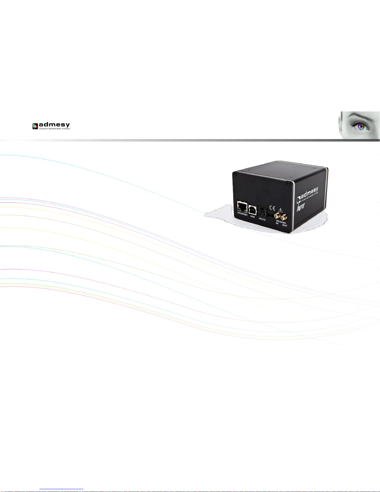
The USB B connector is used to connect the Hera to a PC/Laptop. The
Hera uses the USBTMC class protocol and can therefore be used directly
with third party provided VISA compliant libraries like NI-VISA. Hera can
be used USB powered in case the host provides enough current. Normally
every host should be able to drive 500mA, but not all of them do. Also,
USB-HUBs mostly do not supply enough current. It is therefore
recommended to use powered USB-HUBs only.
2.2 Ethernet interface
Ethernet of Hera is 100Mbit and is 10Mbit/GigE compatible. Ethernet can
be used in the same way as USB. All commands have the same format.
Ethernet is preferred over USB in situations where the distance between
device and a PC are more than 5 meters.
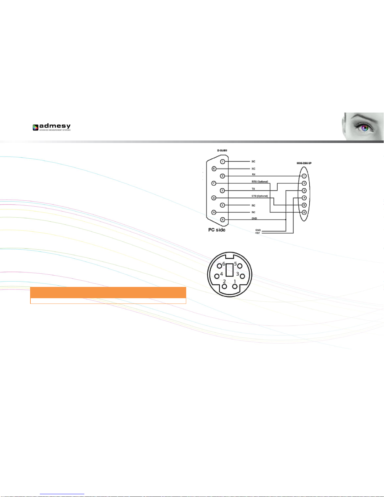
2.3 RS232 interface
RS232 is provided to connect the Hera to any host that doesn't provide
USB or Ethernet or for which no USBTMC drivers exist. Using RS232, the
functions that generate a lot of data (spectrum) are still available, but the
use of it is highly discouraged due to the low speed of RS232.
Baud
rate
Data bits
Parity
Stop bits
Flow
control
Termination
character
115200¹
8
None
1
None
LF=’\n’
Table 1 RS232 port configuration.
1 Baud rate can be changed.
Fig 1 Hera RS232 connection.
Fig 2 Rear side mini-DIN-6 pin connector.
Page 5
5
2.4 Trigger in/out
The Hera has two trigger connections. One trigger output and one trigger
input. The connectors are SMA connectors. When triggering is enabled,
the trigger output line will be set to a high level once the measurement has
finished and the measurement result is available. It will stay at a high level
until the next command is carried out, but has a minimum high level of
5μs. A trigger will carry out the last send command and send the result to
the host via the selected interface. The colorimeter main application allows
external triggering in the data-logging tab. Supplied code examples show
how to use this feature in an application. The trigger output line is used to
indicate that the measurement is ready. Trigger signals should comply to
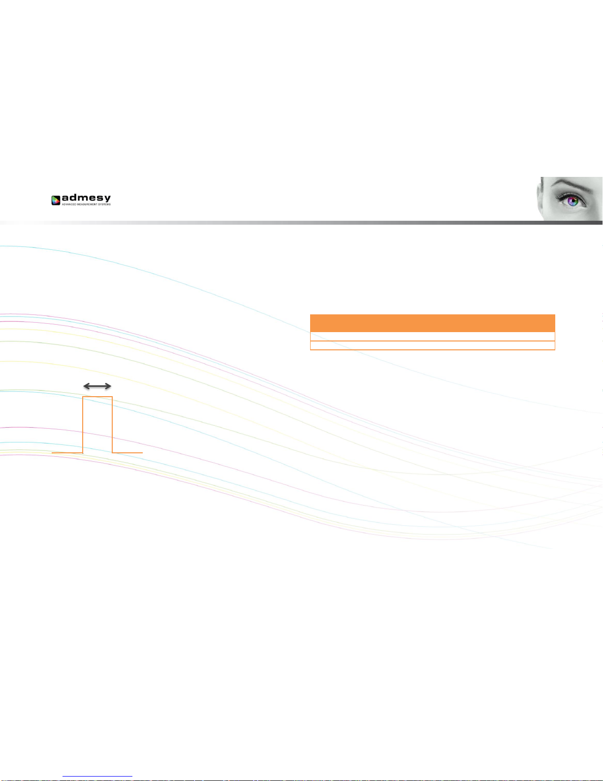
the following timing (Fig 3).
Fig 3 Trigger-in timing.
Trigger pulses arriving faster than the Hera can measure will be ignored,
but it may slowdown overall performance. Trigger pulses should not arrive
faster than the measurement takes to complete. The best way is to use the
trigger output to make sure measurement was finished.
The trigger out port provides a continuous high signal when the device is
in use. Its signal turns low when the device is not executing any
commands.
2.5 Power connections
The Hera should be connected to USB with sufficient power or using a 9V
DC power supply to the RS232 connector. When using RS232 the
spectrometer needs to be powered via the external adapter. This can be
done through the mini-DIN connector as illustrated in the RS232
connections. The unit shall be powered by a 9V DC voltage or via a
standard USB PC-port, reinforced separated from Mains, with a limited
energy of < 150VA and < 8A.
Connection
Min.
Voltage
Typ.
voltage
Max.
voltage
Max
current
USB powered
4.75 V
5.00 V
5.25 V
350mA
DC powered
8.50 V
9.00 V
15.00 V
350mA
Table 2 Power supply levels.
𝑡 > 5𝜇𝑠
Page 6
6
3 Communications protocol
3.1 USB
The Hera can be connected to any USB host and is a USBTMC compliant
device which is a standard USB class. Device drivers for this class are
available for most popular operating systems (also embedded). This
makes the Hera directly usable in popular programming languages like
NI's Labview and Labwindows but also C++, Visual basic, C#, Java etc.
The Hera has two interfaces build in, which require a different device
driver to be used.
Hera bootloader
(USB RAW device driver, Vendor ID: 0x23CF, Product ID 0x0105)
Hera01
(USBTMC device driver, Vendor ID: 0x23CF, Product ID 0x1021)
Hera02
(USBTMC device driver, Vendor ID: 0x23CF, Product ID 0x1022)
Hera01
(USBTMC device driver, Vendor ID: 0x23CF, Product ID 0x1023)
When the Hera is connected to the host, it will start the Hera firmware. As
soon as the firmware is idle to receive commands, the Power LED goes to
the ON state. The Admesy bootloader is a RAW USB device and in order
to use this device in Windows, a driver must be installed which is supplied
by Admesy. Besides upgrading to new firmware, it is also allowed to
downgrade firmware in case this is required. Note that older firmware also
may require the use of older software libraries and/or executable versions
of software. The Hera is USBTMC compliant and can be used with
libraries that contain a USBTMC compliant driver like NI-VISA. The Hera is
a USB 2.0 Full speed device. In case a USB host is detected, it is
assumed that the Hera operates only via USB.
3.2 RS232
Hera commands are equal for all interfaces. Note that for high speed
transfers it is best to use USB. When RS232 will be used, the device mode
should be set to RS232. This is done via software and stored in the device
EEPROM memory.
3.3 Ethernet
Hera commands are equal for all interfaces. When the Ethernet
connection will be used, the device mode should be set to ETH (Ethernet).
This is done via the Iliad application software: DeviceStart-up
settingsHera and stored in the device EEPROM memory. In the start-up
menu the IP address, gateway and network mask can also be changed.
Page 7
7
4 Device drivers
4.1 USB
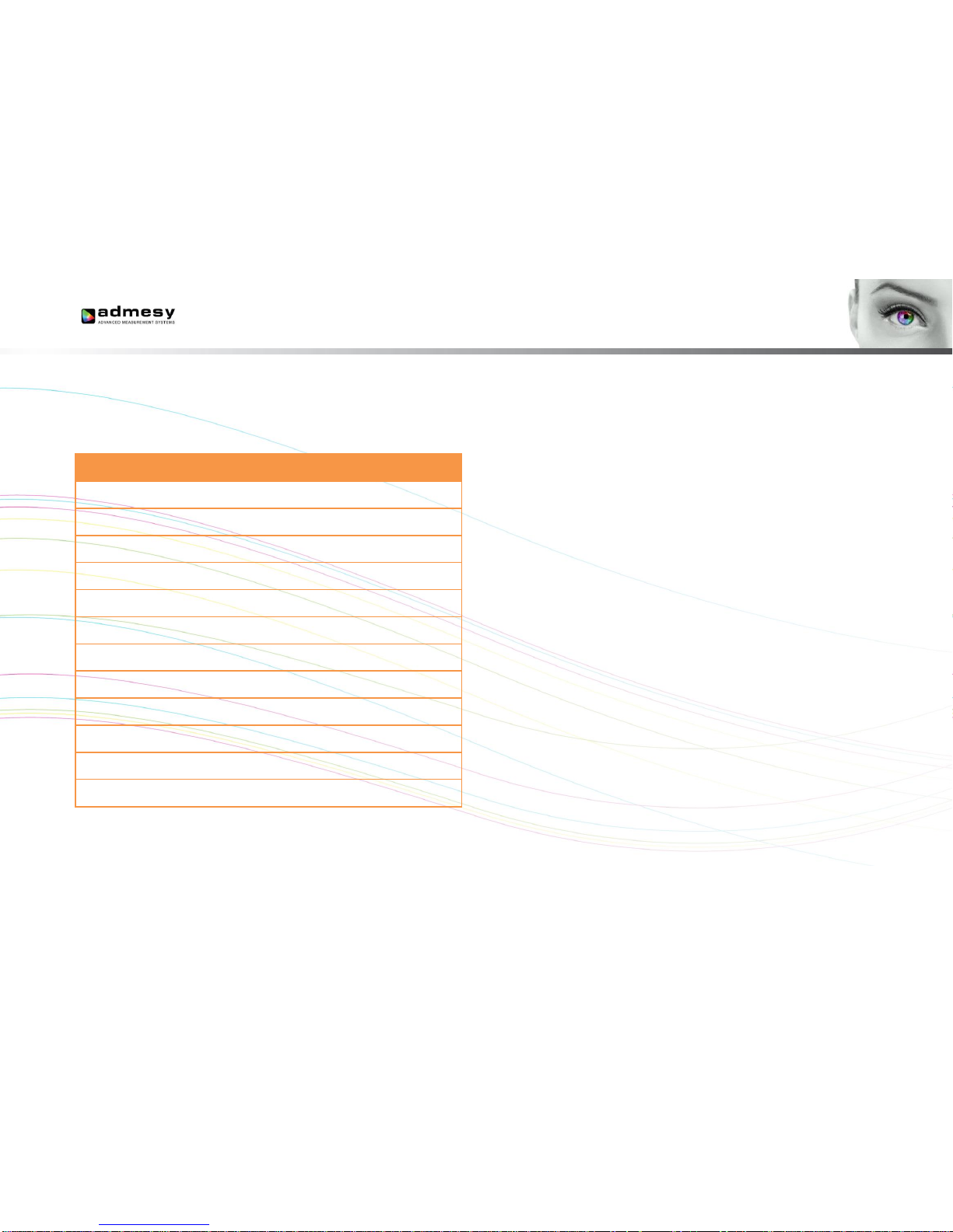
The following table shows an overview of USB support on various
operating systems.
OS
NI-VISA
Libusb
Native
kernel
Agilent
USBTMC
Windows XP 2
·
·
Not
available
Not tested¹
Windows
VISTA
·
·
Not
available
Not tested¹
Windows 7
·
·
Not
available
Not tested¹
Windows 8(.1)
·
Not tested¹
Not
available
Not tested¹
Windows 10
·
Not tested¹
Not
available
Not tested¹
Windows CE
·
Not tested¹
Not
available
Not tested¹
Apple OSX
PPC
·
Not tested¹
Not
available
Unknown
Apple OSX
Intel
·
Not tested¹
Not
available
Unknown
Linux i386
(32bit)
· · ·
·
Linux i386
(64bit)
· · ·
·
Linux ARM
Not
available
· · ·
Linux other
Not
available
· · ·
Table 3 Supported operating systems.
1 Not tested: Available, but not tested by Admesy, 2 Native Kernel: Driver included with OS.
2 Windows XP SP3 is supported: Windows official support has ended as of April 8 2014
Admesy supports all tested platforms but does not provide standard
applications on all platforms. The matrix is provided to show the possible
platforms for software development. Admesy does however provide
software examples for most of the tested platforms. Most of these
examples can be found on our support web page.
4.2 RS232
When no USB driver is available or the host system does not provide USB,
RS232 can be used as it does not require additional drivers for the Hera.
4.3 Ethernet
No special drivers are needed for Ethernet operation. The Hera can be
directly addressed through a TCP/IP socket on port 10000. In case
firewalls are used, the TCP/IP port needs to be opened.
Page 8
8
5 Command set description
5.1 Commands
The functions of the Hera can be best described via the following
categories.
System commands
Configuration commands
Measurement commands
User EEPROM commands
The Hera uses SCPI like commands for control and measurement. These
are ASCII based commands and follow specific rules regarding syntax.
Although the Hera uses SCPI like commands, they deviate from the SCPI
standard.
5.2 Command structure
Every command starts with a colon “:”, which identifies the root of the
command tree. Each further keyword is also separated by a colon. In case
parameters need to be specified, the last keyword and parameters are
separated by a single space character. In case more than one parameter
needs to be specified, the parameters need to be separated by a comma.
The command tables show commands in long and short format. The short
format is specified by upper case characters. It is allowed to use long and
short format or a mixed format. Optional keywords are shown between
brackets [...]. Commands are not case sensitive, so it is allowed to use
both or a mix of upper and lower case. The command structure is valid for
all communication interfaces of the Hera. It is recommended to terminate a
command by a newline character “\n”.
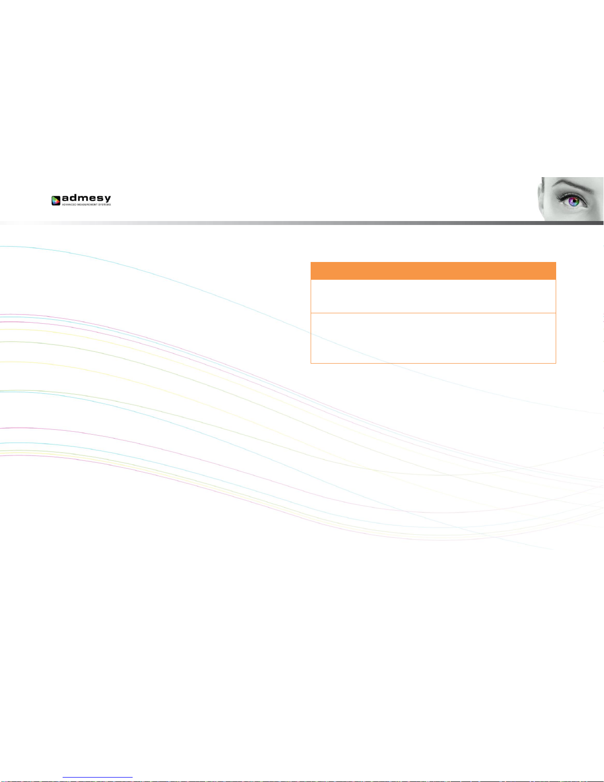
Command table
Valid command
syntax examples
Notes
:SENSe: INT 50000
:sens:int 500000
:sense:int 500000
:SENS:INT 500000
:SENSE:INT 500000
Sets the integration
time of the Hera
:MEASure:XYZ
:measure:XYZ
:measure:xyz
:meas:XYZ
:MEASure:XYZ
The measure
commands use the
averaging and
integration time
parameters that have
to be set first
Table 4 Example commands.
Page 9
9
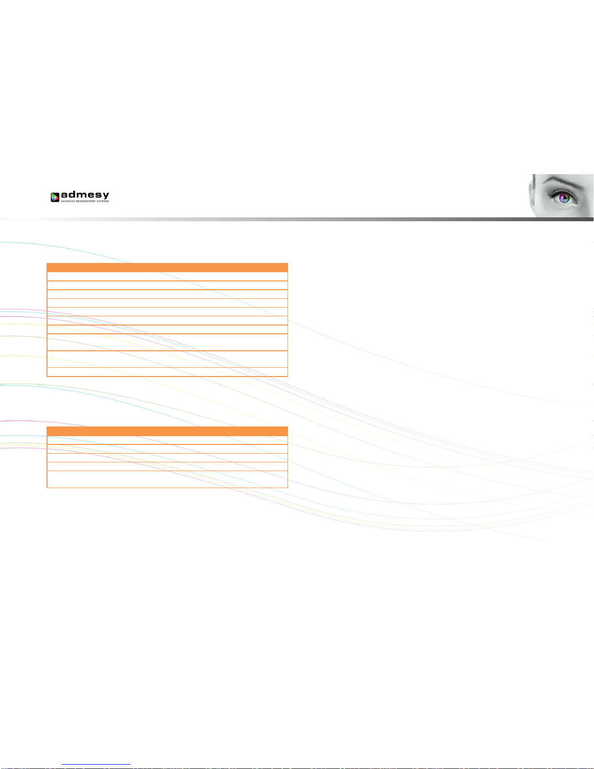
5.3 System commands
The following commands can be used to control the Hera or read back
information.
Command syntax
Parameters
Purpose
:*CLS
None
Clear status
:*IDN?
None
Identification query
:*RST
None
Reset Command
:*STB?
None
Read Status Byte query
:*TST
None
Self-test query
:*FWD?
None
Firmware date query
:*FWT?
None
Firmware time query
:SYSTem:VERSion?
None
Get system version
information
:SYSTem:ERRor?
None
Retrieve the last occurred
error
:SYSTem:ERRor:NEXT?
None
Retrieve previous errors
Table 5 System commands.
The Status byte can be used to retrieve information about the status of a
command or the system. Return values of the status command can be
seen in the table below.
Code
Description
0
System is idle
1
Data is available
2
Command processed
4
Data in buffer (should not occur)
8
An error occurred Use “:SYSTem:ERRor?”
to get the exact error that occurred
Table 6 Status commands.
Note: The status and error commands should not be used in standard programs. They are
not necessary when programming has been done correctly. They are available in case a
problem occurs during development. The :*RST command is also not necessary in normal
programs. It is advised to use the :SENSe and :CONF commands in case the behaviour of
the Hera needs to be changed to its default settings.
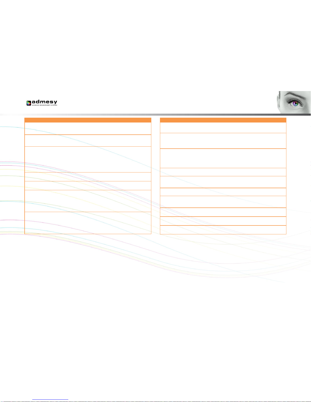
5.4 Configuration commands
Configuration commands are used to set parameters of the Hera that are
used by the measurement functions. The settings are used globally by
other measurement functions. The selected white standard is used for
dominant wavelength calculation. The integration time setting can be
varied from 2.5ms to 20s. It is specified in μs. Results from the Hera
include a clip and noise indication which indicate, whether the measured
light is too bright (clip) or too low (noise). When clipping is detected, the
resulting colour will not be correct and a lower integration time should be
chosen. When noise is detected, a larger integration time should be
chosen, see table 7 on next page.
Page 10
10
Command syntax
Parameters
Range
Purpose
:SENSe:INT
Int time
2500 –
20000000
Set integration time
(μs) of the
spectrometer
:SENSe:INT?
None
Returns the current
integration time setting
of the spectrometer
:SENSe:
INTERPOL
Interpolation
method
0 = linear
1 = cosine
2 = cubic
3 = CatmullRom
4 = Hermite
Set the spectrum
interpolation method
:SENSe:
INTERPOL?
None
Returns the current
interpolation method
:SENSe:SP:
AVERage
Averaging
1 – 200
Set the averaging for
the spectrometer
:SENSe:SP:
AVERAGE?
None
Returns the averaging
setting for the
spectrometer
:SENSe:
RESolution
Resolution
0 = 0.5nm
1 = 1nm
2 = 2.5nm
3 = 5nm
4 = 10nm
Set the spectrum
output resolution.
Interpolation is done
using the earlier
selected method
Command syntax
Parameters
Range
Purpose
:SENSe:SP:SBW
Calibration
matrix
“off” or
“user”
Set calibration matrix
for the spectrometer
:SENSe:CAL
User cal
0/1
Activate or deactivate
user spectrum
calibration
:SENSe:MODE
Mode
0 = USB
1 = Ethernet
2 = RS232
Set operating mode
(note, this one is not
stored in EEPROM).
This is useful for
triggering only
:SENSe:MODE?
None
Returns the current
setting
:SENSe:TRIG
Trigger
0 – 1
Set trigger mode (note
this is note stored in
EEPROM)
:SENSe:TRIG?
None
Returns the current
setting
:SENSe:TRIGDEL
AY
Delay
0 - 30000000
Configures a delay
before triggering in
microseconds
:SENSe:TRIGDEL
AY?
None
Reads the configured
delay before triggering
:SENSe:
AUTORANGE
Auto-range
0 – 1
Set auto-range mode
:SENSe:
AUTORANGE?
None
Returns current setting
Table 7 Sense and configuration commands.
Page 11
11
5.5 Measurement commands
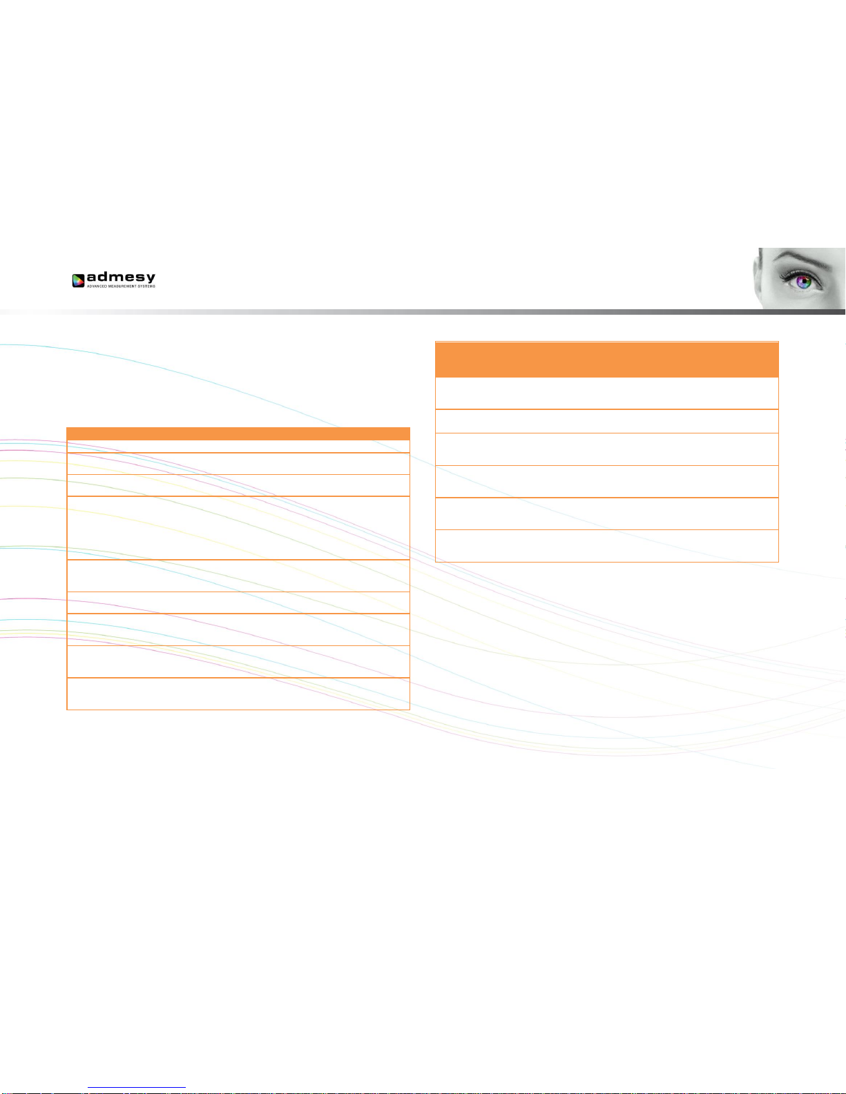
Table 8 and 9 show the measurement commands of the Hera. The
MEASure commands measure the requested values using the set
averaging and integration time and returns the result in ASCII format. The
SAMPle commands measure the requested parameters using a sample
count and delay time and return an array of data. The array contains single
float array of data.
Command syntax
Parameters
Range
Purpose
:MEASure:XYZ
None
Measure XYZ
:MEASure:Yxy
None
Measure Y and x,y
colour point
:MEASure:Yuv
None
Measure Y and u',v'
colour point
:MEASure:
SPECtrum
None
Measure the spectrum
The output is in the
selected resolution
and either uses factory
calibration or user
calibration
:MEASure:
RAWSPECtrum
None
Measures the raw
spectrum, suitable for
user calibration
:MEASure:TEMP
None
Measures the sensor
temperature
:GET:WAVE
lengths
Pixels
0
Get the wavelength
axis according to the
set resolution
:SAMPle:
SPECtrum
Samples
1 – 500
Performs High speed
sampling of a
spectrum
:SAMPle:
SPECtrum:READ
Index
1 – 500
Reads the sampled
spectrum at index.
Table 8 Measurement commands.
Special
measurement
commands
Parameters
Range
Purpose
:MEASure:CRI
Number of
test samples
8 or 15
Measure the CRI of a
light source, see
comment
:MEASure:
PEAKWL
None
Measures the peak
wavelength
:MEASure:DWL
None
Measures the
Dominant wavelength
and purity
:MEASure:ALL
CRI
0/1
Measures all
parameters with or
without CRI
:MEASure:
LEDCHAR
CRI
0/1
Measures all
parameters with or
without CRI
:MEASure:CCT
None
Measures the
correlated color
temperature
Table 9 Measurement commands.
Note: CRI calculation takes about 11ms additional time to measure a spectrum. Using the
Admesy colour DLL, this can be achieved faster.
Page 12
12
5.6 User EEPROM commands
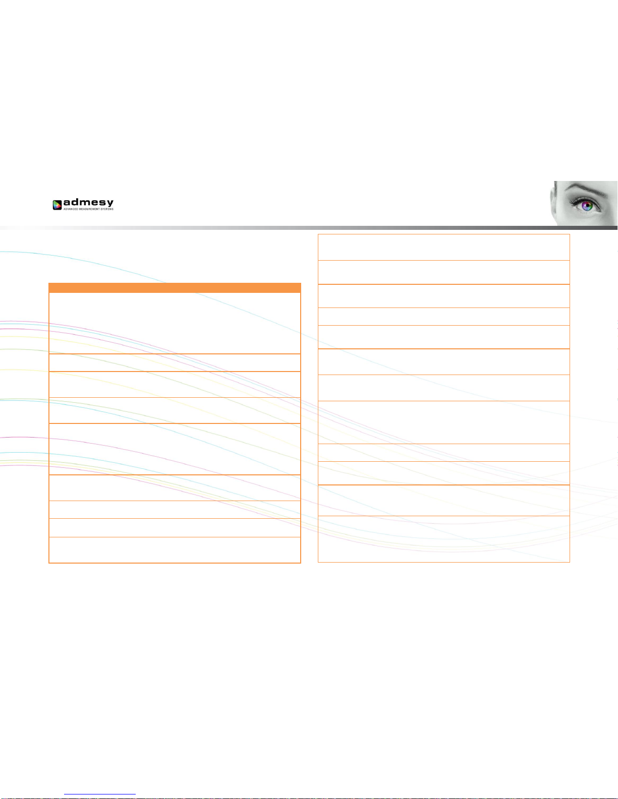
Table 10 shows the commands which can be used to store values in the
user EEPROM space. It is advised to reboot the Hera after writing new
values to the EEPROM.
Command syntax
Parameters
Range
Purpose
:EEPROM:
STARTUP:READ
None
Copies start up
conditions from
EEPROM to internal
variables.
Values can then be
read using
:SENSe:AVERage? for
example
:EEPROM:
STARTUP:WRITE
None
Copies internal
variables to EEPROM
:EEPROM:
CONFigure:MODE
Mode
0 = USB
1 = Ethernet
2 = RS232
Configures the mode
:EEPROM:
CONFigure:
MODE?
None
Reads the mode at set
in the EEPROM
:EEPROM:
CONFigure:
BAUDRATE
Baudrate
0 = 9600
1 = 19200
2 = 38400
3 = 57600
4 = 115200
5 = 230400
Configures the RS232
baudrate in the
EEPROM
:EEPROM:
CONFigure:
BAUDRATE?
None
Read the current
RS232 baudrate from
EEPROM
:EEPROM:
CONFigure:TRIG
Trigger
0 = off
1 = on
Configures triggering
:EEPROM:
CONFigure:TRIG?
None
Reads from EEPROM
if triggering is used.
:EEPROM:
CONFigure:TRIG
DELAY
Delay
0 - 30000000
Configures a delay
before triggering in
microseconds
:EEPROM:
CONFigure:TRIG
DELAY?
None
Reads the configured
delay before triggering
:EEPROM:
CONFigure:IP
IP address
Example:
192.168.0.100
Configures the
Ethernet IP address
:EEPROM:
CONFigure:IP?
None
Reads the current IP
address from
EEPROM
:EEPROM:
CONFigure:GW
Gateway
Example:
192.168.0.1
Configures the
Ethernet gateway
:EEPROM:
CONFigure:GW?
None
Reads the current
gateway address from
EEPROM
:EEPROM:
CONFigure:MASK
Ethernet
mask
Example:
255.255.255.
0
Configures the
Ethernet mask
:EEPROM:
CONFigure:MASK
?
None
Reads the current
ethernet mask from
EEPROM
:EEPROM:
CONFigure:RES
Resolution
0 = 0.5nm
1 = 1nm
2 = 2.5nm
3 = 5nm
4 = 10nm
Configures the
resolution in EEPROM
:EEPROM:
CONFigure:RES?
None
Reads the resolution
from EEPROM
:EEPROM:
CONFigure:SPINT
Int time
1000 –
500000
Configures default
spectrometer
integration time
:EEPROM:
CONFigure:
SPINT?
None
Reads the default
spectrometer
integration time from
EEPROM
:EEPROM:
CONFigure:
SPAVG
Averaging
1 – 4000
Configures default
spectrum averaging
Page 13
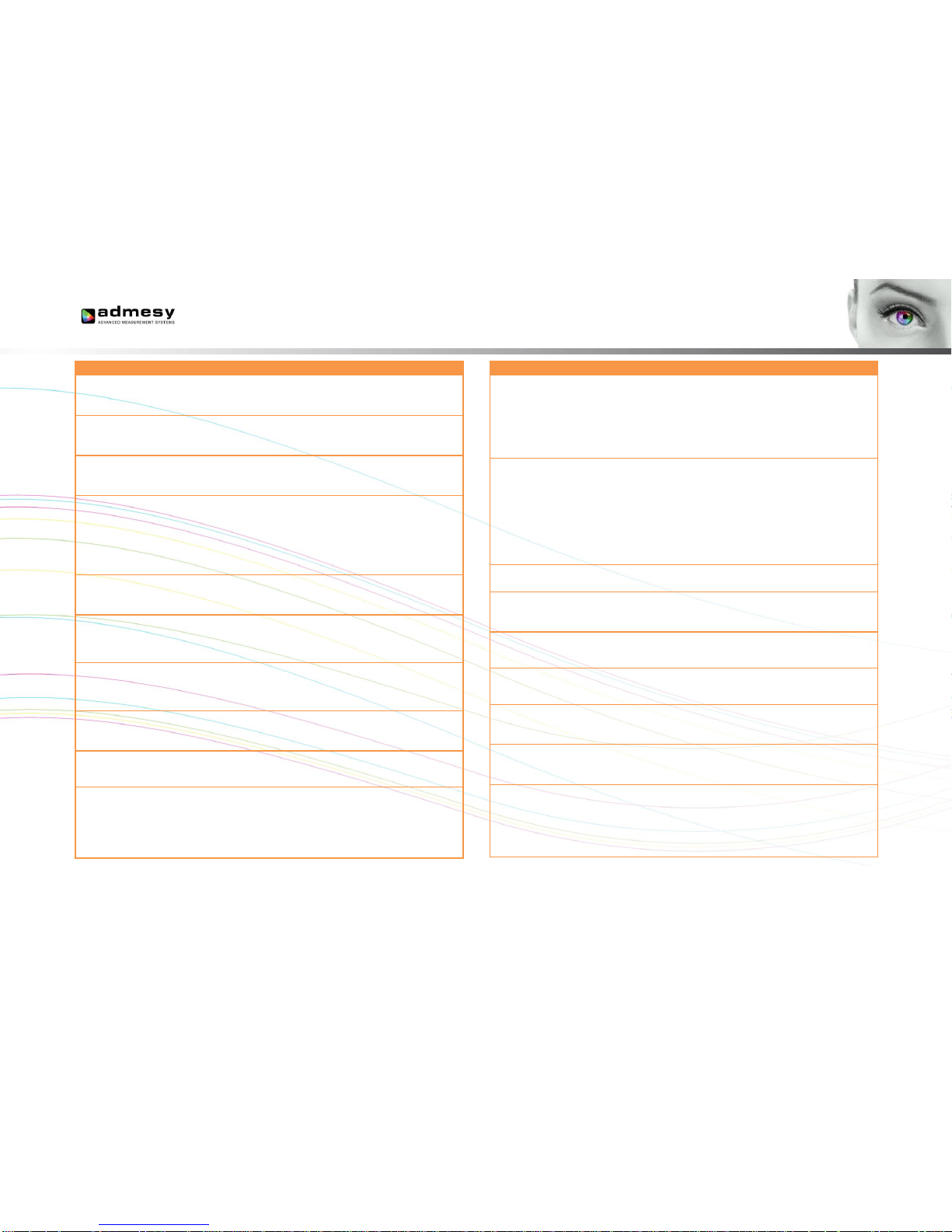
13
Command syntax
Parameters
Range
Purpose
:EEPROM:
CONFigure:
SPAVG?
None
Reads the default
spectrum averaging
from EEPROM
:EEPROM:
CONFigure:
AUTORANGE
Auto-range
0 = off
1 = on
Configures
autoranging
:EEPROM:
CONFigure:
AUTORANGE?
None
Reads the current
auto-range setting from
EEPROM
:EEPROM:
CONFigure:
INTERPOL
Interpolation
0 = linear
1 = cosine
2 = cubic
3 = CatmullRom
4 = Hermite
Configures the
interpolation method to
be used
:EEPROM:
CONFigure:
INTERPOL?
None Reads the current
interpolation method
from EEPROM
:EEPROM:
CONFigure:
SPSBW
Calibration
matrix
“off” or “user”
Configures the default
spectrometer
calibration matrix to be
used
:EEPROM:
CONFigure:
SPSBW?
None
Reads the default
spectrometer
calibration matrix from
EEPROM
:EEPROM:
SPSBW:WRITE
Row,
Column
Value
0 – 2
0 – 2
single float
Writes the values of
the spectrum matrix to
Hera
:EEPROM:
SPSBW:READ
Row
Column
0 – 2
0 – 2
Reads the values of
the spectrum matrix
from Hera
:EEPROM:READ:
USERCAL
None Reads the user
calibration values
from EEPROM to
memory
Command syntax
Parameters
Range
Purpose
:EEPROM:WRITE:
USERCAL
None
Write the user
calibration values form
memory to EEPROM.
This step fixes all
values for a next
restart of the
instrument
:EEPROM:
READ:ID
None
Reads the device ID. This is
useful for use with Medusa or
any other system with multiple
units attached. The deviceID
can be used to link to a
mechanical position of the
instrument, which can then be
selected by software for a
specific task
:EEPROM:WRITE:
ID
ID number
1 – 255
Write the device ID to
EEPROM
:EEPROM:ABS:
WRITE
Index,
Parameter,
value
Write the user absolute
spectrum parameters
:EEPROM:ABS:
READ
Index,
parameter
Reads the user
absolute spectrum
parameters
:EEPROM:ABS:
FIX
None
Fixes the user absolute
spectrum parameters
in the EEPROM
:EEPROM:
CONFigure:
WHITE
White point
“D65”, “A”,
etc
Used for Dominant
wavelength
:EEPROM:
CONFigure:
WHITE?
None
Gets the currently
configured white point
:EEPROM:
READ:UNIT
None
0 Radiant
power
1 Radiance
2 Irradiance
3 Radiant
intensity
Reads the calibrated
unit as set from factory
Page 14
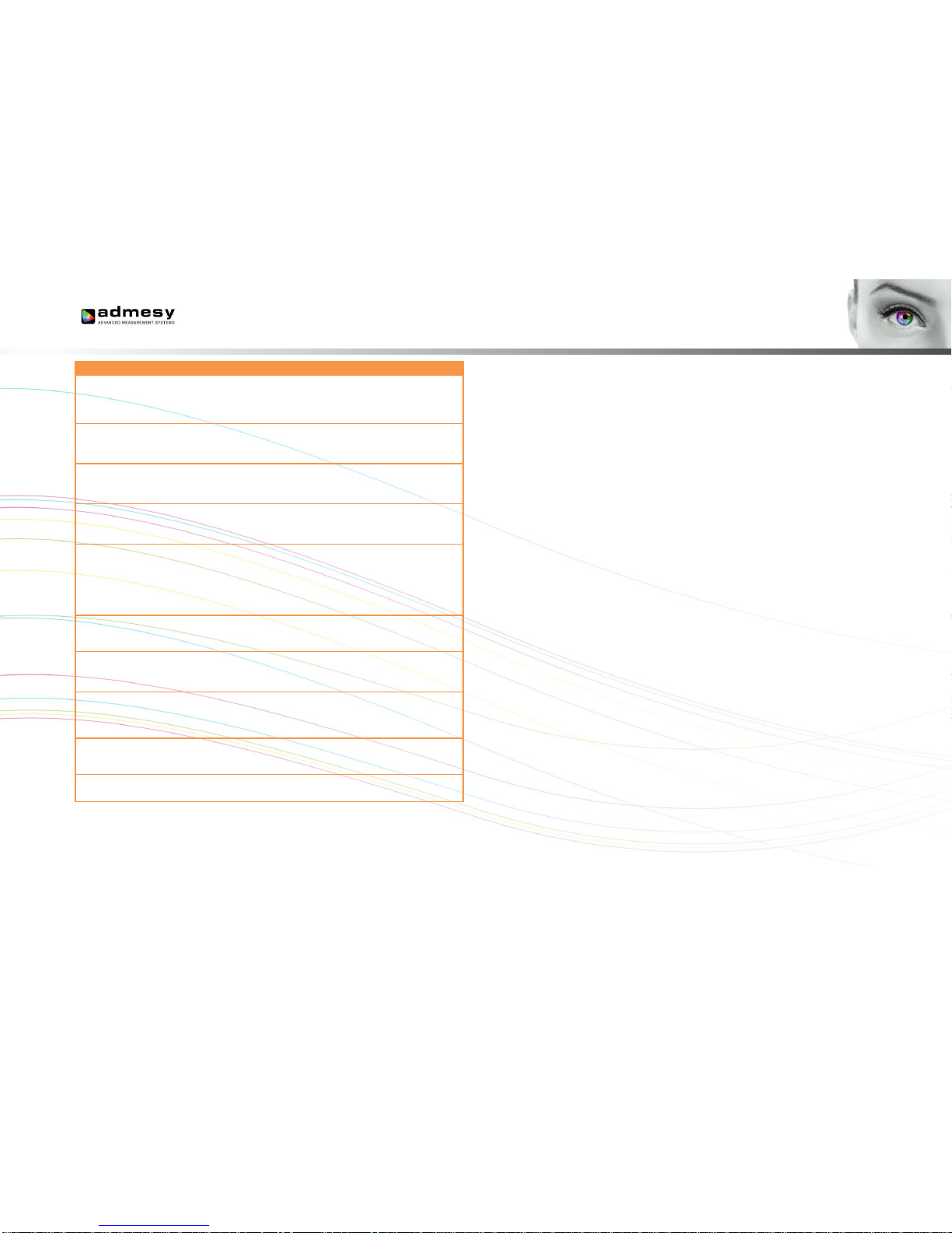
14
Command syntax
Parameters
Range
Purpose
:EEPROM:CONFi
gure:AUTO:FREQ
Frequency
(Hz)
1 – 255
Auto-range parameter:
frame frequency of the
source (display) to
measured
:EEPROM:CONFi
gure:AUTO:
FREQ?
None
Reads the set
frequency
:EEPROM:CONFi
gure:AUTO:
ADJMIN
Adjmin (%)
1 – 100
Auto-range parameter:
The minimum level to
adjust to
:EEPROM:CONFi
gure:AUTO:
ADJMIN?
None
Reads the set Adjmin
for the spectrometer
:EEPROM:CONFi
gure:MAXINT
Max int
1000 –
1000000
Maximum
spectrometer
integration time. If time
is too short, measuring
dark level may be
difficult
:EEPROM:CONFi
gure:MAXINT?
None
Query the maximum
spectrometer
integration time
:EEPROM:
CONFigure:
USERABS
Absolute
calibration
0 = factory
1 = user
Configures the
absolute calibration
mode to be used.
:EEPROM:
CONFigure:
USERABS?
None
Reads the absolute
calibration mode from
EEPROM
:EEPROM:READ:
SBWNAME
Matrix
number
Reads the name of an
XYZ matrix
:EEPROM:
READ:SN
None
Read serial number
Table 10 User EEPROM commands.
Page 15
15
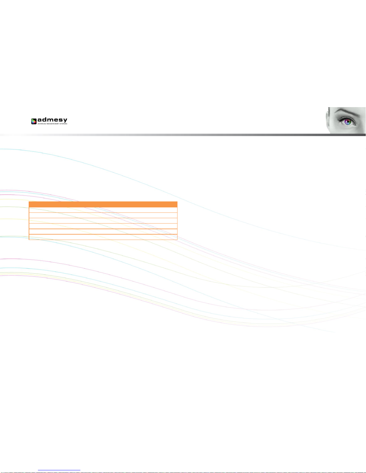
5.7 Returned results
:MEASure command return their result in ASCII formatted floating point as
shown below.
(X,Y,Z,clip,noise) → %f,%f,%f,%d,%d\n
X,Y,Z can be substituted for Y,u,v or other colour spaces. :SAMPle
command return all measurement data also in ASCII format., except the
:Sample:Y function. The first three values indicate the delta time between
samples and the clip and noise values.
MEAS command
dt
%f\n
Clip
%f\n
Noise
%f\n
Value1
%f\n
Value2
%f\n
Value3
%f\n
Table 11 Return result MEAS command.
Exceptions to the above is the :MEASure:TEMP command which only
gives back the temperature.
Page 16
16
6 Measurement example
The Hera uses default settings when the device is started. These can be
programmed by the end user so that the device starts with the same
settings each time it is connected.
Although it's possible to program all Hera devices in production
environment to start with equal settings, it is recommended to set the
averaging, integration time and SBW values in the initialization routine of
the host software.
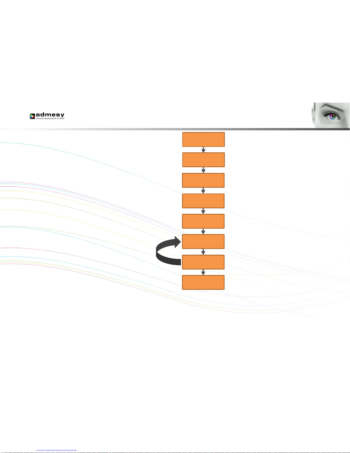
A typical measurement example of XYZ would include the following
commands as shown on the right.
Fig 4 Measurement example.
Action may be performed in a loop
Open device (VISA open, RS232 port init)
Set averaging to 1 sample
Set integration time to 16.666ms
Set calibration matrix to the first user
programmable matrix
Set auto-ranging on
Measures CIE X, Y and Z
Read the result back from device
(VISA/USBTMC read command or RS232 read)
open device
close device
:sens:aver 1
:sens:int 16666
:sens:sbw user1
:sens:autorange 1
:meas:xyz
read result
Close the device
Page 17
17
7 Autoranging
7.1 Introduction
The Hera includes an auto range function for the spectrometer sensor.
This function is useful in case the measured object shows an unknown
luminance value. In this case, the Hera will try to find the optimum setting
which is a trade-off between speed and the stability of the instrument. The
autoranging function can also be fine-tuned to reach better stability levels
by setting a few parameters. Autoranging can be controlled by 3
parameters.
Frequency : supposed to be frame frequency of the source
(display) that is measured
Adjmin : The minimum level to adjust to
Adjmin can vary between 1 and 100. Reasonable results will be achieved
when set to 40 for the spectrometer regarding the speed and the stability.
If high stability is needed, this setting must be increased (but
measurements will become slower). If a faster measurement is needed
and the stability level may be lowered a little, the value of adjmin can be
decreased. When the Hera measures in auto range mode, it can happen
that the found integration time is very low. For example when measuring
white it may be just 7ms. When this happens, the Hera will automatically
increase the averaging so that the total measurement time equals >=
(1/frequency) · averaging.
7.2 How autoranging works
The auto ranging works, by first setting a default integration time. If this
already meets the criteria for a good measurement, the measurement will
be done using that integration time. It should be clear that this is the
fastest because no adjustment will be done. In case the measured result is
either to low or too high (clip), than the Hera will adjust to a better level.
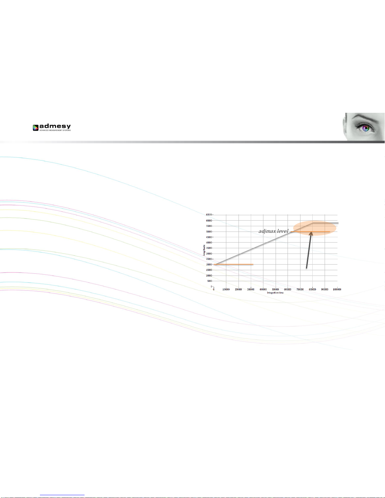
The following graph shows how levels inside the Hera work.
Fig 5 Autorange levels
When auto-ranging is set, the Hera will accept any level between “Adjmin”
and “Adjmax” as a good signal. The Adjmin level can be set by the user
through a software command, allowing some fine tuning of the stability and
the speed of the instrument.
adjmin level
adjmax level
clipping
Page 18
18
7.3 Auto-range parameters
Auto-range controls the following parameters:
Frequency: This setting must be set to the frame frequency of the
measured sample. The range is 1 to 255 Hz.
Adjmin: The adjmin parameter is very important. The higher this
level is set, the more stable the measurement becomes, but it also
slows down the measurement if set too high. That means, there is
a trade-off between speed and stability. It mainly affects the lower
grey scale levels. If these levels appear not stable, adjmin needs
to be increased. Adjmin is set from 1-100, which means 1-100% of
the Adjmax level (Adjmax is fixed by Admesy).
Maximum integration time: Although not really part of the auto-
ranging algorithm, this parameter is used when the auto-ranging
result exceeds this setting of integration time. When the grey
scales are low (grey scale 0 for example), the maximum
integration time setting can be used to allow only a maximum
measurement time. Of course this affects stability (longer
measurement is always more stable), but again this is a trade-off
for production environments to save on test time.
Averaging: The averaging will only be used if the auto-range
algorithm does calculate a averaging that is less than the set
averaging for the spectrometer sensor.
7.4 Auto-range in practice
When auto-ranging is set, the measurement settings (integration time, gain
and averaging) are automatically adjusted. An initial measurement is done
to determine the final settings of averaging and integration time, based on
the settings of frequency and adjmin.
The set integration time (1/frequency as set in the EEprom auto-range
frequency parameter) of the instrument will always be used as the first
value to try. If this setting results in a value between adjmin and adjmax,
no further actions are necessary and the speed is optimal.
When measuring a display we can measure random patterns, but mostly
known patterns are measured. Setting an integration time that is nearly
right, 1/frequency (Hz) is preferred, as it optimizes the speed for adjusting
the auto ranging settings and thus provides optimal results.
Example: a 23” TFT display (standard desktop LCD) with white at
290 cd/m² and a frame rate of 60Hz. Settings for auto ranging are:
Frequency = 60
Adjmin SP = 40
Max int SP = 3000000
These settings will provide a stable measurement on white and black.
Auto-range algorithm will adjust to measure black 0.3cm/m2 with 3000ms
integration time, resulting in ~5600ms tact time for the spectrometer
sensor.
Page 19
19
7.5 Programming Hera for auto-ranging
The Hera has start-up settings. This means that when the Hera is
connected to a PC or pattern generator, it only needs the “:meas:Yxy”
command to get luminance and colour data. All other settings can be
saved as preset and are loaded when the instrument is started. However,
it requires the right settings to be set in advance. This can be done though
the Admesy Iliad application and select DeviceStart-up settingsHera.
These setting may be optimized per display type. There are a few
categories we can define. Those are shown in the next chapters.
Display without PWM: This can be measured using almost any
settings, but the settings may be optimized for high speed. This
means, we can use a short integration time for bright images
(white for example) and decreased the maximum integration of
black to a level that gives stable results and is still fast. In this
case the frequency setting is not critical.
Display with PWM: Since the luminance will show PWM, a
measurement must at least cover 1 full frame. Taking more frames
will result in better stability. In this case the frequency setting is
apparently more critical to get a good stability.
7.6 Auto-ranging recommendations
It is recommended to apply auto ranging in case process variation is high
or in case various grey scales are measured. In cases where luminance
setting is known, it may be desirable to turn off auto-ranging to save
additional measurement / test time.
Regarding the grey scales, like a gamma measurement is performed,
speeds up the measurement significantly, when using auto-ranging in
combination with the feedback function.
There are a lot of ways to fine tune the Hera for each application. Take this
document into consideration and apply the comments correctly. By
assuming that any default setting will do, it will lead to a non-optimal
measurement results. Any measurement is application dependent. One
should consider that auto-range settings exist for the sole purpose of
optimizing each application.
Page 20
20
8 Hera measurement results
The Hera is a spectrometer that provides direct calibrated output. As from
many other mini spectrometers the Hera differs in great processing power.
Spectrum conversion to XYZ is done inside the Hera and so are all colour
space conversions, including CRI calculation. Apart from this internal
calculation, it is also possible to receive the spectral data and do the
processing on the host PC. This can be done by Admesy’s colour DLL.
The calculations performed inside the Hera are based on the same
formula’s as the DLL. Calculations done inside Hera are performed using
single precision floats and the DLL uses double precision. For formula’s
please check the user manual of the Admesy colour DLL.
9 Operating modes & triggering
The operating mode only matters in trigger mode. The mode is used to
send back results by USB, Ethernet or RS232. The modes of the Hera are:
USB mode
Ethernet mode
RS232 mode
A trigger actives only one command, for example “:meas:xyz”. This
command needs to be set first by the host. After a trigger is received, the
command will execute and the result will be presented on the selected
interface as shown above. The Hera responds to a rising edge of the
trigger signal.
Page 21
21
Admesy B.V.
Sleestraat 3
6014 CA Ittervoort
The Netherlands
T +31 (0)475 600 232
F +31 (0)475 600 316
The material in this document is subject to change. No rights can be
derived from the content of this document. All rights reserved. No part of
this document may be reproduced, stored in a database or retrieval
system, or published in any form or way, electronically, mechanically, by
print, photo print, microfilm or any other means without prior written
permission from the publisher.
Version 1.0.10 08/2017
 Loading...