

Admea OCAR User Manual
Owner’s Manual


Congratulations on your purchase, and thank you for your choosing the O Car.
Your new product is quality, high technology equipment.
With O Car, you can enjoy a wide range of music, whether it is stored on your iPhone or
received through either the included RDS tuner (supported by the “Radio” application) or
an Internet radio feed. You are guaranteed outstanding sound, with its top-of-the-line
amplifier and the “Sound” application for audio controls.
O Car lets you search for and save radio stations. You also have access to all of the other
applications on your iPhone. O Car charges your smartphone and can be used as a handsfree kit for safe calling. Its Bluetooth module includes an external microphone for uncompromising communication quality.
The removable dock can hold your iPhone horizontally or vertically or even tilt i t toward
the user’s field of vision. The O Car also coordinates with your car’s interior design, with
six color themes available by pressing the “display color” key.
To get the most from your device, learn what it can do, and prevent possible risks, we
recommend reading this manual very carefully before use.
P.01 Before Using This Product
P.01 List of Equipment Provided
P.02 Installation Precautions
P.02 Electrical Precautions
P.03 Wiring Diagram
P.03 ISO Connector
P.04 Description of Inputs and Outputs
P.04 Installing the Microphone
P.05 Installing the Head Unit
P.06 Installing the Detachable Faceplate
P.07 Identifying the Parts of the Faceplate
P.08 Inserting an iPhone
P.08 Handling the Cradle
P.09 Using the Swivel
P.09 Uninstalling the Head Unit
P.10 “Sound” Application
P.13 “Radio” Application
P.16 Bluetooth Pairing
P.16 Using Other Applications
P.16 Recommendations for Use
P.17 Specifications
P.18 Troubleshooting
P.19 Warranty Policy
Before Using This Product
O Car requires two applications to be downloaded in order to operate.
The “Radio” application is used for controlling the tuner. It can be downloaded from
the iTunes store using the keywords “Oxygen Radio” and then synced to your iPhone
through iTunes.
The “Sound” application is used for controlling the amplifier. It can be downloaded
from the iTunes store using the keywords “Oxygen Sound” and then synced to your
iPhone through iTunes.
O Car cannot work with your iPhone without these downloaded applications.
List of Equipment Provided
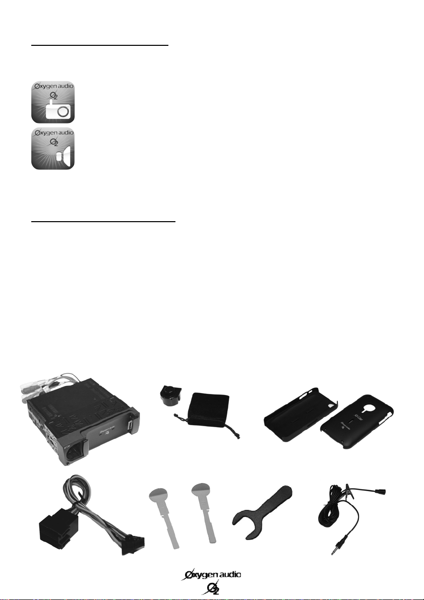
Your package contains the following equipment:
A multilingual owner’s manual
- (a) O Car in its mounting bracket (a)
- (b) A cloth carrying case containing the O Car’s detachable faceplate
- (c) Two protective covers, one for the iPhone 3G/3GS and the other for the iPhone 4
- (d) An ISO connection
- (e) A set of two keys for removing the O Car
- (f) A large-diameter key for adjusting the swivel
- (g) A wired microphone with a 3.5mm jack.
(d)
(b)
(a)
(e)
(f)
(c)
(g)
1

Installation Precautions
Installing the O Car in your vehicle requires a good understanding of your car’s electrical
system. If you are not comfortable installing it yourself, we strongly recommend contacting
an approved professional to install the O Car in your vehicle.
O Car is designed for 1DIN (182 x 53mm) installations, with a custom depth to support its frame
(about 185mm).
The electronic part of O Car was designed to operate with a continuous voltage of 12V. However, it
supports operating voltages ranging from 11V to 14.5V. No matter what, your device cannot work
with electrical systems whose voltage is above or below this range.
The O Car cannot be installed on vehicles with a different operating voltage (24-volt trucks, 6-volt
mopeds, etc.).
O Car is designed only for installation in covered vehicles, protecting it from moisture, extreme
heat, and direct exposure to the sun, all of which can damage it.
Electrical Precautions
O Car comes with a 15-amp protective fuse. It is therefore recommended that you check whether
your vehicle is equipped to draw such a current. If it cannot, you must first create the ability for
your vehicle to draw a 15-amp current before continuing.
If the fuse blows, it must be replaced with an equivalent fuse. Replacing the fuse with a higher
voltage can not only destroy your device, but also seriously impact your vehicle’s entire electrical
system.
A blown fuse rarely happens on its own. It is therefore strongly recommended that you check your
entire system before replacing it.
2
Wiring Diagram
(2)
(3)
(4)
(8)
(9)
(6)
(7)
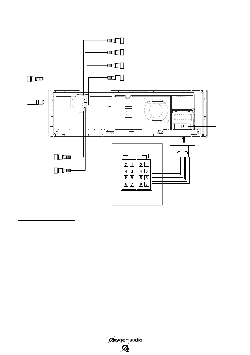
ISO Connector (1)
A1. Not connected
A2. Not connected
A3. Not connected
A4. + permanent (yellow)
A5. Power antenna control (blue)
A6. Not connected
A7. + Switched (red)
A8. Ground (black)
(5)
A
B
ISO Connector
B1. Right rear speaker + (purple)
B2. Right rear speaker - (purple/black)
B3. Right front speaker + (gray)
B4. Right front speaker - (gray/black)
B5. Left front speaker + (white)
B6. Left front speaker - (white/black)
B7. Left rear speaker + (green)
B8. Left rear speaker - (green/black)
(1)
(10)
Depending on your vehicle’s ISO mounting, you may have to reverse the position A4 (yellow) and
A7 (red) wires using “rapid” connectors so as not to lose the memory on your device.
3

Despite the consistency of ISO connectors, there are variations in the system whereby some connector positions are used for functions other than those initially assigned by the ISO standard. Also,
it is recommended to pay attention to the use of the wire in position A5.
Although it was originally used for powering a power antenna or an amplifier, it is sometimes also
used for other functions specific to the original car radio. In this case, we recommend looking for
another ground or electrical current on the car portion of the ISO connector in this position and
checking that it really corresponds to a power antenna control.
To avoid damaging your device, if you are uncertain about anything, we recommend disconnecting
the wire using the current connector and insulating both sides using insulating tape.
Description of Inputs and Outputs
(2) Gray wire to yellow connector: RCA video output for connecting up to two additional screens
whose input impedance modulus should not be less than 75 ohms.
(3) Gray wire to green connector: RCA subwoofer output for the use of a specific amplifier for the
base channel.
(4) Gray wire to red connector: “Right front” RCA output for connecting to an optional amplifier’s
dedicated channel.
(5) Gray wire to white connector: “Left front” RCA output for connecting to an optional amplifier’s
dedicated channel.
(6) Brown wire to white connector: “Left rear” RCA output for connecting to an optional
amplifier’s dedicated channel.
(7) Brown wire to red connector: “Right rear” RCA output for connecting to an optional amplifier’s
dedicated channel.
(8) 3.5mm jack connector: Microphone input. For connecting the supplied microphone.
(9) Antenna connector: For connecting to the vehicle’s antenna.
(10) 15-amp fuse
Installing the Microphone (required for hands-free functionality)
For better communication quality, we recommend positioning your microphone at the top corner of
your windshield on the driver’s side (toward the driver).
During telephone communications, we recommend closing the windows of your vehicle to prevent
the movement of the air from disturbing the microphone.
Obviously, we recommend using caution during telephone calls and keeping your eyes on the road.
4
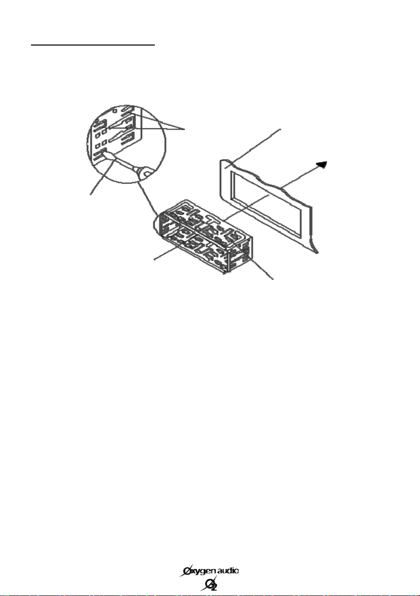
Installing the Head Unit
Using small metal inserts on each side of the bracket, remove the O Car from its housing. Next,
insert the mounting bracket into the slot on your dashboard, as described below.
Mounting bracket
Using a screwdriver, bend
the small metal tabs around
the bracket in order to firmly
secure it to the dashboard.
Make the necessary elect rical connections (see pages 3 & 4), and then insert your device into its
mounting bracket until the metal inserts go back to their original positions on the body of the car
radio. You will hear a click on each side when you car radio is properly in place.
Dashboard
Mounting tabs
5
 Loading...