

Admag AXW900G, AXW600G, AXW700G, AXW800G, AXW10LG Installation Manual
...
User’s
Manual
ADMAG TI Series
AXW Magnetic Flowmeter
[Size: 500 to 1800 mm (20 to 72 in.)]
Installation Manual
Integral Flowmeter
(AXW###G)
Remote Transmitter
(AXFA11G)
This manual outlines the basic guidelines for installation and
wiring procedures. For the items which are not covered in this
manual, see the user’s manuals and the general speci ca-
tions as listed in Table 1.1.
Remote Sensor
(AXW###G, AXW###W)
Remote Transmitter
(AXW4A)
IM 01E25A01-01EN
Contents
1. Introduction
1.1 For Safe Use of Product ................................................3
1.2 Warranty .........................................................................6
1.3 Combination for Remote Sensor and Remote
Transmitter .....................................................................6
2. Receiving and Storage
2.1 Model and Speci cations Check ...................................8
2.2 Storage Precautions ......................................................8
3. Installation
3.1 Piping Design Precautions ............................................9
3.2 Handling Precautions .................................................. 12
3.2.1 General Precautions ...................................... 12
3.2.2 Flowmeter Piping ........................................... 13
3.3 Integral Flowmeter and Remote Sensor Installation .. 13
3.4 Remote Transmitter Installation .................................. 19
3.4.1 Installation Location ....................................... 19
3.4.2 Mounting of AXW4A Transmitter ................... 19
3.4.3 Mounting of AXFA11 Transmitter ................... 19
3.5 Changing Direction of Electrical Connection .............. 20
3.5.1 Integral Flowmeter ......................................... 20
3.5.2 Remote Sensor ............................................. 21
3.6 Changing Direction of Display Unit ............................. 22
4. Wiring
4.1 Wiring Precautions ...................................................... 23
4.2 Cables ......................................................................... 24
4.3 Electrical Connections ................................................ 25
4.4 Connecting to External Instruments of Integral
Flowmeter and Remote Transmitter ........................... 29
4.5 Connecting to Remote Sensor and Remote
Transmitter (Sensor Side) ........................................... 34
4.6 Input and Output ......................................................... 37
5. Basic Operating Procedures
5.1 Operation by Display unit ............................................ 40
5.2 Display and Basic Con guration ................................. 40
5.3 Display Mode and Setting Mode ................................. 43
5.4 Parameter Setting from Display Panel ....................... 44
5.5 microSD Card Setting ................................................. 45
5.6 BRAIN Con guration Tool ........................................... 45
5.7 HART Con guration Tool ............................................ 46
5.8 Modbus Con guration Tool ......................................... 47
6. Operation
6.1 Pre-operation Zero Adjustment ................................... 48
6.2 Zero Adjustment from Display Unit ............................. 48
6.3 Hardware Switch Setting ............................................ 49
7. Errors and Countermeasures (Display unit)
1
2
3
4
5
6
7
IM 01E25A01-01EN
2nd Edition
<1. Introduction>
1. Introduction
This manual provides the basic guidelines for installation,
wiring procedures and basic operation of ADMAG TI
(Total Insight) Series AXW magnetic owmeters (size:
500 to 1800 mm (20 to 72 in.)) with BRAIN, HART and
Modbus protocol.
For the items which are not covered in this manual,
read the applicable user’s manuals and general
specications as listed in Table 1.1. These documents
can be downloaded from the website of YOKOGAWA. To
ensure correct use of the instrument, read these manuals
thoroughly and fully understand how to operate the
instrument before operating it. For method of checking
the model and specications, read Chapter 2 and general
specications as listed in Table 1.1.
Website address: http://www.yokogawa.com/d/doc/
These manuals can be downloaded from the website
of YOKOGAWA or purchased from the YOKOGAWA
representatives.
Table 1.1 Manual and General Specications List
Model Document Title Document No.
ADMAG TI Series
AXW###G
AXW###W
AXW4A
AX01C
AXFA11G
AXFC
AXG/AXW Magnetic Flowmeter
Read Me First
ADMAG TI Series
AXG/AXW Magnetic Flowmeter
Safety Manual
ADMAG TI Series
AXW Magnetic Flowmeter
[Size: 500 to 1800 mm (20 to 72 in.)]
Installation Manual
ADMAG TI Series
AXW Magnetic Flowmeter
[Size: 25 to 1800 mm (1 to 72 in.)]
Maintenance Manual
ADMAG TI Series
AXW Magnetic Flowmeter
BRAIN Communication Type
ADMAG TI Series
AXW Magnetic Flowmeter
HART Communication Type
ADMAG TI Series
AXG, AXW Magnetic Flowmeter
Modbus Communication Type
ADMAG TI Series
AXW Magnetic Flowmeter
[Size: 500 to 1800 mm (20 to 72 in.)]
General Specications
AXF Series
Magnetic Flowmeter
Read Me First
AXFA11G Remote Converter
[Hardware Edition/Software Edition]
AXFA11G Remote Converter
General Specications
IM 01E21A21-01Z1
IM 01E21A21-02EN
IM 01E25A01-01EN
(this manual)
IM 01E24A01-02EN
IM 01E24A02-01EN
IM 01E24A02-02EN
IM 01E21A02-05EN
GS 01E25D11-01EN
IM 01E20A21-01Z1
IM 01E20C01-01E
GS 01E20C01-01E
Precautions Related to the Protection,
The following safety symbol marks are used in this
manual and instrument.
The following symbols are used in the Instrument and the
manual to indicate the accompanying safety precautions:
NOTE
When describing the model name like AXW###G in this
manual, “###” means any of the following.
500, 600, 700, 800, 900, 10L, 11L, 12L, 13L, 14L, 15L,
16L, 18L
Safety, and Alteration of the Instrument
WARNING
A WARNING sign denotes a hazard. It calls attention to
procedure, practice, condition or the like, which, if not
correctly performed or adhered to, could result in injury
or death of personnel.
CAUTION
A CAUTION sign denotes a hazard. It calls attention
to procedure, practice, condition or the like, which, if
not correctly performed or adhered to, could result in
damage to or destruction of part or all of the product.
IMPORTANT
An IMPORTANT sign denotes that attention is required
to avoid damage to the instrument or system failure.
NOTE
A NOTE sign denotes information necessary for
essential understanding of operation and features.
Protective grounding terminal
Functional grounding terminal (This terminal should
not be used as a protective grounding terminal.)
Alternating current
Direct current
Caution
This symbol indicates that the operator must refer to
an explanation in the user’s manual in order to avoid
the risk of injury or death of personnel or damage to
the instrument.
1
1
Introduction
All Rights Reserved, Copyright © 2017, Yokogawa Electric Corporation
IM 01E25A01-01EN2nd Edition: Oct. 2018 (KP)

<1. Introduction>
2
• For the protection and safe use of the instrument and
the system in which this instrument is incorporated,
be sure to follow the instructions and precautions
on safety that is stated in this manual whenever
you handle the instrument. Take special note that if
you handle the instrument in a manner that violated
these instructions, the protection functionality of the
instrument may be damaged or impaired. In such
cases, YOKOGAWA does not guarantee the quality,
performance, function, and safety of instrument.
• When installing protection and/or safety as lighting
protection devices and equipment for the instrument
and control system or designing or installing separate
protection and/or safety circuits for fool-proof design
and fail-safe design of the processes and lines that
use the instrument and the control system, the user
should implement these using additional devices and
equipment.
• Should use the parts specied by YOKOGAWA when
replacing. Please contact YOKOGAWA’s service
ofce for fuse replacement.
• This instrument is not designed or manufactured
to be used in critical applications that directly affect
or threaten human lives. Such applications include
nuclear power equipment, devices using radioactivity,
railway facilities, aviation equipment, air navigation
facilities, aviation facilities, and medical equipment. If
so used, it is the user’s responsibility to include in the
system additional equipment and devices that ensure
personnel safety.
• Do not modify this instrument.
• YOKOGAWA will not be liable for malfunctions or
damage resulting from any modication made to this
instrument by the customer.
• The instrument should be disposed of in accordance
with local and national legislation/regulations.
Regarding This User’s Manual
• This manual should be provided to the end user.
• The contents of this manual are subject to change
without prior notice.
• All rights reserved. No part of this manual may be
reproduced in any form without YOKOGAWA’s written
permission.
• YOKOGAWA makes no warranty of any kind with
regard to this manual, including, but not limited to,
implied warranty of merchantability and tness for a
particular purpose.
• If any question arises or errors are found, or if any
information is missing from this manual, inform the
nearest YOKOGAWA sales ofce.
• The specications covered by this manual are limited
to those for the standard type under the specied
model number break-down and do not cover custom-
made instruments.
• Note that changes in the specications, construction,
or component parts of the instrument may not
immediately be reected in this manual at the time
of change, provided that postponement of revisions
will not cause difculty to the user from a functional or
performance standpoint.
• This manual is intended for the following personnel;
Engineers responsible for installation and wiring of the
instrument.
Personnel responsible for normal daily operation of
the instrument.
• To ensure correct use, read this manual and
the applicable manuals as listed in Table 1.1
thoroughly before starting operation. Read the
general specications as listed in Table 1.1 for its
specication.
Trademarks:
• HART is a registered trademark of FieldComm Group.
• Modbus is a registered trademark of AEG Schneider.
• All the brands or names of Yokogawa Electric’s
products used in this manual are either trademarks
or registered trademarks of Yokogawa Electric
Corporation.
• All other company and product names mentioned
in this manual are trade names, trademarks or
registered trademarks of their respective companies.
• In this manual, trademarks or registered trademarks
are not marked with ™ or
®
.
IM 01E25A01-01EN
<1. Introduction>
3
1.1 For Safe Use of Product
For the protection and safe use of the instrument and
the system in which this instrument is incorporated, be
sure to follow the instructions and precautions on safety
that is stated in this manual whenever you handle the
instrument. Take special note that if you handle the
instrument in a manner that violated these instructions,
the protection functionality of the instrument may be
damaged or impaired. In such cases, YOKOGAWA
shall not be liable for any indirect or consequential loss
incurred by either using or not being able to use the
Instrument.
(1) General
• This instrument conforms to EN61326-1, EN61326-23, EN61000-3-2, and EN61000-3-3 (EMC standard).
• This instrument is an EN61326-1 (EMC standard),
Class A (for use in commercial, industrial, or business
environments).
• This instrument (General-purpose type) is complied
with IP66 and IP67 in the IP Protection Grade.
YOKOGAWA assumes no liability for the customer’s
failure to comply with these requirements.
• This instrument (Submersible type) is complied with
IP68 in the IP Protection Grade.
YOKOGAWA assumes no liability for the customer’s
failure to comply with these requirements.
• This instrument is designed for indoor and outdoor
use.
CAUTION
This instrument is a Class A instrument in the
EN61326-1(EMC standard). Operation of this
instrument in a residential area may cause radio
interference, in which case the user is required to take
appropriate measures to correct the interference.
IMPORTANT
The minimum ambient temperature is limited by the
minimum uid temperature of the sensor (the lining).
For more information, read the applicable general
specications as listed in Table 1.1.
The owmeter may be used in an ambient humidity
where the relative humidity ranges from 0 to 100%.
However, avoid long-term continuous operation at
relative humidity above 95%.
WARNING
• Purpose of use
This instrument is the Magnetic Flowmeter for use of
measuring the liquid ow. Do not use this instrument
for other purposes.
WARNING
• Installation, wiring and maintenance of the magnetic
owmeter must be performed by expert engineer
or skilled personnel. No operator shall be permitted
to perform procedures relating to installation, wiring
and maintenance.
• Wiring work should be done adequate wire, sleeve
crimp and torque force. Use terminal with insulating
cover for the power supply wiring and protective
grounding wiring. Do not pull the wires too much
strongly in order to prevent electric shocks caused
by their damage.
• Do not open the cover in wet weather or humid
environment. When the cover is open, stated
enclosure protection is not applicable.
• Ensure that the power supply is off in order to
prevent electric shocks.
• When opening the cover, wait for more than 20
minutes after turning off the power. Only expert
engineer or skilled personnel are permitted to open
the cover.
• When opening and closing the transmitter cover, be
sure to handle the transmitter cover carefully so that
there are no damage and foreign matter adhesion at
its threads and O-ring.
• This instrument employs the parts which are
affected by a function damage caused by static
electricity. Thus, you should do the antistatic work
using an anti-static wrist band for it and be careful
to avoid touching each electrical parts and circuitry
directly.
• When connecting the wiring, check that the supply
voltage is within the range of the voltage specied
for this instrument before connecting the power
cable. In addition, check that no voltage is applied to
the power cable before connecting the wiring.
• To prevent electric shocks, ensure the electrical
wiring cover is completely attached after the wiring
work.
• To prevent electric shocks, do not impress over
rated voltage to each input/output terminals.
• If there is any unused electrical connection, use
the blanking plug to cover which comes with this
instrument or which is supplied by YOKOGAWA.
The blanking plug should be fastened into the
unused electrical connection without any mistake. If
not, stated enclosure protection is not applicable.
1
Introduction
IM 01E25A01-01EN
<1. Introduction>
4
(2) Installation
WARNING
• The magnetic owmeter is a heavy instrument.
Be careful that no damage is caused personnel
through accidentally dropping it, or by exerting
excessive force on the magnetic owmeter. When
moving the magnetic owmeter, always use a trolley
and have at least two people carry it.
• Do not apply excessive weight, for example, a
person stepping on the magnetic owmeter.
• The magnetic owmeter must be installed within the
specication conditions.
• Connect the Protective Grounding Terminal
Ensure to connect the protective grounding to
prevent electric shock before turning on the power.
• Do Not Impair the Protective Grounding
Never cut off the internal or external protective
grounding wire or disconnect the wiring of the
protective grounding terminal. Doing so invalidates
the protective functions of the instrument and poses
a potential shock hazard.
• Do Not Operate with Defective Protective
Grounding
Do not operate the instrument if the protective
grounding might be defective. Also, ensure to check
them before operation.
• Do Not Operate in an Explosive Atmosphere
Do not operate the instrument in the presence
of ammable gas, vapors, or combustible dust.
Operation in such an environment constitutes a
safety hazard. Prolonged use in a highly dense
corrosive gas (H
malfunction.
• Ground the Instrument before Making External
Connections
Connect the protective grounding before connecting
to the item under measurement or control unit.
• Damage to the Protection
Operating the instrument in a manner neither
described in this manual nor the manuals as listed in
Table 1.1 may damage the instrument’s protection.
• The owmeter should be installed away from
electrical motors, transformers, and other power
sources in order to avoid interference with
measurement.
• Install an external switch or circuit breaker as a
means to turn the power off (capacitance: 15A,
conforming to IEC60947-1 and IEC60947-3).
Locate this switch either near the instrument or
in other places facilitating easy operation. Afx a
"Power Off Equipment" label to this external switch
or circuit breaker.
• All procedures relating to installation must comply
with the electrical code of the country where it is
used.
S, SOx, etc.) will cause a
2
(3) Wiring
WARNING
• In cases where the ambient temperature exceeds
50°C, use external heat resistant wiring with a
maximum allowable temperature of 70°C or above.
• When wiring the conduits, pass the conduit through
the wiring connection port, and utilize the waterproof
gland to prevent water from owing in. Install a drain
valve at the low end of the vertical pipe, and open
the valve regularly.
• Do not connect cables outdoors in wet weather in
order to prevent damage from condensation and to
protect the insulation, e.g. inside the terminal box of
the owmeter.
• The transmitter case should be removed by
YOKOGAWA’s qualied personnel only. Opening
the transmitter case is dangerous, because some
areas inside the instrument have high voltages.
• The protective grounding must be connected
securely at the terminal with the
danger to personnel.
mark to avoid
(4) Operation
WARNING
Be sure to enable the write protect function to prevent
the overwriting of parameters after nishing parameter
setting.
In rare cases, the infra-red switches may respond
unexpectedly in such conditions as sticking ball of water
or extraneous substances on the surface of display
panel glass according to the principle of infra-red switch
operation. Its probability rises in such cases as sticking
rain water by storm or other similar situation and
washing up work near owmeter installation place.
Blinking light from a ashlight etc. to the infra-red
switches may result in the malfunction.
Read Section 6.3 for the hardware write protect
function, and the user's manual of applicable
communication type as listed in Table 1.1 for the
software write protect function.
IM 01E25A01-01EN
<1. Introduction>
5
(5) Maintenance
WARNING
• When maintaining the instrument, read the
maintenance manual as listed in Table 1.1. Do not
perform the maintenance that is not described in the
manual. If necessary, contact YOKOGAWA.
• When the magnetic owmeter is processing hot
uids, the instrument itself may become extremely
hot. Take sufcient care not to get burnt.
• Where the uid being processed is a toxic
substance, avoid contact with the uid and avoid
inhaling any residual gas, even after the instrument
has been taken off the piping line for maintenance
and so forth.
• If dirt, dust or other substances surfaces on the
glass of display cover, wipe them clean with a soft
dry cloth.
• Maintenance of this owmeter should be
implemented in a maintenance service shop where
the necessity tools and environment condition are
provided.
The necessity of this environmental condition is that
ambient temperature is 5 to 40°C (the maximum
relative humidity is 80 % for temperature 5 to 31°C,
and decreasing linearly to 50 % relative humidity at
40°C).
(6) Modication
• Do not modify this instrument.
• YOKOGAWA will not be liable for malfunctions or
damage resulting from any modication made to this
instrument by the customer.
(9) microSD Card
IMPORTANT
• Do not store or use the microSD card in places
with static electricity, near electrically charged
objects, or where electrical noise is present. Doing
so can result in shock or damage.
• Do not disassemble or modify the microSD card.
• Do not physically shock, bend, or pinch the
microSD card.
• During reading/writing of data, do not turn off the
power, apply vibration or shock, or pull out the
card. Data can corrupt or be permanently lost.
• Use only micro SD cards sold by YOKOGAWA.
Operation cannot be guaranteed when other cards
are used.
• When inserting the microSD card into the
instrument, make sure to orient the microSD card
correctly (face up or down) and insert it securely. If
not inserted correctly, the microSD card will not be
recognized by the instrument.
• Do not touch the microSD card with wet hands.
• Do not use the microSD card if it is dusty or dirty.
• The microSD card comes formatted. If you want
to format the microSD card, use the instrument's
Format function.
• YOKOGAWA provides no warranty for damage
to, or loss of data recorded on the microSD card,
regardless of the cause of such damage or loss.
We recommend making backup copies of your
data.
1
Introduction
(7) Product Disposal
The instrument should be disposed of in accordance
with local and national legislation/regulations.
(8) Power Supply
Ensure that the source voltage matches the voltage of
the power supply before turning on the power.
Power Supply Code 1:
• AC Type:
Rated Power Supply: 100 to 240 V AC, 50/60 Hz
• DC Type:
Rated Power Supply: 100 to 120 V DC
Power Supply Code 2:
• AC Type:
Rated Power Supply: 24 V AC, 50/60 Hz
• DC Type:
Rated Power Supply: 24 V DC
Power Consumption: 13 W
Note: For AXFA11, read the applicable user’s manual as
listed in Table 1.1.
IM 01E25A01-01EN
<1. Introduction>
6
1.2 Warranty
• The warranty shall cover the period noted on the
quotation presented to the purchaser at the time of
purchase. Problems occurred during the warranty
period shall basically be repaired free of charge.
• In case of problems, the customer should contact
the YOKOGAWA representative from which
the instrument was purchased, or the nearest
YOKOGAWA ofce.
• If a problem arises with this instrument, please inform
us of the nature of the problem and the circumstances
under which it developed, including the model
specication and serial number. Any diagrams,
data and other information you can include in your
communication will also be helpful.
• Responsible party for repair cost for the problems
shall be determined by YOKOGAWA based on our
investigation.
• The Purchaser shall bear the responsibility for
repair costs, even during the warranty period, if the
malfunction is due to:
- Improper and/or inadequate maintenance by the
purchaser.
- Failure or damage due to improper handling, use
or storage which is out of design conditions.
- Use of the product in question in a location
not conforming to the standards specied by
YOKOGAWA, or due to improper maintenance of
the installation location.
- Failure or damage due to modication or repair
by any party except YOKOGAWA or an approved
representative of YOKOGAWA.
- Malfunction or damage from improper relocation of
the product in question after delivery.
- Reason of force majeure such as res,
earthquakes, storms/oods, thunder/lightening,
or other natural disasters, or disturbances, riots,
warfare, or radioactive contamination.
1.3 Combination for Remote Sensor and Remote Transmitter
IMPORTANT
• The AXW remote sensor (sizes 500 to 1800 mm
(20 to 72 in.)) should be combined with a remote
transmitter according to Table 1.2.
• If the transmitter combined with the AXW magnetic
owmeter’s remote sensor is changed from the
AXFA11 to AXW4A or vice versa, the meter factor of
the remote sensor must be readjusted according to
its ow calibration.
Table 1.2 Combination for sensor and transmitter
Remote Sensor
Model
AXW500G to AXW10LG
AXW500W to AXW10LW
AXW500G to AXW18LG
AXW500W to AXW18LW
Contact YOKOGAWA before using it in combination with
transmitters other than those listed above.
Converter,
Communication,
I/O
-W AXW4A
-N AXFA11G
Combined with the
Remote Transmitter
Model
NOTE
In case of combination with AXFA11 remote transmitter,
select “ADMAG AXF” in the parameter “C30” of the
AXFA11 remote transmitter.
IM 01E25A01-01EN
<2. Receiving and Storage>
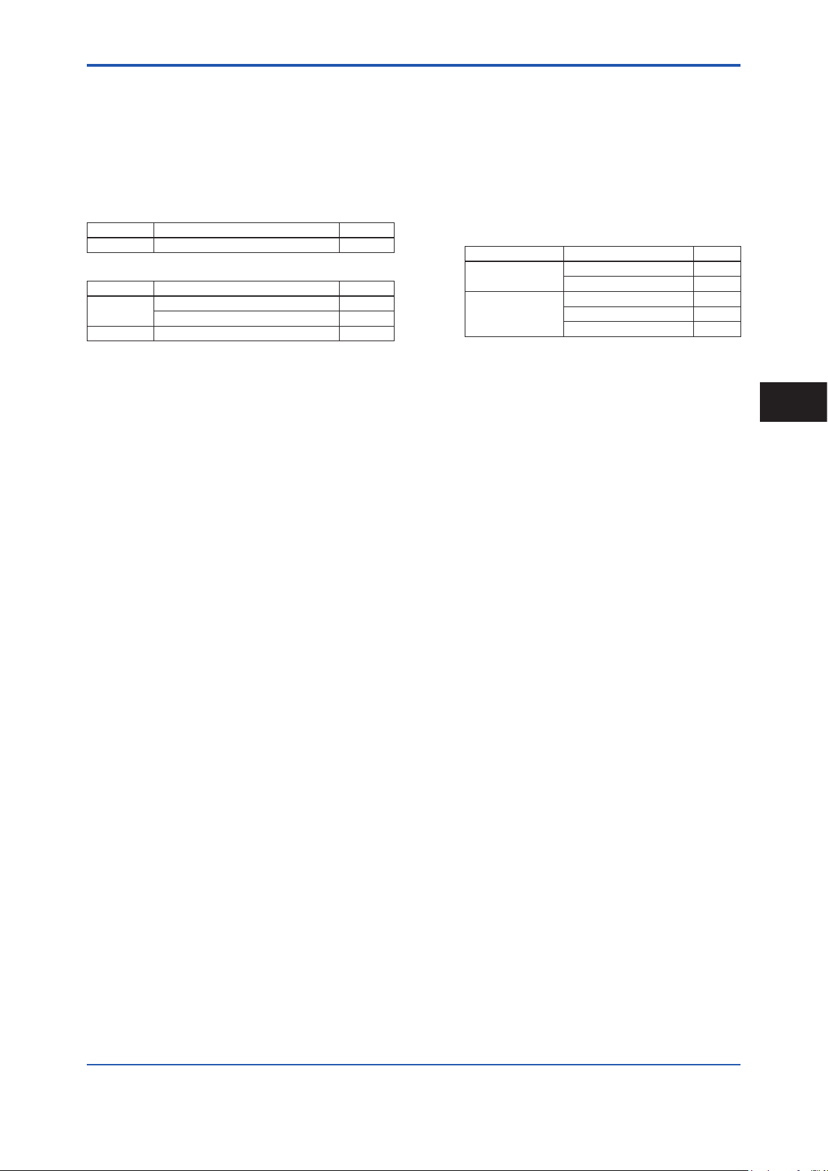
2. Receiving and Storage
When the instrument is delivered, visually check that no
damage has occurred during transportation. Also check
that all owmeters mounting hardware shown below is
included.
Integral Flowmeter
Model Part name Qty.
AXW###G Blanking Plug (*1) 0 to 2 pcs.
Remote Transmitter
Model Part name Qty.
AXW4A Mounting Bracket 1 set
Blanking Plug (*1) 0 to 2 pcs.
AXFA11G Mounting Bracket 1 set
*1: When the following code is specied for “Power Supply”
and “Converter, Communication, I/O”, the following
quantity of blind plug is attached.
Power Supply code
-1
-2
Communication and I/O code
-D, -E, or -M 1 pc.
Other than those above 0 pc.
-D or -E 2 pcs.
Other than those above 1 pc.
7
Qty
-P 0 pc.
2
Receiving and Storage
IM 01E25A01-01EN
<2. Receiving and Storage>
F0204.ai
F0201.ai
F0203.ai
F0202.ai
8
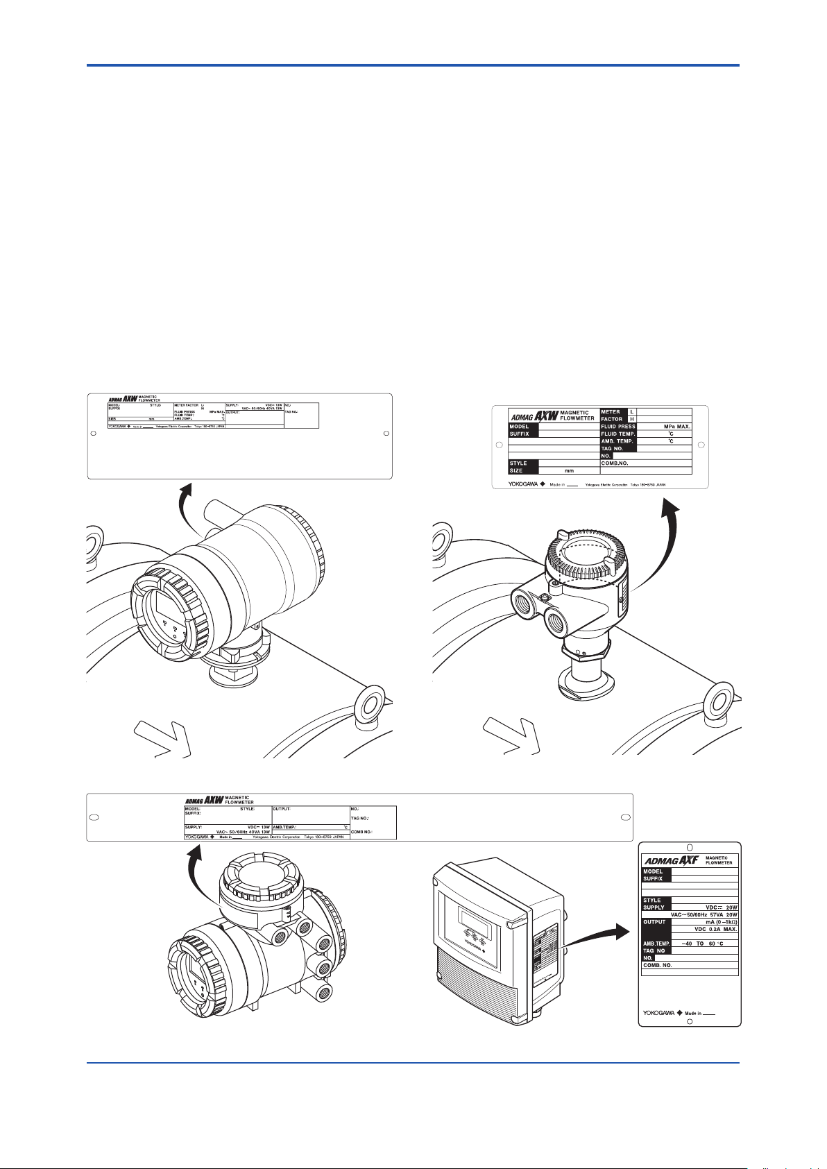
2.1 Model and Specications
Check
As shown in Figure 2.1 to Figure 2.4, the model, sufx
code, serial number, meter factor, uid specication, and
device information are found on the name plate located on
the outside of the housing. And, this instrument can check
their information from parameters. Read the user’s manual
of applicable communication type as listed in Table 1.1 for
checking device information from parameters.
When checking the matching of model and specication you
ordered, see the applicable general specications as listed in
Table 1.1.
Be sure you have the model code and serial number
available when contacting YOKOGAWA.
Note: Description on the nameplate
- Made in _______: Country of origin
- COMB No.: Serial number of the combined remote
sensor or remote transmitter
2.2 Storage Precautions
If the instrument is to be stored for a long period of time
after delivery, observe the following points.
The instrument should be stored in its original packing
condition in the storage location.
Select a storage location that fulls the following
conditions:
• A place where it will not be exposed to rain or water
• A place subject to minimal vibrations or shocks
•
Temperature and humidity levels should be as follows:
Temperature: -10 to 70°C
Humidity: 5 to 80% RH (no condensation)
The preferred ambient temperature and humidity
levels are 25°C and approximately 65% RH.
If the instrument is transferred to the installation site
and stored without being installed, its performance
may be impaired due to the inltration of rainwater
and so forth. Be sure to install and wire the instrument
as soon as possible after transferring it to the
installation location.
Figure 2.1 Name Plate (AXW Integral Flowmeter)
Figure 2.3 Name Plate (AXW4A Remote Transmitter)
Figure 2.2 Name Plate (AXW Remote Sensor)
Figure 2.4 Name Plate (AXFA11 Remote Transmitter)
IM 01E25A01-01EN
<3. Installation>
3. Installation
9
WARNING
Installation of the magnetic owmeter must be
performed by expert engineer or skilled personnel.
No operator shall be permitted to perform procedures
relating to installation.
Installation Location Precautions
Select the installation location with consideration to the
following items to ensure long-term stable operation of
the instrument.
Ambient Temperature:
Avoid installing the instrument in locations with constantly
uctuating temperatures. If the location is subject to
radiant heat from the plant, provide heat insulation or
improve ventilation.
Atmospheric Condition:
Avoid installing the instrument in a corrosive atmosphere.
In situations where this is unavoidable, consider ways to
improve ventilation and to prevent rainwater from entering
and being retained in the conduit pipes.
Vacuum:
In the case of PTFE lining, avoid the negative pressure
inside the measuring pipe.
Vibrations or Shocks:
Avoid installing the instrument in a place subject to
shocks or vibrations.
3.1 Piping Design Precautions
IMPORTANT
Design piping correctly, referring to the following to
prevent damage to sensors and to assure accurate
measuring.
NOTE
This section describes the remote sensor as an
example. The same attention must be paid to the
integral owmeter.
(1) Location
IMPORTANT
Install the owmeter in a location where it is not
exposed to direct sunlight. The minimum ambient
temperature is limited by the minimum uid temperature
of the sensor (the lining). For more information, read the
applicable general specication as listed inTable 1.1.
The owmeter may be used in an ambient humidity
where the relative humidity ranges from 0 to 100%.
However, avoid long-term continuous operation at
relative humidity 95% or higher.
3
Installation
(2) Noise Avoidance
IMPORTANT
The owmeter should be installed away from
electrical motors, transformers, and other power
sources in order to avoid interference with
measurement.
IM 01E25A01-01EN
F0301.ai
D: Sensor Size
2D or more
F0302.ai
(Incorrect)
Upstream side
(Correct)
Downstream side
Bypass valve
Block valve
F0303.ai
<3. Installation>
10
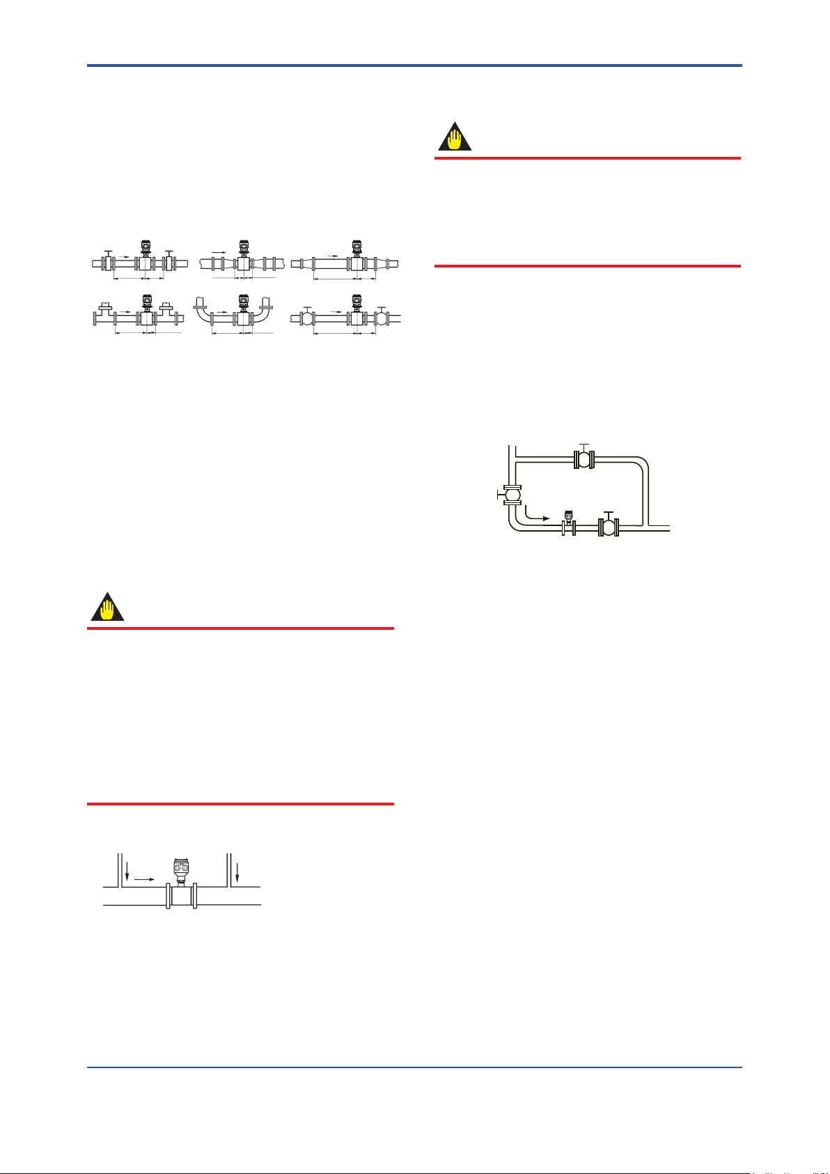
(3) Required Lengths of Straight Runs
Based on JIS B 7554 “Electromagnetic Flowmeters” and
our piping condition test data, we recommend the piping
conditions as shown in the following gures. This is not
always enough when the piping line incorporates multiple
conditions at the same time. When installing two or more
magnetic owmeters on a single pipe, provide a run of at
least 10D of the larger size between them.
Gate valve
fully open
5D or more2Dor more
Tee
0 is allowable.5D or more 0 is allowable.5D or more
Figure 3.1.1 Required Lengths of Straight Runs
*1: Do not install anything in the vicinity that may interfere
with the magnetic eld, induced signal voltages, or ow
velocity distributions of the owmeter.
*2: A straight run may not be required on the downstream
side of the owmeter. However, if a downstream valve
or other tting causes irregularity or deviation in ows,
provide a straight run of 2D to 3D on the downstream side.
*3: The valves shall be mounted on the downstream side so
that deviated ows do not occur in the sensor and to avoid
startup from an empty condition.
*4: In case the piping conditions are compounded, install
on the straight pipe section where the upstream part is
sufciently rectied.
Reducer
pipe
0 is allowable. 0 is allowable.
90-degree bend
Expander
pipe
10D or more
Various valves
10D or more
2D
or more
(5) Precautions for Use of Liquid Sealing
Compounds
IMPORTANT
Care must be taken in using liquid sealing compounds
on the piping, as it may have a negative inuence on
the ow indications by owing out and covering the
surfaces of an electrode or grounding ring. In particular,
care must be taken if a liquid sealing compound is used
in the case of vertical piping.
(6) Service Area
Select locations where there is adequate space to service
installing, wiring, overhauling, etc.
(7) Bypass Line
It is recommended to install a bypass line to facilitate
maintenance and zero adjustment.
Block valve
(4) Maintaining Stable Fluid Conductivity
IMPORTANT
Do not install the owmeter where uid conductivity
tends to become uneven. If chemicals are fed near
the upstream side of a magnetic owmeter, they may
affect the ow rate’s indications. To avoid this situation,
it is recommended that the chemical feed ports be
located on the downstream side of the owmeter. If
it is unavoidable that chemicals must be fed on the
upstream side, provide a sufcient length of straight
run (approximately 50D or more) to ensure the proper
mixture of uids.
Figure 3.1.2 Chemical Injection
Figure 3.1.3 Bypass Line
IM 01E25A01-01EN
<3. Installation>
F0304.ai
Abutment Abutment
F0305.ai
F0306.ai
(Incorrect)
F0307.ai
(Incorrect)
F0308.ai
Correct
the terminal
11
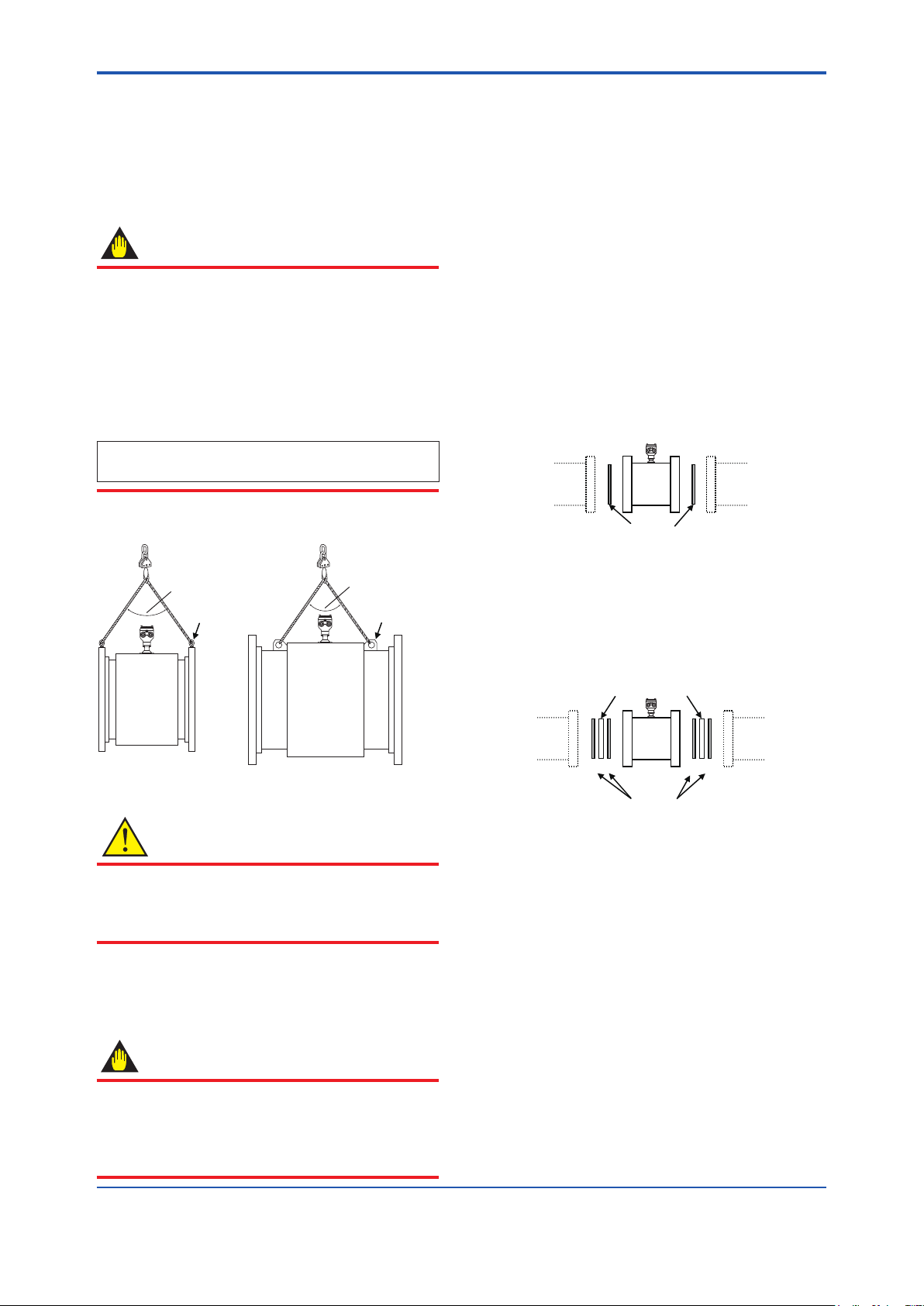
(8) Supporting the Flowmeter
CAUTION
Do not secure the owmeter separately to prevent the
vibrations, shocks, and expansion and contraction forces
of the piping from affecting it. Fix the pipes rst, then
support the owmeter with the pipes.
Magnetic flowmeter
To release the load from installing the owmeter to the
pipeline, set a expansive pipe in the downstream side.
Magnetic flowmeter
Abutment Abutment
For vertical mounting, make sure that the weight of piping
does not weigh on the owmeter.
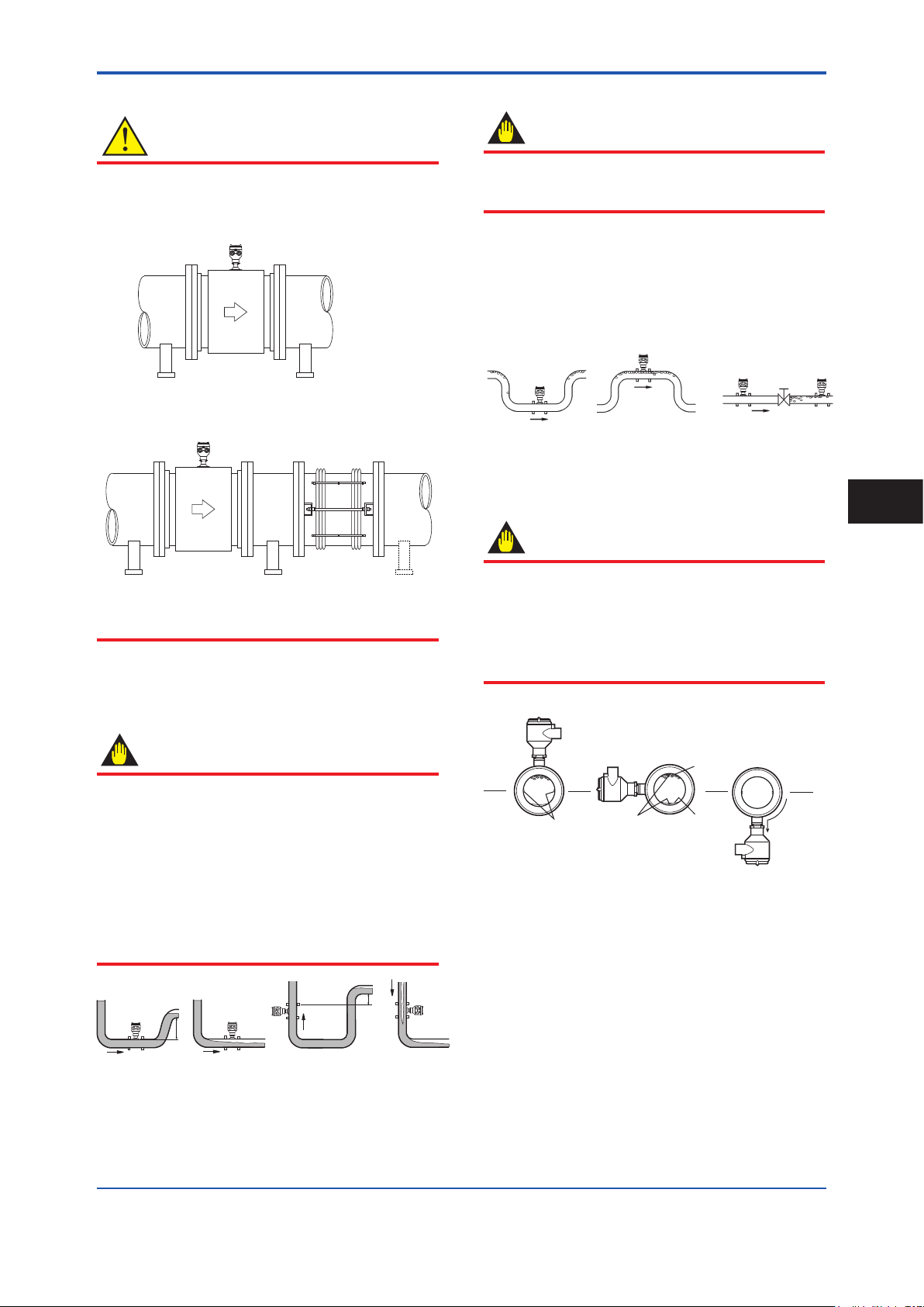
(9) Mounting Positions
Expansive pipe
Avoid air bubbles.
IMPORTANT
If air bubbles enter a measurement pipe, ow rate
indications may be affected and measurement errors
may be caused.
In cases where uids contain air bubbles, piping must
be designed to prevent them from accumulating in the
measurement pipe of a sensor.
If a valve exists near the owmeter, try to mount the
owmeter on the valve’s upstream side in order to
prevent a possible reduction of pressure inside the pipe,
thereby avoiding the possibility of air bubbles.
(Correct)
(Incorrect)
Figure 3.1.5 Avoiding Air Bubbles
(Correct)
Valve
Mounting orientation
IMPORTANT
If electrodes are perpendicular to the ground, air
bubbles near the top or precipitates at the bottom may
cause measurement errors. Ensure that the terminal
box of a remote sensor and transmitter of an integral
owmeter are mounted above the piping to prevent
water from entering them.
3
Installation
Pipes must be fully lled with liquids.
IMPORTANT
It is essential that pipes remain fully lled at all times,
otherwise ow rate indications may be affected and
measurement errors may be caused.
Piping shall be designed so as to maintain the interior of
the sensor lled with uids.
Vertical mounting is effective in such cases as
when uids tend to separate or solid matter may be
precipitated. When employing vertical mounting, direct
the uids from the bottom to the top to ensure that the
pipes remain fully lled.
(Correct)
Figure 3.1.4 Mounting Positions
(Incorrect)
h
h>0
(Correct)
h>0
h
Incorrect
Electrode
Figure 3.1.6 Mounting Orientation
Electrode
Air bubble
Precipitate
Incorrect
Water can
seep into
box.
IM 01E25A01-01EN
F0309.ai
<3. Installation>
12
3.2 Handling Precautions
WARNING
The magnetic owmeter is a heavy instrument.
Be careful that no damage is caused to personnel
through accidentally dropping it, or by exerting
excessive force on the magnetic owmeter. When
moving the magnetic owmeter, always use a trolley
and have at least two people carry it.
NOTE
This section describes the remote sensor as an
example. The same attention must be paid to the
integral owmeter.
3.2.1 General Precautions
(1) Precaution during Transportation
The magnetic owmeter is packed tightly. When
it is unpacked, pay attention to prevent damaging
the owmeter. To prevent accidents while it is being
transported to the installing location, transport it to the site
in its original packing.
(2) Avoid Shocks from Impact
CAUTION
Care should be taken not to drop the owmeter or
expose it to excessive shock. In particular, be careful
not to subject the ange surface to shock. This may
lead to lining damage which will result in inaccurate
readings.
(3) Flange Protection Covers
IMPORTANT
Keep the protective covering (i.e. the corrugated
cardboard or other cushioning material) in place over
the ange except when mounting the owmeter to the
pipe.
(4) Terminal Box Cover
IMPORTANT
As it is possible that the insulation will deteriorate, do
not open the terminal box cover until it is time to wire it.
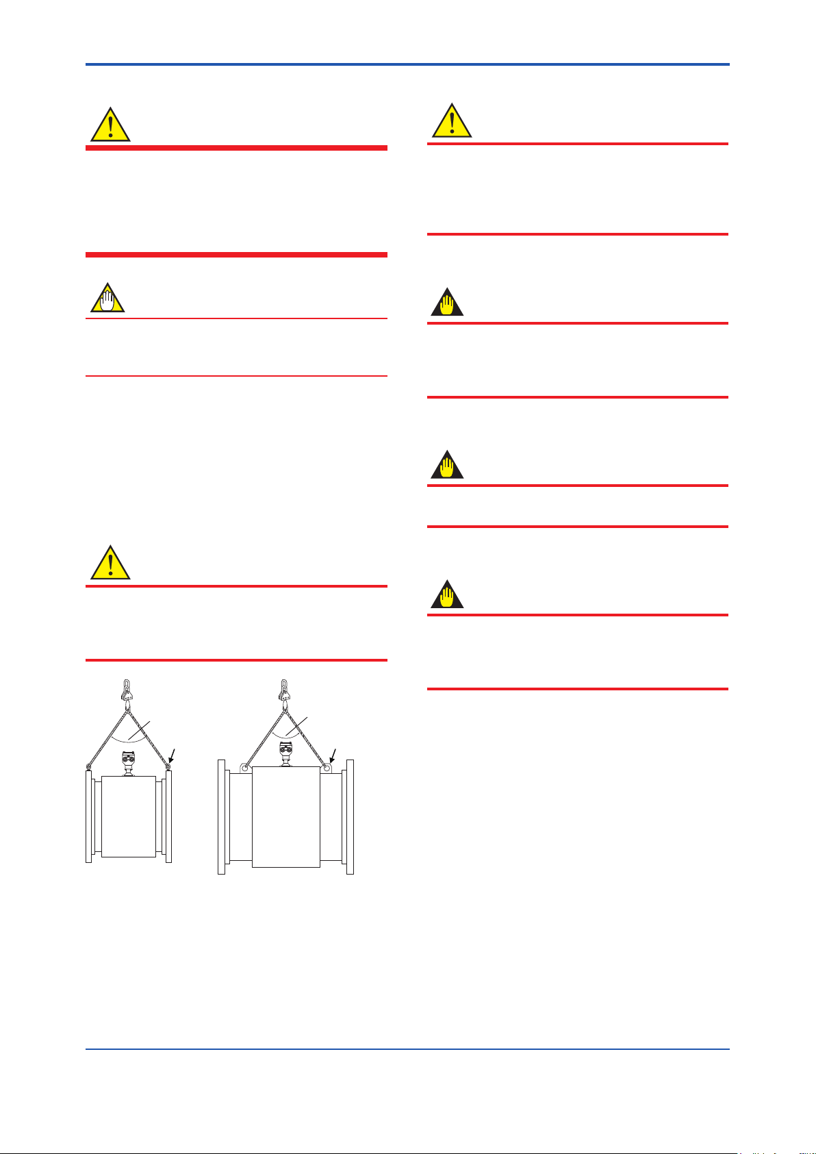
CAUTION
When lifting the magnetic owmeter, use the lifting rings
(eye bolts or eye plates) as in Figure 3.2.1.
Never lift it using a bar passed through the magnetic
owmeter as this damages the liner severely.
90 degrees or less
Eye bolt Eye plate
Figure 3.2.1 Lifting Flowmeter
90 degrees or less
(5) Long-term Non-use
IMPORTANT
It is not desirable to leave the owmeter unused
for a long term after installation. If this situation is
unavoidable, take care of the owmeter by observing
the following.
Conrmation of sealing conditions for the
owmeter
Conrm that the terminal box screw and electrical
connections are well sealed. Equip the conduit piping
with drain plugs or waterproof glands to prevent moisture
or water from penetrating into the owmeter through the
conduit.
Regular inspections
Inspect the sealing conditions as mentioned above, and
the inside of the terminal box at least once a year.
Also, due to rain, etc. when it is suspected that water may
have penetrated into the inside of the owmeter, perform
supplementary inspections.
IM 01E25A01-01EN
<3. Installation>
F0310.ai
13
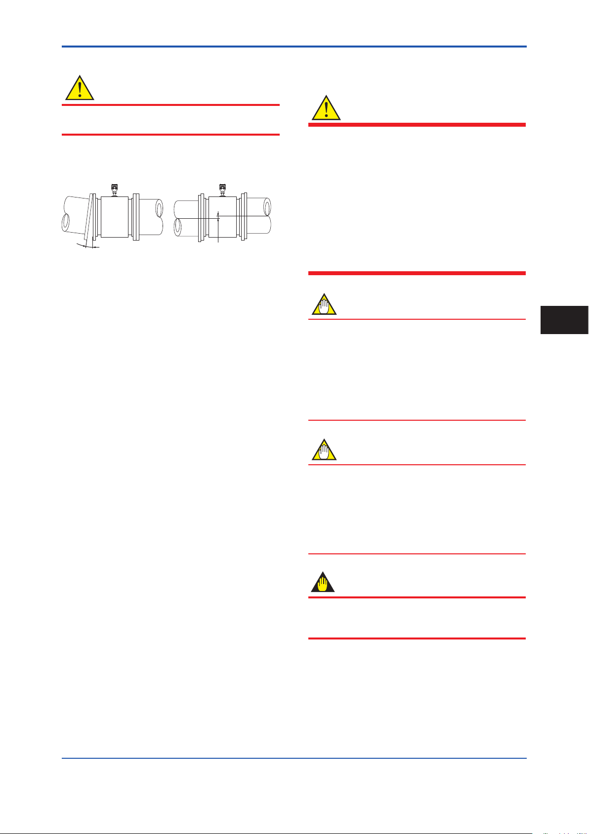
3.2.2 Flowmeter Piping
CAUTION
Misaligned or slanted piping can lead to leakage and
damage to the anges.
(1) Correct any misaligned or slanted piping, and any
gaps that may exist between mounting anges before
installing the owmeter (see Figure 3.2.2).
Slanted
Figure 3.2.2 Slanted and Misaligned Flowmeter Piping
(2) Inside a newly installed pipeline, there may be some
foreign substances such as residue from welding
or wood chips. Remove them by ushing the piping
before mounting the owmeter. This prevents the
lining from being damaged, as well as the occurrence
of erroneous measured signals resulting from foreign
substances passing through the sensor during
measurement.
Misaligned
3.3 Integral Flowmeter and Remote Sensor Installation
WARNING
• All gaskets used for piping of Magnetic Flowmeters
should be prepared by customers except in some
cases.
With the option of grounding ring, if the lining is
natural hard rubber or PTFE, gaskets must be
placed between each the grounding ring and the
sensor to avoid uid leakage. These gaskets are
to be supplied by customer. Do not forget those
gaskets also when ordering and attaching the
grounding rings later additionally.
• Use the gasket of the equivalent hardness for
gasket (customer pipe) and gasket (sensor).
NOTE
• The tightening torque of gaskets varies by the
type and external dimensions of the lining and the
gasket. The tightening torque values should be
decided by referring to Table 3.3.1.
• For uids capable of potentially permeating PTFE
linings (such as nitric acid, hydrouoric acid, or
sodium hydrate at high temperatures), do not use
the PTFE lining type.
3
Installation
NOTE
• The PTFE lining has a structure adhering PTFE to
the metal inner face of the sensor. When tightening
bolts and nuts to install to the piping, be careful not
to bring unequal stress or torque to the PTFE lining.
• For the PTFE lining, it is recommendedo be installed
with grounding rings, or to be installed with short
pipes at upstream and downstream sides.
IMPORTANT
Use bolts and nuts in compliance with the ange
ratings. When choosing the gaskets, be sure to choose
sheet gaskets designed to t for ange standard.
IM 01E25A01-01EN
A
A
<3. Installation>
14
(1) Mounting Direction
Mount the owmeter so that the ow direction of the uid
to be measured is in line with the direction of the arrow
mark on the owmeter. It may be especially difcult to
move large size sensors after bringing them into the pit.
Check directions before bringing.
IMPORTANT
If it is impossible to match the direction of the arrow
mark, the direction of the electrical connection can be
changed. Read Section 3.5.
In case the uid being measured ows against the
arrow direction, change the value from “Forward” to
“Reverse” at the parameter “Flow direct”. Read the
user’s manual of the applicable communication type
(for AXW/AXW4A) or the hardware/software edition
(for AXFA11) as listed in Table 1.1.
Display Menu Path (AXW/AXW4A):
Device setup ► Detailed setup ► AUX calculation ► Flow direct
(2) Lifting
90 degrees or less
Eye bolt
90 degrees or less
Eye plate
(4) Applying Gasket and optional Grounding
Rings
Gasket:
Necessary gaskets for piping connection are as
below depending on the choice of grounding rings.
Use sheet gaskets designed to t for the ange
ratings ad uid specications. The GF type-1
gaskets by JIS G 3443-2 should be used for the JIS
F12 ange models in sizes 1100 mm (44 in.) and
above. In this case, the gasket groove is required on
the customer pipe anges.
The thickness of gasket should be 2 mm (0.08 in.)
to 5 mm (0.2 in.) for sizes up to 1000 mm (40 in.),
and 5 mm (0.2 in.) or more for larger sizes. Use
soft rubber gasket, PTFE-sheathed non-asbestos
gasket, or its equivalent in hardness.
1. Standard (no grounding rings)
Customer
pipe
A A
Gaskets A supplied by customer
Figure 3.3.2 Installation without Grounding Rings
When using the GF type-1 gaskets, the gasket
groove is required as mentioned above.
Customer
pipe
F0312.ai
F0311.ai
Figure 3.3.1 Lifting
CAUTION
• When carrying the magnetic owmeter, use the
lifting rings (eye bolts or eye plates).
• To assure safety, keep lifting angle less than 90
degrees as shown in Figure 3.3.1
(3) Transportation and Positioning
Bring in the magnetic owmeter, place it and use a jack to
adjust its position.
IMPORTANT
Apply the jack to the anges of the magnetic
owmeter.
In addition, adjust any misalignment when the
magnetic owmeter is brought in, as the jack can
adjust vertical position, but not horizontal one.
2. With optional grounding rings (code GR1)
Optional grounding rings
Customer
pipe
B
Gaskets A and B supplied by customer
Figure 3.3.3 Installation with Grounding Rings GR1
B
Customer
pipe
F0313.ai
It is recommended to use the same gasket for A
and B. Both gaskets A and B are to be supplied
by customer.
When polyurethane or natural soft rubber lining,
the gaskets B are not necessary.
IM 01E25A01-01EN
<3. Installation>
15
3. With optional grounding rings (code GR2)
Optional grounding rings
with integrated gaskets B included
B
Customer
pipe
A A
Gaskets A supplied by customer
Figure 3.3.4 Installation with Grounding Rings GR2
B
Customer
pipe
F0314.ai
This is available for the models with process
connection JIS F12 (JIS 75M) in sizes 1100 mm
(44 in.) and above. Only gaskets A are to be
supplied by customer. Use soft rubber gasket,
PTFE-sheathed non-asbestos gasket, or its
equivalent in hardness.
The grounding rings are installed and locked
onto the magnetic owmeter with gaskets B
when shipped from factory.
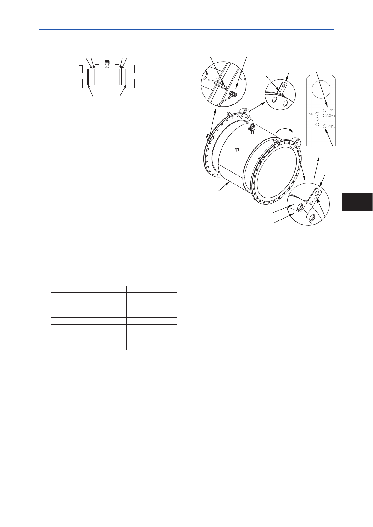
Mounting Procedure (no Grounding Rings):
Connect the magnetic owmeter’s ange and the
customer’s pipe which contact process uid by
some wire supplied by customer.
Mounting Procedure (with optional Grounding
Rings GR1 for sizes up to 1000 mm (40 in.)):
1. Handles of the grounding ring have some holes
which correspond to outer diameter of each
ange type. There are printings near each hole.
The printings show types of ange. See the
table below.
5. Install the magnetic owmeter into the
customer’s pipe with the gaskets A.
Centering Pin
Magnetic Flowmeter
Note : Gasket A and B are also placed concentrically with
Figure 3.3.5 Mounting Procedure with Grounding Rings
Screw & Nut : Connect the wire from the
grounding ring or the customer’s pipe
Centering Pin
Clockwise
Gasket B
Grounding Ring
the magnetic owmeter.
GR1 for sizes up to 1000 mm
(40 in.)
Handle
Printing of
Flange Type
F12
10K
Hole
Handle
Printed
Surface
F0315.ai
3
Installation
Printing
ASME -CA1
AWWA -CB1 AWWA C207 Class D
PN10 -CE1 EN1092-1 PN10
PN16 -CE2 EN1092-1 PN16
10K -CJ1 JIS B2220 10K
AS -CS1, -CS2, -CT1
F12 -CG1 JIS F12 (JIS 75M)
Process Connection Code
Flange Standard
ASME B16.5 Class 150,
ASME B16.47 Class 150
AS2129 table D, E
AS4087 PN16
2. Conrm the centering pin is xed to the hole
corresponding to ange or x the centering pin
to the correct hole.
3. Hang the grounding rings with their ange type
printings outer side of the magnetic owmeter.
Set the angle of both handles symmetrically to
be 45 degree from top. If there are any boltholes under the handles, turn the grounding
rings clockwise in order to locate handles
between bolt-holes. Center the grounding ring
to the center of the magnetic owmeter.
4. Connect the wire from the grounding ring to the
screw of the magnetic owmeter’s ange and
x the wire by the nut. This procedure (item
1 to 4) must be done for the both sides of the
magnetic owmeter.
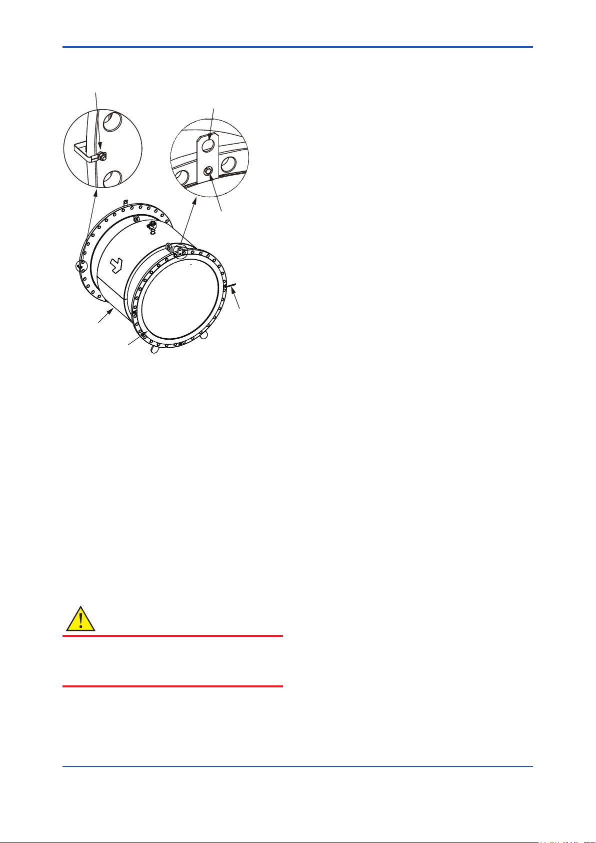
Mounting Procedure (with optional Grounding
Rings GR1 for sizes 1100mm (44 in.)) and above :
1. The grounding ring is temporarily xed onto
the magnetic owmeter by four bolts. Hang the
grounding ring up using a crane or a hoist so
that it would not fall down from the magnetic
owmeter while setting the gasket B.
2. Unfasten the bolts and remove the grounding
ring off from the magnetic owmeter.
3. Place the gasket B to the magnetic owmeter.
Cut out holes on the gasket B if necessary, so
that the bolts can go through. Fix the grounding
ring to the magnetic owmeter by the four bolts
again.
4. Connect the wire from the grounding ring to the
screw at the ange and x the wire by the nut.
This procedure (item 1 to 4) must be done for
the both sides of the magnetic owmeter.
IM 01E25A01-01EN
F0316.ai
<3. Installation>
5. Install the magnetic owmeter into the
customer’s pipe with the gaskets A.
Screw & Nut : Connect the wire from the
grounding ring or the customer’s pipe.
Magnetic Flowmeter
Hang the grounding
ring up with this point.
Unfasten the bolts and
remove the grounding rings.
Cut out some holes on the
gasket B when necessary.
Wire
16
Grounding Ring
Note : Gasket A and B should be placed concentrically with
the magnetic owmeter.
Figure 3.3.6 Mounting Procedure with Grounding Rings
GR1 for sizes 1100 mm (44 in.) and above
Mounting Procedure (with optional Grounding
Rings GR2):
The grounding rings are installed and locked onto
the magnetic owmeter with gaskets B when
shipped from factory. Install the magnetic owmeter
into the customer’s pipe with gaskets A supplied by
customer.
(5) Tightening Nuts
Pass the bolts from pipe line side, not magnetic owmeter
side, and tighten the nuts according to the torque values
for the metal piping in Table 3.3.1 or Table 3.3.2.
CAUTION
• Be sure to tighten the nuts according to the
prescribed toeque values. Tighten them diagonally
with the same torque values, step by up to the
prescribed torque value.
IM 01E25A01-01EN
 Loading...