

Page 1
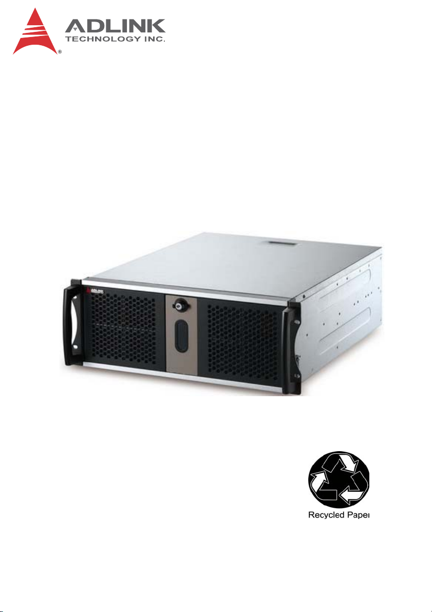
TRL-40
E-ATX Dual Intel® Xeon® E5 Series 4U Industrial
Server
User’s Manual
Manual Rev.: 2.01
Revision Date: Aug. 15, 2014
Part No: 50-1X009-1010
Advance Technologies; Automate the World.
Page 2
Revision History
Revision Release Date Description of Change(s)
2.00 2014/5/9 Initial release
2.01 2014/8/15
ii
Page 3

TRL-40
Preface
Copyright 2014 ADLINK Technology, Inc.
This document contains proprietary infor mation protected by copyright. All rights are reserved. No part of this manual may be reproduced by any mechanical, electronic, or other means in any form
without prior written permission of the manufacturer.
Disclaimer
The information in this document is subject to change without prior
notice in order to improve reliability, design, and function and does
not represent a commitment on the part of the manufa cturer.
In no event will the manufacturer be liable for direct, indirect, special, incidental, or consequential damages arising out of the use or
inability to use the product or documentation, even if advised of
the possibility of such damages.
Environmental Responsibility
ADLINK is committed to fulfill its social responsibility to global
environmental preservation through compliance with the European Union's Restriction of Hazardous Substances (RoHS) directive and Waste Electrical and Electronic Equipment (WEEE)
directive. Environmental protection is a top priority for ADLINK.
We have enforced measures to ensure that our products, manufacturing processes, components, and raw materials have as little
impact on the environment as possible. When products are at their
end of life, our customers are encouraged to dispose of them in
accordance with the product disposal and/or recovery programs
prescribed by their nation or company.
Trademarks
Product names mentioned herein are used for identification purposes only and may be trademarks and/or registered trademarks
of their respective companies.
Preface iii
Page 4
Conventions
Take note of the following conventions used throughout this
manual to make sure that users perform certain tasks and
instructions properly.
Additional information, aids, and tips that help users perform
tasks.
NOTE:
NOTE:
Information to prevent minor physical injury, component damage, data loss, and/or program corruption when trying to com-
CAUTION:
WARNING:
plete a task.
Information to prevent serious physical injury, component
damage, data loss, and/or program corruption when trying to
complete a specific task.
iv Preface
Page 5

TRL-40
Table of Contents
Preface.................................................................................... iii
List of Figures....................................................................... vii
List of Tables.......................................................................... ix
1 Introduction ........................................................................ 1
1.1 Overview.............................................................................. 1
1.2 Features............................................................................... 2
1.3 Specifications....................................................................... 3
1.4 Block Diagram ..................................................................... 7
1.5 Functional Description ......................................................... 7
1.6 Mechanical Drawings........................................................... 8
1.7 Rear I/O Connectors.......................................................... 11
1.8 Board Layout ..................................................................... 14
1.9 Onboard Connectors ......................................................... 16
1.10 Jumpers & Switches .......................................................... 18
2 Getting Started ................................................................. 23
2.1 Package Contents ............................................................. 23
2.2 Driver Installation............................................................... 23
Important Safety Instructions.............................................. 25
Getting Service...................................................................... 27
Table of Contents v
Page 6

This page intentionally left blank.
vi Table of Contents
Page 7

TRL-40
List of Figures
Figure 1-1: TRL-40 Block Diagram ....................................................7
Figure 1-2: TRL-40 Front View........................................................... 8
Figure 1-3: TRL-40 Rear View ........................................................... 9
Figure 1-4: TRL-40 Right Side View ..................................................9
Figure 1-5: TRL-40 Left Side View...................................................10
Figure 1-6: TRL-40 Top View...........................................................10
Figure 1-7: TRL-40 Underside View................................................. 11
Figure 1-8: TRL-40 Rear I/O Panel.................................................. 11
Figure 1-9: TRL-40 Board Layout ....................................................14
List of Figures vii
Page 8

This page intentionally left blank.
viii List of Figures
Page 9

TRL-40
List of Tables
Table 1-1: General Specifications.....................................................5
Table 1-2: Rear I/O Panel Legend.................................................. 12
Table 1-3: TRL-40 Board Layout Legend .......................................15
List of Tables ix
Page 10

This page intentionally left blank.
xList of Tables
Page 11

1 Introduction
1.1 Overview
The ADLINK TRL-40 is a 4U industrial server supporting the Intel
Xeon® Processor E5-2600 product family in a LGA2011 package,
delivering a scalable high performance platform for a wide array of
industrial applications. The TRL-40 supports 32/22nm dual CPUs
at up to 2.4 GHz with integrated memory controllers and Direct
Media Interface (DMI) connectivity to the Intel
channel DDR3 1600 MHz memory is supporte d up to a maximum
of 128 GB in eight DIMM slots.
These advanced features, coupled with integrated graphics, four
PCI Express x16 slots, one PCI Express x8 slot, one PCI Express
x4 slot, dual PCI Express-based Gigabit Ethernet, six SATA 6 Gb/
s ports and two SATA 3Gb/s ports make the TRL-40 ideal for
vision and automation control, medical, test & measurement, and
telecom applications requiring a high-perfo rmance, easy- to-dep loy
and reliable server.
All measurements shown are in mm.
®
C604 chipset. Dual
TRL-40
®
NOTE:
NOTE:
Introduction 1
Page 12

1.2 Features
X 430 W x 176 H x 567 D mm (16.9 x 6.9 x 22.3")(w/o handles)
X Supports dual Intel
LGA2011 package
X Dual channel DDR3 1600 MHz memory for each CPU, up to a
maximum of 128 GB in eight DIMM slots
X Four PCIe x16 slots, one PCIe x8 slot, one PCIe x4 slot
X One PCIe Mini Card slot support interface either mSATA or
PCIe Gen2/USB2.0 (selected by jumper)
X 6x SATA 6 Gb/s ports (one shared with mSATA, selected by
jumper)
X 2x SATA 3 Gb/s ports
X 8x USB 2.0 ports (2x onboard, 2x on front panel, 4x on rear
panel)
X Two UART interfaces (1 D-sub 9 on rear I/O supports RS-232/
422/485, 1 pin header supports RS-232)
X Dual Gigabit Ethernet
X Onboard pin header supports DB-Audio2 (optional accessory)
with Mic-in, Line-in and Line-out
X BMC AST2300 built-in 64MB VRAM @1920x1200 resolution
for VGA port
X IPMI support for
X AMI MegaRAC® Web GUI
X KVM/Media Redirection support
X Support for remote power-cycle, power-down, power-up and
reset by NIC1
X Serial over LAN (supported by rear I/O COM port)
X HW monitor: +12V,+5V,+3.3V, CPU voltage, CPU/Server tem-
perature, CPU/System fan speed
X Watchdog Timer:1-65535 seconds software programmable,
can generate system reset
X RoHS compliant
®
Xeon® Processor E5-2600 series in
Intelligent Platform Management Interface v.2.0
2Introduction
Page 13

1.3 Specifications
®
Xeon™ E5-2658, 2.1GHz, QPI 8GT/s, 20MB
Intel
Cache, 32nm, 95W TDP, LGA2011(8C)
®
Xeon™ E5-2648L, 1.8GHz, QPI 8GT/s, 20MB
Intel
Cache, 32nm, 70W TDP, LGA2011(8C)
®
Intel
Xeon™ E5-2620, 2.0GHz, QPI 7.2GT/s, 15MB
Cache, 32nm, 95W TDP, LGA2011(6C)
®
Intel
CPU
Xeon™ E5-2658 v2, 2.4GHz, QPI 8GT/s, 25MB
Cache, 22nm, 95W TDP, LGA2011(10C)
TRL-40
Product
IPC System
Model
TRL-40 series
Processor/System
®
Xeon™ E5-2648L v2, 1.9GHz, QPI 8GT/s, 25MB
Intel
Cache, 22nm, 70W TDP, LGA2011(10C)
Intel® Xeon™ E5-2640 v2, 2.0GHz, QPI 7.2GT/s,
20MB Cache, 22nm, 95W TDP, LGA2011(8C)
®
Intel
Xeon™ E5-2630 v2, 2.6GHz, QPI 7.2GT/s,
15MB Cache, 22nm, 80W TDP, LGA2011(6C)
Chipset Intel® C604
Dual-channel DDR3 1600MHz, 8x 240-pin DIMM
Memory
sockets, up to 128GB
ECC registered DIMMs or non-ECC unbuffered DIMM
support
BIOS AMI 64Mb SPI BIOS
Introduction 3
Page 14

IPMI
OS
ASPEED AST2300 BMC
IPMI v.2.0
®
AMI MegaRAC
web GUI.
KVM/Media redirection support
Support for remote power cycle, power down, power up
and reset by NIC1
Serial over LAN (support by rear side COM port)
HW monitor: +12V,+5V,+3.3V, CPU voltage, CPU/
motherboard temperature, CPU/system fan speed
Watchdog timer:1-65535 sec software programmable,
can generate system reset
®
Microsoft
Microsoft
Windows® Server 2008 R2 64-bit
®
Windows® 7 64-bit
RedHat™ Enterprise Linux 6
Power Supply
Single
600W PS/2 single power supply
100-240VAC, 9-4A, 47-63Hz
I/O
4x Serial ATA ports with 6 Gb/s data transfer rate from
Marvell 88SE9230
(SATA port from Marvell support RAID 0/1/10)
2x Serial ATA ports with 6 Gb/s data transfer rate from
Serial ATA
PCH
2x Serial ATA ports with 3 Gb/s data transfer rate from
PCH
(SATA port from PCH support RAID 0/1/5/10)
1x Mini PCIE full card slot support PCIe Gen2/USB or
m-SATA (signal share SAT A 6Gb/s port from PCH)
USB
Serial Port
8x USB 2.0 ports (4x rear side, 2x front side, 2x
onboard pin headers)
1x RS-232 (pin header), 1x RS-232/422/485(rear sides
connector)
4Introduction
Page 15

TRL-40
Slot 1: PCI Express x16 Gen3 from CPU1
Slot 2: PCI Express x16 Gen3 from CPU1
Expansion
Slots
Graphics BMC AST2300 built-in 64MB VRAM
VGA Dsub-15 connector, up to 1920x1200 resolution@60 Hz
Controller Dual Intel® GbE controller I210-AT (NIC0 and NIC1)
Interface PCI Express x1 bus
Slot 3: PCI Express x16 Gen3 from CPU2
Slot 4: PCI Express x8 Gen3 from CPU1
Slot 5: PCI Express x16 Gen3 from CPU2
Slot 6: PCI Express x4 Gen2 from PCH (physical PCIe
x8 slot)
Display
Ethernet
Wake On
LAN
Dimensions
Weight 21 kg net (46.3 lb)
Operating
Temperature
Storage
Temperature
Introduction 5
Yes
Mechanical/Environmental
430 W x 176 H x 567 D mm (16.9 x 6.9 x 22.3") (w/o
handles)
0˚C to 40˚C
-20˚C to 80˚C
Table 1-1: General Specifications
Page 16

NOTE:
NOTE:
Model naming convention is as follows:
TRL-40-AABBCCDEFFGHHH
Where:
AA:CPU
BB:RAM
CC:HDD
D:ODD
E: Power supply
FF:OS
G: Accessory
HHH:Reserved(000)
Example:TRL-40-22080210001000
22:-Intel Xeon E5-2658 v2, 2.4GHz, QPI 8GT/s, 25MB Cache,
22nm, 95W TDP, LGA2011(10C)x2
08: ECC/REG 8Gx8
02:3.5" 1TB x2
1:slim ODD
0:600W Single
00:WO/OS
1: W/Swapbay
000: N/A.
6Introduction
Page 17

TRL-40
1.4 Block Diagram
DDR3 1600 RDIMM
DDR3 1600 RDIMM
DDR3 1600 RDIMM
DDR3 1600 RDIMM
PCI-E x16
PCI-E x16
PCI-E mini card
(mSATA or PCIE)
SATA
SATA
SATA
PCI-E x8
MUX
Pin Header 2x5
P:2.54mm
RS232
USB x1
PCIE x1
SATA3.0 x1
MUX
SATA3.0 x1
SATA2.0 x2
USB x4
USB
Console
PCI-E x8
PCI-E x16
PCI-E x16
ALTERA
Port_80
Intel
Sandy Bridge EP
CPU 0
DMI x4
Patsburg- B
PCH
LPC
Port_80
Pin Header
Figure 1-1: TRL-40 Block Diagram
1.5 Functional Description
QPI
QPI
PCI-E x4
PCI-E x1
PCI-E x1
USB x 4
SPI
PCI-E x1
USB x 2
Intel
Sandy Bridge EP
CPU 1
IPMC
AST2300
SATA 3.0 x4
SATA
DDR3 1600 RDIMM
DDR3 1600 RDIMM
DDR3 1600 RDIMM
DDR3 1600 RDIMM
PCI-E x 2
PCI-E x16
PCI-E x16
Intel
I210AT
NC_SI
Intel
I210AT
BIOS
WOL support
WOL support
VGA
COM
RAID
PCI-E x16
Marvell
RJ45
RJ45
USB 2.0 x4
VGA
COM DSUB(RS232/422/485)
PCI-E x8
PCI-E x16
B
A
C
K
P
A
N
E
L
Processor Support
The TRL-40 is a dual processor design based on the Intel® Xeon
Processor E5-2600 family. One LGA-2011 socket connects to an
Intel C604 chipset through a 5 GHz Direct Media Interface (DM I).
The system clock generator is set by the processor delivering
100MHz host clock. Dual CPUs have their own onboard VRD
compliant to the VRM 12 specification. The VRD regulates+12V
from the DC-DC module to generate the required CPU core power
based on the CPU SVID. Each Xeon
®
E5-2600 processor has
dual-channel memory on 4 DIMMs supporting 800,1066, 1333,
and 1600 MT/s registered or un-buffered DIMM. Platform Environment Control Interface (PECI) for thermal monitoring and other
functions is supported.
Introduction 7
®
Page 18

Intel® C604 Chipset
The Intel® C600 Series chipset provides a connection point
between various I/O components and Direct Media Interfacebased processors. Eight lanes of PCI Express Gen2 ports are
supported.
Dual-Channel DDR3 Memory
The TRL-40 supports dual channel DDR3 1600 MT/s ECC registered or non-ECC unbuffered DIMMs up to 128GB total system
memory in eight DIMM slots.
Gigabit Ethernet
Dual Intel® GbE I210-AT Controllers are connected from the Intel
C604 chipset.
Serial ATA
The Marvell 88SE9230 is a four-port SATA RAID I/O processor
that provides a two-lane PCI Express 2.0 in-terface and SATA
controller functions. The 88SE9230 supplies four 6Gbps SATA
ports. Intel
3 Gb/s ports.
®
C604 chipset supports 2x SATA 6 Gb/s and 2x SATA
®
1.6 Mechanical Drawings
481
175
Figure 1-2: TRL-40 Front View
8Introduction
Page 19

101.6
TRL-40
10.3
7.1
465
Figure 1-3: TRL-40 Rear View
23
92.192.192.1101
52.7
23
Figure 1-4: TRL-40 Right Side View
50
88
10#-32
16.4
Introduction 9
Page 20

Figure 1-5: TRL-40 Left Side View
Figure 1-6: TRL-40 Top View
10 Introduction
Page 21

TRL-40
Figure 1-7: TRL-40 Underside View
The TRL-40 must be protected from static discharge and physical shock. Never remove any of the socketed parts except at a
WARNING:
static-free workstation. Use the anti-static bag shipped with the
product to handle the board. Wear a grounded wrist strap when
installing and/or servicing.
1.7 Rear I/O Connectors
ABCDE
Figure 1-8: TRL-40 Rear I/O Panel
Introduction 11
Page 22

A VGA
B RS-232/422/485
C 4x USB 2.0
D NIC0
E NIC1
Table 1-2: Rear I/O Panel Legend
Serial Port Connector (COM1)
Pin # RS-232 RS422 RS485
1 DCD, Data Carrier Detect TXD- Data2 RXD, Receive Data TXD+ Data+
3 TXD, Transmit Data RXD+ -4 DTR, Data Terminal Ready RXD- -5 GND, ground GND GND
6 DSR, Data Set Ready -- -7 RTS, Request to Send -- -8 CTS, Clear to Send -- -9 RI, Ring Indicator -- --
VGA Connector.
Signal Name Pin # Pin # Signal Name
Red 1 2 Green
Blue 3 4 VCC pull-up
GND 5 6 GND
GND 7 8 GND
VCC 9 10 GND
VCC pull-up 11 12 DDC2B DATA
HSYNC 13 14 VSYNC
DDC2B CLK 15
12 Introduction
Page 23

TRL-40
LAN Port (NIC0/1, RJ-45)
Refer to the tables below for the LAN port pin and LED definitions.
Pin #
1 TX+ BI_DA+
2 TX- BI_DA3 RX+ BI_DB+
4 -- BI_DC+
5-- BI_DC6 RX- BI_DB7 -- BI_DD+
8-- BI_DD-
LAN Status LED1 (left) LED2(right)
Network link is not established
WARNING:
10BASE-T/
100BASE-TX
or system power off
10 Mbps OFF Blinking
100 Mbps Green Blinking
1000 Mbps Orange Blinking
NIC1 supports NCSI for IPMI v2.0
1000BASE-T
LED1
OFF OFF
LED2
18
USB Connectors
Pin # Signal Name
1Vcc
2 USB3 USB+
4GND
Introduction 13
Page 24

1.8 Board Layout
Figure 1-9: TRL-40 Board Layout
14 Introduction
Page 25

ATXPWR1 ATX Power Connector (24-pin)
CLR-RTC1 Clear RTC Jumper
CPU_FAN1/2 CPU Fan Connectors
H_AUDIO1 Audio Daughter Board Header
H_COM2 Serial Port Connector
H_FRONT1 System Panel Pin Header
H_USB1~2 USB 2.0 Pin Headers
JP1 Clear CMOS Jumper
JP2 Marvell SATA RAID Test Mode Jumper
JP3 BMC Console Port
JP4/JP8 PCIe Mini-Card Function Selection Ju mp er
JP5 SATA1 Function Selection Jumper
JP6/JP7 COM1 Mode Selection Jumper
P12VPWR1 EPS 12V Power Connector (8-pin)
P12VPWR2 AT X12V Power Connector (4-pin)
PCIE_SLOT1~6 PCI Express Slots
RAID_SATA1~4 SATA Connector (RAID support)
SATA1~4 SATA Connector
SYS _FAN1~4 System Fan Connector
Table 1-3: TRL-40 Board Layo ut Legend
TRL-40
Introduction 15
Page 26

1.9 Onboard Connectors
Serial Port Connector - RS-232 (COM2)
Pin # Signal Fun ction
1 DCD Data Carrier Detect
2 DSR Data Set Ready
3 RXD Receive Da ta
4 RTS Request to Send
5 TXD Transmit Data
6 CTS Clear to Send
7 DTR Data Terminal Ready
8 RI Ring Indicate
9 GND Ground
10 NC Key
CPU/System Fan Connectors (CPU_FAN#/SYS_FAN#)
Pin # Signal
1 Fan Speed Control
2 Fan Tachometer
3 Fan power (+12V)
4GND
1
12
910
4
16 Introduction
Page 27

HD Audio Daughter Board Connector (H_AUDIO1)
This connector is designed for use with the ADLINK DB-Audio2
daughter board.
Pin # Signal Function
1 GND Ground
2 AUD_BCLK Audio Clock
3 GND Ground
12
910
4 ICH_AUD_SDIN1 Audio Data Input
5 P5V + 5V
6 ICH_AUD_SDOUT Audio Data Output
7 P5V_AUD + 5V
8 P3V3_DVDD 3.3V
9 AUD_SYNC Audio Synchronous
10 AUD_RSTJ Audio Reset
System Panel Pin Header (H_FRONT1)
PIN Signal Name PIN Signal Name
1 HC_SPKR_N 11 GND
2 NC 12 SYS_RSTBTN-L
3NC13 NC
45V14GND
5 NC 15 CN_PWRBTN-L
6 GND 16 NC
7 HC_LEYLOCK-L 17 NC
8 HC_PLED-L 18 LED_SATA_ACT-L
9 NC 19 3V_HLED
10 5V_PLED 20 NC
1
10 20
TRL-40
11
Introduction 17
Page 28

SATA Connectors
Pin # Signal
1GND
2TXP
3TXN
4GND
5RXN
6RXP
7GND
USB 2.0 Pin Headers (H_USB1~2)
Pin # Signal Pin # Signal
1+5V2+5V
3 USB0- 4 USB15 USB0+ 6 USB1+
7 GND 8 GND
9 Key 10 NC
1.10 Jumpers & Switches
1
7
Clear RTC (CLR_RTC1)
Clear BIOS settings and data/time.
CMOS Status Connection JP1
Normal 1 – 2
Clear RTC 2 – 3
18 Introduction
Page 29

Clear CMOS (JP1)
Clear the BIOS settings.
CMOS Status Connection JP1
Normal 1 – 2
Clear CMOS 2 – 3
Marvell SATA RAID Test Mode (JP2)
For debug use.
Status Connection JP2
Normal 1 – 2
Enable 2 – 3
TRL-40
Introduction 19
Page 30

BMC Console Port (JP3)
Pin # Signal
1 VCC 3.3V
2RX
3TX
4GND
PCIe Mini-Card Function Selection (JP4/JP8)
Status Connection JP1
mSATA 1 – 2
PCIe (default) 2 – 3
SATA1 Function Selection (JP5)
Disable to use PCIe Mini-Card in mSATA mode.
Status Connection JP2
SATA (default) 1 – 2
Disabled 2 – 3
COM1 Mode Selection (JP6/JP7)
Status JP6 JP7
RS-232 Short 2-3 Short 1-2
RS-422 Short 2-3 Short 2-3
RS-485 Short 1-2 Short 2-3
20 Introduction
Page 31

TRL-40
Introduction 21
Page 32

This page intentionally left blank.
22 Introduction
Page 33

2 Getting Started
2.1 Package Contents
Before unpacking, check the shipping carton for any damage. If
the shipping carton and/or contents are damaged, inform your
dealer immediately. Retain the shipping carton and packing materials for inspection. Obtain authorization from the dealer before
returning any product to ADLINK.
X TRL-40 system server
X Driver CD
X Quick Start Guide
2.2 Driver Installation
The following provides information on how to install the TRL-40
device drivers in Windows 7 64-bit. The device drivers are located
in the following ADLINK All-in-One CD directories:
Display X:\IMB-S90\Graphics
Chipset X:\IMB-S90\Intel INF
Ethernet X:\IMB-S90\LAN
Rapid
Storage
RAID X:\IMB-S90\Marvell
X:\IMB-S90\Intel RST
TRL-40
To install the required TRL-40 drivers:
1. Install the Windows operating system before installing
any driver. Most standard I/O device drivers are installed
during Windows installation.
2. Install the Display driver by opening device manager.
Navigate to the INF located in X:\IMB-S90\Graph-
ics\v098_whql
\Windows_WDDM\Win7_S08R2_x64. Follow the
instructions given and reboot when ins tru ct ed .
3. Install the Chipset driver by running the program
Setup.exe in X:\IMB-S90\Intel INF\infinst_autol for
Getting Started 23
Page 34

XXX (where XXX is Sandy Bridge or Ivy Bridge). Follow
the instructions given and reboot when instructed.
4. Install the Ethernet driver by running the program
Autorun.exe from X:\IMBS90\LAN\513189_Release_17_4_OEM_Gene_284334
_split. Follow the instructions given and reboot if
required.
5. Install the Marvel RAID driver by opening device manager. Navigate to the driver located in X:\IMB-S90\Mar-
vell\PSP2.3.0.1046\windows\Driver\1.2.0.1032WHQL\storport\amd64. Follow the instructions given
and reboot if required.
24 Getting Started
Page 35

TRL-40
Important Safety Instructions
For user safety, please read and follow all instructions,
WARNINGS, CAUTIONS, and NOTES marked in this manual
and on the associated equipment before handling/operating the
equipment.
X Read these safety instructions carefully
X Keep this user’s manual for future reference
X Read the specifications section of this manual for detailed
information on the operating environment of this equipment
X When installing/mounting or uninstalling/removing
equipment, turn off power and unplug any power cords/
cables
X To avoid electrical shock and/or damage to equipment
Z Keep equipment away from water or liquid sources
Z Keep equipment away from high heat or high humidity
Z Keep equipment properly ventilated (do not block or
cover ventilation openings)
Z Make sure to use recommended voltage and powe r
source settings
Z Always install and operate equipment near an easily
accessible electrical socket-outlet
Z Secure the power cord (do not place any obje ct on /ove r
the power cord)
Z Only install/attach and operate equipment on stable
surfaces and/or recommended mountings
Z If the equipment will not be used for long periods of time,
turn off and unplug the equipment from its power source
Important Safety Instructions 25
Page 36

X Never attempt to fix the equipment. Equipmen t sho u ld on ly
be serviced by qualified personnel.
X Operation at altitudes exceeding 2000 m is not recom-
mended
X It is recommended that equipment be installed only in a
server room or computer room where:
Z Access is restricted to qualified service personnel or
users familiar with restrictions applied to the location,
reasons therefor, and any precautions required, and
Z Access is only afforded by the use of a tool or lock and
key, or other means of security, and is controlled by the
authority responsible for the location.
A Lithium-type battery may be provided for uninterrupted, backup
or emergency power.
Risk of explosion if battery is replaced with one of an incorrect
type. Dispose of used batteries appropriately.
WARNING:
Risque d'explosion si la batterie est remplacée par un type
incorrect; s'il vous plaît jeter les piles usagées de façon appropriée.
X Equipment must be serviced by authorized technicians
when:
Z The power cord or plug is damaged;
Z Liquid has penetrated the equipment;
Z It has been exposed to high humidity/moisture;
Z It is not functioning or does not function according to the
user’s manual;
Z It has been dropped and/or damaged; and/or,
Z It shows obvious signs of breakage.
26 Important Safety Instructions
Page 37

Getting Service
Contact us should you require any service or assistance.
ADLINK Technology, Inc.
Address: 9F, No.166 Jian Yi Road, Zhonghe District
New Taipei City 235, Taiwan
ᄅקؑխࡉ৬ԫሁ 166 ᇆ 9 ᑔ
Tel: +886-2-8226-5877
Fax: +886-2-8226-5717
Email: service@adlinktech.com
Ampro ADLINK Technology, Inc.
Address: 5215 Hellyer Avenue, #110
San Jose, CA 95138, USA
Tel: +1-408-360-0200
Toll Free: +1-800-966-5200 (USA only)
Fax: +1-408-360-0222
Email: info@adlinktech.com
ADLINK Technology (China) Co., Ltd.
Address: Ϟ⍋Ꮦ⌺ϰᮄᓴ∳催⾥ᡔು㢇䏃 300 ো(201203)
300 Fang Chun Rd., Zhangjiang Hi-Tech Park
Pudong New Area, Shanghai, 201203 China
Tel: +86-21-5132-8988
Fax: +86-21-5132-3588
Email: market@adlinktech.com
TRL-40
ADLINK Technology Beijing
Address: ࣫ҀᏖ⍋⎔Ϟഄϰ䏃 1 োⲜ߯ࡼ E ᑻ 801 ᅸ(100085)
Beijing, 100085 China
Tel: +86-10-5885-8666
Fax: +86-10-5885-8626
Email: market@adlinktech.com
ADLINK Technology Shenzhen
Address: ⏅ഇᏖቅ⾥ᡔು催ᮄϗ䘧᭄ᄫᡔᴃು
Tel: +86-755-2643-4858
Fax: +86-755-2664-6353
Email: market@adlinktech.com
LiPPERT ADLINK Technology GmbH
Address: Hans-Thoma-Strasse 11, D-68163
Mannheim, Germany
Tel: +49-621-43214-0
Fax: +49-621 43214-30
Email: emea@adlinktech.com
Rm. 801, Power Creative E, No. 1 Shang Di East Rd.
A1 2 ὐ C (518057)
2F, C Block, Bldg. A1, Cyber-Tech Zone, Gao Xin Ave. Sec. 7
High-Tech Industrial Park S., Shenzhen, 518054 China
Getting Service 27
Page 38

ADLINK Technology, Inc. (French Liaison Office)
Address: 6 allée de Londres, Immeuble Ceylan
91940 Les Ulis, France
Tel: +33 (0) 1 60 12 35 66
Fax: +33 (0) 1 60 12 35 66
Email: france@adlinktech.com
ADLINK Technology Japan Corporation
Address: ͱ101-0045 ᵅҀ䛑ҷ⬄⼲⬄䤯ފ⬎ 3-7-4
Tel: +81-3-4455-3722
Fax: +81-3-5209-6013
Email: japan@adlinktech.com
ADLINK Technology, Inc. (Korean Liaison Office)
Address: 137-881 昢殾柢 昢爎割 昢爎堆嵢 326, 802 (昢爎壟, 微汾瘶捒娯)
Tel: +82-2-2057-0565
Fax: +82-2-2057-0563
Email: korea@adlinktech.com
ADLINK Technology Singapore Pte. Ltd.
Address: 84 Genting Lane #07-02A, Cityneon Design Centre
Tel: +65-6844-2261
Fax: +65-6844-2263
Email: singapore@adlinktech.com
ADLINK Technology Singapore Pte. Ltd. (Indian Liaison Office)
Address: #50-56, First Floor, Spearhead Towers
Malleswaram, Bangalore - 560 055, India
Tel: +91-80-65605817, +91-80-42246107
Fax: +91-80-23464606
Email: india@adlinktech.com
⼲⬄ 374 ɛɳ 4F
KANDA374 Bldg. 4F, 3-7-4 Kanda Kajicho,
Chiyoda-ku, Tokyo 101-0045, Japan
802, Mointer B/D, 326 Seocho-daero, Seocho-Gu,
Seoul 137-881, Korea
Singapore 349584
Margosa Main Road (between 16th/17th Cross)
ADLINK Technology, Inc. (Israeli Liaison Office)
Address: 27 Maskit St., Corex Building
PO Box 12777
Herzliya 4673300, Israel
Tel: +972-77-208-0230
Fax: +972-77-208-0230
Email: israel@adlinktech.com
ADLINK Technology, Inc. (UK Liaison Office)
Tel: +44 774 010 59 65
Email: UK@adlinktech.com
28 Getting Service
 Loading...