

Page 1
TPZ-1300
Intel® Atom™ D2550/N2600 Fanless
Embedded Computer with Integrated I/O
Manual Rev.: 2.00
Revision Date: Dec. 26, 2012
Part No: 50-1Z142-3000
Advance Technologies; Automate the World.
Page 2

Revision History
Revision Release Date Description of Change(s)
2.00 Dec. 26, 2012 Initital Release
ii
Page 3

TPZ-1300
Preface
Copyright 2012 ADLINK Technology, Inc.
This document contains proprietary information protected by copyright. All rights are reserved. No part of this manual may be reproduced by any mechanical, electronic, or other means in any form
without prior written permission of the manufacturer.
Disclaimer
The information in this document is subject to change without prior
notice in order to improve reliability, design, and function and does
not represent a commitment on the part of the manufacturer.
In no event will the manufacturer be liable for direct, indirect, special, incidental, or consequential damages arising out of the use or
inability to use the product or documentation, even if advised of
the possibility of such damages.
Environmental Responsibility
ADLINK is committed to fulfill its social responsibility to global
environmental preservation through compliance with the European Union's Restriction of Hazardous Substances (RoHS) directive and Waste Electrical and Electronic Equipment (WEEE)
directive. Environmental protection is a top priority for ADLINK.
We have enforced measures to ensure that our products, manufacturing processes, components, and raw materials have as little
impact on the environment as possible. When products are at their
end of life, our customers are encouraged to dispose of them in
accordance with the product disposal and/or recovery programs
prescribed by their nation or company.
Trademarks
Product names mentioned herein are used for identification purposes only and may be trademarks and/or registered trademarks
of their respective companies.
Conventions
Take note of the following conventions used throughout this
manual to make sure that users perform certain tasks and
instructions properly.
Preface iii
Page 4
Additional information, aids, and tips that help users perform
tasks.
NOTE:
NOTE:
Information to prevent minor physical injury, component dam-
age, data loss, and/or program corruption when trying to com-
CAUTION:
plete a task.
Information to prevent serious physical injury, component
damage, data loss, and/or program corruption when trying to
WARNING:
complete a specific task.
Symbology
The following symbols may be used throughout this manual.
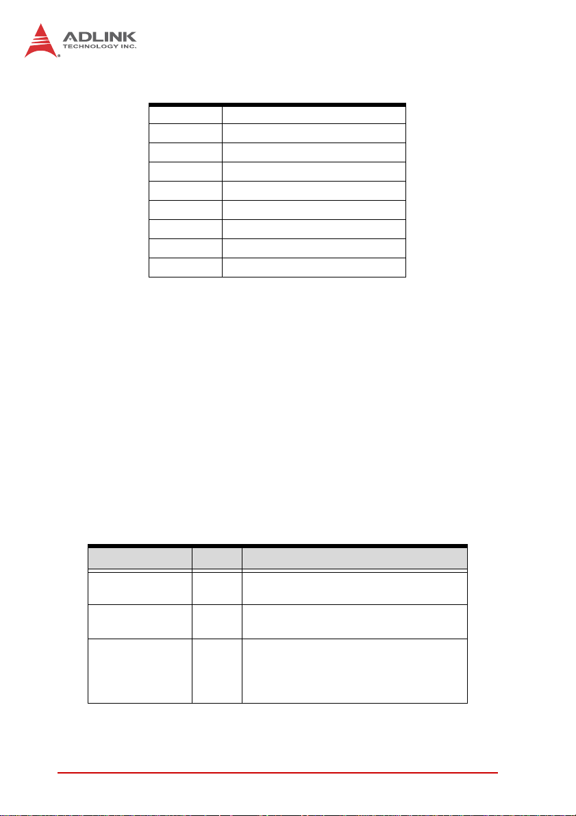
Symbol Meaning
Universal Power Standby Symbol (IEC 5009, according to
the International Electrotechnical Commission 60417
standard)
Please consult operating instructions for information
regarding proper use of the device (ISO 7000-1641)
Earth Ground Terminal, directly connected to a circuit or
screening part
iv Preface
Page 5

TPZ-1300
Table of Contents
Revision History...................................................................... ii
Preface.................................................................................... iii
List of Figures........................................................................ ix
List of Tables.......................................................................... xi
1 Introduction ........................................................................ 1
1.1 Overview.............................................................................. 1
1.2 Features............................................................................... 2
1.3 Specifications....................................................................... 3
Electronic Considerations and Requirements ................. 5
1.4 Mechanical Drawings........................................................... 7
1.5 Front Panel I/O Connectors ................................................. 9
1.5.1 Power Button ............................................................ 10
1.5.2 LED indicators .......................................................... 10
1.5.3 Reset Button............................................................. 11
1.5.4 VGA Connector ........................................................ 11
1.5.5 DVI-D Connector ...................................................... 11
1.5.6 USB 2.0 Connectors................................................. 11
1.5.7 Compact-Flash Port.................................................. 11
1.5.8 Gigabit Ethernet (Intel 82574L) ................................ 12
1.5.9 Active/Link & Speed LEDs........................................ 12
1.5.10 MIC & Speaker Jacks ............................................... 13
1.6 Rear Panel I/O Connectors................................................ 14
1.6.1 DC Power Supply Connector.................................... 14
1.6.2 COM Ports................................................................ 15
1.6.3 Digital I/O Connector ................................................ 16
1.6.4 Antenna Connector................................................... 18
1.7 Internal I/O Connectors...................................................... 19
Table of Contents v
Page 6

1.7.1 SATA Slot ................................................................. 20
1.7.2 LVDS Interface Connector (optional)........................ 20
1.7.3 Clear CMOS Jumper ................................................ 21
1.7.4 LVDS Backlight Power Connector (optional) ............ 22
1.7.5 LVDS Voltage Selected Jumper (optional) ............... 23
1.7.6 Mini PCI Express Slot & USIM Socket...................... 23
1.7.7 Extra +3.3 V/ +5 V Voltage Internal Connectors....... 23
1.7.8 Reset/Power Button Extension Internal Connector .. 24
2 Getting Started.................................................................. 27
2.1 Unpacking Checklist .......................................................... 27
2.2 Installing a Hard Disk Drive ............................................... 28
2.3 Installing a CF Card ........................................................... 33
2.4 Connecting DI/O Device .................................................... 34
2.5 Connecting DC power........................................................ 35
2.6 Wall-mounting the TPZ-1300 ............................................. 36
2.7 Cooling Configuration ........................................................ 39
3 Driver Installation.............................................................. 41
3.1 Installing the chipset driver ................................................ 41
3.2 Installing the graphics driver .............................................. 42
3.3 Installing the Ethernet driver .............................................. 42
3.4 Installing the audio driver ................................................... 43
3.5 Installing the WDT and DI/O drivers .................................. 43
A Appendix: Watchdog Timer (WDT) &
DI/O Function Libraries..........................................................45
A.1 WDT with API/Windows ..................................................... 45
InitWDT ......................................................................... 45
SetWDT ........................................................................ 46
A.2 DI/O with API/Windows ...................................................... 48
GPIO_Init ...................................................................... 48
GPI_Read() ................................................................... 48
vi Table of Contents
Page 7

TPZ-1300
GPO_Write() ................................................................. 49
GPO_Read() ................................................................. 49
B Appendix: BIOS Setup......................................................51
B.1 Main ................................................................................... 52
B.1.1 BIOS Information ...................................................... 52
B.1.2 PC Health Status ...................................................... 52
B.1.3 System Time/System Date ....................................... 52
B.2 Advanced........................................................................... 53
B.2.1 CPU Configuration.................................................... 54
Hyper-Threading ........................................................... 55
Execute Disable Bit ....................................................... 55
Limit CPUID Maximum ................................................. 55
B.2.2 Onboard Device Configuration ................................. 56
Serial Port 1~4 Configuration ....................................... 56
Launch Intel 82574 LAN PXE OpROM ......................... 56
SATA Controller(s) ........................................................ 56
SATA Mode Selection ................................................... 56
Legacy USB Support .................................................... 57
B.2.3 Advanced Power Management ................................ 57
Restore AC Power Loss ............................................... 57
System Watchdog ......................................................... 58
Wake System With Fixed Time ..................................... 58
Wake On Ring .............................................................. 58
B.2.4 SATA Configuration.................................................. 58
B.2.5 Serial Port Console Redirection ............................... 59
Console Redirection ..................................................... 60
Out-of-Band Mgmt Port ................................................. 60
Terminal Type ............................................................... 60
B.3 Chipset............................................................................... 60
Primary IGFX Boot Display ........................................... 60
Active LFP .................................................................... 61
Table of Contents vii
Page 8

B.4 Boot ................................................................................... 61
Setup Prompt Timeout .................................................. 61
Bootup Num-Lock State ................................................ 61
Quiet Boot ..................................................................... 61
Fast Boot ...................................................................... 62
Boot Option Priorities .................................................... 62
Hard Drive BBS Priorities ............................................. 62
B.5 Security .............................................................................. 63
Administrator Password ................................................ 63
User Password ............................................................. 63
B.6 Save & Exit ........................................................................ 64
Discard Changes and Exit ............................................ 64
Save Changes and Reset ............................................. 64
Discard Changes .......................................................... 64
Restore Defaults ........................................................... 64
Save as User Defaults .................................................. 65
Restore User Defaults .................................................. 65
Launch EFI Shell from filesystem device ...................... 65
Important Safety Instructions............................................... 67
Getting Service...................................................................... 71
viii Table of Contents
Page 9

TPZ-1300
List of Figures
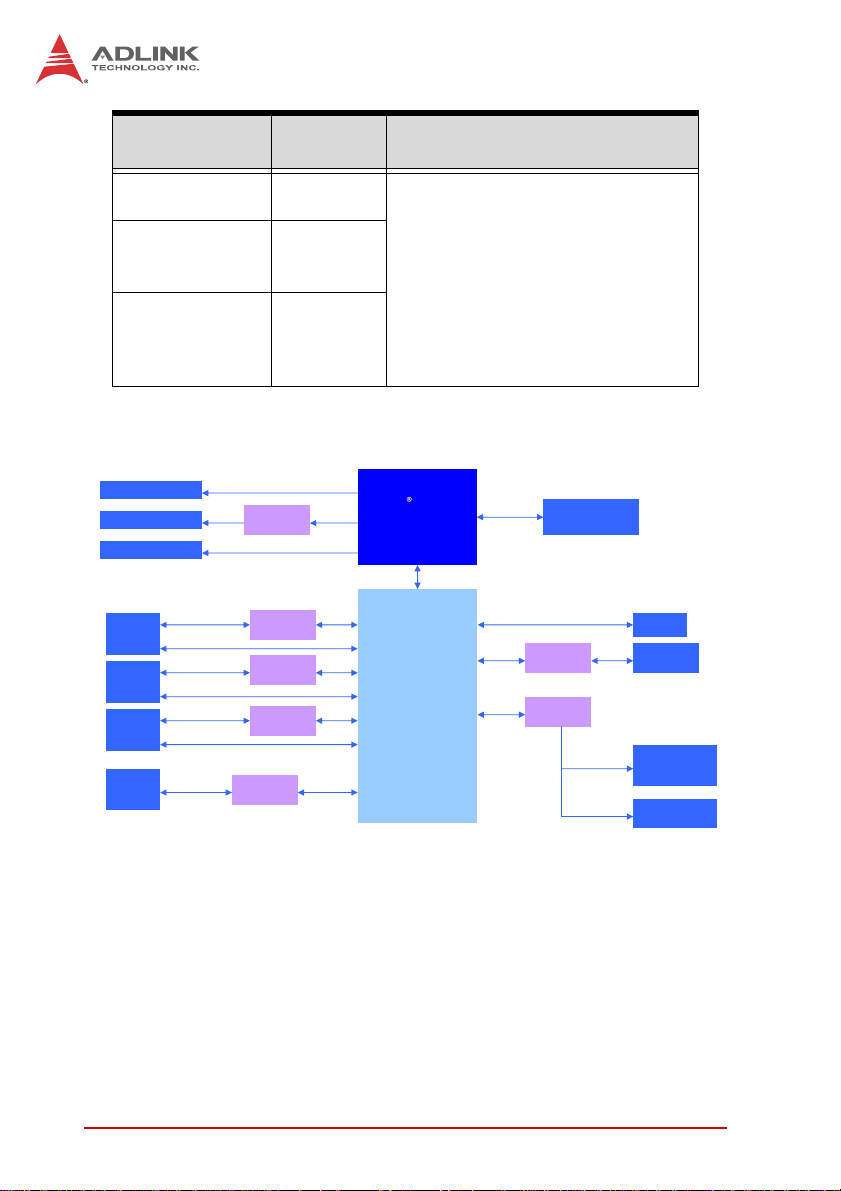
Figure 1-1: TPZ-1300 Functional Block Diagram.......................... 6
Figure 1-2: Top View..................................................................... 7
Figure 1-3: Underside View .......................................................... 8
Figure 1-4: Front View .................................................................. 8
Figure 1-5: Rear View ................................................................... 9
Figure 1-6: Side View.................................................................... 9
Figure 1-7: Front Panel I/O ........................................................... 9
Figure 1-8: Active/Link & Speed LEDs........................................ 12
Figure 1-9: Rear Panel I/O.......................................................... 14
Figure 1-10: DI/O Connector Pin Numbering................................ 16
Figure 1-11: DO Schematic .......................................................... 18
Figure 1-12: DI Schematic ............................................................ 18
Figure 1-13: Internal I/O................................................................ 19
Figure 1-14: LVDS Pin Numbering ............................................... 20
Figure 1-15: LVDS Backlight Power Connector Pin
Numbering ................................................................ 22
Figure 1-16: +3.3 V/ +5 V Voltage Internal Connectors Pin
Numbering ................................................................ 24
Figure 1-17: Reset/Power Button Extension Internal Connector
Pin Numbering.......................................................... 25
List of Figures ix
Page 10

This page intentionally left blank.
xList of Figures
Page 11

TPZ-1300
List of Tables
Table 1-1: TPZ-1300 Front Panel I/O Connector Legend.......... 10
Table 1-2: LED Indicators .......................................................... 10
Table 1-3: Active/Link LED ........................................................ 13
Table 1-4: Speed LED ............................................................... 13
Table 1-5: TPZ-1300 Rear Panel I/O Connector Legend .......... 14
Table 1-6: D-sub 9P signal name of COM1 & COM2 ports ....... 16
Table 1-7: DI/O Connector Pin Definition .................................. 17
Table 1-8: TPZ-1300 Internal I/O Legend.................................. 19
Table 1-9: LVDS Interface Connector Pin Definition ................. 21
Table 1-10: Clear CMOS Jumper ................................................ 21
Table 1-11: LVDS Backlight Power Connector Pin Definition...... 22
Table 1-12: LVDS Voltage Selected Jumper ............................... 23
Table 1-13: +3.3 V/ +5 V Voltage Internal Connectors
Pin Definition ............................................................ 24
Table 1-14: Reset/Power Button Extension Internal Connector
Pin Definitions........................................................... 25
List of Tables xi
Page 12

This page intentionally left blank.
xii List of Tables
Page 13

1 Introduction
1.1 Overview
TPZ-1300
The Topaz TPZ-1300 is the first in ADLINK’s new family of intelligent health care platforms. Based on the Intel
(TPZ-1301) and Intel
excellent computing performance and outstanding power conservation are assured. A fanless and cable-free structure provides
extended durability for long-term usage, reaulting in a noiseless
solution satisfying stringent medical application requirements. The
TPZ-1300 significantly benefits system integrators with an innovative space-saving compact configuration and rich I/O design for
maximum flexibility.
An internal PCI Express Mini Card socket and USIM slot team to
support a variety of extension functions, such as wireless connection (3G/WiFi/BT), video capture, Secure Access Modules (SAM),
and many others.
Abundant I/O interface support makes the TPZ-1300 an ideal
building block for Nursing Information, Picture Archiving Communication, Medication Automation, and Medical Administration systems, both mobile and fixed. No direct patient contact is required,
with the TPZ-1300 housed largely in a system-based locale, and
superior performance as a controller for the systems outlined
greatly benefits nursing and medical personnel in clinical environments.
The TPZ-1300 is IEC/EN-60601 certified, and ADLINK is an
ISO-13485 approved manufacturer.
®
Atom™ N2600 (TPZ-1302) processors,
®
Atom™ D2550
Introduction 1
Page 14

1.2 Features
X Energy-efficient platforms featuring Intel
D2550/N2600 processors + NM10 chipsets
X Fanless, cable-free design with extended MTBF and reli-
ability
X Medical safety IEC/EN-60601 certified
X Compact size for ease of system installation & integration
X Easy-to-clean housing
X Built-in 6 VDC to 36 VDC wide-range DC inputs(*)
X Rich I/O: 2 RS-232/422/485 + 2 RS-232, 3 GbE ports, 6
USB 2.0, 4 Digital I/O, DVI+VGA
X Extended function support from mini PCIe slots with USIM
DC power input is rated at 24VDC, with supply from 6VDC to
36VDC wide-range DC power input
®
Atom™
2Introduction
Page 15

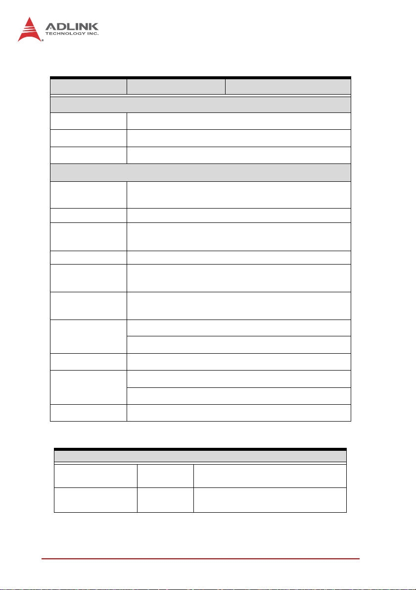
1.3 Specifications
TPZ-1301 TPZ-1302
System Core
Processor D2550 1.86GHz N2600 1.6GHz
Chipset Intel
Video DVI + VGA dual display up to 1920 x 1200
Memory
I/O Interface
®
NM10
Up to 4 GB DDR3
800/1066
Up to 2 GB DDR3 800
TPZ-1300
Ethernet 3x GbE ports (3x Intel
®
82574L)
2x software-programmable RS-232/422/485 (COM1
Serial Ports
& COM2)
2x RS-232 (COM3 & COM4)
USB 6x USB 2.0 ports
Audio 1x mic-in and 1x line-out
Expansion 1x mini PCIe slot
DI/O 4DI + 4DO
Power Supply
Built-in 6-36 V DC wide-range DC input , 3P
pluggable connector with latch (V-, GND, V+)
DC Input
* The rating of DC power input is 24VDC. The
equipment could be supplied by 6Vdc to 36Vdc
wide-range DC power input
Optional 100 W external AC-DC adapter for AC input
AC Input
SINPRO HPU101-108;
INPUT: 100-240V AC, 47-63Hz, 1.2-0.5A;
OUTPUT: 24V DC, 4.16A
Storage
SATA HDD 1 x onboard SATA port for 2.5" HDD/SSD installation
CF 1x external type I CompactFlash socket
Introduction 3
Page 16
TPZ-1301 TPZ-1302
Mechanical
Dimensions 210 (W) x 170 (D) x 53(H) mm (8.3 x 6.75 x 2.1 in.)
Weight 1.8 kg (3.98 lb)
Mounting VESA 100
Environmental
Operating
Temperature
Humidity approx. 95% @ 40°C (non-condensing)
Storage
Temperature
Storage Humidity approx. 95% @ 40°C (non-condensing)
Transport
Temperature
Standard: 0°C to 40°C (32 to 104°F) (w/ HDD)
-40°C to 85°C (-40 to 185°F)
-40°C to 85°C (-40 to 185°F)
Transport
Humidity
Vibration
EMC CE, FCC class B
Safety
Shock Operating, 50 half sine 11ms duration (w/ CF or SSD)
Power Consumption
Power off 2.16 W
System Idle 11.04 W
4Introduction
approx. 95% @ 40°C (non-condensing)
Operating, 5 G, 5-500 Hz, 3 axes (w/ CF or SSD)
Operating, 0.5 G, 5-500 Hz, 3 axes (w/ HDD)
IEC/EN 60601-1
Class I: No AP/APG No Applied Part
In shutdown status with DC input and
only USB keyboard/mouse
Under Windows Desktop with no
application programs executed
Page 17
Power Consumption
Under Windows with
Processor full load 14/15.8W
System full load 49.92 W
Recommended
power supply
80W
100% CPU utilization
/with 2D/3D graphic full load
Under Windows with
100% CPU utilization and
simultaneous access to
all I/O devices.
With consideration of voltage
de-rating under high environment
temperature.
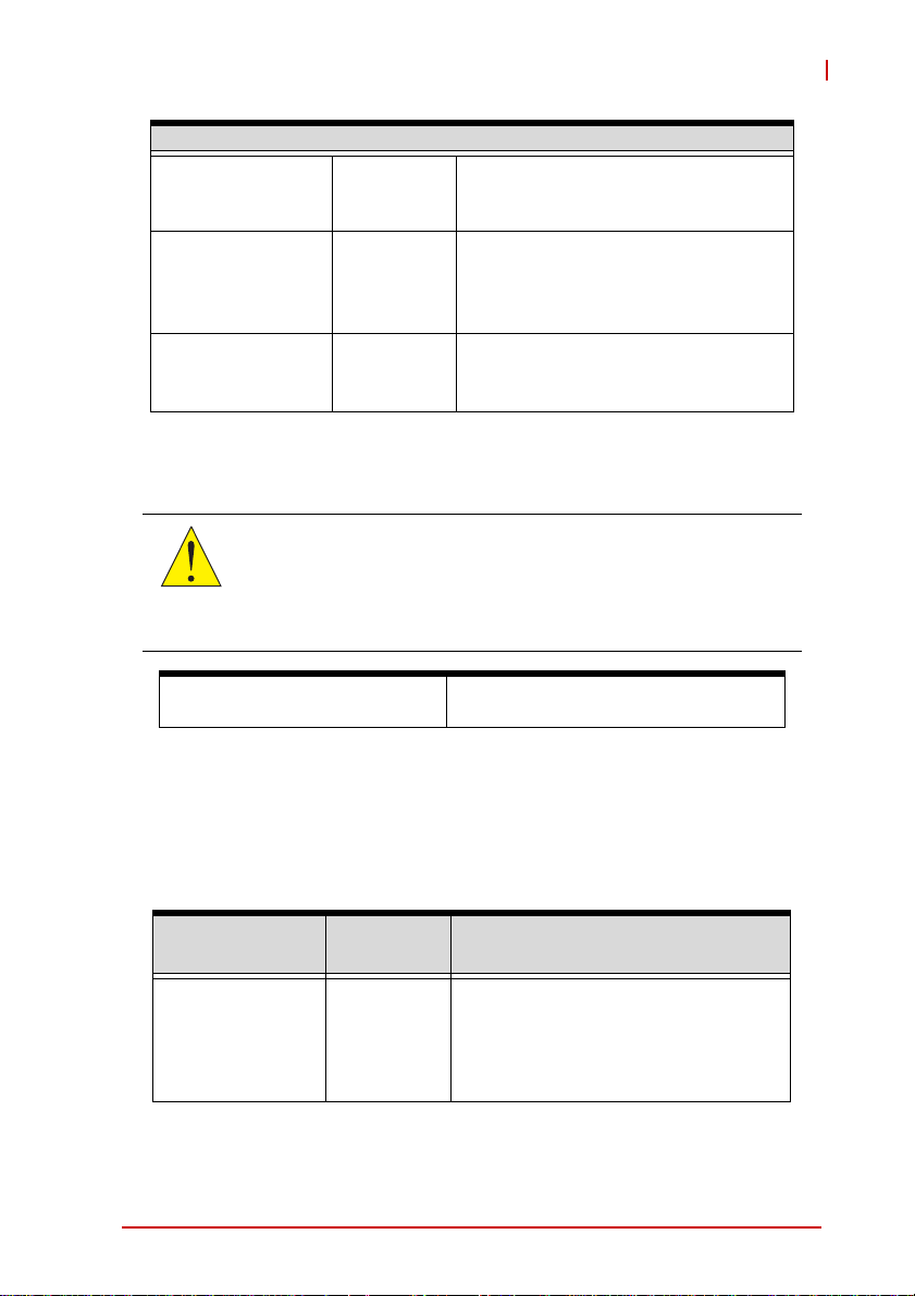
Electronic Considerations and Requirements
Electronic devices may interact due to the presence of electromagnetic radiation. A safe distance of at least one (1) meter is
CAUTION:
recccomended between devices, especially for sensitive equipment. Upon request, a table contining more detailed information is available from your dealer.
TPZ-1300
Guidance and
manufacturer’s declaration
Electromagnetic emissions
The System is intended for use in electromagnetic environments
as follows, and customers and users should ensure employment
in such an environment.
Emissions Test Compliance
RF emissions
CISPR 11
Introduction 5
Group 1
Electromagnetic
Environment–Guidance
The system uses RF energy only for
its internal function, such that RF
emissions are very low and unlikely to
cause interference with nearby
electronic equipment
Page 18
Emissions Test Compliance
RF emissions
CISPR 11
Class B
Harmonic
emissions
Class A
IEC 61000-3-2
Voltage
fluctuations/flicker
emissions
N/A
IEC 61000-3-3
Electromagnetic
Environment–Guidance
The system is suitable for use in all
establishments, including domestic
establishments and those directly
connected to the public low-voltage
power supply network provided for
domestic use
CRT Connector
DVI-D Connector
LVDS Internal Slot
RJ45 &
USB x 2
Connector
RJ45 &
USB x 2
Connector
RJ45 &
USB x 2
Connector
Line out &
Mic in
Jack
Audio
DVI
GbE I/F
USB 2.0
GbE I/F
USB 2.0
GbE I/F
USB 2.0
VGA
DVI
level shifter
LVDS
GbE controller
Intel 82574L
GbE controller
Intel 82574L
GbE controller
Intel 82574L
Realtek
ALC269Q
PCIe x1
PCIe x1
PCIe x1
HDA
Ⓡ
Atom
Intel
D2550 1.86GHz
Processor
DMI
Ⓡ
Intel
NM10
Express Chipset
DDR3
800/1066MHz
SATA II
SATA
LPC
204 pin SODIMM
JMD330 CF Card Slot
Super I/O
Figure 1-1: TPZ-1300 Functional Block Diagram
Channel A
COM serial
DIO
CF
SATA
Connector
COM Port
DB-9
Connector x4
DIO x4
Connector
6Introduction
Page 19
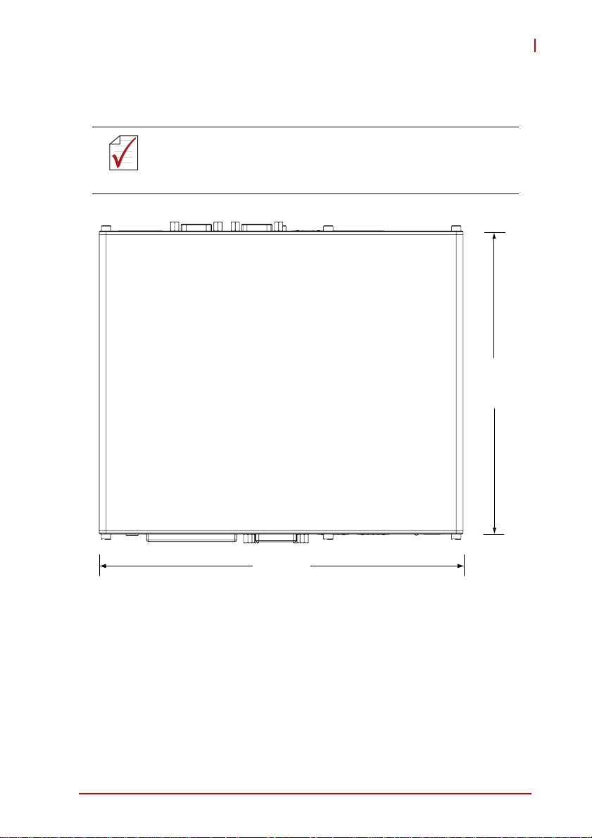
1.4 Mechanical Drawings
All dimensions shown are in millimeters (mm) unless otherwise
stated.
NOTE:
NOTE:
TPZ-1300
170
210
Figure 1-2: Top View
Introduction 7
Page 20
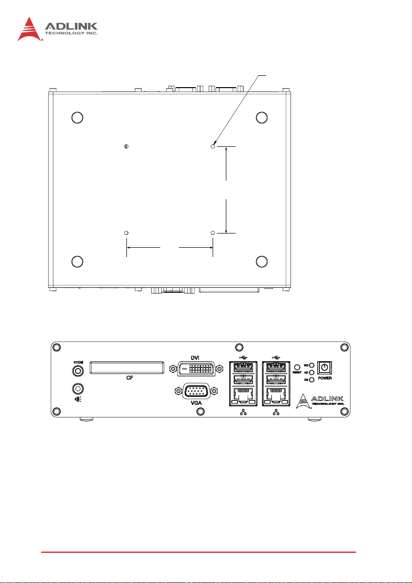
75
75
Figure 1-3: Underside View
4x-M4 THREADED
Figure 1-4: Front View
8Introduction
Page 21
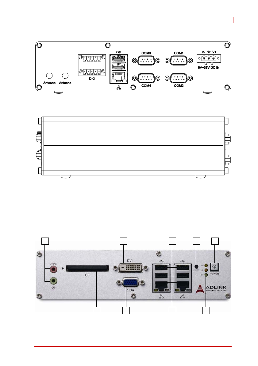
Figure 1-5: Rear View
Figure 1-6: Side View
TPZ-1300
1.5 Front Panel I/O Connectors
This section describes the I/O connectors lcoated on the front
panel of the TPZ-1300.
I
H
Figure 1-7: Front Panel I/O
Introduction 9
G
EF
CD
A
B
Page 22
A Standby Button
B LED Indicators
C Reset Button
D USB 2.0 connectors (Type A)
E Gigabit Ethernet connectors
F VGA connector
G DVI connector
H Compact-flash socket
I MIC & speaker jacks
Table 1-1: TPZ-1300 Front Panel I/O Connector Legend
1.5.1 Power Button
The power button is a non-latched push button with a blue LED
indicator. System is turned on when button is pressed, and the
power LED lit. To shut down the system, the operating system can
be issued shutdown command in or just press the power button. If
the system halts, press the button for 5 seconds also can turn off
the system compulsorily.
1.5.2 LED indicators
Besides the LED attached in the power button, there are three
LED indicators on the front panel. The following table describes
the color and function of the LED indicators.
Indicator Color Description
Watchdog (WDT) Gold
Hard disk drive Orange
Diagnostic Lime
Table 1-2: LED Indicators
10 Introduction
When Watchdog Timer is started,
flashes and lights when timer is expired.
When the SATA interface device is
active, blinks.
If no physical storage device is
connected to the system, remians lit
If no memory is installed in the
SO-DIMM sockets, blinks.
Page 23

TPZ-1300
1.5.3 Reset Button
The reset button is used to perform hard reset for the TPZ-1300.
1.5.4 VGA Connector
The TPZ-1300 provides one VGA connector for display on external (D-sub 15P) monitor.
1.5.5 DVI-D Connector
The TPZ-1300 provides one DVI-D connector for display on an
external (DVI-D) monitor.
The high impedance of long VGA/DVI cables negatively affects
video signal integrity at the receiver side.
NOTE:
NOTE:
It is recommended that VGA/DVI cables be less than 2
meters in length with effective shielding, such as UL
style 2919 AWM. If video transmission distance is to
exceed 10 meters, a VGA/DVI signal repeater or active
KVM may provide better results.
.
1.5.6 USB 2.0 Connectors
The TPZ-1300 provides a total of six USB 2.0 ports using Type A
USB connectors, with four ports on the front and two on the rear
panel. All are compatible with Hi-Speed, full-speed, and low-speed
USB devices. All USB ports share one EHCI controller, and two
USB ports share one UHCI controller. The TPZ-1300 supports
multiple boot devices, including USB flash drive, USB external
hard drive, USB floppy, USB CD-ROM and etc. The boot priority
and boot device can be configured in BIOS setting.
1.5.7 Compact-Flash Port
The TPZ-1300 is equipped with a Type I Compact-Flash socket on
the front panel. The CF interface provides +3.3V voltage to the CF
card, is transferred from SATA by an ASIC, and can act as an
alternative storage device for system installation. The TPZ-1300
can be booted up via a CF card with OS installed. When the CF
card is used as the boot device, it must be installed before system
Introduction 11
Page 24
powerup. For installation details, see “Installing a CF Card” on
page 33..
1.5.8 Gigabit Ethernet (Intel 82574L)
The TPZ-1300 provides two Gigabit Ethernet ports on the front
panel, and one on the rear, via the Intel 82574L controller. The
Ethernet controller supports the following features:
X Advanced error reporting
X Message signaled interrupts
X TCP segmentation offload/large-send support
X 802.3x flow control-compliant
X IEEE 802.1p and 802.1q support
X 10/100/1000 IEEE 802.3-compliant
X Automatic MDI/MDIX crossover at all speeds
X ACPI 2.0 specification
X Wake-On-Link feature
X Preboot eXecution Environment (PXE) flash interface sup-
port
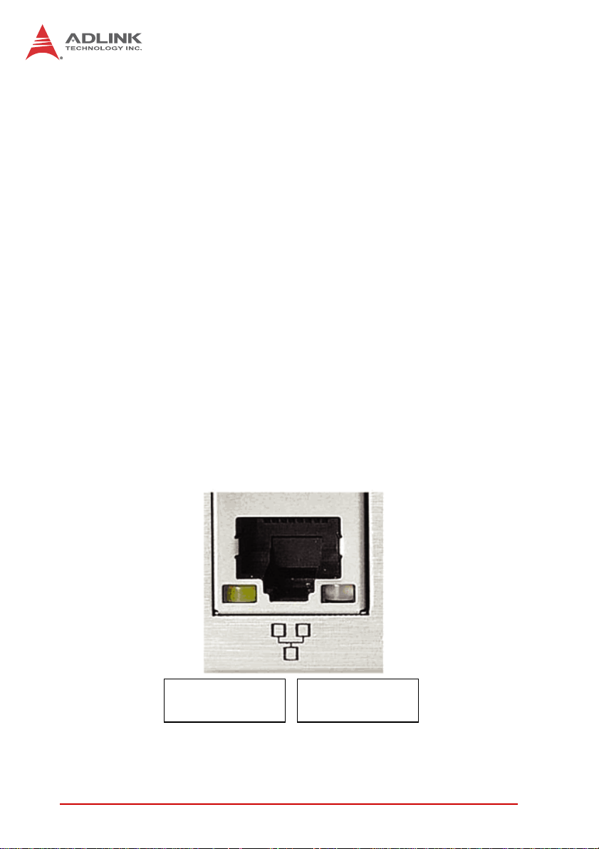
1.5.9 Active/Link & Speed LEDs
Active/Link LED
Yellow
Figure 1-8: Active/Link & Speed LEDs
12 Introduction
Speed LED
Green/Orange
Page 25

TPZ-1300
Color Status Description
OFF Ethernet port is disconnected
Yell ow
Color Status Description
Green/Orange
ON
Flashing
Ethernet port is connected and no
data transmission is underway
Ethernet port is connected and
transmitting/receiving data.
Table 1-3: Active/Link LED
OFF 10 Mbps
Green 100 Mbps
Orange 1000 Mbps
Table 1-4: Speed LED
1.5.10 MIC & Speaker Jacks
The TPZ-1300 implements Intel High Definition audio on the
REALTEK ALC269Q chip, with support up to 24-bit, 192 KHz sample rate high quality headphone output and microphone input. The
pink jack is for microphone input, and the green jack for headphone output.
Introduction 13
Page 26
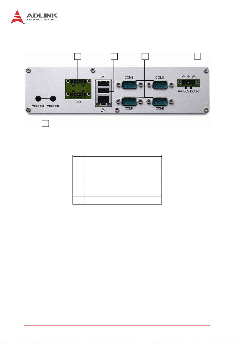
1.6 Rear Panel I/O Connectors
E
F
Figure 1-9: Rear Panel I/O
A DC power supply connector
B COM port connectors (DB9 x4)
C USB 2.0 connectors (Type A)
D Gigabit Ethernet connector
E Digital I/O connector
F Antenna connector (optional)
Table 1-5: TPZ-1300 Rear Panel I/O Connector Legend
BC
A
1.6.1 DC Power Supply Connector
The DC power supply connector consists of three pins, V+, chassis ground, and V- from right to left respectively. V+ and V- pins
are for DC power input and chassis ground pin grounds the chassis for better EMC compatibility. DC power input of the TPZ-1300
allows a voltage input range from DC 6 to 36V, with UVP (under
voltage protect of 6V), OVP (over voltage protect of 36V), and
reversed polarity protection.
DC power input is rated at 24VDC, with supply from 6VDC to
36VDC wide-range DC power input
14 Introduction
Page 27

TPZ-1300
Please ensure that DC power supply is within the input voltage
range defined in the specification, stable and low-noise, and
WARNING:
provides sufficient operating current.
Over- or under-voltage, unstable, or insufficiently powered DC
power supply may cause system instability and physical damage.
1.6.2 COM Ports
The TPZ-1300 provides 4 COM ports on the rear panel in the form
of D-sub 9P connectors, configured as follows. COM1 & COM2
ports can support RS232/RS422/RS485 mode as set in BIOS, see
“Serial Port 1~4 Configuration” on page 56..
69
15
X 2x Software-programmable RS-232/422/485 (COM1 &
COM2) by DB9 connectors
X 2x RS-232 (COM3 & COM4) by DB9 connectors
PIN
RS-232 RS-422 RS-485
1 DCD# RXD422n 485n
2 RXD RXD422p 485p
3TXDTXD422pN/S
4 DTR# TXD422n N/S
5 GND N/S N/S
6DSR# N/S N/S
Introduction 15
Signal name
Page 28

PIN
RS-232 RS-422 RS-485
7RTS# N/S N/S
8CTS# N/S N/S
9 RI# N/S N/S
Table 1-6: D-sub 9P signal name of COM1 & COM2 ports
Signal name
1.6.3 Digital I/O Connector
The TPZ-1300 provides four channel non-isolation digital input circuits and four digital non-isolation output circuits through a terminal slot of pitch 3.81mm. Spec and connector pin numbering and
definitions are as follows.
4-Channel Digital Input 4-Channel Digital Output
Output type: Open drain N-channel
Logic high: 2 to 5.25 V
Logic low: 0 to 0.8 V
MOSFET driver with internal pull high of
200
Ω resistance
Output high: 2.4 to 5 V
Output low: 0 to 0.5 V
Source/Sink current for all channels: 24 mA
610
15
Figure 1-10: DI/O Connector Pin Numbering
16 Introduction
Page 29

TPZ-1300
Pin Description Pin Description
1 DI 0 6 DO 0
2 DI 1 7 DO 1
3 DI 2 8 DO 2
4 DI 3 9 DO 3
5GND 10GND
Table 1-7: DI/O Connector Pin Definition
+5V
200 ȍ
DO
output
MOSFET
DO
GND
GND
Introduction 17
Page 30

Figure 1-11: DO Schematic
+3.3V
4.7K ȍ
MOSFET
DI
DI
input
GND
GND
Figure 1-12: DI Schematic
1.6.4 Antenna Connector
The TPZ-1300 provides two SMA type antenna connectors suitable for Wireless LAN and Wireless WAN modules of an internal
Mini PCI Express card.
18 Introduction
Page 31

1.7 Internal I/O Connectors
A
TPZ-1300
JI
G
H
F
E
B
D
C
Figure 1-13: Internal I/O
A SATA slot F Mini PCI Express slot & USIM Socket
B LVDS interface connector G Extra +3.3V voltage internal connector
C Clear CMOS jumper H Extra +5V voltage internal connector
LVDS backlight power
D
connector
LVDS voltage select
E
jumper
Table 1-8: TPZ-1300 Internal I/O Legend
Introduction 19
I Reset button extend internal connector
J Power button extend internal connector
Page 32

1.7.1 SATA Slot
The TPZ-1300 provides a Gen 2 SATA port at 3.0 Gbit/s, compatible with SATA Gen 1 1.5Gbit/s. The SATA host controller supports
legacy mode using I/O space and AHCI mode using memory
space. This SATA connector accepts 2.5” and 3.5” (optional) HDD
or solid state disk (SSD). The disk must be installed in the SATA
connector with a HDD bracket. For installation information, see
“Installing a Hard Disk Drive” on page 28..
1.7.2 LVDS Interface Connector (optional)
The TPZ-1300 provides an internal LVDS interface connector,
supporting single channel up to 1366*768 24-bit resolution, with
pin numbering and definition as follows.
1 2
Figure 1-14: LVDS Pin Numbering
20 Introduction
Page 33

Pin Signal Pin Signal
1 +LVDS_VCC 2 +LVDS_VCC
3GND 4GND
5 LVDS_CLK+ 6 LVDS_TXP2
7 LVDS_CLK- 8 LVDS_TXN2
9GND 10GND
11 LVD S_TX P0 12 LV DS_TXP3
13 LVDS_TXN0 14 LVDS_TXN3
15 GND 16 GND
17 LVDS_TXP1 18 LVDS_DCLK
19 LVDS_TXN1 20 LVDS_DDAT
Table 1-9: LVDS Interface Connector Pin Definitio n
1.7.3 Clear CMOS Jumper
TPZ-1300
Upon encountering an abnormal condition preventing the
TPZ-1300 from booting, the jumper can clear the BIOS content
stored in CMOS and restore default settings. To clear CMOS,
short pin #2 to pin #3 of JP1 and then return to normal mode (short
pin #1 to pin #2).
Normal Clear
Table 1-10: Clear CMOS Jumper
Introduction 21
Page 34

1.7.4 LVDS Backlight Power Connector (optional)
The TPZ-1300 internal LVDS backlight power connector supports
+5V and +12V, with numbering and pin definitions as follows.
1
Figure 1-15: LVDS Backlight Power Connector Pin Numbering
Pin Description
1 +5V
2 Backlight Enable
3 Backlight Control
4 GND
5 +12V
T able 1-11: L VDS Backlight Power Connector Pin Definition
22 Introduction
Page 35

TPZ-1300
1.7.5 LVDS Voltage Selected Jumper (optional)
The TPZ-1300 can support +3.3V and +5V for the LVDS power
panel, with power of the LVDS interface (+LVDS_VCC) selected
by internal jumper. default jumper setting is 5 V, as follows.
+L VDS_VCC: +5V +LVDS_VCC: +3.3V
2
T able 1-12: LVDS Voltage Selected Jumper
2
1.7.6 Mini PCI Express Slot & USIM Socket
The TPZ-1300 features a Mini PCI Express slot providing functional expansion with, for example, wireless LAN module, wireless
WAN module, GPS module, and others. Conforms to PCI Express
Mini Card Electromechanical Specification Revision 1.2.
The USIM Socket allows a wireless WAN module for wireless
communication with a telecom operator, connected to a Mini PCI
Express module. SIM card and Wireless WAN module can be
installed to facilitate wireless wide area network communication.
1.7.7 Extra +3.3 V/ +5 V Voltage Internal Connectors
Internal +3.3V and +5V connectors support up to 1A current of
+3.3V and +5V to the Mini PCI Express card if needed, such as for
wireless WAN or GPS card. Pin numbering and definition are as
follows.
Introduction 23
Page 36

1234
Figure 1-16: +3.3 V/ +5 V Voltage Internal Connectors Pin Numbering
Pin Description
1+5V
2GND
3 +3.3V
4GND
Table 1-13: +3.3 V/ +5 V Voltage Internal Connectors Pin Definition
1.7.8 Reset/Power Button Extension Internal Connector
Internal reset and power button extension connectors extend
power and reset button function to external controllable devices,
with pin numbering and definition of the two connectors as follows.
24 Introduction
Page 37

TPZ-1300
1
2
3
4
Figure 1-17: Reset/Power Button Extension Internal Connector
Pin Numbering
Pin Description
1 Power button
2GND
3 Reset button
4GND
Table 1-14: Reset/Power Button Extension Internal Connector Pin
Definitions
Introduction 25
Page 38

This page intentionally left blank.
26 Introduction
Page 39

2 Getting Started
2.1 Unpacking Checklist
Before unpacking, check the shipping carton for any damage. If
the shipping carton and/or contents are damaged, inform your
dealer immediately. Retain the shipping carton and packing
materials for inspection. Obtain authorization from your dealer
before returning any product to ADLINK. Ensure that the following items are included in the package.
X TPZ-1300
X Screw pack for wall-mounting and HDD installation
X User’s Manual
X ADLINK All-in-One DVD
TPZ-1300
Getting Started 27
Page 40

2.2 Installing a Hard Disk Drive
For safety, installation or replacement of a Hard Disk Drive
should only be performed by qualified service personnel.
CAUTION:
Before installing a hard disk drive, remove the bottom cover of the
chassis as follows.
1. Use a #3 hex wrench to unscrew all 6 M3 hex bolts from
the front panel.
2. Remove the 4 fixing members from the front panel and
remove the panel.
28 Getting Started
Page 41

TPZ-1300
3. Remove the 6 screws from the rear panel.
4. Remove the 8 fixing members from the rear panel and
remove the panel.
5. Invert the unit and lift the bottom housing off the top
chassis.
6. The TPZ-1300 ships with an attached empty HDD
bracket. Unscrew the 4 screws and remove the HDD
bracket.
Getting Started 29
Page 42

7. Use the 4 M3-F head screws provided to fix a 2.5” HDD
or SSD to the bracket.
8. Connect the 2.5’’ HDD or SSD to the SATA connector.
30 Getting Started
Page 43

TPZ-1300
9. Fasten the 4 screws to fix the HDD bracket to the fixing
members.
Getting Started 31
Page 44

10.Align the sliding parts as shown and reassemble the bottom chassis to the top chassis.
11.Reinstall and refasten the 12 M3 hex bolts and 12 fixing
members into the front and rear panels.
32 Getting Started
Page 45

TPZ-1300
2.3 Installing a CF Card
The TPZ-1300 series provides a CompactFlash socket on the
front panel to accommodate one CF card. A SATA HDD or SSD
and CF card can further be simultaneously installed, and boot
device preferences set in the BIOS. To install the CF card:
1. Remove and rotate the CF cover to expose the slot.
2. Gently insert the CF card into the CF socket.
3. Rotate the CF cover to its original position and replace.
Getting Started 33
Page 46

2.4 Connecting DI/O Device
The TPZ-1300 series controller provides 4 digital input and 4 digital output ports. The two pluggable terminals provided enable connection to the DI/O device.
Connect the two pluggable terminals to the DI/O connector on the
rear panel. Fix the pluggable terminal using the 2 screws.
For DI/O pin definitions, see “Digital I/O Connector” on page 16..
34 Getting Started
Page 47

TPZ-1300
2.5 Connecting DC power
Before providing DC power to the TPZ-1300, ensure voltage
and polarity provided are compatible with the DC input.
WARNING:
The TPZ-1300 DC power input connector utilizes V+, V- , and
chassis ground pins, and accepts input voltage as discussed.
Connect the DC power connector and fix using the 2 screws.
Improper input voltage and/or polarity can be responsible for
system damage.
Getting Started 35
Page 48

2.6 Wall-mounting the TPZ-1300
The TPZ-1300 is shipped with a VESA 100 wall-mount brackets
and accessory screws. The bracket has four M4 mounting holes
with a pitch of 100 mm, allowing fixture to any VESA 100 compatible mounting mechanism. The mounting bracket enables the
TPZ-1300 series controller to be mounted on a wall or the back of
a monitor. To wall-mount the TPZ-1300:
1. Prepare the wall-mount brackets and 4 M4 screws provided.
36 Getting Started
Page 49

TPZ-1300
2. Fasten the 4 screws to fix the bracket to the desired
mounting surface (wall or monitor) as shown.
Getting Started 37
Page 50

3. Fasten the 4 dedicated mounting screws provided into
the holes on the bottom of the TPZ-1300.
38 Getting Started
Page 51

TPZ-1300
4. Depress the TPZ-1300 until a click is heard. The chassis
is now locked to the mounting bracket. All four orientations are supported, depending on the user’s requirments.
2.7 Cooling Configuration
Heat-generating components of the TPZ-1300 (such as CPU and
PCH) are all situated on the left side of the system. These components directly contact the heat sink via thermal pads and dissipate
heat generated by the components. To maximize efficiency of heat
dissipation, maintain a minimum of 2 inches (5 cm) clearance on
the top of the TPZ-1300.
Getting Started 39
Page 52

This page intentionally left blank.
40 Getting Started
Page 53

3 Driver Installation
After installing the operating system, all related drivers must be
installed for the system to function properly. This section describes
the drivers needed for Windows operating systems and the
procedures to install them. For other OS support, please contact
ADLINK for further information.
Install drivers as follows.
1. Fully install Microsoft Windows OS before installing any
drivers. Most standard I/O device drivers have been
included in Microsoft Windows OS. For Windows 7
users, please note that you need Administrator privilege
to install the drivers properly.
2. Install the chipset driver.
3. Install the graphics driver.
4. Install the Ethernet driver.
5. Install the audio driver.
6. Install the WDT (watchdog timer) driver.
7. Install the DI/O driver.
TPZ-1300
3.1 Installing the chipset driver
This section describes installation of the chipset driver for the
TPZ-1300. The chipset driver directs the operating system to configure the Intel
the following features function properly:
X SATA Storage Support
X USB Support
X Identification of Intel
Manager
Microsoft Windows 7 must be fully installed and running on the
system before installing this software:
Driver Installation 41
®
NM10 chipset components in order to ensure that
®
Chipset Components in the Device
Page 54

The following steps install the chipset driver for the TPZ-1300
1. Close any running applications.
2. Insert the ADLINK All-in-One DVD. The chipset driver is
located in the directory
x:\Driver Installation\Topaz\TPZ-1300\Chipset
where x: denotes the DVD-ROM drive.
3. Execute Setup.exe and follow onscreen instructions to
complete the setup.
4. After installation is complete, reboot the system.
3.2 Installing the graphics driver
This section describes installation of the graphics driver for the
TPZ-1300. The TPZ-1300 is equipped with the Intel
Media Accelerator Driver package, which supports Windows 7.
To install the graphics driver:
1. Close any running applications.
2. Insert the ADLINK All-in-One DVD. The graphics driver
is located in the directory
x:\Driver Installation\Topaz\TPZ-1300\Graphics
where x: denotes the DVD-ROM drive.
3. Execute Setup.exe and follow onscreen instructions to
complete the setup.
4. After installation is complete, reboot the system.
®
Graphics
3.3 Installing the Ethernet driver
This section describes installation of the Ethernet driver for the
TPZ-1300. To install the driver for the Intel 82547 Gigabit Ethernet
controller:
1. Close any running applications.
2. Insert the ADLINK All-in-One DVD. The Ethernet driver
is located in the directory
42 Driver Installation
Page 55

TPZ-1300
x:\Driver Installation\Topaz\TPZ-1300\LAN-Intel\
where x: denotes the DVD-ROM drive.
3. Execute setup.exe and follow onscreen instructions to
complete the setup.
4. After installation is complete, reboot the system.
3.4 Installing the audio driver
This section describes installation of the audio driver for the
TPZ-1300. The TPZ-1300 supports High Definition audio using the
Realtek ALC269 audio codec. To install the audio driver:
1. Close any running applications.
2. Insert the ADLINK All-in-One DVD. The audio driver is
located in the directory
x:\Driver Installation\Topaz\TPZ-1300\Audio\
where x: denotes the DVD-ROM drive.
3. Execute Setup.exe and follow onscreen instructions to
complete the setup.
4. After installation is complete, reboot the system.
3.5 Installing the WDT and DI/O drivers
A WDT (watchdog timer) is a hardware mechanism resetting the
system when the operating system or application is halted. A typical usage of WDT is to start the timers and periodically reset the
timer, and when timer is expired, the system resets. The WDT
driver must be installed to program the WDT.
The TPZ-1300 also provides 4 channel DI and 4 channel DO.
WDT and DI/O Driver/ API driver packages must be installed to
access and use the DI/O feature.
To install the WDT and DI/O drivers for the TPZ-1300:
Close any running applications.
Ensure you have Administrator privilege.
Download Microsoft
x86 or x64 version from: http://www.microsoft.com/en-us/download/details.aspx?id=3387
Driver Installation 43
®
Visual C++ 2005 Redistributable Package
Page 56

Insert the ADLINK All-in-One DVD. The WDT driver is located in
the directory:
x:\Driver Installation\Topaz\TPZ-1300\WDT_DI/O\
where x denotes the DVD-ROM drive.
Run Setup.exe and follow the onscreen instructions to complete
setup.
After complete installation, reboot the system.
WDT, DI/O API library and sample programs are located in the
TPZ1300_WDT folder, default location of “C:\Program
Files\ADLINK\TPZ1300_WDT”
Administrator privilege is required to use the WDT API in
Windows 7.
NOTE:
NOTE:
44 Driver Installation
Page 57

Appendix A: Watchdog Timer (WDT) &
DI/O Function Libraries
This appendix describes use of the watchdog timer (WDT) function library for the TPZ-1300.
The watchdog timer is a hardware mechanism provided to reset
the system if the operating system or an application stalls. After
starting, the watchdog timer in the application must be periodically
reset before the timer expires. Once the watchdog timer expires, a
hardware-generated signal is sent to reset the system.
DI/O provides input/output to support inter-device communications. Simple programming guides allow easy transmission of digital signals between the system and attached peripherals.
A.1 WDT with API/Windows
Topaz WDT API library files and a demo program (incl. source
code) can be found on the included driver CD or downloaded from
http://www.adlinktech.com.
To use the WDT function library for TPZ-1300 series, include the
header file WDT.h and linkage library WDT.lib in the C++ project.
TPZ-1300
InitWDT
Initializes watchdog timer function of TPZ-1300. InitWDT must
be called before the invocation of any other WDT function.
@ Syntax
C/C++
BOOL InitWDT()
@ Parameters
None
@ Return code
TRUE if watchdog timer is successfully initialized.
FALSE if watchdog timer fails to initialize.
Watchdog Timer (WDT) & DI/O Function Libraries 45
Page 58

SetWDT
Sets the timeout value of the watchdog timer. There are two
parameters for this function to indicate the timeout ticks and
unit. ResetWDT or StopWDT should be called before the expiration of watchdog timer, or the system will reset.
@ Syntax
C/C++
BOOL SetWDT(BYTE tick, BYTE unit)
@ Parameters
tick
Specify the number of ticks for watchdog timer. A valid value
is 1 - 255.
unit
Specify the timeout ticks of the watchdog timer.
Value Description
The unit for one tick is one second. For example, when one
0
tick is specified as 100 and the unit as 0, the timeout value is
100 seconds.
The unit for one tick is one minute. For example, whenone
1
tick is specified as 100 and the unit as 1, the timeout value is
100 minutes.
@ Return codes
TRUE if timeout value of watchdog timer is successfully set.
FALSE if timeout value of watchdog timer is failed to set.
StartWDT
Starts watchdog timer function. Once the StartWDT is invoked,
the watchdog timer starts. ResetWDT or StopWDT should be
called before the expiration of watchdog timer, or the system
will reset.
@ Syntax
C/C++
46 Watchdog Timer (WDT) & DI/O Function Librarie s
Page 59

BOOL StartWDT()
@ Parameters
None
@ Return codes
TRUE if watchdog timer is successfully started.
FALSE if watchdog timer is failed to start.
ResetWDT
Resets the watchdog timer. The invocation of ResetWDT
allows restoration of the watchdog timer to the initial timeout
value specified in SetWDT function. ResetWDT or StopWDT
should be called before the expiration of the watchdog timer, or
the system will reset.
@ Syntax
C/C++
BOOL ResetWDT()
@ Parameters
None
@ Return codes
TRUE if watchdog timer is successfully reset.
TPZ-1300
FALSE if watchdog timer fails to reset.
StopWDT
Stops the watchdog timer.
@ Syntax
C/C++
BOOL StopWDT()
@ Parameters
None
@ Return codes
TRUE if watchdog timer is successfully stopped.
Watchdog Timer (WDT) & DI/O Function Libraries 47
Page 60

FALSE if watchdog timer fails to stop.
A.2 DI/O with API/Windows
Topaz DI/O API library files and a demo program (incl. source
code) are located on the included driver CD or downloaded from
http://www.adlinktech.com.
DI/O functions are as follows.
GPIO_Init
Reserves system resources for digital input/output API service.It is necessary to call this function before using other TPZ1300 DI/O functions.
@ Syntax
C/C++
I16 GPIO_Init(void)
@ Parameters
None
@ Return code
NoError
ErrorOpenDriverFailed
ErrorDeviceIoctl
GPI_Read()
Reads the digital logic state of the digital input line..
@ Syntax
C/C++
I16 GPI_Read(U16 *pwState)
@ Parameters
pwState
Returns the digital logic state of TPZ-1300 digital input channels 1~4 (bit 0~3)
@ Return code
48 Watchdog Timer (WDT) & DI/O Function Librarie s
Page 61

NoError
ErrorOpenDriverFailed
ErrorDeviceIoctl
GPO_Write()
Sets the digital logic state of the digital output line.
@ Syntax
C/C++
I16 GPO_Write(U16 wState)
@ Parameters
State
Sets the digital logic state of TPZ-1300 digital output channels
1~4 (bit 0~3) to 0 or 1.
@ Return code
NoError
ErrorOpenDriverFailed
ErrorDeviceIoctl
TPZ-1300
GPO_Read()
Reads the digital logic state of the digital output line.
@ Syntax
C/C++
I16 GPO_Read(U16 *pwState)
@ Parameters
pwState
Returns the digital logic state of TPZ-1300 digital output channels 1~4 (bit 0~3).
@ Return code
NoError
ErrorOpenDriverFailed
ErrorDeviceIoctl
Watchdog Timer (WDT) & DI/O Function Libraries 49
Page 62

This page intentionally left blank.
50 Watchdog Timer (WDT) & DI/O Function Librarie s
Page 63

Appendix B: BIOS Setup
BIOS options in the manual are for reference only, and are
subject to configuration. Users are welcome to download the
NOTE:
NOTE:
The Basic Input/Output System (BIOS) is a program that provides
a basic level of communication between the processor and
peripherals. In addition, the BIOS also contains codes for various
advanced features applied to the TPZ-1300. The BIOS setup
program includes menus for configuring settings and enabling
features of the TPZ-1300 series. Most users do not need to use
the BIOS setup program, as the TPZ-1300 ships with default
settings that work well for most configurations.
WARNING:
latest BIOS version from the ADLINK website.
Changing BIOS settings may lead to incorrect controller behavior and possible inability to boot. In such a case, Section 1.7.3
on page 21 provides instruction on clearing the CMOS and
restoring default settings
TPZ-1300
BIOS Setup 51
Page 64

B.1 Main
Contains basic system information for the TPZ-1300.
B.1.1 BIOS Information
BIOS Vendor: Provider of the BIOS code
Core Version
BIOS Version: Current BIOS version
B.1.2 PC Health Status
Indicates CPU Temperature and voltages for CPU, VGFX,
+1.05V, +3.3V, +1.5V, +5V, +12.0V, VBAT.
B.1.3 System Time/System Date
This option changes the system time and date. Highlight System Time or System Date using the up or down <Arrow> keys.
52 BIOS Setup
Page 65

Enter new values using the keyboard then press <Enter> key.
Press the < Tab > key to move between fields. The date must
be entered in MM/DD/YY format. The time is entered in
HH:MM:SS format.
The time is in 24-hour format. For example, 5:30 A.M.
appears as 05:30:00, and 5:30 P.M. as 17:30:00.
NOTE:
NOTE:
B.2 Advanced
Setting incorrect or conflicting values in Advanced BIOS
Setup may cause system malfunction
CAUTION:
Accesses advanced options of the TPZ-1300.
TPZ-1300
BIOS Setup 53
Page 66

B.2.1 CPU Configuration
Displays:
X Processor Type
X EMT64 Support
X Processor Speed
X System Bus Speed
X Ratio Status
X Actual Ratio
X Processor Stepping
X Microcode Revision
X L1 Cache RAM
X L2 Cache RAM
X Processor Core
X Hyper-threading Support
54 BIOS Setup
Page 67

TPZ-1300
And settings for
Hyper-Threading
Enabled for Windows XP and Linux (OS is optimized for HyperThreading Technology) and disabled for other OS (OS not optimized for Hyper-Threading Technology).
Execute Disable Bit
Enabled in XP, can prevent certain classes of malicious buffer
overflow attacks when combined with a supporting OS.
Limit CPUID Maximum
Disabled for Windows XP.
BIOS Setup 55
Page 68

B.2.2 Onboard Device Configuration
Serial Port 1~4 Configuration
Port type (RS-232/422/485) is controllable for Serial Ports 1 and 2
only.
Launch Intel 82574 LAN PXE OpROM
Enables/Disables execution of LAN boot-rom to add boot option
for legacy network devices LAN 1, LAN 2, and LAN 3, respectively.
SATA Controller(s)
Enables/Disables internal serial ATA controller.
SATA Mode Selection
Allows selection of SATA channel configuration, from IDE Mode or
AHCI Mode
56 BIOS Setup
Page 69

TPZ-1300
Legacy USB Support
Enables Legacy USB Support, with AUTO disabling if no USB
devices are connected, and DISABLE maintaining USB devices
available only for EFI applications.
B.2.3 Advanced Power Management
Restore AC Power Loss
Determines the state the computer will enter when power is
restored after a power loss, from among Last State, Power On and
Power Off, as follows
Option Description
Power Off
Power On
BIOS Setup 57
When enabled, powers off the system when
power is restored.
When enabled, powers on the system when
power is restored.
Page 70

Option Description
When enabled, powers the system off or on
Last State
depending on the previous system power
state while power is restored.
System Watchdog
Enables/disables system internal watchdog to prevent boot failure
at system POST stage.
Wake System With Fixed Time
Enables/disables system wake on alarm event.
Wake On Ring
Enables/disables system wake on RI event.
B.2.4 SATA Configuration
58 BIOS Setup
Page 71

Displays status ionformation for:
SATA Port
CF Port
And allows setting of CF Port Hot Plug.
B.2.5 Serial Port Console Redirection
TPZ-1300
Provides redirection and settings for SOL (Serial Over LAN)
COMs 1 to 4.
Also displays current status of miscellaneous parameters for COM
Ports.
As well, the following Serial Port for Out-of-Band Management/
EMS settings can be made:
BIOS Setup 59
Page 72

Console Redirection
Enables Console Redirection function for remote management of
a Windows Server OS through the port selected by Out-of-Band
Mgmt Port.
Out-of-Band Mgmt Port
Selects the COM Port for remote management of a Windows OS.
Terminal Type
Selects the transmission protocol for remote terminal console.
B.3 Chipset
Primary IGFX Boot Display
Selects the video device to be activated during POST.
60 BIOS Setup
Page 73

Active LFP
Selects the Active LFP configuration.
B.4 Boot
TPZ-1300
Setup Prompt Timeout
Sets the number of seconds for the setup activation key (“DEL”) to
remain active.
Bootup Num-Lock State
Allows the Number Lock setting to be modified during boot.
Quiet Boot
When disabled, BIOS displays POST messages, and when
enabled, BIOS displays the OEM logo.
BIOS Setup 61
Page 74

Fast Boot
When disabled, BIOS performs all POST tests. When enabled,
BIOS to skips selected POST tests to boot faster.
While enabling Fast Boot can reduce the ready time of system,
some startup parameters will be assumed and may not func-
NOTE:
NOTE:
tion as expected.
Boot Option Priorities
Specifies the priority of boot devices. All installed boot devices are
detected during POST and displayed. Selection of the target Boot
Option # selects the desired boot device.
Hard Drive BBS Priorities
Selects the HDD to be displayed in the Boot Option Priorities listing when multiple HDD are present.
62 BIOS Setup
Page 75

B.5 Security
TPZ-1300
If only the Administrator’s password is set, only access to Setup is
limited and requests the password. If only User’s password is set,
the password is requested at power up to boot or enter Setup, in
which the user is grated Administrator rights.
Administrator Password
Sets Setup Administrator password
User Password
Sets Boot/Setup User password
BIOS Setup 63
Page 76

B.6 Save & Exit
Discard Changes and Exit
Discards all changes and exits BIOS setup.
Save Changes and Reset
Saves all changes and reboots the system to activate new settings.
Discard Changes
Resets system setup without saving any changes.
Restore Defaults
Resets all BIOS options to the complete default settings. Default
settings, while designed for maximum system stability, may impact
64 BIOS Setup
Page 77

TPZ-1300
performance. Restore Defaults Setup is indicated if the computer
encounters system configuration problems.
Save as User Defaults
Saves all changes made as user defaults.
Restore User Defaults
Restores the user defaults to all setup options.
Launch EFI Shell from filesystem device
Attempts to launch an EFI Shell application (Shellx64.efi) from one
available filesystem device.
BIOS Setup 65
Page 78

This page intentionally left blank.
66 BIOS Setup
Page 79

TPZ-1300
Important Safety Instructions
For user safety, please read and follow all instructions,
WARNINGS, CAUTIONS, and NOTES marked in this manual
and on the associated equipment before handling/operating the
equipment.
To avoid risk of electric shock, the device can only be connected to supply mains with protective grounding
WARNING:
There is risk of explosion if the included Lithium battery is
replaced with an incorrect type. Dispose of used batteries
WARNING:
WARNING:
CAUTION:
according to instructions
Do not modify the device without authorization of the manufacturer
To avoid damage or malfunction, only clean the product with a
soft dry cloth, moistened if necessary, and, in extreme use, a
neutral cleansing agent
Waste Disposal:
While this device is provided by an environmentally
aware manufacturer that complies with the WEEE, it
may contain substances that could be harmful to the
environment if disposed of in non-compliant environments. Please be environmentally responsible and
recycle this product through your local recycling facility at its completion of service.
X Please keep this manual for future reference
X The DC connector provides isolation and disconnect from
supply mains
Important Safety Instructions 67
Page 80

X One AC input is provided and serves as a disconnect. Dis-
connect the device from both AC outlets via these inputs
before servicing or cleaning. Always use a damp cloth for
cleaning
X For devices requiring electrical connection to mains, ensure
that a suitable supply outlet is located near the device's
installed location and is easily accessible
X Protect the device from excess humidity
X Ensure a stable surface is provided when installing, drops
or falls can cause injury
X Ensure compatibility of power source voltage when con-
necting the device
X Situate the power supply cord so as to prevent tripping and
snagging and keep the cord uncovered
X Note all cautions and warnings on the device and accompa-
nying documentation
X If the equipment unused for extended periods, disconnect
from the mains to avoid damage from transient overvoltage
X Keep all liquids away from device openings to prevent fire
or electrical shock
X Never open the device housing. The device should only be
opened by qualified service personnel
X If any of the following arises, have the device checked by
service personnel immediately:
Z The power cord or plug is damaged
Z Liquid has entered the device
Z The device has been exposed to moisture
Z The device malfunctions or fails to function according to
the User‘s Manual
Z The device is dropped or damaged
Z The device shows obvious signs of breakage or damage
X The device can be operated at a maximum ambient temper-
ature of 40ºC
X Restrictions specified on other equipment or NETWORK/
DATA COUPLINGS, other than those forming part of an ME
68 Important Safety Instructions
Page 81

TPZ-1300
SYSTEM, to which a SIGNAL INPUT/OUTPUT PART may
be connected (Per manufacturer’s declaration all SIP/SOP
are for exclusive connection to IEC 60601-1 certified equipment when it is placed within the patient environment and to
IEC 60601-1 certified equipment when it is outside of the
patient environment.)
Important Safety Instructions 69
Page 82

This page intentionally left blank.
70 Important Safety Instructions
Page 83

Getting Service
Contact us should you require any service or assistance.
ADLINK Technology, Inc.
Address: 9F, No.166 Jian Yi Road, Zhonghe District
New Taipei City 235, Taiwan
ᄅקؑխࡉ৬ԫሁ 166 ᇆ 9 ᑔ
Tel: +886-2-8226-5877
Fax: +886-2-8226-5717
Email: service@adlinktech.com
Ampro ADLINK Technology, Inc.
Address: 5215 Hellyer Avenue, #110, San Jose, CA 95138, USA
Tel: +1-408-360-0200
Toll Free: +1-800-966-5200 (USA only)
Fax: +1-408-360-0222
Email: info@adlinktech.com
ADLINK Technology (China) Co., Ltd.
Address: Ϟ⍋Ꮦ⌺ϰᮄᓴ∳催⾥ᡔು㢇䏃 300 ো(201203)
300 Fang Chun Rd., Zhangjiang Hi-Tech Park,
Pudong New Area, Shanghai, 201203 China
Tel: +86-21-5132-8988
Fax: +86-21-5132-3588
Email: market@adlinktech.com
ADLINK Technology Beijing
Address: ࣫ҀᏖ⍋⎔Ϟഄϰ䏃 1 োⲜ߯ࡼ E ᑻ 801 ᅸ(100085)
Rm. 801, Power Creative E, No. 1, B/D
Shang Di East Rd., Beijing, 100085 China
Tel: +86-10-5885-8666
Fax: +86-10-5885-8625
Email: market@adlinktech.com
TPZ-1300
ADLINK Technology Shenzhen
Address: ⏅ഇᏖቅ⾥ᡔು催ᮄϗ䘧᭄ᄫᡔᴃು
Tel: +86-755-2643-4858
Fax: +86-755-2664-6353
Email: market@adlinktech.com
ADLINK Technology (Europe) GmbH
Address: Nord Carree 3, 40477 Duesseldorf, Germany
Tel: +49-211-495-5552
Fax: +49-211-495-5557
Email: emea@adlinktech.com
A1 2 ὐ C (518057)
2F, C Block, Bldg. A1, Cyber-Tech Zone, Gao Xin Ave. Sec. 7,
High-Tech Industrial Park S., Shenzhen, 518054 China
Getting Service 71
Page 84

ADLINK Technology, Inc. (French Liaison
Off
Address: 15 rue Emile Baudot, 91300 Massy CEDEX, France
Tel: +33 (0) 1 60 12 35 66
Fax: +33 (0) 1 60 12 35 66
Email: france@adlinktech.com
ADLINK Technology Japan Corporation
Address: ͱ101-0045 ᵅҀ䛑ҷ⬄⼲⬄䤯ފ⬎ 3-7-4
⼲⬄ 374 ɛɳ 4F
KANDA374 Bldg. 4F, 3-7-4 Kanda Kajicho,
Chiyoda-ku, Tokyo 101-0045, Japan
Tel: +81-3-4455-3722
Fax: +81-3-5209-6013
Email: japan@adlinktech.com
ADLINK Technology, Inc. (Korean Liaison Office)
Address: 昢殾柢 昢爎割 昢爎壟 1675-12 微汾瘶捒娯 8猻
8F Mointer B/D,1675-12, Seocho-Dong, Seocho-Gu,
Seoul 137-070, Korea
Tel: +82-2-2057-0565
Fax: +82-2-2057-0563
Email: korea@adlinktech.com
ADLINK Technology Singapore Pte. Ltd.
Address: 84 Genting Lane #07-02A, Cityneon Design Centre,
Singapore 349584
Tel: +65-6844-2261
Fax: +65-6844-2263
Email: singapore@adlinktech.com
ADLINK Technology Singapore Pte. Ltd. (Indian Liaison Office)
Address: 1st Floor, #50-56 (Between 16th/17th Cross) Margosa Plaza,
Margosa Main Road, Malleswaram, Bangalore-560055, India
Tel: +91-80-65605817, +91-80-42246107
Fax: +91-80-23464606
Email: india@adlinktech.com
ice)
ADLINK Technology, Inc. (Israeli Liaison Office)
Address: 6 Hasadna St., Kfar Saba 44424, Israel
Tel: +972-9-7446541
Fax: +972-9-7446542
Email: israel@adlinktech.com
72 Getting Service
 Loading...