

Page 1
STC-15W04
Smart Touch Computer
User’s Manual
Manual Rev.: 0.20 Preliminary
Revision Date: Dec. 26, 2014
Part No: 50-1Z201-1000
Advance Technologies; Automate the World.
Page 2

Revision History
Revision Release Date Description of Change(s)
0.10 8/12/2014 Preliminary release
0.20 26/12/2014
Remove driver install section; update packing list;
add OS support
ii Revision History
Page 3

STC-15W04
Preface
Copyright 2014 ADLINK Technology Inc.
This document contains proprietary infor mation protected by copyright. All rights are reserved. No part of this manual may be reproduced by any mechanical, electronic, or other means in any form
without prior written permission of the manufacturer.
Disclaimer
The information in this document is subject to change without prior
notice in order to improve reliability, design, and function and does
not represent a commitment on the part of the manufa cturer.
In no event will the manufacturer be liable for direct, indirect, special, incidental, or consequential damages arising out of the use or
inability to use the product or documentation, even if advised of
the possibility of such damages.
Environmental Responsibility
ADLINK is committed to fulfill its social responsibility to global
environmental preservation through compliance with the European Union's Restriction of Hazardous Substances (RoHS) directive and Waste Electrical and Electronic Equipment (WEEE)
directive. Environmental protection is a top priority for ADLINK.
We have enforced measures to ensure that our products, manufacturing processes, components, and raw materials have as little
impact on the environment as possible. When products are at their
end of life, our customers are encouraged to dispose of them in
accordance with the product disposal and/or recovery programs
prescribed by their nation or company.
Trademarks
Product names mentioned herein are used for identification purposes only and may be trademarks and/or registered trademarks
of their respective companies.
Preface iii
Page 4
Conventions
Take note of the following conventions used throughout this
manual to make sure that users perform certain tasks and
instructions properly.
Additional information, aids, and tips that help users perform
tasks.
NOTE:
NOTE:
Information to prevent minor physical injury, component damage, data loss, and/or program corruption when trying to com-
CAUTION:
WARNING:
plete a task.
Information to prevent serious physical injury, component
damage, data loss, and/or program corruption when trying to
complete a specific task.
iv Preface
Page 5

STC-15W04
Table of Contents
Revision History...................................................................... ii
Preface.................................................................................... iii
List of Figures....................................................................... vii
List of Tables.......................................................................... ix
1 Introduction ........................................................................ 1
1.1 Overview.............................................................................. 1
1.2 Features............................................................................... 1
1.3 Package Contents ............................................................... 2
1.4 Block Diagram ..................................................................... 3
1.5 Mechanical Dimensions....................................................... 4
2 System Description............................................................ 5
2.1 Specifications....................................................................... 5
2.2 I/O Panel Layout.................................................................. 6
2.3 Pin Definitions...................................................................... 7
3 Getting Started ................................................................. 11
3.1 Panel Mounting.......................... ... ... .... ... ... ... ... .... ... ... ... .... . 11
3.2 Connecting Power ............................................................. 13
3.3 CFast Card Installation ...................................................... 14
3.4 CMOS Battery Replacement ............................................. 15
3.5 Driver Installation................................................. ... ... ... .... . 17
4 BIOS................................................................................... 19
4.1 Introduction........................................................................ 19
4.2 Starting the BIOS.......................... ... .... ... ... ... ... .... ... ... ... ..... 19
4.3 Main Setup.......... ... .... ... ... ... .... ... ... ... .... .............................. 24
4.4 Advanced BIOS Setup....................................................... 25
Table of Contents v
Page 6

4.4.1 PCI Subsystem Settings................................................26
4.4.2 CPU Configuration.........................................................27
4.4.3 Thermal Configuration..................... .... ... ... ... ... .... ... ... ... .29
4.4.4 IDE Configuration ..........................................................32
4.4.5 USB Configuration.........................................................34
4.4.6 Super IO Configuration..................................................36
4.4.7 IT8781F Hardware Monitor............................................38
4.4.8 PPM Configuration.................. ... ... ... .... ... .......................39
4.5 Chipset Configuration ........................................................ 41
4.5.1 Host Bridge Configuratio................................................42
4.5.2 South Bridge Configuration............................................44
4.6 Boot Settings ..................................................................... 46
4.7 Security Setup.................................................................... 49
4.8 Save & Exit Menu .............................................................. 50
Important Safety Instructions............................................... 55
Getting Service...................................................................... 57
vi Table of Contents
Page 7

STC-15W04
List of Figures
Figure 1-1: STC-15W04 Block Diagram............................................. 3
Figure 1-2: STC-15W04 Dimensions ................................................. 4
Figure 2-1: STC-15W04 Rear I/O Layout........................................... 6
List of Figures vii
Page 8

This page intentionally left blank.
viii List of Figures
Page 9

STC-15W04
List of Tables
Table 2-1: Specifications.............................. .... ... ... ... ... .... ... ... ... .... ... . 6
Table 2-2: RJ-45 GbE Pin Definitions............................................... 7
Table 2-3: LAN LED Status Definitions.............................................7
Table 2-4: USB 2.0 Port Pinout......................................................... 8
Table 2-5: RS-485 Port Pinout.. ... ... .... ... ... ... .... ... ... ... ... .... ... ... ... .... ... . 8
Table 2-6: CFast Socket Pin Definition.............................................9
Table 2-7: COM2 Pinout................................................................. 10
List of Tables ix
Page 10

This page intentionally left blank.
xList of Tables
Page 11

1 Introduction
1.1 Overview
The STC series of Smart Touch Computers is designed for industrial automation and other applications in harsh or hazardous environments requiring an IP65 compliant front bezel with projected
capacitive multi-touch display. Typical applications include industrial control systems for the food and beverage industries; marine,
oil and gas industries; automated buildings; transportation; hospitals; factories; and leisure facilities.
1.2 Features
X TFT flat panel display with 16.7M colors and LED backlight
X 15.6" display, 16:9 aspect ratio, 1366x768 resolution
X 300 nits (w/o touch screen attached), 500:1 typical contrast
ratio
X Projected capacitive multi-touch display
X Intel® Atom™ Processor D2550 with Intel® NM10 Express
Chipset
X DDR3 SO-DIMM up to 4GB
X 2x USB 2.0 ports, 2x GbE ports, 1x RS-485
X Externally accessible CFast card slot
X Supports panel mounting
X IP65 rated front panel
X 24 VDC power input
STC-15W04
Introduction 1
Page 12

1.3 Package Contents
Please check that your package contains the items below. If you
discover damaged or missing items, please contact your vendor.
X STC-15W04 Smart Touch Computer
X Panel mount bracket kit
X 8GB CFast card with OS pre-installed
DO NOT install or apply power to equipment that is damaged
or if there is missing/incomplete equipment. Retain the ship-
WARNING:
ping carton and packing materials for inspection. Please contact your ADLINK dealer/vendor immediately for assistance.
Obtain authorization from your dealer before returning any
product to ADLINK.
2Introduction
Page 13
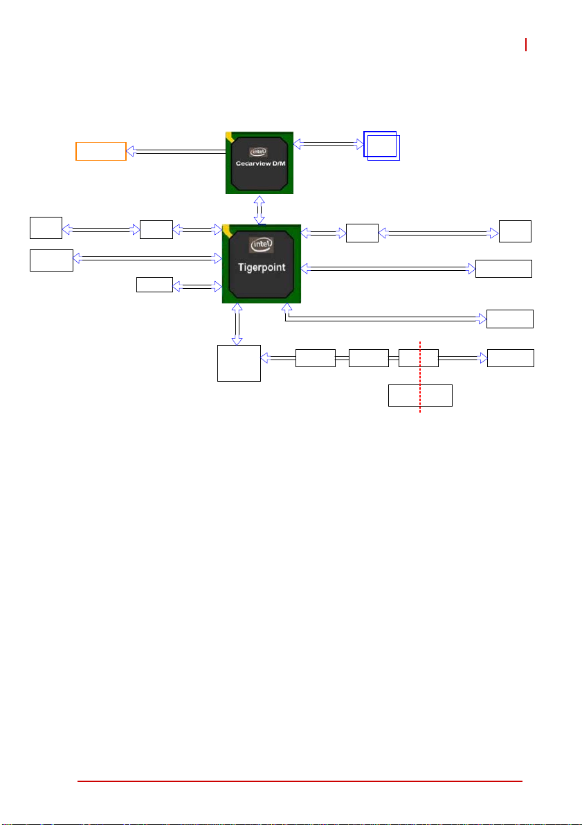
1.4 Block Diagram
STC-15W04
RJ-45
USB Conn
LCD Display
GbE 1
Single Channel 24-bit
Realtek
8111E
USB 3/4
SPI ROM
LVDS
PCIe x1
SPI
Super IO
IT8781F
D2550
DMI x 4
NM10
LPC
UART 1
Single Channel
DDR3 1067MT/s
PCIe x1
USB 7
SATA 1
SP3243
Realtek
8111E
SP3238 ISO3086 RS-485
Figure 1-1: STC-15W04 Block Diagram
GbE 2
5V 5V_ISO
5V to 5V
isolaon
RJ-45
Touch Controller
CFast
Introduction 3
Page 14
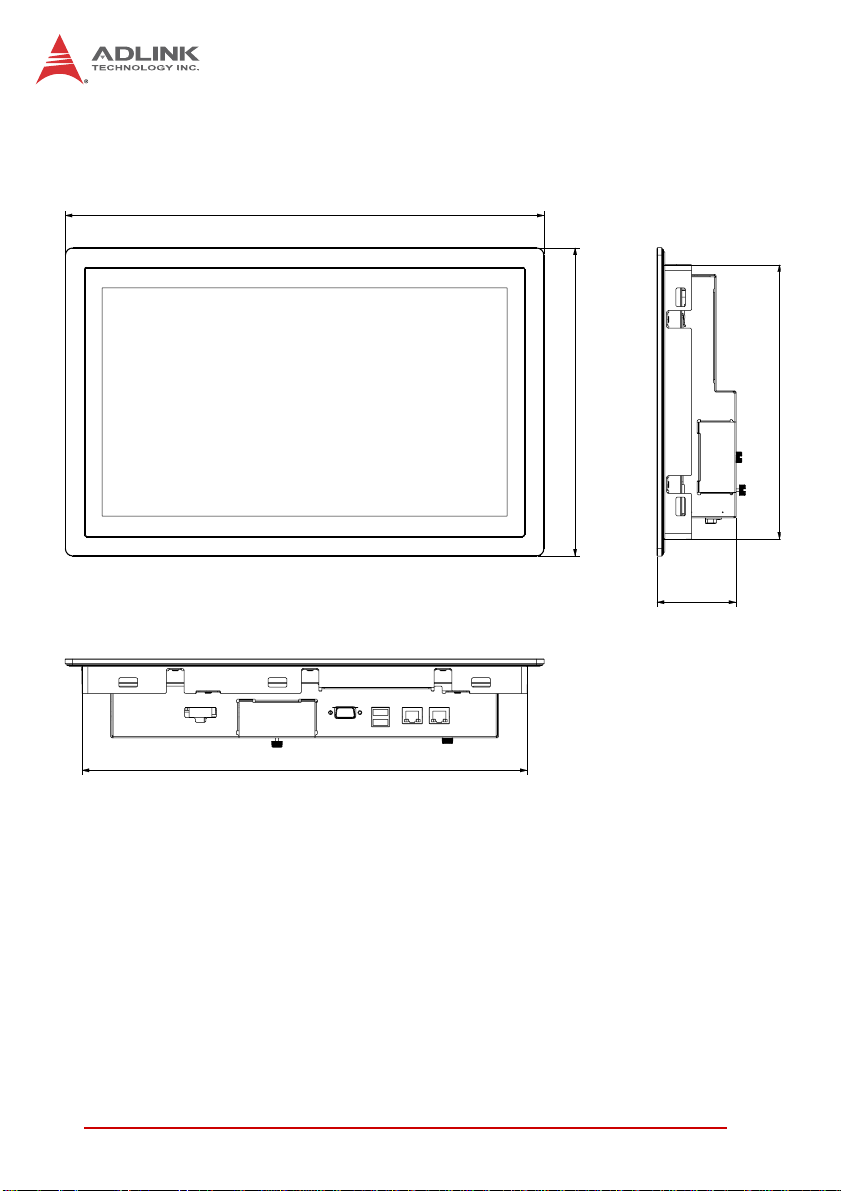
1.5 Mechanical Dimensions
407.3
378.5
Dimensions in mm
Figure 1-2: STC-15W04 Dimensions
262.3
233.5
67.2
4Introduction
Page 15

STC-15W04
2 System Description
2.1 Specifications
Display
Display Size 15.6”
Resolution 1366x768 pixels
Brightness 300 nits (w/o touchscreen)
Contrast Ratio 500:1 typical
Touchscreen
Processor Intel® Atom™ Processor D2550
Chipset Intel® NM10 Express Chipset
Memory 2GB DDR3 SO-DIMM (max. 4GB)
Storage Industrial CFast card (default 8GB)
I/O
Operating System Windows 7 Professional 32-bit (pre-installed)
Construction Anodized aluminum front bezel and steel chassis
Weight 5.5 kg (12.1 lb)
Dimensions (WxHxD) 407.3 x 262.3 x 67.2 mm
Mounting Panel mount (cut-out: 380 x 235 mm)
Temperature
Relative Humidity 95% non-condensing
Vibration EN 60068-2-6 (1G, 10Hz~500Hz
Shock IEC 60068-2-27 (15G, 11ms)
Ingress Rating IP65 front panel, IP20 rear enclosure
Certifications &
Compliance
EMC
Projected capacitive full-flat multi-touch display
(glass)
System Components
2x USB 2.0 ports
2x GbE ports (2x Realtek 8111E)
1x RS-485 port (isolated)
Mechanical
Environmental
Operating: 0°C to 50°C
Storage: -20°C to 60°C
CE (IEC 61010-2-201)
UL 508 + CSA-C22.2 No. 142
cUL and UL C1D2 (UL 1604)
IEC Ex XX T4 (IEC 60079-15, IEC 60079-0)
CE (EN 61000-6-2, EN 61000-6-4)
FCC (Part 15 Subpart B)
System Description 5
Page 16
Input Voltage
24VDC ±15%, connector with locking mechanism,
protective earth connection
Power Consumption 40W
Table 2-1: Specifications
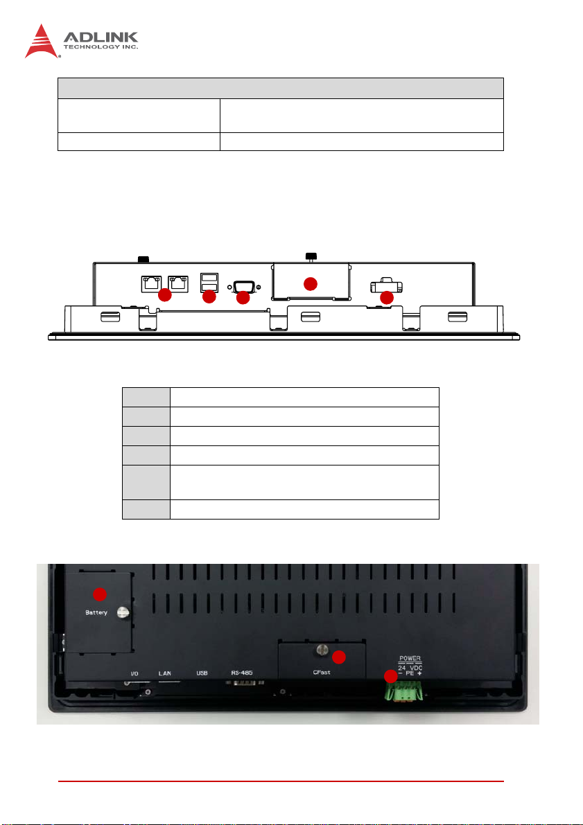
2.2 I/O Panel Layout
Bottom View
Power
Rear View
6
1
2
3
4
Figure 2-1: STC-15W04 Rear I/O Layout
1 GbE ports
2 USB 2.0 ports
3 RS-485 port (isolated)
4 CFast card slot access
24 VDC power inlet (w/ polarization protection,
5
protective earth connection)
6 CMOS battery access
4
5
5
6System Description
Page 17
2.3 Pin Definitions
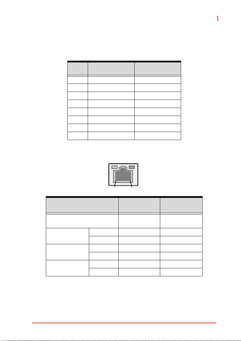
RJ-45 Gigabit Ethernet Connectors
STC-15W04
Pin #
1 TX+ GBE1/2_MDI0+
2 TX- GBE1/2_MDI03 RX+ GBE1/2_MDI1+
4 — GBE1/2_MDI2+
5 — GBE1/2_MDI26 RX- GBE1/2_MDI17 — GBE1/2_MDI3+
8 — GBE1/2_MDI3-
Table 2-2: RJ-45 GbE Pin Definitions
Status
Network link is not established
or system powered off
10 Mbps
100 Mbps
1000 Mbps
10BASE-
T/100BASE-TX
Speed
Link OFF ON
Active OFF Blinking
Link Green ON
Active Green Blinking
Link Orange ON
Active Orange Blinking
Activity
8
1
Speed LED
(Green/Orange)
OFF OFF
1000BASE-T
Activity LED
(Yellow)
Table 2-3: LAN LED Status Definitions
System Description 7
Page 18
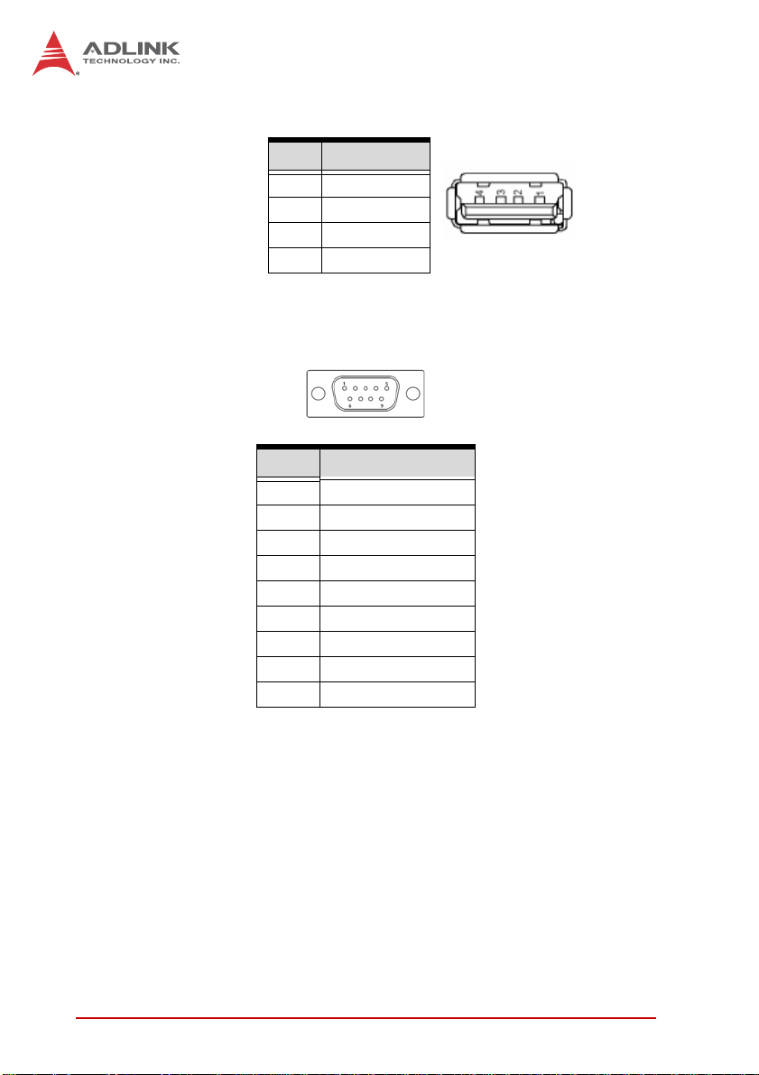
USB Connector
Pin # Signal Name
1Vcc
2UV03UV0+
4GND
Table 2-4: USB 2.0 Port Pinout
RS-485 Port (isolated)
Pin 1
Pin 6
Pin 5
Pin 9
Pin No RS-485
Pin1 DATA+
Pin2 DATAPin3 NC
Pin4 NC
Pin5 GND
Pin6 NC
Pin7 NC
Pin8 NC
Pin9 NC
Table 2-5: RS-485 Port Pinout
8System Description
Page 19

CFast Socket
Pin # Signal Name
Ground S1
SATA_TX-P S2
SATA_TX-N S3
Ground S4
SATA_RX-N S5
SATA_RX-P S6
Ground S7
CFast_CDI P1
Ground P2
NC P3
NC P4
NC P5
NC P6
Ground P7
CFast_LED1 P8
CFast_LED2 P9
NC P10
NC P11
NC P12
P3V3 P13
P3V3 P14
Ground P15
Ground P16
CFast_CDO P17
STC-15W04
S1
1
P1
24
Table 2-6: CFast Socket Pin Definition
System Description 9
Page 20
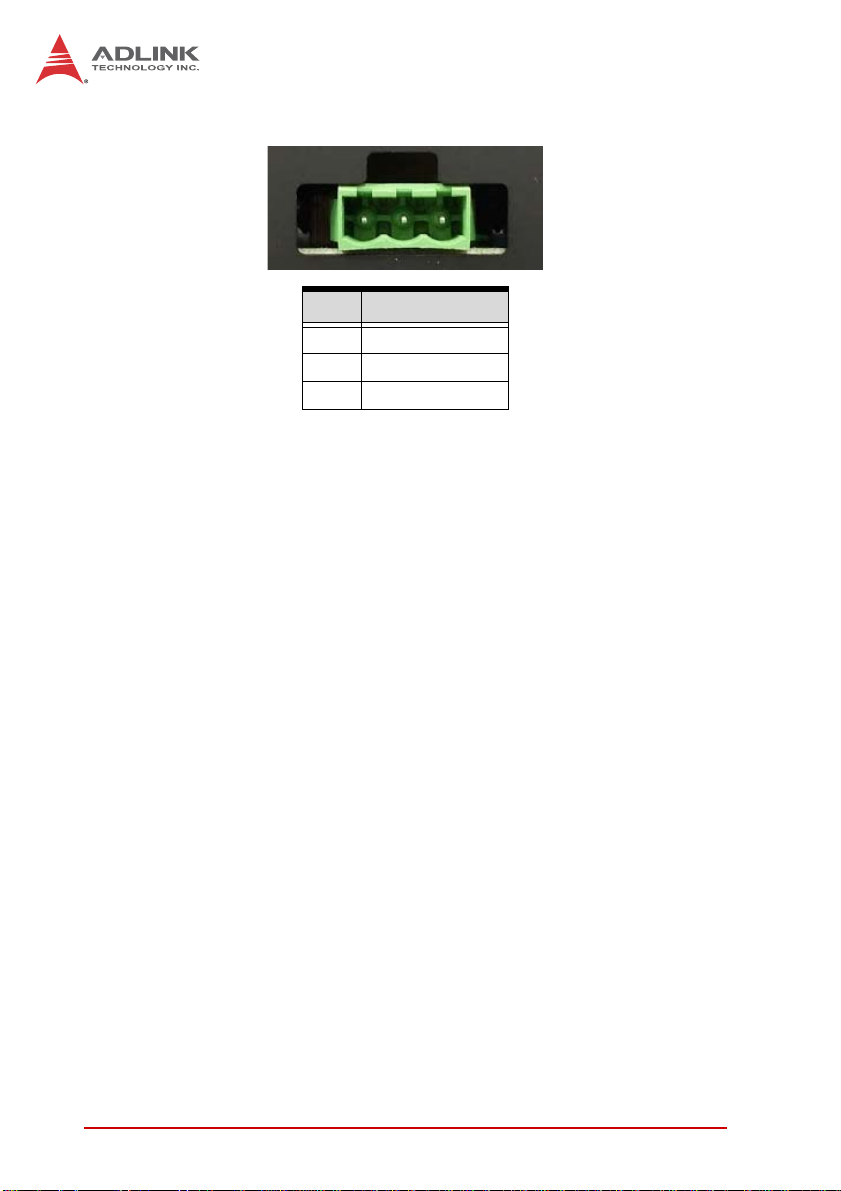
DC Power Input Connector
Pin 1
Pin # Signal
1Vin2 Earth Ground
3Vin+
Table 2-7: DC Power Input Pinout
10 System Description
Page 21

3 Getting Started
3.1 Panel Mounting
The STC-15W04 can be panel mounted using the 10 brackets
included with the device. Make sure there is adequate space
behind the panel for ventilation, and that the panel material and
thickness can support the weight of the device.
The mounting brackets can accommodate a maximum panel
thickness of 4mm.
NOTE:
NOTE:
1. Cut the panel opening using the appropriate cutout
dimensions: 380 x 235 mm.
2. Attach I/O cables to the device before installing into the
panel if rear access will be limited after installation (see
“I/O Panel Layout” on page 6.).
3. Place the device into the panel cutout.
4. Insert the mounting brackets into the slots on the sides
of the device as shown below.
STC-15W04
Getting Started 11
Page 22

5. Hand-tighten the mounting brackets with a Phillips-head
screwdriver to secure it to the panel. Do not overtighten
the brackets to avoid damaging the device enclosure.
Do not overtighten the brackets as this may damage the device
enclosure.Always tighten the mounting brackets BY HAND to
CAUTION:
12 Getting Started
secure it to the panel.
Page 23

STC-15W04
3.2 Connecting Power
Insert the positive and negative leads from the power supply as
marked on the chassis into the pluggable terminal block included
with the device.
Insert the pluggable terminal block into the 3-pole connector on
the I/O panel of the device. The device will power up when the
power supply is turned on.
Make sure the power supply is turned OFF when handling the
power leads.
WARNING:
Getting Started 13
Page 24

3.3 CFast Card Installation
To install or remove the CFast card, loosen the captive screw until
it is possible to remove the CFast slot cover.
Do not completely remove the screw, as this will make it more
difficult to remove the slot cover.
NOTE:
NOTE:
Insert or remove the CFast card as required.
Replace the slot cover and tighten the scew.
14 Getting Started
Page 25

STC-15W04
3.4 CMOS Battery Replacement
To change the CMOS backup battery, loosen the captive screw
until it is possible to remove the battery socket cover.
Do not completely remove the screw, as this will make it more
difficult to remove the slot cover.
NOTE:
NOTE:
Getting Started 15
Page 26

Replace the CMOS battery with one of the same type (CR2450).
Replace the slot cover and tighten the scew.
16 Getting Started
Page 27

4 BIOS
4.1 Introduction
The following chapter describes basic navigation for the AMI EFI
BIOS setup utility.
4.2 Starting the BIOS
To enter the setup screen, follow these steps:
1. Power on the motherboard
2. Press the < Delete > key on your keyboard when you
see the following text prompt:
< Press DEL to run Setup >
3. After you press the < Delete > key, the main BIOS setup
menu displays. You can access the other setup screens
from the main BIOS setup menu , such as Chipset and
Power menus.
STC-15W04
Note: In most cases, the < Delete > key is used to invoke the setup
screen. There are several cases that use other keys, such as
< F1 >, < F2 >, and so on.
BIOS 19
Page 28

Setup Menu
The main BIOS setup menu is the first screen that you can navigate. Each main BIOS setup menu option is described in this
user’s guide.
The Main BIOS setup menu screen has two main frames. The left
frame displays all the options that can be configured. “Grayed”
options cannot be configured, “Blue” options can be.
The right frame displays the key legend. Above the key legend is
an area reserved for a text message. When an option is selected
in the left frame, it is highlighted in white. Often a text message will
accompany it.
Navigation
The BIOS setup/utility uses a key-based navigation system called
hot keys. Most of the BIOS setup utility hot keys can be used at
any time during the setup navigation process.
20 BIOS
Page 29

NOTE:
NOTE:
STC-15W04
There is a hot key legend located in the right frame on most
setup screens.
The < F8 > key on your keyboard is the Fail-Safe key. It is not displayed on the key legend by default. To set the Fail-Safe settings
of the BIOS, press the < F8 > key on your keyboard. It is located
on the upper row of a standard 101 keyboard. The Fail-Safe settings allow the motherboard to boot up with the least amount of
options set. This can lessen the probability of conflicting settings.
Hotkey Descriptions
Enter The < Enter > key allows you to display or change the setup
option listed for a particular setup item. The < Enter > key
can also allow you to display the setup sub-screens.
F1 The < F1 > key allows you to display the General Help
screen. Press the < F1 > key to open the General Help
screen.
BIOS 21
Page 30

F2 The < F2 > key on your keyboard is the previous values key.
It is not displayed on the key legend by default. To set the
previous values settings of the BIOS, press the < F2 > key
on your keyboard. It is located on the upper row of a standard 101 keyboard. The previous values settings allow the
motherboard to boot up with the least amount of options set.
This can lessen the probability of conflicting settings.
F3 The < F3 > key on your keyboard is the optimized defaults
key. To set the optimized defaults settings of the BIOS, press
the < F3 > key on your keyboard. It is located on the upper
row of a standard 101 keyboard. The optimized defaults se ttings allow the motherboard to boot up with the optim ized defaults of options set. This can lessen the probability of
conflicting settings.
F4 The < F4 > key allows you to save any changes you have
made and exit Setup. Press the < F10 > key to save your
changes. The following screen will appear:
22 BIOS
Page 31

STC-15W04
Press the < Enter > key to save the configuration and exit.
You can also use the < Arrow > key to select Cancel and
then press the < Enter > key to abort this function and return
to the previous screen.
ESC The < Esc > key allows you to discard any changes you have
made and exit the Setup. Press the < Esc > key to exit the
setup without saving your changes. The following screen will
appear:
Press the < Enter > key to discard changes and exit. You can
also use the < Arrow > key to select Cancel and then press
the < Enter > key to abort this function and retu rn to the previous screen.
BIOS 23
Page 32

4.3 Main Setup
When you first enter the Setup Utility , you will enter the Main setup
screen. You can always return to the Main setup screen by selecting the Main tab. There are two Main Setup options. They are
described in this section. The Main BIOS Setup screen is shown
below.
System & Board Info
The Main BIOS setup screen reports BIOS version, BIOS build
date and time, and total memory.
System Time/System Date
Use this option to change the system time and date. Highlight System Time or System Date using the < Arrow > keys. En ter new values using the keyboard. Press the < Tab > key or the < Arrow >
keys to move between fields. The date must be entered in MM/
DD/YY format. The time is entered in HH:MM:SS format.
The time is in 24-hour format. For example, 5:30 A.M. appears
as 05:30:00, and 5:30 P.M. as 17:30:00.
NOTE:
NOTE:
24 BIOS
Page 33

STC-15W04
4.4 Advanced BIOS Setup
Select the Advanced tab from the setup screen to enter the
Advanced BIOS Setup screen. You can select any of the items in
the left frame of the screen, such a s SuperIO Conf iguration, to go
to the sub menu for that item. You can display an Advanced BIOS
Setup option by highlighting it using the < Arrow > keys. The
Advanced BIOS Setup screen is shown below.
The sub menus are described on the following pages.
Watchdog Timer Timeout Watchdog function configuration. Set this value to Disabled,
30 sec, 60 sec, 120 sec.
BIOS 25
Page 34

4.4.1 PCI Subsystem Settings
PCI Latency Timer
Value to be programmed into PCI Latency Timer Register.
Options: 32 PCI Bus Clocks, 64 PCI Bus Clocks, 96 PCI Bus
Clocks, 128 PCI Bus Clocks, 160 PCI Bus Clocks, 192 PCI Bus
Clocks, 224 PCI Bus Clocks, 248 PCI Bus Clocks.
VGA Palette Snoop
Enables or Disables VGA Palette Registers Snooping. Set this
value to Disabled, Enabled
26 BIOS
Page 35

STC-15W04
PERR# Generation
Enables or Disables PCI Device to Generate PERR#. Set this
value to Disabled, Enabled
SERR# Generation
Enables or Disables PCI Device to Generate SERR#. Set this
value to Disabled, Enabled
4.4.2 CPU Configuration
You can use this screen to select options for the CPU Configuration Settings. Use the up and down < Arrow > keys to select an
item. Use the < + > and < - > keys to change the value of the
selected option. A description of the selected item appears on the
right side of the screen. The settings are described on the following pages. An example of the CPU Configuration screen is shown
below.
Hyper-Threading
Enables/disables Hyper-Threading Technology. Enable for
Windows XP and Linux (OS optimized for Hyper-Threading
BIOS 27
Page 36

Technology) and disable for other OS (OS not optimized for
Hyper-Threading Technology.
Execute Disable Bit
Execute Disable Bit can prevent certain classes of malicious
buffer overflow attacks when combined with a supporting OS
(Windows Server 2003 SP1, Windows XP SP2, SuSE Linux
9.2, RedHat Enterprise 3 Update 3.) Set this value to Disabled,
Enabled.
Limit CPUID Maximum Disabled for Windows XP. Set this value to Disabled, Enabled.
28 BIOS
Page 37

4.4.3 Thermal Configuration
CPU Thermal Configuration
STC-15W04
DTS SMM
Disabled: ACPI thermal management uses EC re ported tem-
perature values. Enabled: ACPI thermal management uses
DTS SMM mechanism to obtain CPU temperature values. Out
of Spec: ACPI Thermal Management uses EC reported temperature values and DTS SMM is used to handle Out of Spec
condition. Set this value to Disabled, Enabled, Critical Temp
Reporting (out of spec).
BIOS 29
Page 38

Platform Thermal Configuration
Critical Trip Point
This value controls the temperature of the ACPI Critical Trip
Point - the point at which the OS will shut the system off. Note:
100C is the Plan Of Record (POR) for all Intel mobile processors. Set this value to POR, 15C, 23C, 31C, 39C, 47C, 55C,
63C, 71C, 79C, 87C, 95C, 103C, 111C, 119C, 127C.
Active Trip Point Lo Fan Speed
This value controls the temperature of the ACPI Active Trip
Point - the point in which the OS will turn the processor fan on
low. Set this value to Disabled, 15C, 23C, 31C, 39C, 47C,
55C, 63C, 71C, 79C, 87C, 95C, 103C, 111C, 119C.
Active Trip Point Hi Fan Speed
This value controls the temperature of the ACPI Active Trip
Point - the point in which the OS will turn the processor fan on
high. Set this value to Disabled, 15C, 23C, 31C, 39C, 47C,
55C, 63C, 71C, 79C, 87C, 95C, 103C, 111C, 119C.
30 BIOS
Page 39

STC-15W04
Passive Trip Point
This value controls the temperature of the ACPI Passive Trip
Point - the point in which the OS will begin throttling the processor. Set this value to Disabled, 15C, 23C, 31C, 39C, 47C, 55C,
63C, 71C, 79C, 87C, 95C, 103C, 111C, 119C.
Passive TC1 Value
This value sets the TC1 value for the ACPI Passive Cooling
Formula. Set this value to between 1 and 16.
Passive TC2 Value
This value sets the TC2 value for the ACPI Passive Cooling
Formula. Set this value to between 1 and 16.
Passive TSP Value
This item sets the TSP value for the ACPI Passive Cooling Formula. It represents in tenths of a second how often the OS will
read the temperature when passive cooling is enabled. Set this
value to between 2 and 32.
BIOS 31
Page 40

4.4.4 IDE Configuration
SATA Controller(s)
Enable/Disable SATA Device.
Configure SATA as
Select a configuration for the SATA Controller. Set this value to
IDE, AHCI.
Port0 Speed Limit
Select the Port0 AHCI Speed Limit. Set this value to No Limit,
GEN1 Rate, GEN2 Rate.
Port1 Speed Limit Select the Port0 AHCI Speed Limit. Set this value to No Limit,
GEN1 Rate, GEN2 Rate.
SATA Port 0
Enable or Disable the SATA Port. Set this value to Disabled,
Enabled.
32 BIOS
Page 41

STC-15W04
SATA Port 0 Hot Plug Designates this port as Hot Pluggable. Set this value to Dis-
abled, Enabled.
SATA Port 1
Enable or Disable the SATA Port. Set this value to Disabled,
Enabled.
SATA Port 1 Hot Plug Designates this port as Hot Pluggable. Set this value to Dis-
abled, Enabled.
BIOS 33
Page 42

4.4.5 USB Configuration
Legacy USB Support
Enables legacy USB support. Auto option disables legacy support if no USB devices are connected. Disable option will keep
USB devices available only for EFI applications. Options:
Enable/Disable/Auto.
EHCI Hand-off
This is a workaround of OSes without EHCI hand-off support.
The EHCI ownership change should be claimed by the EHCI
driver. Options: Enabled, Disabled.
USB transfer time-out
The time-out value for Control, Bulk, and Interrupt transfers.
Set this value to 1 sec, 5 sec, 10 sec, 20 sec.
Device reset time-out
USB mass storage device Start Unit command time-out. Set
this value to 10 sec, 20 sec, 30 sec, 40 sec.
34 BIOS
Page 43

STC-15W04
Device power-up delay
Maximum time the device will take before it properly reports
itself to the Host Controller. 'Auto' uses default value: for a Root
port it is 100 ms, for a Hub port the delay is taken from Hub
descriptor. Set this value to Auto, Manual.
BIOS 35
Page 44

4.4.6 Super IO Configuration
Serial Port 1 Configuration Set Parameters of Serial Port 1 (COM A). Options: Enabled/
Disabled. A sample screen is shown below.
36 BIOS
Page 45

STC-15W04
Change Settings
This option specifies the base I/O port address and interrupt
request address. Set this value to below screen options:
BIOS 37
Page 46

4.4.7 IT8781F Hardware Monitor
38 BIOS
Page 47

4.4.8 PPM Configuration
EIST Enable/Disable Intel SpeedStep. Set this value to Disabled,
Enabled.
STC-15W04
CPU C state Report
Enable/Disable CPU C state report to OS . Set this value to
Disabled, Enabled.
Enhanced C state
Enable/Disable Enhanced CPU C state. Set this value to Disabled, Enabled.
CPU Hard C4E Enable/Disable CPU Hard C4E function. Set this value to Dis-
abled, Enabled.
CPU C6 state
Enable/Disable CPU C6 state. Set this value to Disabled,
Enabled.
BIOS 39
Page 48

C4 Exit Timing
This option controls a programmable time for the CPU voltage
to stabilize when exiting from a C4 state. Set this value to
Default, Fast, Slow.
C-state Popdown
Disabling the option, prevents automatic return to a previous
C3 or C4 state. Set this value to Disabled, Enabled.
C-state Popup
When enabled, SB observes bus master request, will take system from a C3/C4 state to a C2 state and auto enables bus
masters. Set this value to Disabled, Enabled.
40 BIOS
Page 49

STC-15W04
4.5 Chipset Configuration
Select the Chipset tab from the setup screen to enter the Chipset
BIOS Setup screen. You can select any of Chipset BIOS Setup
options by highlighting it using the < Arrow > keys. The Chipset
BIOS Setup screen is shown below.
BIOS 41
Page 50

4.5.1 Host Bridge Configuratio
MRC Fast Boot Enable or disable MRC fast boot. Set th is value to Disabled,
Enabled.
Max TOLUD
Maximum Value of TOLUD. Dynamic assignment would adjust
TOLUD automatically based on largest MMIO length of
installed graphic controller. Set this value to Dynamic, 1GB,
1.25GB, 1.5GB, 1.75GB, 2GB, 2.25GB, 2.5GB, 2.75GB, 3GB,
3.25GB.
IGFX - Boot Type
Select the Video Device which will be activated during POST.
This has no effect if external graphics present. Set this value to
VBIOS Default, CRT, LVDS, CRT+LVDS.
LCD Panel Type
Select LCD panel used by Internal Graphics De vice by selecting the appropriate setup item. This value is locked at
1366x768 LVDS.
42 BIOS
Page 51

STC-15W04
Panel Scaling
Select the LCD panel scaling option used by the Internal
Graphics Device. Set this value to Auto, Force Scaling, Off,
Maintain Aspect Ratio.
Active LFP
Select the Active LFP Configuration. No LVDS: VBIOS does
not enable LVDS. Int-LVDS: VBIOS enables LVDS driver by
Integrated encoder. SDVO LVDS: VBIOS enables LVDS driver
by SDVO encoder. eDP Port-A: LFP Driven by Int-DisplayPort
encoder from Port-A. eDP Port-D: LFP Driven by Int-DisplayPort encoder from Port-D (through PCH). Set this value to No
LVDS, LVDS, EDP.
Fixed Graphics Memory
Configure Fixed Graphics Memory Size. Set this value to
128MB, 256MB.
BIOS 43
Page 52

4.5.2 South Bridge Configuration
Restore AC Power Loss
Select AC power state when power is re-applied after a power
failure. Set this value to Power Off, Power On, Last State.
Azalia Controller Select a OnBoard Azalia Configuration. Set this value to Dis-
abled, HD Audio.
Select USB Mode
Select USB mode to control USB ports. Set this value to By
Ports, By Controllers.
UHCI #1 (ports 0 and 1)
Control the USB UHCI (USB 1.1) functions. Disable from highest to lowest controller. Set this value to Disabled, Enabled.
UHCI #2 (ports 2 and 3)
Control the USB UHCI (USB 1.1) functions. Disable from highest to lowest controller. Set this value to Disabled, Enabled.
44 BIOS
Page 53

STC-15W04
UHCI #3 (ports 4 and 5)
Control the USB UHCI (USB 1.1) functions. Disable from h ighest to lowest controller. Set this value to Disabled, Enabled.
UHCI #4 (ports 6 and 7)
Control the USB UHCI (USB 1.1) functions. Disable from h ighest to lowest controller. Set this value to Disabled, Enabled.
USB 2.0(EHCI) Support
Enable or Disable USB 2.0 (EHCI) Support. Set this value to
Disabled, Enabled.
SMBus Controller
The SMBus controller. Options: Enabled/Disabled.
BIOS 45
Page 54

4.6 Boot Settings
Setup Prompt Timeout
Set this number of seconds to wait for setup activation key.
1~65535 (0xFFFF) means indefinite waiting.
Bootup NumLock State
Set this value to allow the Number Lock setting to be modified during boot up. Off - This option does not enable the keyboard Number Lock automatically. To use the 10-key numeric keypad on the
keyboard, press the Number Lock key located on the upper lefthand corner of the 10-key pad. The Number Lock LED on the ke yboard will light up when the Number Lock is engaged. On - Set
this value to allow the Number Lock on the keyboard to be
enabled automatically when the computer system is booted up.
This allows the immediate use of 10-key numeric keypad located
on the right side of the keyboard. To confirm this, the Number Lock
LED light on the keyboard will be lit.
46 BIOS
Page 55

STC-15W04
Quiet Boot
X Disabled - Set this value to allow the computer system to
display the POST messages.
X Enabled - Set this value to allow the computer system to
display the OEM logo.
Fast Boot
Enables or disables boot with initialization of a minimal set of
devices required to launch active boot option. Has no effect for
BBS boot options. Set this value to Disabled, Enabled.
Skip VGA
If Enabled, BIOS will skip EFI VGA driver. This value is locked at
Disabled.
Skip USB
If Enabled, USB devices will not be available until after OS boot. If
Disable, USB device will be available before OS boot. Set this
value to Disabled, Enabled.
Skip PS2
If Enabled, PS2 devices will be skipped. Set this value to Disabled, Enabled.
GateA20 Active
This option is useful when any RT code is executed above 1MB.
X Upon Request - GA20 can be disabled using BIOS ser-
vices.
X Always - Don't allow disabling of GA20.
Option ROM Messages
Set display mode for option ROM. Options: Force BIOS, Keep
Current.
BIOS 47
Page 56

Interrupt 19 Capture
Allows option ROM to trap Int 19. Options: Enabled/Disabled.
CSM Support
Enable, Disable CSM Support. If Auto is selected, based on OS,
CSM will be enable, disable automatically. Options: Enable, Disable, Auto.
Boot Option Priorities
Set the system boot order.
48 BIOS
Page 57

STC-15W04
4.7 Security Setup
Administrator, User Password
If only the administrator's password is set, then this only limits
access to setup and is only asked for when entering setup.
If only the user's password is set, then this is a power on p assword
and must be entered to boot or enter setup. In setup the user will
have administrator rights.
BIOS 49
Page 58

4.8 Save & Exit Menu
Select the Save & Exit tab from the setup screen to enter the Save
& Exit BIOS Setup screen. You can display an Exit BIOS Setup
option by highlighting it using the < Arrow > keys. The Save & Exit
BIOS Setup screen is shown below.
Save Changes and Exit
Exit system setup after saving the changes.
50 BIOS
Page 59

Discard Changes and Exit
Exit system setup without saving any changes.
Save Changes and Reset
Reset the system after saving the changes.
Discard Changes and Reset
STC-15W04
Reset system setup without saving any changes.
Save Changes
Save changes done so far to any of the setup options.
BIOS 51
Page 60

Discard Changes
Discard changes done so far to any of the setup options.
Restore Defaults
Restore/Load Defaults values for all the setup options.
Save as User Defaults
Save the changes done so far as user defaults..
Restore User Defaults
Save changes done so far to any of the setup option s.
52 BIOS
Page 61

STC-15W04
Launch EFI Shell from file system device
Attempts to Launch EFI Shell application (Shell.efi) from one of
the available file system devices.
BIOS 53
Page 62

This page intentionally left blank.
54 BIOS
Page 63

STC-15W04
Important Safety Instructions
For user safety, please read and follow all instructions,
WARNINGS, CAUTIONS, and NOTES marked in this manual and
on the associated equipment before handling/operating the
equipment.
X Read these safety instructions carefully.
X Keep this user’s manual for future reference.
X Read the specifications section of this manual for detailed
information on the operating environment of this equipment.
X When installing/mounting or uninstalling/removing
equipment:
Z Turn off power and u nplug any power cords/cables.
X To avoid electrical shock and/or damage to equipment:
Z Keep equipment away from water or liquid sources;
Z Keep equipment away from high heat or high humidity;
Z Keep equipment properly ventilated (do not block or
cover ventilation openings);
Z Make sure to use recommended voltage and powe r
source settings;
Z Always install and operate equipment near an easily
accessible electrical socket-outlet;
Z Secure the power cord (do not place any obje ct on /ove r
the power cord);
Z Only install/attach and operate equipment on stable
surfaces and/or recommended mountings; and,
Z If the equipment will not be used for long periods of time,
turn off and unplug the equipment from its power source.
Important Safety Instructions 55
Page 64

A Lithium-type battery may be provided for backup power.
Risk of explosion if battery is replaced with one of an incorrect
WARNING:
type. Dispose of used batteries appropriately.
X Never attempt to fix the equipment. Equipmen t sho u ld on ly
be serviced by qualified personnel.
X Equipment must be serviced by authorized technicians
when:
Z The power cord or plug is damaged;
Z Liquid has penetrated the equipment;
Z It has been exposed to high humidity/moisture;
Z It is not functioning or does not function according to the
user’s manual;
Z It has been dropped and/or damaged; and/or,
Z It has an obvious sign of breakage.
56 Important Safety Instructions
Page 65

Getting Service
Contact us should you require any service or assistance.
ADLINK Technology, Inc.
Address: 9F, No.166 Jian Yi Road, Zhonghe District
New Taipei City 235, Taiwan
ᄅקؑխࡉ৬ԫሁ 166 ᇆ 9 ᑔ
Tel: +886-2-8226-5877
Fax: +886-2-8226-5717
Email: service@adlinktech.com
Ampro ADLINK Technology, Inc.
Address: 5215 Hellyer Avenue, #110
San Jose, CA 95138, USA
Tel: +1-408-360-0200
Toll Free: +1-800-966-5200 (USA only)
Fax: +1-408-360-0222
Email: info@adlinktech.com
ADLINK Technology (China) Co., Ltd.
Address: Ϟ⍋Ꮦ⌺ϰᮄᓴ∳催⾥ᡔು㢇䏃 300 ো(201203)
300 Fang Chun Rd., Zhangjiang Hi-Tech Park
Pudong New Area, Shanghai, 201203 China
Tel: +86-21-5132-8988
Fax: +86-21-5132-3588
Email: market@adlinktech.com
STC-15W04
ADLINK Technology Beijing
Address: ࣫ҀᏖ⍋⎔Ϟഄϰ䏃 1 োⲜ߯ࡼ E ᑻ 801 ᅸ(100085)
Beijing, 100085 China
Tel: +86-10-5885-8666
Fax: +86-10-5885-8626
Email: market@adlinktech.com
ADLINK Technology Shenzhen
Address: ⏅ഇᏖቅ⾥ᡔು催ᮄϗ䘧᭄ᄫᡔᴃು
Tel: +86-755-2643-4858
Fax: +86-755-2664-6353
Email: market@adlinktech.com
LiPPERT ADLINK Technology GmbH
Address: Hans-Thoma-Strasse 11, D-68163
Mannheim, Germany
Tel: +49-621-43214-0
Fax: +49-621 43214-30
Email: emea@adlinktech.com
Rm. 801, Power Creative E, No. 1 Shang Di East Rd.
A1 2 ὐ C (518057)
2F, C Block, Bldg. A1, Cyber-Tech Zone, Gao Xin Ave. Sec. 7
High-Tech Industrial Park S., Shenzhen, 518054 China
Getting Service 57
Page 66

ADLINK Technology, Inc. (French Liaison Office)
Address: 6 allée de Londres, Immeuble Ceylan
91940 Les Ulis, France
Tel: +33 (0) 1 60 12 35 66
Fax: +33 (0) 1 60 12 35 66
Email: france@adlinktech.com
ADLINK Technology Japan Corporation
Address: ͱ101-0045 ᵅҀ䛑ҷ⬄⼲⬄䤯ފ⬎ 3-7-4
Tel: +81-3-4455-3722
Fax: +81-3-5209-6013
Email: japan@adlinktech.com
ADLINK Technology, Inc. (Korean Liaison Office)
Address: 137-881 昢殾柢 昢爎割 昢爎堆嵢 326, 802 (昢爎壟, 微汾瘶捒娯)
Tel: +82-2-2057-0565
Fax: +82-2-2057-0563
Email: korea@adlinktech.com
ADLINK Technology Singapore Pte. Ltd.
Address: 84 Genting Lane #07-02A, Cityneon Design Centre
Tel: +65-6844-2261
Fax: +65-6844-2263
Email: singapore@adlinktech.com
ADLINK Technology Singapore Pte. Ltd. (Indian Liaison Office)
Address: #50-56, First Floor, Spearhead Towers
Malleswaram, Bangalore - 560 055, India
Tel: +91-80-65605817, +91-80-42246107
Fax: +91-80-23464606
Email: india@adlinktech.com
⼲⬄ 374 ɛɳ 4F
KANDA374 Bldg. 4F, 3-7-4 Kanda Kajicho,
Chiyoda-ku, Tokyo 101-0045, Japan
802, Mointer B/D, 326 Seocho-daero, Seocho-Gu,
Seoul 137-881, Korea
Singapore 349584
Margosa Main Road (between 16th/17th Cross)
ADLINK Technology, Inc. (Israeli Liaison Office)
Address: 27 Maskit St., Corex Building
PO Box 12777
Herzliya 4673300, Israel
Tel: +972-54-632-5251
Fax: +972-77-208-0230
Email: israel@adlinktech.com
ADLINK Technology, Inc. (UK Liaison Office)
Tel: +44 774 010 59 65
Email: UK@adlinktech.com
58 Getting Service
 Loading...