

Page 1

RuffSystem
TM
User’s Guide
P/N 5001838B Rev A
Page 2

Notice Page
DISCLAIMER
ADLINK Technology, Incorporated makes no representations or warranties with respect to the contents of
this manual or of the associated ADLINK products, and specifically disclaims any implied warranties of
merchantability or fitness for any particular purpose. ADLINK shall under no circumstances be liable for
incidental or consequential damages or related expenses resulting from the use of this product, even if it has
been notified of the possibility of such damages. ADLINK reserves the right to revise this publication from
time to time without obligation to notify any person of such revisions. If errors are found, please contact
ADLINK at the address listed below this disclaimer.
TRADEMARKS
CoreModule and the Ampro logo are registered trademarks, and ADLINK, Little Board, LittleBoard,
MightyBoard, MightySystem, MilSystem, MiniModule, ReadyBoard, ReadyPanel, ReadySystem, and
RuffSystem are trademarks of ADLINK Technology, Inc. All other marks are the property of their
respective companies.
REVISION HISTORY
Revision Reason for Change Date
A, A Initial Release July/08
B, A Added COM 840 and LittleBoard 735
information
July/09
ADLINK Technology, Incorporated
5215 Hellyer Avenue
San Jose, CA 95138-1007
Tel. 408 360-0200
Fax 408 360-0222
www.adlinktech.com
© Copyright 2008, 2009, ADLINK Technology, Incorporated
Audience
This manual is for the person who designs computer related equipment, including but not limited to
hardware and software design and implementation of the same. ADLINK Technology, Inc. assumes you are
qualified to design and implement your prototype hardware and its related software.
ii User’s Guide RuffSystem
Page 3

Contents
RuffSystem Setup ...............................................................................................................................1
About the RuffSystem ......................................................................................................................1
Using this Guide .........................................................................................................................1
Requirements .............................................................................................................................1
Device/Peripheral Connections ..................................................................................................2
Power Specifications ..................................................................................................................2
Environmental Specifications......................................................................................................4
What’s in the Box........................................................................................................................5
Setup Steps .....................................................................................................................................6
Setting Up the Work Space .......................................................................................................6
Installing Mounting Hardware .....................................................................................................7
Connecting Peripherals ..............................................................................................................8
Applying Power to the RuffSystem ........................................................................................10
Appendix A Technical Support...................................................................................................13
Appendix B Physical Dimensions ..............................................................................................15
List of Figures
Figure 1. RuffSystem Unit with Accessory Kit.........................................................................5
Figure 2. Top View of Enclosure with Mounting Dimensions ..................................................7
Figure 3. Flat View of RuffSystem I/O Panel...........................................................................8
Figure B-1. Width, Depth, and Height Measurements ..............................................................15
List of Tables
Table 1. System Power Requirements (LittleBoard 735).......................................................2
Table 2. System Power Requirements (COM 840 with EBX Baseboard)..............................3
Table 3. System Power Requirements (LittleBoard 800).......................................................4
Table 4. Environmental Requirements...................................................................................4
Table 5. Preparations.............................................................................................................6
Table 6. I/O Panel Connectors, Controls, and Indicators.......................................................9
Table A-1. Technical Support Contact Information..................................................................13
RuffSystem User’s Guide iii
Page 4

Contents
iv User’s Guide RuffSystem
Page 5

RuffSystem Setup
About the RuffSystem
The RuffSystem products are intended for users of turn-key embedded systems who prefer long life-cycle,
configuration controlled computers instead of desktop grade systems with frequently changing
motherboards. RuffSystem models feature the LittleBoard 735 Single Board Computer (SBC), the
LittleBoard 800 SBC, or the COM 840 (Computer On Module) with the EBX baseboard. The
LittleBoard 735, LittleBoard 800, and the COM 840 are available with varieties of processors and memory.
An optional operating system (OS) can be pre-loaded onto an optional internal storage device (2 ½" hard
drive or Solid State Drive). Board Support Packages (BSPs) are provided on the optional Support Software
DVD or QuickDrive™ to support additional OSs. Just use a USB memory device to load your application
software and you are ready to use your system.
Using this Guide
This guide provides the most efficient way to set up your RuffSystem with your desired operating system
(OS). The instructions provided in this guide include:
• Removing the RuffSystem from the shipping container and inspecting the accessories
• Connecting peripherals to the RuffSystem
• Powering up the RuffSystem
Information not provided in this User’s Guide includes:
• Board or Module specifications
• Board or Module header/pin numbers and definitions
• Operating system programming or operating instructions
NOTE Refer to OS manufacturers’ manuals for instructions when using OS software.
• Opening the RuffSystem
• Replacing the Hard Disk Drive
Requirements
The following peripherals and devices are needed to make full use of the RuffSystem.
• Peripherals (customer provided):
♦
USB or PS/2 keyboard
♦
PS/2 splitter cable
♦
USB or PS/2 mouse
♦
CRT or LCD monitor (VGA)
NOTE These items are not available from ADLINK.
• Power Supply (optional):
♦
AC Power Adapter (with plug-type mating cord)
RuffSystem User’s Guide 1
Page 6

RuffSystem Setup
Device/Peripheral Connections
• Ethernet (LAN) connection
• USB device connections
• Up to two PC/104 expansion modules
Power Specifications
Tables 1 through 3 define the current draw values of the three RuffSystem models, featuring either the
LittleBoard 735, COM 840, or the LittleBoard 800. The tables capture In-Rush, Idle, and Burn-In-Test
currents at incremental input voltages from +14 to +32 VDC.
Tabl e 1 lists the current draw values of the RuffSystem with the LittleBoard 735.
Table 1. System Power Requirements (LittleBoard 735, 1.6 GHz Atom CPU)
Input Type Maximum In-rush Current
(@ 170.88W Power)
+14VDC 12.21A 0.40A 0.51A
+16VDC 10.68A 0.35A 0.44A
+18VDC 9.49A 0.31A 0.40A
+20VDC 8.54A 0.28A 0.36A
+22VDC 7.77A 0.26A 0.32A
+24VDC 7.12A 0.24A 0.30A
+26VDC 6.57A 0.22A 0.27A
+28VDC 6.10A 0.20A 0.25A
+30VDC 5.70A 0.19A 0.24A
+32VDC 5.34A 0.18A 0.22A
Operating configurations:
Typical Idle Current
(@ 5.65W Power)
Typical BIT* Current
(@ 7.11W Power)
• In-rush operating configuration includes one LittleBoard 735, 2GB DDR2 RAM, AMI BIOS, I/O
board, AC/DC external digital power supply, DC/DC internal power module, CRT monitor, HDD,
keyboard and mouse.
• Idle operating configuration includes the same items as the In-rush configuration.
• BIT* = Burn-In-Test. Operating configuration includes Idle configuration as well as four serial loop
backs, one parallel port with loop back, two Ethernet connections, four external USB flash drives, and
one Compact Flash card.
2 User’s Guide RuffSystem
Page 7

RuffSystem Setup
Tabl e 2 lists the current draw values of the RuffSystem with the COM 840.
Table 2. System Power Requirements (COM 840 with EBX Baseboard, 1.6 GHz Pentium M CPU)
Input Type In-rush Current
(@ 104.26W Power)
+14VDC 7.45A 2.71A 3.46A
+16VDC 6.52A 2.38A 3.03A
+18VDC 5.79A 2.11A 2.69A
+20VDC 5.21A 1.90A 2.42A
+22VDC 4.74A 1.73A 2.20A
+24VDC 4.34A 1.58A 2.02A
+26VDC 4.01A 1.46A 1.86A
+28VDC 3.72A 1.36A 1.73A
+30VDC 3.48A 1.27A 1.61A
+32VDC 3.26A 1.19A 1.51A
Operating configurations:
Typical Idle Current
(@ 37.96W Power)
Typical BIT* Current
(@ 48.43W Power)
• In-rush operating configuration consists of one COM 840, 2GB DDR2 RAM, AMI BIOS, I/O board,
EBX Baseboard, AC/DC external digital power supply, DC/DC internal power module, LCD monitor,
SATA 2.5" HDD, on-board Compact Flash drive, keyboard and mouse.
• Idle operating configuration consists of the same items as the In-rush configuration.
• BIT* = Burn-In-Test. Operating configuration consists of the same items as the Idle configuration as
well as four serial loop backs, one parallel port with loop back, two Ethernet connections, and four
external USB Compact Flash loop backs.
RuffSystem User’s Guide 3
Page 8

Tabl e 3 lists the current draw values of the RuffSystem with the LittleBoard 800.
Table 3. System Power Requirements (LittleBoard 800, 1.4 GHz Pentium M CPU)
RuffSystem Setup
Input Type In-rush Current
(@ 170.88W Power)
+14VDC 12.21A 0.68A 0.94A
+16VDC 10.68A 0.60A 0.82A
+18VDC 9.49A 0.53A 0.73A
+20VDC 8.54A 0.48A 0.66A
+22VDC 7.77A 0.43A 0.60A
+24VDC 7.12A 0.40A 0.55A
+26VDC 6.57A 0.37A 0.51A
+28VDC 6.10A 0.34A 0.47A
+30VDC 5.70A 0.32A 0.44A
+32VDC 5.34A 0.30A 0.41A
Operating configurations:
Typical Idle Current
(@ 9.54W Power)
Typical BIT* Current
(@ 13.18W Power)
• In-rush operating configuration includes one LittleBoard 800, 1GB DDR RAM, AMI BIOS, I/O board,
AC/DC external digital power supply, DC/DC internal power module, CRT monitor, HDD, keyboard
and mouse.
• Idle operating configuration includes the same items as the In-rush configuration.
• BIT* = Burn-In-Test. Operating configuration includes Idle configuration as well as four serial loop
backs, one parallel port with loop back, two Ethernet connections, four external USB flash drives, and
one Compact Flash card.
Environmental Specifications
Tabl e 4 provides the most efficient operating and storage condition ranges required for this system with the
LittleBoard 735, LittleBoard 800, and COM 840.
NOTE Extended temperature range available only on extended temperature tested
(ETT) systems.
Table 4. Environmental Requirements
Temperature Humidity
Operating Storage Extended Operating Non-operating
-20° to +65°C
(-4° to +149°F)
–55° to +85°C
(–67° to +185°F)
–40° to +75°C
(–40° to +167°F)
5% to 90%
relative humidity,
non-condensing
5% to 95%
relative humidity,
non-condensing
4 User’s Guide RuffSystem
Page 9

RuffSystem Setup
What’s in the Box
The Contents List identifies the items in the shipping box for the RuffSystem and RuffSystem Accessory Kit
(sold separately.) See Figure 1.
RuffSystem Unit
IC
M
IO
D
AU
IN
C
D
LIN
ESET
R
S
/M
D
KYB
A
G
V
DC Cable
Connector
(Connect-Tech
Products,
DCP-2626-PL-25)
Cooling Fins
(Pre-Installed)
ET 2
N
ER
H
ET
4
ET1
N
SB
U
ER
H
ET
B 2
S
U
3
SB
LEL
RAL
PA
3
L
IA
ER
L 1
S
IA
SER
U
1
SB
U
L 4
IA
R
2
L
SE
IA
R
SE
DC Cable
Connector
Mounting Flange[4]
(Pre-Installed)
RuffSystem Accessory Kit (sold separately)
AC Adapter
AC Mating
Cable
RuffSystem_ShipContents_a
Support Software DVD
or QuickDrive
Figure 1. RuffSystem Unit with Accessory Kit
RuffSystem User’s Guide 5
Page 10

RuffSystem Setup
Setup Steps
Follow the setup steps in this section in the order listed. Skip any steps that do not apply to your application.
References to other ADLINK manuals are provided in this section for more information about installation
and use of this RuffSystem.
Table 5. Preparations
1) Open shipping box.
2) Verify contents.
3) Obtain support
documentation.
• Locate the RuffSystem Contents List.
• Unpack the contents of the shipping box.
• Verify the contents of the shipping box against the Contents List included
with your RuffSystem.
• If anything is missing or damaged, call your sales representative. Refer to
the Ampro By ADLINK web page at http://www.adlinktech.com
for con-
tact information.
LittleBoard 735 Reference Manual
This document provides detailed information on the LittleBoard 735 and is
located on the Ampro By ADLINK web page at http://www.adlinktech.com
LittleBoard 800 Reference Manual
This document provides detailed information on the LittleBoard 800 and is
located on the Ampro By ADLINK web page at http://www.adlinktech.com
COM 840 Reference Manual
.
.
This document provides detailed information on the COM 840 and is located
on the Ampro By ADLINK web page at http://www.adlinktech.com
Setting Up the Work Space
NOTE To prevent damage to the RuffSystem, ensure sufficient clearance exists around
the cooling fins for unrestricted airflow. See Figure 1 on page 5.
The air temperature inside the enclosure could rise above the specified operating
temperature limits if the airflow through the cooling fins is restricted.
4) Select workbench
location.
5) Unpack RuffSystem.
• The workbench location should be a flat clean surface for setup and opera-
tion (including the connection of any external peripherals and optional
devices).
• Ensure sufficient airflow clearance exists around the complete enclosure.
• Remove the RuffSystem from its shipping container and place it on a flat
work surface.
• The RuffSystem enclosure combined with LittleBoard or COM module, a
storage device (HDD, CF, or SSD), and the optional OS form a complete
system, ready for operation.
.
6 User’s Guide RuffSystem
Page 11

Installing Mounting Hardware
6) Install mounting screws.
C
L
• Install mounting screws for surface or wall mounting to the four mount-
ing flanges of the RuffSystem. See Figure 2.
RuffSystem Setup
8.18"
208 mm
12.20"
310 mm
11.02"
280 mm
C
L
C
L
Figure 2. Top View of Enclosure with Mounting Dimensions
5.51"
140 mm
7,36"
187 mm
C
L
10.00"
254 mm
RuffSystem User’s Guide 7
Page 12

Connecting Peripherals
r
7) Connect the cables and
their respective peripheral
cables/devices.
Ethernet 1 (left) and Ethernet 2 (right)
Parallel Port
RuffSystem Setup
• Refer to Figure 3 for locations and descriptions of the connectors and
controls before making connections or powering on the RuffSystem.
• Connect the keyboard to the appropriate connector on the RuffSystem
I/O panel (USB or PS/2).
• Connect the mouse to the appropriate connector on the RuffSystem
I/O panel (USB or PS/2).
• Connect the CRT or LCD monitor through its 15-pin cable to the VGA
Monitor connector on the I/O panel.
Stereo Audio In
Stereo Audio Out
Microphone In
Power Switch
SERIAL 3
SERIAL 1
Serial Ports (1-4)
PARALLEL
AUDIOLIN MIC
VGA
SERIAL 4
SERIAL 2
ETHERNET1 ETHERNET 2
USB 4USB 2
USB 1
USB 3
USB Ports (1-4)
Monitor
Figure 3. Flat View of RuffSystem I/O Panel
DC IN
KYBD/MS RESET
Reset Button
Power LED
Mouse/Keyboard
(PS/2)
DC
Powe
In
8 User’s Guide RuffSystem
Page 13

RuffSystem Setup
Table 6. I/O Panel Connectors, Controls, and Indicators (Refer to Figure 3 for locations.)
Control/Connector Description
Power Switch This power switch controls DC power and turns on power to the RuffSystem.
NOTE The Power Switch on the LittleBoard 800 RuffSystem is a momentary
switch. Press and momentarily hold this switch (≈ 1 second) to turn on
power to the RuffSystem.
DC Power In This power connector accepts input from an external power source. This
connector is available in two versions depending on the RuffSystem model:
• The RUFxxx models provide +12VDC to +25VDC connectors.
• The RUFxxxW models provide +14VDC to +32VDC connectors.
NOTE This connector is manufactured by Connect-Tech Products,
P/N DCP-2626-PL-25.
Monitor Use this standard 15-pin (DB15) connector for the video connection.
Mouse/Keyboard Use this PS/2 connector for keyboard and mouse connections through a PS/2 Y-
cable (not provided with the RuffSystem.)
USB 1, 2, 3, & 4 Use these standard USB connectors for external USB devices.
NOTE These connectors may be labelled 0, 1, 2, 3 in the LittleBoard
reference manuals.
Ethernet 1 This 8-pin (RJ45) Ethernet port provides the 10BaseT/100BaseTX/1000BaseT
Gigabit Ethernet connection.
Ethernet 2 This 8-pin (RJ45) Ethernet port varies depending on the RuffSystem model:
• LittleBoard 735 - Fast Ethernet (10BaseT/100BaseTX)
• COM 840 - Gigabit Ethernet (10BaseT/100BaseTX/1000BaseT)
• LittleBoard 800 - Fast Ethernet (10BaseT/100BaseTX)
Serial 1 & Serial 2 Use these two 9-pin (DB9) serial ports for standard RS-232/RS-485/RS-422 serial
connections to the RuffSystem.
Serial 3 & Serial 4
Stereo Audio In Use this standard audio connector for Stereo Audio In signals.
Stereo Audio Out Use this standard audio connector for Stereo Audio Out signals.
Microphone Use this standard audio connector for Stereo Microphone In signals.
Power LED This green LED glows when the RuffSystem power is turned on and dims when
Reset Button Press this reset button, momentarily, to reset the RuffSystem (hard reset).
Parallel Port Use this 25-pin female connector for parallel printer signals.
Use these two 9-pin (DB9) serial ports for standard RS-232/RS-485/RS-422 serial
connections to the RuffSystem.
NOTE On the COM 840 (with EBX Baseboard) these two ports
(Serial 3 and 4) only provide RS-232 connections.
the power is turned off.
NOTE To connect a Floppy Disk Drive (FDD) or CD-ROM to the RuffSystem,
use one of the USB ports to connect the device.
RuffSystem User’s Guide 9
Page 14
Applying Power to the RuffSystem
RuffSystem Setup
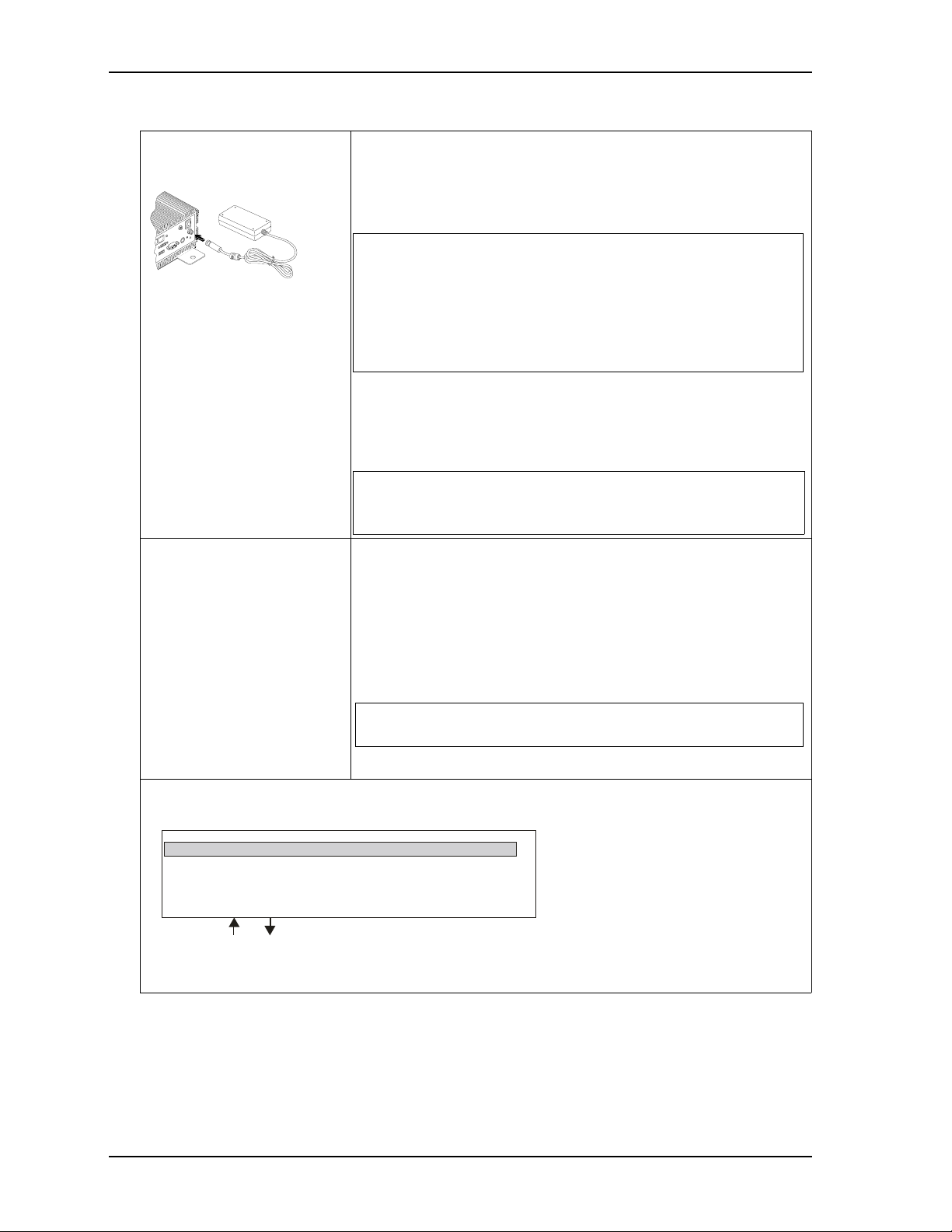
8) Follow these steps to apply
power to the RuffSystem.
IO
AUD
IN
C
D
ESET
R
ET 2
MS
HERN
KYBD/
1 ET
ET
SB 4
U
A
VG
3
SB
U
9) Verify the RuffSystem
satisfactorily powers on.
• Connect the AC Mating cable to the AC Adapter (options.) See
Figure 1 on page 5.
• Plug in the DC Cable Connector from the AC Adapter to the DC IN
jack on the RuffSystem. See Figure 3 on page 8.
NOTE Power supplied to the unit must be within the allowed range
depending on the model of the unit:
• +12VDC to +25VDC for RUFxxx models
• +14VDC to +32VDC for RUFxxxW models
Failure to provide proper power may damage the system
and void the warranty.
• Plug in the CRT monitor’s power cord to an AC outlet, and turn on
the monitor.
• Plug in the AC Mating Cable to an AC outlet.
• Press the RuffSystem Power Switch* to the On position.
NOTE *The Power Switch on the LittleBoard 800 RuffSystem is a
momentary switch. Press and momentarily hold this switch
(≈ 1 second) to power-on the RuffSystem.
• To enter the BIOS Setup, press the <Del> key during power-on self
test (POST).
Use BIOS Setup during the initial boot to set the desired options.
• You should see POST complete successfully before the system
starts loading the operating system (optional.) If you are using
Linux, the boot loader will appear first, similar to the one shown
below with the optional OS name displayed.
NOTE The optional 2 ½" hard disk drive comes with partitions for
the OS and swap space.
(The Linux 2.6 OS is shown as an example.)
GNU GRUB version 0.95 (632k lower/250768 upper memory)
Linux Kernel 2.6.x-xxx (recovery mode)
Use the and keys to s elect whic h entry is highlighted.
Press E nter to boot the sele cted OS, ‘e’ to edit the
commands before booting, ‘a’ to modify the kerne l
arguments before booting, or ‘c’ for a command-line.
Sys Linux_Boot_a
RdySy2U_2 4a
10 User’s Guide RuffSystem
Page 15

RuffSystem Setup
10) Using the
Optional Operating
System (OS)
• You should see a prompt on the monitor screen indicating the optional
OS is loading, or has loaded.
• Refer to the desired OS manual (not provided by ADLINK.)
• Refer to the optional LittleBoard 735, LittleBoard 800, or COM 840
Design Library and Support Software DVDs or QuickDrives
™ for
additional drivers and instructions.
RuffSystem User’s Guide 11
Page 16

RuffSystem Setup
12 User’s Guide RuffSystem
Page 17

Appendix A Technical Support
ADLINK Technology, Inc. provides a number of methods for contacting Technical Support listed in the
Tabl e A-1 below. Requests for support through the Ask an Expert web page are given the highest priority,
and usually are addressed within one working day.
• ADLINK Ask an Expert – This is a comprehensive support center designed to meet all your technical
needs. This service is free and available 24 hours a day through the Ampro By ADLINK web page at
tp://www.adlinktech.com/AAE/. This includes a searchable database of Frequently Asked Questions,
ht
which will help you with the common information requested by most customers. This is a good source
of information to look at first for your technical solutions. However, you must register online if you
wish to use the Ask a Question feature.
• Personal Assistance – You may also request personal assistance by creating an Ask an Expert account
and then going to the Ask a Question feature. Requests can be submitted 24 hours a day, 7 days a week.
You will receive immediate confirmation that your request has been entered. Once you have submitted
your request, you must log in to go to the My Stuff area where you can check status, update your
request, and access other features.
• InfoCenter – This service is also free and available 24 hours a day at the Ampro By ADLINK web page
at http://www.adlinktech.com
service.
The InfoCenter was created as a resource for embedded system developers to share ADLINK’s
knowledge, insight, and expertise. This page contains links to technical manuals, white papers,
specifications, and additional technical information.
. However, you must sign up online before you can login to access this
Table A-1. Technical Support Contact Information
Method Contact Information
Ask an Expert http://www.adlinktech.com/AAE/
Web Si t e http://www.adlinktech.com
Standard Mail ADLINK Technology, Incorporated
5215 Hellyer Avenue
San Jose, CA 95138-1007, USA
RuffSystem User’s Guide 13
Page 18

Appendix A Technical Support
14 User’s Guide RuffSystem
Page 19

Appendix B Physical Dimensions
5.51"
140 mm
C
L
C
L
C
L
C
L
12.20"
310 mm
10.00"
254 mm
3.90"
99 mm
(+/- 2 mm)
11.02"
280 mm
7,36"
187 mm
8.18"
208 mm
Figure B-1 shows the RuffSystem enclosure dimensions.
Figure B-1. Width, Depth, and Height Measurements
RuffSystem User’s Guide 15
Page 20

Appendix B Physical Dimensions
16 User’s Guide RuffSystem
 Loading...