

Page 1

PXIS-2690P
14-Slot 3U Integrated Portable PXI Chassis
with 500 W AC Power Supply
User’s Manual
Manual Rev. 2.00
Revision Date: December 06, 2006
Part No: 50-17025-1000
Advance Technologies; Automate the World.
Page 2

Copyright 2006 ADLINK TECHNOLOGY INC.
All Rights Reserved.
Disclaimer
The information in this document is subject to change without prior
notice in order to improve reliability, design, and function and does
not represent a commitment on the part of the manufacturer.
In no event will the manufacturer be liable for direct, indirect, special, incidental, or consequential damages arising out of the use or
inability to use the product or documentation, even if advised of
the possibility of such damages.
This document contains proprietary information protected by copyright. All rights are reserved. No part of this manual may be reproduced by any mechanical, elec tronic, or other means in a ny form
without prior written permission of the manufacturer.
Trademark Information
PXI is registered trademarks of PXI Systems Alliance. Other product names mentioned herein are used for identification purposes
only and may be trademarks and/or registered trademarks of their
respective companies.
Page 3
Getting service from ADLINK
Customer satisfaction is our top priority. Contact us should you
require any service or assistance.
ADLINK TECHNOLOGY INC.
Web Site: http://www.adlinktech.com
Sales & Service: Service@adlinktech.com
TEL: +886-2-82265877
FAX: +886-2-82265717
Address: 9F, No. 166, Jian Yi Road, Chungho City,
Taipei, 235 Taiwan
E-mail or fax this completed service form for prompt and satisfactory service.
Company Information
Company/Organization
Contact Person
E-mail Address
Address
Country
TEL FAX:
Web Site
Product Information
Product Model
OS:
Environment
M/B: CPU:
Chipset: BIOS:
Please give a detailed description of the problem(s):
Page 4

Page 5

Table of Contents
List of Tables.......................................................................... iii
List of Figures........................................................................ iv
1 Introduction ........................................................................ 1
1.1 Features............................................................................... 2
1.2 Unpacking Checklist ........................................ .... ... ... ... .... ... 2
2 Chassis Overview............................................................... 3
2.1 Front View (closed).............................................................. 3
2.2 Front-Right View..................................... ... ... ... .... ... ............. 4
2.3 Front-Left View ................... .... ... ... ... .... ... ... ... ... .... ................ 5
2.4 Dimensions and Rear View ................................................. 6
2.5 Backplane overview............................................................. 7
Backplane functions ................................ ... .....................8
System Controller Slot ....................................................8
Star Trigger Slot .............................................................. 8
Peripheral Slots .............................................................. 9
Local Bus ........................................................................9
Trigger Bus .....................................................................9
System Reference Clock .............................................. 10
3 Installation ........................................................................ 11
3.1 Removing the Module Cover............................................. 12
3.2 Installing the System Controller......................................... 13
3.3 Installing Peripheral Modules............................................. 15
3.4 Replacing the Module Cover ............................................. 17
3.5 Using the Keyboard and Touchpad ................................... 18
3.6 Removing and Replacing the Keyboard Tray.................... 20
3.7 Powering up the System.................................................... 23
3.8 Using the Touch Panel Feature......................................... 25
3.9 Turning Off the LCD........................................................... 25
3.10 Monitoring the System....................................................... 26
4 Troubleshooting and Maintenance................................. 27
4.1 Installation Problems ......................................................... 27
4.2 BIOS Beeps......................................... ... ... ... ... .... ... ........... 27
4.3 Basic Troubleshooting....................................................... 28
Table of Contents i
Page 6

4.4 Maintenance ...................................................................... 30
Handling the chassis .....................................................30
Taking care of the keyboard/touchpad ......................... 30
Cleaning the LCD .........................................................30
Handling cables ............................................................30
Power requirements ......................................................31
A Specifications.................................................................... 33
A.1 General.............................................................................. 33
A.2 Power Supply........................... .... ...................................... 33
A.3 Integrated Display, Input Devices, and Cooling................. 33
A.4 Physical.............................................................................. 34
A.5 Operating Environment...................................................... 34
A.6 Backplane.......................................................................... 34
A.7 Safety and EMC/EMI Compliance ..................................... 35
A.8 Reliability and Serviceability .............................................. 35
B Backplane Drawing and Pin Assignments..................... 37
B.1 Backplane Layout .............................................................. 37
B.2 Backplane cBX-3014L Connectors
Pin Assignments................ ... ... ... .... ... ... ... ................ 38
PXI Connectors Pin Assignments .................................38
B.3 Bus Segments and Interrupt Routings............................... 44
B.4 Bus Segments and Interrupt Routings............................... 45
Important Safety Instructions............................................... 47
Warranty Policy ..................................................................... 49
ii Table of Contents
Page 7

List of Tables
Table 2-1: Reference Clock Jumper Setting ............................ 10
Table 3-1: LED Indications ...................................................... 26
List of Tables iii
Page 8

List of Figures
Figure 2-1: PXIS-2690P Front View.............................. .... ... ... ... .. 3
Figure 2-2: PXIS-2690P Front-Right View ................................... 4
Figure 2-3: PXIS-2690P Front-Left View...................................... 5
Figure 2-4: PXIS-2690P Dimensions ........................................... 6
Figure 2-5: PXIS-2690P Rear View ............................................. 6
Figure 2-6: cBX-3014L Front View............................................... 7
Figure 2-7: cBX-3014L Rear View ............................................... 7
Figure 2-8: Backplane Functions ................................................. 8
Figure B-1: cBX-3014L Front View............................................. 37
Figure B-2: cBX-3014L Rear View ............................................. 37
iv List of Figures
Page 9
1 Introduction
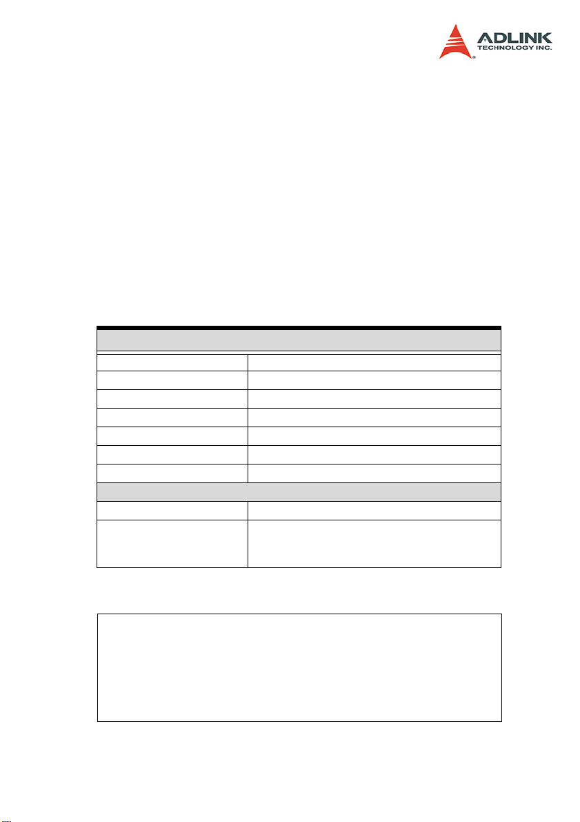
The ADLINK PXIS-2690P is world's first highly integrated, 14-slot
portable PXI chassis designed for advanced PXI instrumentation
applications. The PXIS-2690P comes with a system slot and 13
peripheral slots that conveniently accommodate multiple PXI modules. The PXI chassis incorporates a high-brightness 15" TFT
LCD display with touch panel, keyboard/touchpad, and a slim DVD
combo drive into a single frame to provide superior portability and
maximum performance.
Constructed in high-quality aluminum alloy, the PXIS-2690P delivers a fortified and compact chassis, minus the weight. An industrial-grade 500 W AC power supply comes pre-installed to the
chassis and offers reliable and stable power to system components and peripheral modules. With three 120 mm x 120 mm system fans, the PXIS-2690P guarantees superb air flow to maintain
a cool and efficient operating temperature. The ADLINK PXIS2690P is an ideal solution for advanced PXI applications requiring
portability, robustness, and easy-deployment.
Introduction 1
Page 10

1.1 Features
X Ruggedly-designed for portable instrumentation applica-
tions
X Supports both 3U PXI and CompactPCI modules
X PXI Specifications Rev. 2.2-compliant
X Equipped with a system slot and 13 PXI/CompactPCI
peripheral slots
X 15" high-brightness TFT LCD display with up to 1024x768
resolution
X Multiple input devices, including keyboard, touch pad, and
touch panel
X Built-in slim-type DVD combo drive
X 500 W industrial-grade ATX power supply
X Top cover for protecting PXI modules and wiring
1.2 Unpacking Checklist
Before unpacking, check the shipping carton for any damage. If
the shipping carton and/or contents are damaged, inform your
dealer immediately. Retain the shipping carton and packing materials for inspection. Obtain authorization from your dealer before
returning any product to ADLINK.
Check if the following items are included in the package.
X PXIS-2690P Chassis, 3U 14-Slot Portable PXI Chassis with
Integrated LCD
X Carrier bag
X User's Manual
X All-in-One CD
NOTE OEM version package may vary depending on customer
requests. The assigned controller and/or peripheral modules may be pre-installed and shipped with the chassis.
Inquire with your dealer for additional information on
these options.
2Introduction
Page 11
2 Chassis Overview
This section describes the PXIS-2690P chassis including the location of basic components and control, mechanical dimensions,
and the backplane functions and features.
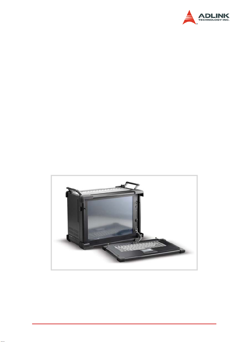
2.1 Front View (closed)
Slots cover
Handle
Keyboard/touchpad tray
Figure 2-1: PXIS-2690P Front View
Handle
Chassis Overview 3
Page 12
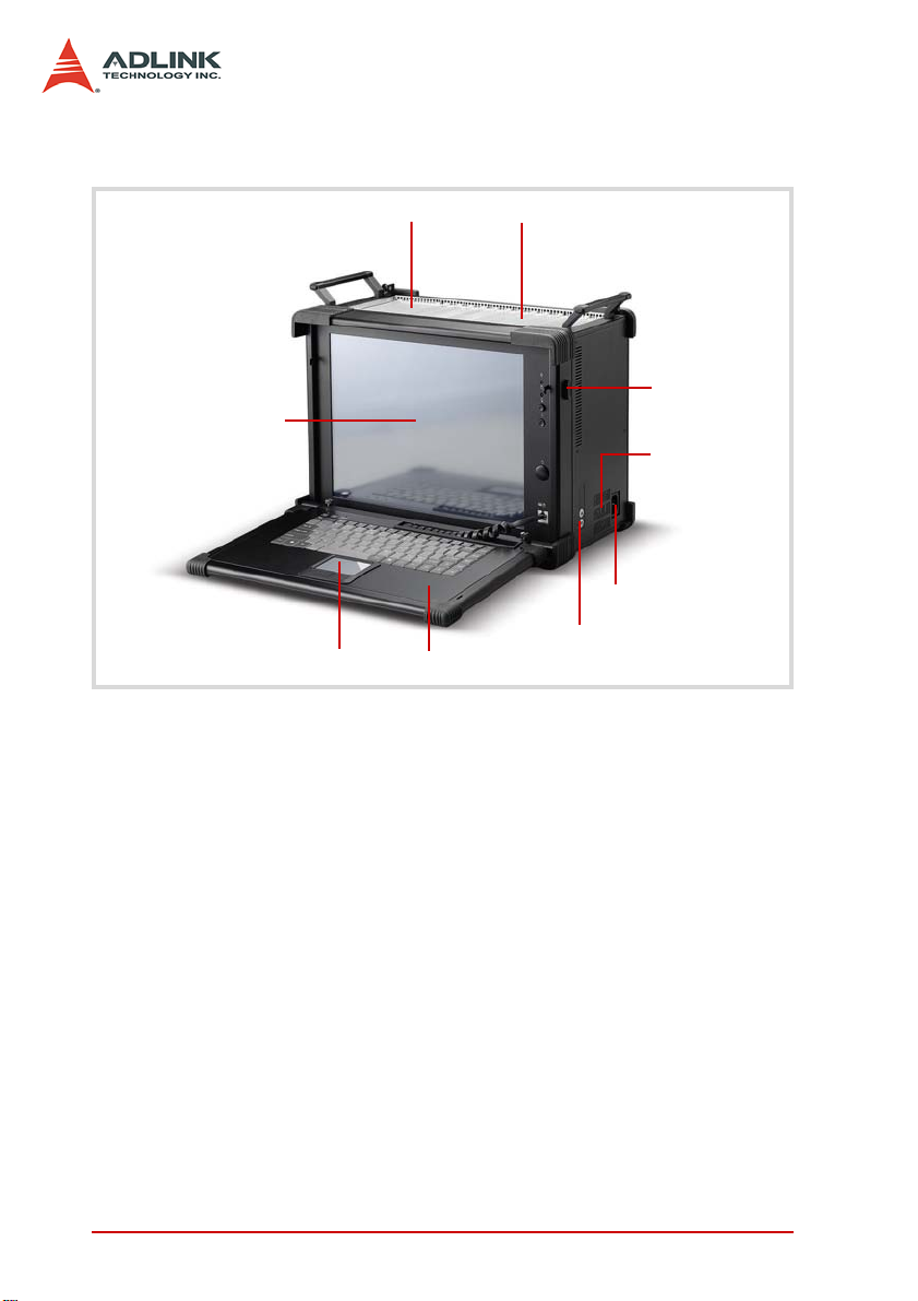
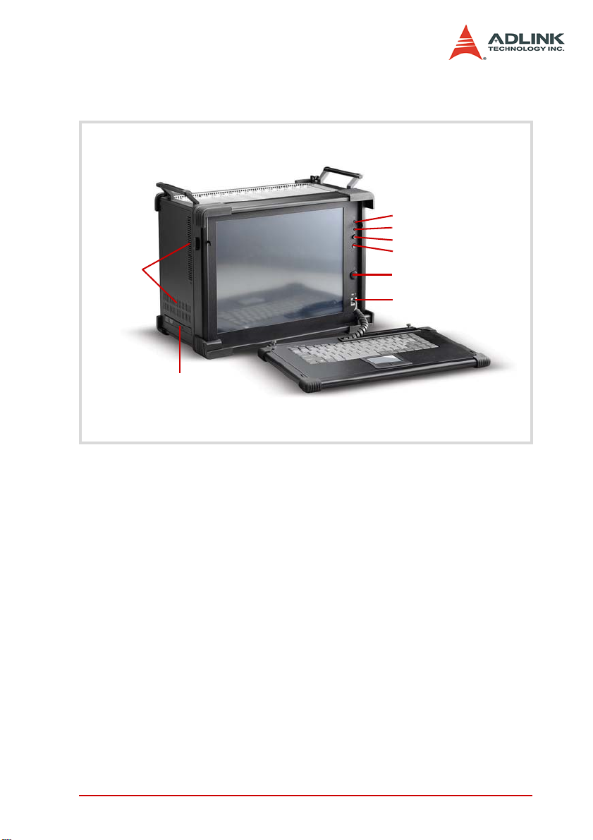
2.2 Front-Right View
Peripheral slots
15” LCD
Touchpad
System slot
Keyboard tray
Figure 2-2: PXIS-2690P Front-Right View
Keyboard tray
latch
Power supply
ventilation holes
Power connector
LCD brightness
control buttons
4 Chassis Overview
Page 13
2.3 Front-Left View
System
ventilation
DVD-ROM
Figure 2-3: PXIS-2690P Front-Left View
Power LED
HDD LED
LCD switch
Reset button
Power button
Keyboard/touchpad port
Chassis Overview 5
Page 14
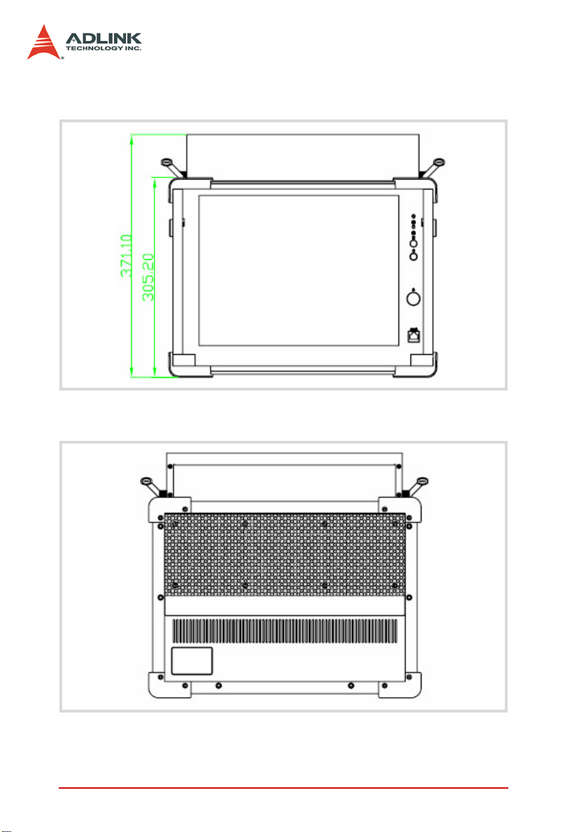
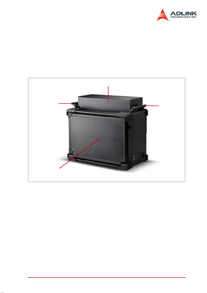
2.4 Dimensions and Rear View
Figure 2-4: PXIS-2690P Dimensions
Figure 2-5: PXIS-2690P Rear View
6 Chassis Overview
Page 15
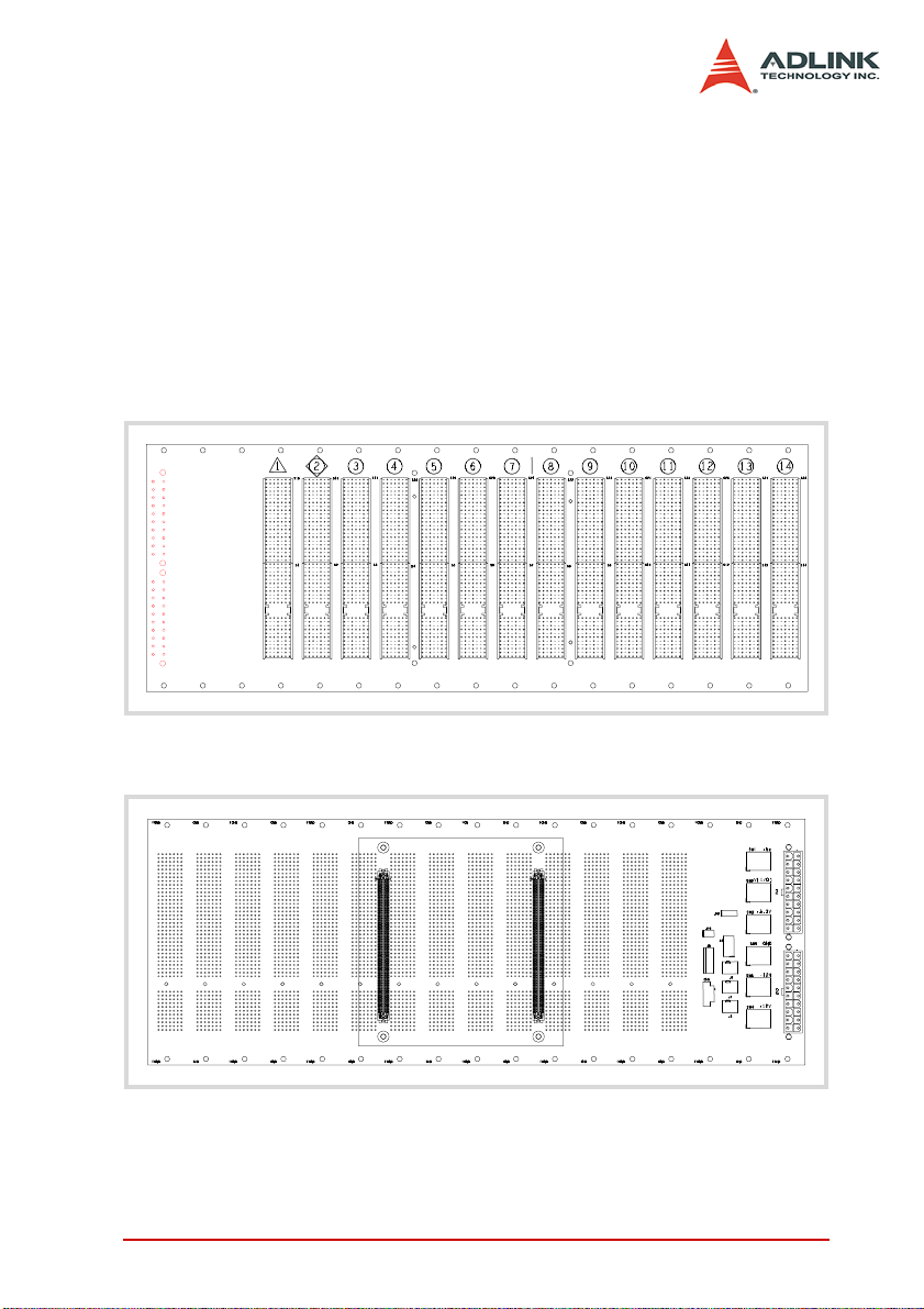
2.5 Backplane overview
The cBX-3014L backplane supports both PXI modules and standard CompactPCI cards. The backplane’s P1 connector signals
comply with the requirements of CompactPCI specifications for
both peripheral and system modules.
PXI-specific signals are located on P2. Only those signals
reserved or not used for the CompactPCI 64-bit specification ar e
found on PXI specific signals, allowing all modules that comply
with the former to function in the chassis.
Figure 2-6: cBX-3014L Front View
Figure 2-7: cBX-3014L Rear View
Chassis Overview 7
Page 16
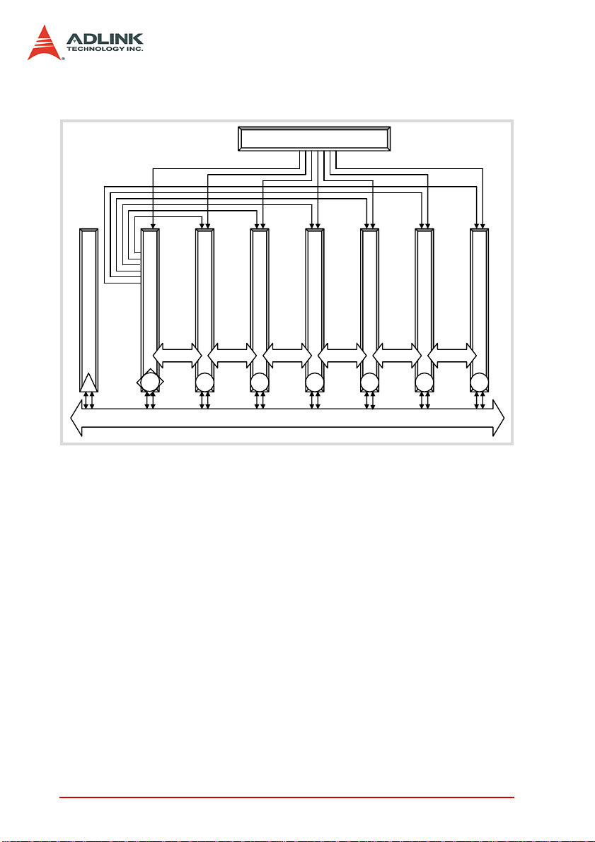
Backplane functions
p
p
p
p
p
p
PXI Star Triggers
Clock 10 MHz Buffer Circuitry
heral slot
System Controller
1
Star Trigger Controller
2
Peri
3
PXI Trigger Bus Segment and PCI Bus Segment
heral slot
Peri
4
heral slot
Peri
Local BusLocal BusLocal BusLocal Bus
5
heral slot
Peri
Local Bus Local Bus
6
heral slot
Peri
…
14
Figure 2-8: Backplane Functions
System Controller Slot
The PXIS-2690P system controller slot is at Slot 1 as defined by
PXI specifications. It has three controller expansion slots (total
four), which are used for system controller modules that are wider
than one slot. As defined in the PXI specification, these slots allow
the controller to expand towards the left to prevent the controller
from using up peripheral slots.
Star Trigger Slot
Slot 2 is reserved for the star trigger. Th is slot has dedicated trigger lines to slots 3 to 14. The start trigger slot provides individual
triggers to peripherals and is designed for modules with ST functionalities.
heral slot
Peri
8 Chassis Overview
Page 17

Peripheral Slots
Thirteen slots are available for installation of peripheral modules.
This includes the star trigger controller slot.
Local Bus
The cBX-3014L local bus is a daisy-chained bus that connects
each peripheral slot with its adjacent (left and right) slot. A local
bus is 13 lines wide, transmits analog or digital signals between
modules, and/or provides a high-speed sideband communication
path without affecting the PXI bus bandwidth.
Per PXI specifications, the local bus connects all slots except slots
1 (system slot) and 2.
Trigger Bus
The PXIS-2690P incorporates a PXI trigger bus to synchronize the
operation of several and different PXI peripheral modules, or to
use one module to control the timed sequences of operations performed on other modules. Modu les can exchange trig gers via the
trigger bus, allowing precise timed responses to asynchronous
external events that the system monito rs or con tro ls.
Chassis Overview 9
Page 18
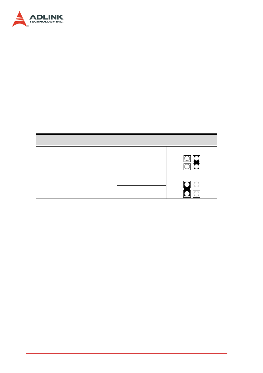
System Reference Clock
The PXIS-2690P supplies a 10 MHz system reference clock signal
(PXI_CLK10) to every peripheral slot independently. An independent buffer (having a source impedance matched to the b ackplan e
and a skew of less than 1 ns between slots) drives the clock signal
to each peripheral slot. You can use this common reference clock
signal to synchronize multiple mod ules in a measurem ent or control system, or drive PXI_CLK10 from an external source through
the PXI_CLK10_IN pin on the P2 connector of the star trigger slot.
You can select the internal or external clock by setting jumpers
JP2 and JP3 in the backplane rear. Refer to the jumper settings
below.
Description Jumper Settings
External clock (PXI_CLK10_IN
on star trigger slot)
Internal clock (10 MHz system
clock PXI_CLK10)
Table 2-1: Reference Clock Jumper Setting
JP2 Open
JP3 Short
JP2 Short
JP3 Open
10 Chassis Overview
Page 19

3 Installation
The chapter tells you how to install the system controller, peripheral modules, and drivers to the PXIS-2690P chassis. It also provides information on how to remove the keyboard tray, power up,
and monitor the system.
Installation 11
Page 20

3.1 Removing the Module Cover
The PXIS-2690P comes with a module cover that protects wirings
and connections to the system controller and peripheral modules.
You must remove the module cover before installing the system
controller and/or peripheral modules.
To remove the module cover:
1. Locate two screws on both sides of the cover, then
loosen them until the cover disengages from the chassis.
2. Pull the rear edge of the cove r up to a 45º angle, then lift.
3. Set the module cover aside.
12 Installation
Page 21

3.2 Installing the System Controller
The PXIS-2690P comes with a system controller slot that supports
a PXI or cPCI-based system controller. We recommend the following system controllers for use with PXIS-2690P:
X PXI-3800
X PXI-3800/CM13
X PXI-3800/PM18
X PXI-3800/PM18+
To install the system controller:
1. Make sure that the CPU, memory module(s), and stor-
age device(s) are properly installed on the system controller module.
2. Locate the system controller slot (Slot 1, widest slot
cover) and controller expansion slot (first slot from the
left).
3. Depending on the system cont roller’s slot space require-
ment, remove the system controller slot cover (Slot 1),
then the controller expansion slot.
4. Push down (loose) the system controller module’s ejec-
tor/injector handle(s).
Installation 13
Page 22

5. Align the module’s top and bottom edges to the card
guides, then carefully slide the module into the chassis,
6. Push the ejecto r/injector handle( s) up to secure the module in place, then fasten the screws on the module front
panel.
7. Connect all devices to the system controller, then
replace the module cover following the instructions in
section 3.4.
14 Installation
Page 23

3.3 Installing Peripheral Modules
The PXIS-2690P supports up to thirteen PXI/cPCI peripheral modules, including a star trigger module.
To install a peripheral module:
1. Select an available slot, then remove the slot cover.
2. Push down (loose) the peripheral module’s ejector/injec-
tor handle(s), then align the module’s top and bottom
edges to the card guides.
3. Carefully slide the module into the chassis.
Installation 15
Page 24

4. Pull the ejector/injector handle(s) down to connect the
module firmly to the chassis backplane,
5. Push the ejecto r/injector handle( s) up to secure the module, then fasten the screws on the module front panel.
6. Connect all devices to the module, then replace the
module cover following the instructions in section 3.4.
16 Installation
Page 25

3.4 Replacing the Module Cover
After installing the system controller and peripheral modules, and
connecting all necessary devices, replace the module cover to
protect module connections/wirings.
To replace the module cover:
1. Insert the module cover tabs to the holes on top of the
chassis.
2. Push down the rear edge of the module cover until its
screw holes align with the lock screws.
Lock screw
3. Secure the module cover with the lock screws.
Installation 17
Page 26

3.5 Using the Keyboard and Touchpad
The PXIS-2690P comes with an integrated 87-key keyboard and
touchpad for data input. The keyboard is Windows®-compliant
while the touchpad functions as a mouse when moving the cursor
in a graphical user interface (GUI). The buttons below the touchpad corresponds to the left and right mouse buttons. Tapping the
touchpad corresponds to a left-button click.
NOTE Opening the keyboard tray also shows the LCD and front
To use the keyboard and touchpad:
1. Locate two keyboard tray latches on both sides of the
2. With both thumbs re straining the keyboard tr ay, push th e
panel control buttons and LEDs.
chassis.
latches up to release.
18 Installation
Page 27

3. Place the keyboard tray down, then insert the keyboard/
touchpad connector to the keyboard/touchpad port.
Installation 19
Page 28

3.6 Removing and Replacing the Keyboard Tray
For applications that do not require a keyboard and touchpad, you
may remove the keyboard tray.
To remove the keyboard tray:
1. Disconnect the keyboard/touchpad connector from the
keyboard/touchpad port.
2. Locate two keyboard tray lo ck screws, then loosen them.
.
20 Installation
Page 29

3. With two hands supporting the tray, push the lock
screws inward until the tray disengages from the chassis.
4. Set the keyboard tray aside.
Installation 21
Page 30

To replace the keyboard tray:
1. Push the keyboard tray lock screws inward until the
metal rods retract..
2. Align the metal rods with the lock holes, then release the
lock screws until the metal rods click in place..
3. Fasten the lock screws to secure the tray.
4. Connect the keyboard/touchpad connector to the keyboard/touchpad port.
22 Installation
Page 31

3.7 Powering up the System
The PXIS-2690P is equipped with a universal power supply unit
that does not require input voltage selection.
To turn on the system:
1. Connect one end of the supplied power cable to the
power connector located at the right side of the chassis..
2. Plug the other end of the AC power cord to a properly
grounded wall socket or power strip. When power is
available, the chassis goes to standby power mode
(OFF).
3. Press the power button from the front panel to turn the
system on. The power LED in the front p anel lights up
green and the chassis fans start to operate.
Installation 23
Page 32

To turn off the system:
1. Shut down the syste m via the operating system.
2. Press the power button to put the system in standby
(OFF) mode. The power button pr otru des fr om the beze l
when the system is in standby power mode.
NOTE If the chassis fails to turn on, refer to Chapter 4: Trouble-
shooting and Maintenance for details.
24 Installation
Page 33

3.8 Using the Touch Panel Feature
The PXIS-2690P LCD is equipped with touch panel functionality
for convenient data input and GUI navigation. To enjoy the touch
panel function, you must install the touch panel driv er .
To install the touch panel driver:
1. Place the ADLINK T&M All-in-One CD in the DVD-ROM
located on the left side of the chassis.
2. Explore the contents of the CD and locate the touch
panel drivers from the following path:
X:\Driver Installation\PXI Platform\PXI chassis\
PXIS-2690P\Touch_Panel\Driver
NOTE If the touch panel feature fails, refer to Chapter 4: Trou-
bleshooting and Maintenance for details.
3.9 Turning Off the LCD
When not in use, you may turn off the LCD by pressing the LCD
sleep button located in the chassis front panel.
Installation 25
Page 34

3.10 Monitoring the System
Light Emitting Diodes (LEDs) on the front panel tell you the power
status and hard disk drive data read/write activity. Refer to
Table 3-1 for details.
LED Function Color Status Indication
ON The system is on
Power Power indication Green
HDD
Data read/write
activity
Table 3-1: LED Indications
Red
OFF
OFF
Flashing
The system is off or in
standby power mode
The system is off, on
standby power, or has
no HDD activity
Data is read/written
from/to the HDD
26 Installation
Page 35

4 Troubleshooting and Maintenance
4.1 Installation Problems
Failure to start the system usu ally results from incorrect installation of the system controller, peripheral modules, etc. Go through
the following checklist before you start up the system.
X The system controller is properly installed and secured.
X All peripheral modules are properly seated on the slots.
X All cables are properly connected to the system controller/
peripheral modules.
X All peripheral modules installed are compatible for use in
the chassis.
X The power cord is properly plugged into the chassis power
connector and power outlet/wall socket/power strip.
If the system fails to turn on even after all installation conditions
are met, remove all peripheral modules that you installed, then try
again. If the system turns on properly, try installing one peripheral
module at a time, then test if the system will power-up. You may
also try installing the modules into different slots until you get the
desired result.
4.2 BIOS Beeps
BIOS beeps indicate errors in system initialization. These beeps
are usually associated with video and memory errors. If the system beeps during start up, check if the display is properly connected to the system controller or if the integrated LCD drivers are
properly installed. You may also check if the memory modules are
properly installed in the system controller.
Troubleshooting and Maintenance 27
Page 36

4.3 Basic Troubleshooting
Problem What to Do
System fails to power
up
There is no LCD display
There is no video
output in the external
display
The keyboard doesn’t
work
X Check if the power cord is properly
plugged into the chassis power connector and wall socket/power strip.
X Check if the wall socket/power strip
is live.
X Press the power button at the chas-
sis front panel.
X Make sure the system is turned on.
X Connect an external display to the
system controller’s VGA port, then
check if there is video output.
X If video output is present on the
external display, adjust your display
settings and enable LCD video.
X If video output is not present on the
external display, check if the system
controller is properly installed.
X If there is no video output even when
the system controller is properly
installed, contact ADLINK for further
assistance.
X Redirect the video output to the inte-
grated LCD.
X Check if your external display is
functional.
X Check your display settings and
make sure you enable external
video.
X Check if the keyboard plug is prop-
erly inserted to the keyboard port.
X Disconnect an external PS/2 or USB
keyboard cable from the system
controller, if any.
28 Troubleshooting and Maintenance
Page 37

Problem What to Do
The touchpad doesn’t
work
The DVD-ROM cannot
read a disc
X Disconnect an external PS/2 or
USB mouse cable from the system
controller, if any.
X Install the mouse/touchpad drivers
if the operating system requires
manual installation.
X Make sure you place only compati-
ble discs to the DVD-ROM.
X Make sure the system detects the
DVD-ROM drive during POST. If it
fails to detect the drive, call
ADLINK for further assistance.
Troubleshooting and Maintenance 29
Page 38

4.4 Maintenance
Handling the chassis
Make sure that the keyboard tray is closed before transporting/
moving the chassis. The keyboard tray serves as the LCD protection. It is recommended that you transport the chassis in the carr ying case provided, or carry it using the handles. The handles are
designed to carry the weight of the chassis for superior portability
and balance.
Taking care of the keyboard/touchpad
The integrated keyboard allows you to input data faster in any
application. It also protects the LCD when transporting the system.
Avoid dropping liquids or small objects on the keyboard. You may
use a compress air cleaner to remove dusts and dirt that build up
under the keys.
Keep the touch pad surface dry and clean for better performance.
Cleaning the LCD
Clean the LCD periodically with a moist cloth for better display.
Observe the following precautions when cleaning the LCD.
X Do not use any abrasive material to wipe the LCD screen to
avoid scratching the LCD surface.
X Do not apply too much pressure on the surfa ce when wiping
the LCD screen.
X Do not use a cleaner that contains alcohol.
X Do not use a rough cloth that could scratch the LCD screen
surface.
X Clean the LCD screen with gentle wipes in one direction.
Handling cables
Treat all cables with care. Do not over extend any cable to prevent
internal breaking. All cables and plugs must be handled or connected properly.
30 Troubleshooting and Maintenance
Page 39

Power requirements
Make sure that the power cord is in good condition b efore plugging
it into the system. You also need to check the reliability of the
power source. The PXIS-2690P power supply is capable of handling 100 V to 240 V AC within the 50 Hz to 60 Hz range. Do not
connect the PXIS-2690P on an already overloaded circuit.
Troubleshooting and Maintenance 31
Page 40

32 Troubleshooting and Maintenance
Page 41

A Specifications
A.1 General
Complies with PICMG 2.2 specifications.
A.2 Power Supply
X AC input: 100 to 240 VAC, 47 to 63 Hz
X DC output: 500W
VDC Minimum Maximum
+5 V 3.0 A 50.0 A
+3.3 V 0.3 A 28.0 A
+12 V 2.0 A 35.0 A
-12 V 0.1 A 0.8 A
NOTE Total combined power from +5 V and +3.3 V should not
exceed 250 W.
A.3 Integrated Display, Input Devices, and Cooling
Display: 15" TFT LCD, up to 1024 x 768 resolution
Input Devices:
X 87-keys keyboard with touchpad
X Built-in 15" touch screen
Drive Bay: Slim-type DVD-ROM drive
Cooling: Three 120mm x 120mm ball-bearing fans; 53.2 CFM
each
Specifications 33
Page 42

A.4 Physical
Dimension: 400 mm x 291 mm x 223.3 mm (WxHxD, no fan
frame)
Weight: 12.5 kg
A.5 Operating Environment
Operating environment
X Ambient temperature: 0°C to 50°C
X Relative humidity: 10% to 90%, non-condensing
Storage environment
X Ambient temperature: -20°C to 70°C
X Relative humidity: 5% to 95%, non-condensing
Shock: 10 G
peak-to-peak
, 11ms duration
Random Vibration
X Operating: 5 Hz to 500 Hz, 0.31 GRMS each axis
X Non-operating: 5 Hz to 500 Hz, 2.46 GRMS each axis
A.6 Backplane
Backplane bare-board material: UL 94V-0 ra te d
Peripheral slots with star signals: from third to 14th slot
PXI trigger bus: all
PXI local bus: all
Slots:
X One system slot on the left-hand side
X 13 peripheral slots supporting both PXI and CompactPCI
modules
34 Specifications
Page 43

A.7 Safety and EMC/EMI Compliance
EMC/EMI: CE, FCC Class A
A.8 Reliability and Serviceability
MTBF:
X Backplane: 800,000 hrs
X Power Supply: 100,000 hrs @ full load
Specifications 35
Page 44

36 Specifications
Page 45

B Backplane Drawing and Pin
Assignments
B.1 Backplane Layout
The following figures show the front and rear view of the
PXIS-2690P backplane.
.
Figure B-1: cBX-3014L Front View
Figure B-2: cBX-3014L Rear View
Backplane Drawing and Pin Assignments 37
Page 46

B.2 Backplane cBX-3014L Connectors
Pin Assignments
PXI Connectors Pin Assignments
System Slot (Slot #1) P1 Pin Assignment
Pin Z A B C D E F
25 GND +5V REQ64# ENUM# +3.3V +5V GND
24 GND AD[1] +5V V(I/O) AD[0] ACK64# GND
23 GND +3.3V AD[4] AD[3] +5V AD[2] GND
22 GND AD[7] GND +3.3V AD[6] AD[5] GND
21 GND +3.3V AD[9] AD[8] GND C/BE[0]# GND
20 GND AD[12] GND V(I/O) AD[11] AD[10] GND
19 GND +3.3V AD[15] AD[14] GND AD[13] GND
18 GND SERR# GND +3.3V PAR C/BE[1]# GND
17 GND +3.3V IPMB_SCL IPMB_SDA GND PERR# GND
16 GND DEVSEL# GND V(I/O) STOP# LOCK# GND
15 GND +3.3V FRAME# IRDY# GND TRDY# GND
12-14 Key
11 GND AD[18] AD[17] AD[16] GND C/BE[2]# GND
10 GND AD[21] GND +3.3V AD[20] AD[19] GND
9 GND C/BE[3]# GND AD[23] GND AD[22] GND
8 GND AD[26] GND V(I/O) AD[25] AD[24] GND
7 GND AD[30] AD[29] AD[28] GND AD[27] GND
6 GND REQ# (1) GND +3.3V CLK (1) AD[31] GND
5 GND BRSVP1A5 BRSVP1B5 PCIRST# GND GNT# (1) GND
4 GND IPMB_PWR GND V(I/O) INTP INTS GND
3 GND INTA# (1) INTB# (1) INTC# (1) +5V INTD# (1) GND
2 GND TCK +5V TMS TDO TDI GND
1 GND +5V -12V TRST# +12V +5V GND
Pin Z A B C D E F
38 Backplane Drawing and Pin Assignments
Page 47

System Slot (Slot #1) P2 Pin Assignment
Pin Z A B C D E F
22 GND PXI_BRSVA22 PXI_BRSVB22 PXI_BRSVC22 PXI_BRSVD22 PXI_BRSVE22 GND
21 GND CLK6 GND NC NC NC GND
20 GND CLK5 GND NC GND NC GND
19 GND GND GND SMBDATA SMBCLK SMBALERT- GND
18 GND PXI_TRIG3 PXI_TRIG4 PXI_TRIG5 GND PXI_TRIG6 GND
17 GND PXI_TRIG2 GND PRST# REQ6# GNT6# GND
16 GND PXI_TRIG1 PXI_TRIG0 DEG# GND PXI_TRIG7 GND
15 GND PXI_BRSVA15 GND FAL# REQ5# GNT5# GND
14 GND AD[35] AD[34] AD[33] GND AD[32] GND
13 GND AD[38] GND V(I/O) AD[37] AD[36] GND
12 GND AD[42] AD[41] AD[40] GND AD[39] GND
11 GND AD[45] GND V(I/O) AD[44] AD[43] GND
10 GND AD[49] AD[48] AD[47] GND AD[46] GND
9 GND AD[52] GND V(I/O) AD[51] AD[50] GND
8 GND AD[56] AD[55] AD[54] GND AD[53] GND
7 GND AD[59] GND V(I/O) AD[58] AD[57] GND
6 GND AD[63] AD[62] AD[61] GND AD[60] GND
5 GND C/BE[5]# GND V(I/O) C/BE[4]# PAR64 GND
4 GND V(I/O) PXI_BRSVB4 C/BE[7]# GND C/BE[6]# GND
3 GND CLK4 GND GNT3# REQ4# GNT4# GND
2 GND CLK2 CLK3 GND (SYS#) GNT2# REQ3# GND
1 GND CLK1 GND REQ1# GNT1# REQ2# GND
Pin Z A B C D E F
Backplane Drawing and Pin Assignments 39
Page 48

Star Trigger Slot (Slot #2) P1 Pin Assignment
Pin Z A B C D E F
25 GND +5V REQ64# ENUM# +3.3V +5V GND
24 GND AD[1] +5V V(I/O) AD[0] ACK64# GND
23 GND +3.3V AD[4] AD[3] +5V AD[2] GND
22 GND AD[7] GND +3.3V AD[6] AD[5] GND
21 GND +3.3V AD[9] AD[8] M66EN C/BE[0]# GND
20 GND AD[12] GND V(I/O) AD[11] AD[10] GND
19 GND +3.3V AD[15] AD[14] GND AD[13] GND
18 GND SERR# GND +3.3V PAR C/BE[1]# GND
17 GND +3.3V IPMB_SCL IPMB_SDA GND PERR# GND
16 GND DEVSEL# GND V(I/O) STOP# LOCK# GND
15 GND +3.3V FRAME# IRDY# GND TRDY# GND
12-14 Key
11 GND AD[18] AD[17] AD[16] GND C/BE[2]# GND
10 GND AD[21] GND +3.3V AD[20] AD[19] GND
9 GND C/BE[3]# IDSEL (1) AD[23] GND AD[22] GND
8 GND AD[26] GND V(I/O) AD[25] AD[24] GND
7 GND AD[30] AD[29] AD[28] GND AD[27] GND
6 GND REQ# (1) GND +3.3V CLK (1) AD[31] GND
5 GND BRSVP1A5 BRSVP1B5 PCIRST# GND GNT# (1) GND
4 GND IPMB_PWR GND V(I/O) INTP INTS GND
3 GND INTA# (1) INTB# (1) INTC# (1) +5V INTD# (1) GND
2 GND TCK +5V TMS TDO TDI GND
1 GND +5V -12V TRST# +12V +5V GND
Pin Z A B C D E F
40 Backplane Drawing and Pin Assignments
Page 49

Star Trigger Slot (Slot #2) P2 Pin Assignment
Pin Z A B C D E F
22 GND PXI_BRSVA22 PXI_BRSVB22 PXI_BRSVC22 PXI_BRSVD22 PXI_BRSVE22 GND
21 GND PXI_LBR0 GND PXI_LBR1 PXI_LBR2 PXI_LBR3 GND
20 GND PXI_LBR4 PXI_LBR5 PXI_STAR0 (2) GND PXI_STAR1 (2) GND
19 GND PXI_STAR2 (2) GND PXI_STAR3 (2) PXI_STAR4 PXI_STAR5 GND
18 GND PXI_TRIG3 PXI_TRIG4 PXI_TRIG5 GND PXI_TRIG6 GND
17 GND PXI_TRIG2 GND N/C PXI_CLK10_IN PXI_CLK10 GND
16 GND PXI_TRIG1 PXI_TRIG0 N/C GND PXI_TRIG7 GND
15 GND PXI_BRSVA15 GND N/C PXI_STAR6 PXI_LBR6 GND
14 GND AD[35] AD[34] AD[33] GND AD[32] GND
13 GND AD[38] GND V(I/O) AD[37] AD[36] GND
12 GND AD[42] AD[41] AD[40] GND AD[39] GND
11 GND AD[45] GND V(I/O) AD[44] AD[43] GND
10 GND AD[49] AD[48] AD[47] GND AD[46] GND
9 GND AD[52] GND V(I/O) AD[51] AD[50] GND
8 GND AD[56] AD[55] AD[54] GND AD[53] GND
7 GND AD[59] GND V(I/O) AD[58] AD[57] GND
6 GND AD[63] AD[62] AD[61] GND AD[60] GND
5 GND C/BE[5]# GND V(I/O) C/BE[4]# PAR64 GND
4 GND V(I/O) PXI_BRSVB4 C/BE[7]# GND C/BE[6]# GND
3 GND PXI_LBR7 GND PXI_LBR8 PXI_LBR9 PXI_LBR10 GND
2 GND PXI_LBR11 PXI_LBR12 N.C (SYS#) PXI_STAR7 PXI_STAR8 GND
1 GND PXI_STAR9 GND PXI_STAR10 PXI_STAR11 PXI_STAR12 GND
Pin Z A B C D E F
Backplane Drawing and Pin Assignments 41
Page 50

General Peripheral Slot (Slot #3~#14) P1 Pin Assignment
Pin Z A B C D E F
25 GND +5V REQ64# ENUM# +3.3V +5V GND
24 GND AD[1] +5V V(I/O) AD[0] ACK64# GND
23 GND +3.3V AD[4] AD[3] +5V AD[2] GND
22 GND AD[7] GND +3.3V AD[6] AD[5] GND
21 GND +3.3V AD[9] AD[8] M66EN C/BE[0]# GND
20 GND AD[12] GND V(I/O) AD[11] AD[10] GND
19 GND +3.3V AD[15] AD[14] GND AD[13] GND
18 GND SERR# GND +3.3V PAR C/BE[1]# GND
17 GND +3.3V IPMB_SCL IPMB_SDA GND PERR# GND
16 GND DEVSEL# GND V(I/O) STOP# LOCK# GND
15 GND +3.3V FRAME# IRDY# GND TRDY# GND
12-14 Key
11 GND AD[18] AD[17] AD[16] GND C/BE[2]# GND
10 GND AD[21] GND +3.3V AD[20] AD[19] GND
9 GND C/BE[3]# IDSEL (1) AD[23] GND AD[22] GND
8 GND AD[26] GND V(I/O) AD[25] AD[24] GND
7 GND AD[30] AD[29] AD[28] GND AD[27] GND
6 GND REQ# (1) GND +3.3V C LK (1) AD[31] GND
5 GND BRSVP1A5 BRSVP1B5 PCIRST# GND GNT# (1) GND
4 GND IPMB_PWR GND V(I/O) INTP INTS GND
3 GND INTA# (1) INTB# (1) INTC# (1) +5V INTD# (1) GND
2 GND TCK +5V TMS TDO TDI GND
1 GND +5V -12V TRST# +12V +5V GND
Pin Z A B C D E F
42 Backplane Drawing and Pin Assignments
Page 51

General Peripheral Slot (Slot #3~#14) P2 Pin Assignment
Pin Z A B C D E F
22 GND PXI_BRSVA22 PXI_BRSVB22 PXI_BRSVC22 PXI_BRSVD22 PXI_BRSVE22 GND
21 GND PXI_LBR0 GND PXI_LBR1 PXI_LBR2 PXI_LBR3 GND
20 GND PXI_LBR4 PXI_LBR5 PXI_LBL0 GND PXI_LBL1 GND
19 GND PXI_LBL2 GND PXI_LBL3 PXI_LBL4 PXI_LBL5 GND
18 GND PXI_TRIG3 PXI_TRIG4 PXI_TRIG5 GND PXI_TRIG6 GND
17 GND PXI_TRIG2 GND N/C PXI_STAR (2) PXI_CLK10 GND
16 GND PXI_TRIG1 PXI_TRIG0 N/C GND PXI_TRIG7 GND
15 GND PXI_BRSVA15 GND N/C PXI_LBL6 PXI_LBR6 GND
14 GND AD[35] AD[34] AD[33] GND AD[32] GND
13 GND AD[38] GND V(I/O) AD[37] AD[36] GND
12 GND AD[42] AD[41] AD[40] GND AD[39] GND
11 GND AD[45] GND V(I/O) AD[44] AD[43] GND
10 GND AD[49] AD[48] AD[47] GND AD[46] GND
9 GND AD[52] GND V(I/O) AD[51] AD[50] GND
8 GND AD[56] AD[55] AD[54] GND AD[53] GND
7 GND AD[59] GND V(I/O) AD[58] AD[57] GND
6 GND AD[63] AD[62] AD[61] GND AD[60] GND
5 GND C/BE[5]# GND V(I/O) C/BE[4]# PAR64 GND
4 GND V(I/O) PXI_BRSVB4 C/BE[7]# GND C/BE[6]# GND
3 GND PXI_LBR7 GND PXI_LBR8 PXI_LBR9 PXI_LBR10 GND
2 GND PXI_LBR11 P XI_LBR12 N/C (SYS#) PXI_LBL7 PXI_LBL8 GND
1 GND PXI_LBL9 GND PXI_LBL10 PXI_LBL11 PXI_LBL12 GND
Pin Z A B C D E F
Backplane Drawing and Pin Assignments 43
Page 52

B.3 Bus Segments and Interrupt Routings
Refer the table for the routing of Bus Mastering (REQ/GNT),
IDSEL, PCI CLK, and interrupt signals.
Slot IDSEL
Slot 1 (SYS) - - - INTA# INTB# INTC# INTD#
Slot 2 AD30 1 5 INTC# INTD# INTA# INTB#
Slot 3 AD29 2 1 INTB# INTC# INTD# INTA#
Slot 4 AD28 3 3 INTA# INTB# INTC# INTD#
Slot 5 AD27 4 4 INTD# INTA# INTB# INTC#
Slot 6 AD26 5 0 INTC# INTD# INTA# INTB#
Slot 7 AD25 6 6 INTB# INTC# INTD# INTA#
Slot 8 S1_AD31 S1_0 0 INTC# INTD# INTA# INTB#
Slot 9 S1_AD30 S1_1 1 INTB# INTC# INTD# INTA#
Slot 10 S1_AD29 S1_2 2 INTA# INTB# INTC# INTD#
Slot 11 S1_AD28 S1_3 3 INTD# INTA# INTB# INTC#
Slot 12 S1_AD27 S1_4 4 INTC# INTD# INTA# INTB#
Slot 13 S1_AD26 S1_5 5 INTB# INTC# INTD# INTA#
Slot 14 S1_AD25 S1_6 6 INTA# INTB# INTC# INTD#
REQ# /
GNT#
PCI
CLK
PXI P1
Pin A3
PXI P1
Pin B3
PXI P1
Pin C3
PXI P1
Pin E3
44 Backplane Drawing and Pin Assignments
Page 53

B.4 Bus Segments and Interrupt Routings
Refer to the table for the routing of PXI_STAR addressing signals
from the trigger slot to peripheral slots.
Physical Slot Number PXI_STAR (P2-D17)
Slot 2 (Star Trigger Slot) PXI_STAR0 ~ PXI_STAR11
Slot 3 PXI_STAR0
Slot 4 PXI_STAR1
Slot 5 PXI_STAR2
Slot 6 PXI_STAR3
Slot 7 PXI_STAR4
Slot 8 PXI_STAR5
Slot 9 PXI_STAR6
Slot 10 PXI_STAR7
Slot 11 PXI_STAR8
Slot 12 PXI_STAR9
Slot 13 PXI_STAR10
Slot 14 PXI_STAR11
Backplane Drawing and Pin Assignments 45
Page 54

46 Backplane Drawing and Pin Assignments
Page 55

Important Safety Instructions
Read and follow all instructions marked on the product and in the
documentation before operating the system. Retain all safety and
operating instructions for future use.
X Read these safety instructions carefully.
X Keep this user’s manual for future reference.
X The equipment should be operated in an ambient tempera-
ture between 0
X The equipment should be operated only from the type of
power source indicated on the rating label. Make sure the
voltage of the power source is correct when connecting the
equipment to the power outlet.
X If the user’s equipment has a voltage selector switch, make
sure that the switch is set to the proper position for the a rea.
The voltage selector switch is set at the factory to the correct voltage.
X For pluggable equipment, ensure they are installed near a
socket-outlet that is easily accessible.
X Secure the power cord to prevent unnecessary accidents.
Do not place anything over the power cord.
X If the equipment will not be in use for long periods of time,
disconnect the equipment from the power outlet to avoid
being damaged by transient over voltage.
X All cautions and warnings on the equipment must be noted.
X Keep this equipment away from humidity.
X Do not use this equipment near water or a heat source.
X Place this equipment on a stable surface when installing to
prevent injury.
X Never pour any liquid in to the prod uct to prevent fir e or elec-
trical shock.
°C to 50°C.
Important Safety Instructions 47
Page 56

X Openings in the chassis are provided for ventilation. Do not
block or cover these openings. Make sure there is adequate
space around the system for ventilation when setting up the
work area. Never insert objects of any kind into the ventilation holes.
X To avoid electrical shock, always unplug all power and
modem cables from wall outlets before removing the system covers.
X A Lithium-type battery is provided for the real time clock.
CAUTION - Risk of explosion if battery is replaced by an
incorrect type. Dispose used batteries as instructed.
X The equipment must be serviced by authorized technicians
when:
Z The power cord or plug is damaged.
Z Liquid has penetrated the equipment.
Z It has been exposed to moisture.
Z It is not functioning or does not function according to the
user’s manual.
Z It has been dropped and damaged.
Z It has an obvious sign of breakage.
X Never attempt to fix the equipment. For safety reasons, the
equipment should only be serviced by qualified personnel.
48 Important Safety Instructions
Page 57

Warranty Policy
Thank you for choosing ADLINK. To understand your rights and
enjoy all the after-sales services we offer, please read the following carefully.
1. Before using ADLINK’s products please read the user manual and follow the instructions exactly. When sending in
damaged products for repair, please attach an RMA application form which can be downloaded from: http://
rma.adlinktech.com/policy/.
2. All ADLINK products come with a limited two-year warranty, one year for products bought in China:
X The warranty period starts on the day the product is
shipped from ADLINK’s factory.
X Peripherals and third-party products not manufactured
by ADLINK will be covered by the original manufacturers' warranty.
X For products containing storage devices (hard drives,
flash cards, etc.), please back up your data before sending them for repair. ADLINK is not responsible for any
loss of data.
X Please ensure the use of properly licensed software with
our systems. ADLINK does not condone the use of
pirated software and will not service systems using such
software. ADLINK will not be held legally responsible for
products shipped with unlicensed software installed by
the user.
X For general repairs, please do not include peripheral
accessories. If peripherals need to be included, be certain to specify which items you sent on the RMA Request
& Confirmation Form. ADLINK is not responsible for
items not listed on the RMA Request & Confirmation
Form.
Warranty Policy 49
Page 58

3. Our repair se rvice is not covered by ADLINK's guar antee
in the following situations:
X Damage caused by not following instructions in the
User's Manual.
X Damage caused by carelessness on the user's part dur-
ing product transportation.
X Damage caused by fire, earthquakes, floods, lighten in g,
pollution, other acts of God, and/or incorrect usage of
voltage transformers.
X Damage caused by unsuitable storage environments
(i.e. high temperatures, high humidity, or volatile chemicals).
X Damage caused by leakage of battery fluid during or
after change of batteries by customer/user.
X Damage from improper repair by unauthorized ADLINK
technicians.
X Products with altered and/or damaged serial numbers
are not entitled to our service.
X This warranty is not transferable or extendible.
X Other categories not protected under our warranty.
4. Customers are responsible for shipping costs to transport
damaged products to our company or sales office.
5. To ensure the speed and quality of product repair, please
download an RMA application form from our company website: http://rma.adlinktech.com/policy. Damaged products
with attached RMA forms receive priority.
If you have any further questions, please email our FAE staff:
service@adlinktech.com.
50 Warranty Policy
 Loading...