

ADLINK PXIS-2630 User Manual

3U 8-Slot Instrument Chassis and Accessories
PXIS-2650 series
User Manual

@Copyright 2004 ADLINK Technology Inc.
All Rights Reserved.
Manual Rev. 1.10: March 26, 2004
Part No. 50-17008-101
The information in this document is subject to change without prior notice
in order to improve reliability, design and function a nd do es not repr ese nt a
commitment on the part of the manufacturer.
In no event will the manufacturer be liable for direct, indirect, special,
incidental, or consequential damages arising out of the use or inability to
use the product or documentation, even if advised of the possibility of such
damages.
This document contains proprietary information protected by copyright. All
rights are reserved. No part of this manual may be reproduced by any
mechanical, electronic, or other means in any form without prior written
permission of the manufacturer.
Trademarks
PXI is registered trademarks of PXI Systems Alliance. Other product
names mentioned herein are used for identification purposes only and may
be trademarks and/or registered trademarks of their respective companies.

Getting Service from ADLINK
Customer Satisfaction is top priority for ADLINK TECHNOLOGY INC. If
you need any help or service, please contact us.
ADLINK TECHNOLOGY INC.
Web Site http://www.adlinktech.com
Sales & Service Service@adlinktech.com
TEL +886-2-82265877 FAX +886-2-82265717
Address 9F, No. 166, Jian Yi Road, Chungho City, Taipei, 235 Taiwan
Please email or FAX your detailed information for prompt, satisfactor y, and
consistent service.
Detailed Company Information
Company/Organization
Contact Person
E-mail Address
Address
Country
TEL FAX
Web Site
Questions
Product Model
OS:
Computer Brand:
M/B: CPU:
Environment
Detail Description
Chipset: BIOS:
Video Card:
NIC:
Other:
Suggestions for ADLINK

Table of Contents
Introduction .................................................................1
1.1 Unpacking Checklist ............................................................... 2
1.2 Features ................................................................................... 2
1.3 OEM options ............................................................................ 4
1.3.1 Backplane ............................................................................... 4
1.3.2 Power Supply Unit.................................................................. 4
1.3.3 Chassis Color and Logo........................................................5
Installation...................................................................7
2.1 Power Budget Consideration................................................. 7
2.2 Step for Installation................................................................. 7
2.3 System monitoring.................................................................. 8
2.4 Grounding on the Mounting Holes ........................................ 9
Backplane Overview..................................................11
3.1 Interoperability with CompactPCI........................................ 11
3.2 System Controller Slot.......................................................... 11
3.3 Star Trigger Slot .................................................................... 11
3.4 Peripheral Slots ..................................................................... 12
3.5 Local Bus ............................................................................... 12
3.6 Trigger Bus ............................................................................ 13
3.7 System Reference Clock ...................................................... 13
Troubleshooting and Preventative Maintenance......15
4.1 Troubleshooting the PXIS-2650 series................................ 15
4.2 Cleaning ................................................................................. 16
4.2.1 Interior Cleaning................................................................... 16
4.2.2 Exterior Cleaning.................................................................. 16
4.3 Temperature Detect .................................................................. 16
4.4 Fan Hot-Swap ............................................................................ 16
APPENDIX A Specifications ......................................19
A.1 General ................................................................................... 19
A.2 LCD Specifications................................................................ 22
A.3 APS-925AX PSU Specifications........................................... 23
APPENDIX B Backplane Drawing and Pin
Assignments.......................................................25
B.1 Backplane and LCD Mechanical Drawing........................... 25
B.2 Backplane cBX-3008L Connectors Pin Assignments ....... 27

B.2.1 PXI Connectors Pin Assignments....................................... 27
B.2.2 Miscellaneous Connectors Pin Assignments.................... 30
B.3 LCD Connectors Pin Assignment........................................ 32
Safety Instructions ....................................................34
Product Warranty/Service........................................ 386


1
Introduction
ADLINK PXIS-2650 series (PXIS-2650, PXIS-2650T) is an OEM version
19" 3U instrument chassis providing one slot for system controller and 7
slots for PXI/CompactPCI peripherals. Both PXI and CompactPCI
modules can be plug into this chassis series. The internal 10MHz
reference clock is available on all of the 7 peripheral slots, as well as the
star trigger functions, PXI trigger bus, and PXI local bus.
The PXIS-2650 series is equipped with an industrial grade 400W ATX
power supply to provide reliable and cost-effective power to the whole
system. The status of system power supply, temperature, and cooling
fans are monitored by the alarm module assembled in the chassis. Once
a failure is detected, the relative LED and buzzer will be actuated. The
failure fans can be removed from the front panel and are hot swappable,
which effectively reduces MTTR (Mean-Time-To-Repair).
The PXIS-2650 series provides a 6.4" LCD display. The PXIS-2650T
provides additional touch panel with the 6.4" LCD display. ADLINK PXD3710 (3-slot version system controller), PXD-3710F (4-slot version system
controller), and PXD-R3000 (Rear I/O Transition Module for PXD3710/3710F) are designed to fit in the PXIS-2650 series chassis. With its
powerful design, the PXIS-2650 series chassis is ideal for high
performance and medium size applications.
Introduction ● 1

1.1 Unpacking Checklist
Check the shipping carton for any visible damage. If the shipping carton
and contents are damaged, notify the dealer for a replacement. Retain
the shipping carton and packing materials for inspection by the dealer.
Remember to obtain authorization before returning any products to
ADLINK.
Check for the following items in the package. If there are any missing
items, contact your dealer:
The PXIS-2650 series chassis, where
o PXIS-2650: 8-slot 3U instrument chassis with APS-
940XA power supply unit and 6.4”LCD
o PXIS-2650T: 8-slot 3U instrument chassis with APS-
940XA power supply unit, 6.4”LCD, and touch panel
This User Manual
Power Cord
Note: The package of the PXI-2650 series OEM version (non-standard
configuration, functionality, or package) may vary according to the
custom requests. The assigned controller or peripheral modules may be
pre-installed and shipped with the chassis. Please check with the dealer
for more options.
1.2 Features
•
Accepts both 3U PXI and CompactPCI modules
•
One system slot and 7 PXI/CompactPCI peripheral slots
•
IEEE 1101.10 mechanical packaging compliant
•
Filtered, forced-air cooling
•
400W ATX power
•
Temperature, voltage, and fan monitoring LED
•
4U high rackmount and benchtop installation
•
6.4" TFT LCD (PXIS-2650) and touch panel (PXIS-2650T)
2 ● Introduction
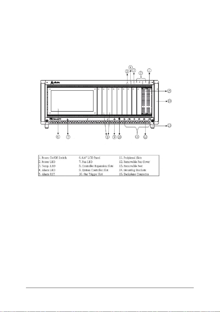
Figure 1-1 & 1-2 show some of the feature, and components of the PXIS2650 series chassis. Figure 1-1 shows the front view of the PXIS2650/2650T. Figure 1-2 shows the rear view of the PXIS-2650/2650T.
Figure 1-1 Front View of the PXIS-2650/2650T Chassis
Introduction ● 3
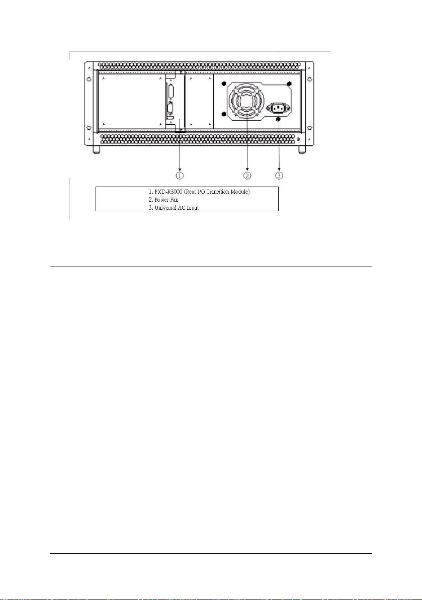
Figure 1-2 Rear View of the PXIS-2650/2650T Chassis
1.3 OEM options
The standard PXIS-2650 series chassis includes two backplanes and a
power supply unit in addition to the enclosure metal parts. The following
sections depict the standard parts used in the PXIS-2650 series.
1.3.1 Backplane
The PXIS-2650 series has 8-slot PXI backplane cBX-3008L inside. To use
redundant power users can choose the following power backplane:
cBP-3061: Backplane for one 47-pin 3U CompactPCI modular with
one ATX DC output power supply unit.
cBP-3062A: Backplane for one 47-pin 3U CompactPCI modular with
two ATX DC output power supply unit.
Please refer to the Appendix for detail specifications.
ADLINK provides customized design and manufacturing service. Please
contact an ADLINK sales representative for available backplane
configurations.
1.3.2 Power Supply Unit
PXIS-2650 series equips the APS-940XA, a 400 W modular power supply
unit that is complaint with PICMG 2.11, the ATX Power Supply
Specifications. Please refer to Appendix A.3 for detail specifications.
Various models that accommodate different AC or DC input are available.
4 ● Introduction

This makes PXIS-2650 series suitable for wide variety of applications
such as telecom signal analysis and transportation computer, which
require 24V/48V DC input power supply. Please contact a n ADLINK sales
representative for available power supply configurations.
1.3.3 Chassis Color and Logo
The standard color of PXI-2650 series is beige. ADLINK provides custom
chassis color or paint specific logo for OEM, with minimum order
requirement. Please contact us for more details.
Introduction ● 5


2
Installation
The chapter depicts the procedure of installation PXIS-2650 series chassis.
2.1 Power Budget Consideration
Prior to installing any cards into the PXIS-2650 series chassis, please
calculate the system power requirement. The power budget for every DC
power sources shall also be checked, including +5V, +3.3V, +12V, -12V
supply rail. Please refer to Appendix A.3 for the maximum usable power.
2.2 Step for Installation
Follow the step to power on the chassis.
1. Make sure the power switch is in the OFF position.
2. Plug in the AC power cord.
3. Install your system controller. Please check the ejector/in jector
handle is pushed down. Align the controller edge to the “RED”
card guide, sliding in to the rear of the chassis. Push up on the
ejector/injector handle to fully inject the card into the chassis.
Secure the screws on the module’s front panel.
4. Install peripheral mod ules if n ecessary.
5. Press the power switch on the front panel to power on the
chassis.
6. Check the LED to make sure the power input is ready. There
are four green LED indicators (3.3V, 5V, +12V, and -12V). The
four LEDs will light when power turn on.
7. Check if the system power starts, the fans under the chassis
should become operational as well.
Installation ● 7

Note: If the chassis does not power on, see Chapter 4, Troubleshooting and
Preventative Maintenance.
2.3 System monitoring
There are LEDs on the front panel for system monitoring, including
powers, temperature, and fans. Please refer to following for the detail
meaning of display status on LEDs.
System Monitoring
Power LED (Voltage : 3.3V, 5V, +12V, -12V)
o
Color: Green
o
ON while supplied
Temperature LED
o
Color: Amber
o
ON for normal condition
o
Flashes if exceeds temperature
Fan LED
o
Color: Green
o
ON while normal fan speed
o
Flashes if abnormal fan speed
Alarm LED
o
Color: Red
o
ON while normal condition
o
Flashes if alarm occurs
The Alarm Buzzer beeps continuously if any alarm occurs. When the
Alarm Buzzer beeps, users can check the LED on the front panel to find
out which kind of alarm occurs.
There is a black button labeled Alarm RST near by the Alarm LED on the
front panel. When the Alarm LED flashes and the Alarm Buzzer continues
beeping, you can push Alarm RST button to stop beeping.
Users can further refer to Chapter 4 for Troubleshooting.
8 ● Installation
 Loading...