

Page 1

EXP-ETH8
EPIC Express
TM
Add-on-Board
Technical Manual
TME-EXP-ETH8-1V3
Revision 1.3 / February 14
©LiPPERT Adlink Technology GmbH
Hans-Thoma-Str. 11
D-68163 Mannheim
http://www.adlinktech.com
Page 2

Technical Manual EXP-ETH8
LiPPERT Document: TME-EXP-ETH8-1V3 Revision 1.3
Copyright © 2009 LiPPERT Adlink Technology GmbH, All rights reserved
Contents and specifications within this manual are subject of change without notice.
Trademarks
Windows XP is a trademark of Microsoft Corporation. EPIC Express is a registered trademark of PC/104
Consortium.
All other trademarks appearing in this document are the property of their respective owners.
Page 3

Table of Contents
1 Overview 1
1.1 Introduction ................................................................................................................................. 1
Features .................................................................................................................................................................... 1
Block Diagram ........................................................................................................................................................ 2
1.2 Ordering Information ................................................................................................................ 3
EXP-ETH8 Models ................................................................................................................................................. 3
1.3 Specifications ............................................................................................................................... 4
Electrical Specifications ...................................................................................................................................... 4
Environmental Specifications ........................................................................................................................... 4
Mean Time Between Failures ........................................................................................................................... 4
1.4 Mechanical ................................................................................................................................... 5
2 Getting Started 8
2.1 Connector Locations .................................................................................................................. 8
Top .............................................................................................................................................................................. 8
Bottom ...................................................................................................................................................................... 9
2.2 Hardware Setup ........................................................................................................................ 10
2.3 Software Setup .......................................................................................................................... 10
3 Module Description 11
3.1 Gigabit Ethernet Controller .................................................................................................... 11
Ethernet Connector
............................................................................................................................................ 11
3.2 LED Indicators ........................................................................................................................... 11
3.3 PC/104-Plus Bus Connector .................................................................................................... 12
TME-EXP-ETH8-1V3 Rev 1.3 i
Page 4

3.4 PCI/104 Express Bus Interface ............................................................................................... 14
Top PCI/104-Express Connector
Bottom PCI/104-Express Connector ........................................................................................................... 14
................................................................................................................... 14
Appendix A, Contact Information A
Appendix B, Additional Information B
Appendix C, Getting Help C
Appendix D, Revision History D
Acronyms
RxD Received Data
TxD Transmitted Data
USB Universal Serial Bus
TME-EXP-ETH8-1V3 Rev 1.3 ii
Page 5

1 Overview
1.1 Introduction
The EXP-ETH8 is an Add-on Module conforming to the EPIC ExpressTM Specification.
It comprises eight independent 10/100/1000 Mb/s ports that can be easily connected to RJ45 sockets mounted
at the front of the module.
The state of link, speed and activity is show by two LEDs on every socket.
The EXP-ETH8 supports Stack-up and Stack-down to a CPU Module.
Furthermore the EXP-ETH8 uses the 5 Volt and 3.3 Volt power supplied from the PCI/104-Express connector.
All other voltages are generated on the board itself.
The EXP-ETH8 runs with Linux and Windows operation systems.
Features
MAC
Flow Control Support compliant with the 802.3x
specification
VLAN support compliant with the 802.1Q
specification
MAC address filters: perfect match unicast
multicast hash filtering, broadcast filter
Programmable host memory receive buffers and
promiscuous mode
Statistics for management
MAC loopback
PCI Express
64-bit address master support
Programmable host memory receive buffers
(256 bytes to 16 KB)
Intelligent interrupt generation features to
enhance driver performance
Descriptor ring management hardware for
transmit and receive software controlled
reset
MSI/MSI-X compatible
Configurable receive and transmit data FIFO,
programmable in 1 KB increments
TME-EXP-ETH8-1V3 Rev 1.3 Page 1 of 17
Page 6

PHY
Compliant with the 1 Gb/s IEEE 802.3 802.3u
802.3ab specifications
IEEE 802.3ab auto negotiation support
Full duplex operation at 10/100/1000 Mb/s
Half duplex at 10/100 Mb/s
Auto MDI, MDI-X crossover at all speeds
Manageability
SMBus advanced pass through interface
Block Diagram
High Performance
TCP segmentation capability with Large Send
offloading features
Support up to 256 KB TCP segmentation
(TSOv2)
Fragmented UDP checksum offload support
Split header support
Receive Side Scaling with two hardware
receive queues
9 KB jumbo frame support
32 KB packet buffer size
TME-EXP-ETH8-1V3 Rev 1.3 Page 2 of 17
Page 7

1.2 Ordering Information
EXP-ETH8 Models
Order number Description
714-0004-10 EXP-ETH8 with eight galvanic isolated 10/100/1000 MBit/s
Operating temp. range: 0°C…+60°C
814-0004-10 EXP-ETH8 with eight galvanic isolated 10/100/1000 MBit/s
Operating temp. range: -20°C…+60°C
914-0004-10 EXP-ETH8 with eight galvanic isolated 10/100/1000 MBit/s
Operating temp. range: -45°C…+85°C
TME-EXP-ETH8-1V3 Rev 1.3 Page 3 of 17
Page 8

1.3 Specifications
Electrical Specifications
Supply voltage +3.3V DC and +5 V DC (via PCI/104-Express Bus)
Rise time < 10 ms
Supply voltage tolerance ± 5% *
Power consumption maximum (with transfer on all 8 ports at the same time)
+V5S_IN: 2.2A
+V3.3S_IN: 0.4A
typical (with transfer on 4 ports at the same time)
+V5S_IN: 1.47A
+V3.3S_IN: 0.37A
minimum (with no transfer)
+V5S_IN: 0.9A
+V3.3S_IN: 0.33A
Environmental Specifications
Operating:
Temperature range 0 … 60 °C (commercial version)
-20 … 60 °C (industrial version)
-40 … 85 °C (extended version)
Temperature change max. 10K / 30 minutes
Humidity (relative) 10 … 90 % (non-condensing)
Pressure 450 … 1100 hPa
Non-Operating/Storage/Transport:
Temperature range -40 … 85 °C
Temperature change max. 10K / 30 minutes
Humidity (relative) 5 … 95 % (non-condensing)
Pressure 450 … 1100 hPa
Mean Time Between Failures
MTBF at 25°C
673.613 hours
TME-EXP-ETH8-1V3 Rev 1.3 Page 4 of 17
Page 9

1.4 Mechanical
Dimensions (L x W) 165 mm x 115 mm
Height max. 17 mm on top side above PCB
max. 12 mm on bottom side above PCB
Weight 168 g
Mounting 4 mounting holes
Board-to-Board Stacking
height
22 mm
Note: It is strongly recommend using plastic spacers instead of metal spacers to mount
the board. With metal spacers, there is a possible danger to create a short circuit
with the components located around the mounting holes.
This can damage the board!
TME-EXP-ETH8-1V3 Rev 1.3 Page 5 of 17
Page 10

TH
c
v
m
i
i
e
d
t
a
a
e
s
a
1
Me
Front
Side
hanical v
view
iew
ew
Syste
stack-up v
ew with Hurr
icane-QM57
nd heat spr
ader
Not
For detaile
TME-EXP-E
-1V3
departmen
mechanical
.
drawings or
Rev 1.3
tep files ple
se contact our support
Page 6 of
7
Page 11

Metrics on Top
TME-EXP-ETH8-1V3 Rev 1.3 Page 7 of 17
Page 12
2 Getting Started
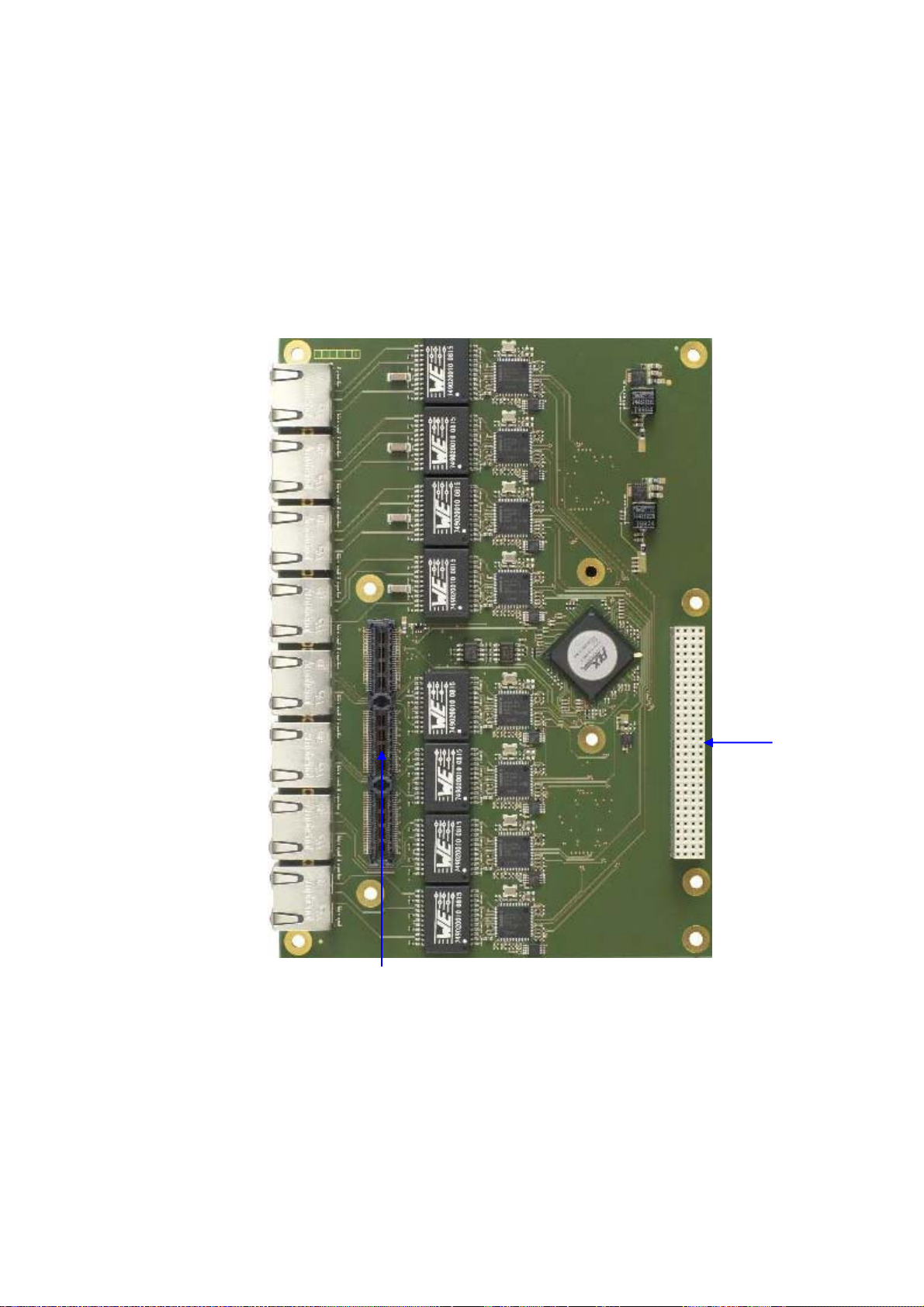
2.1 Connector Locations
Top
Port 1
X20
Port 2
X21
Port 3
X22
Port 4
X23
Port 5
PC/104
Port 6
Port 7
X26
Port 8
X27
PCIe/104 Express
TME-EXP-ETH8-1V3 Rev 1.3 Page 8 of 17
Page 13

Bottom
PC/104
PCIe/104
TME-EXP-ETH8-1V3 Rev 1.3 Page 9 of 17
Page 14

2.2 Hardware Setup
Caution Be sure to observe the EMC security measures. Make sure you are always at
Caution Do never connect or disconnect the EXP-ISO-COM8 Add-on Module with a
Be sure that your power supply is able to provide enough current to your system. An insufficient power supply
leads to an instable system.
the same potential as the module.
CPU board while that is running.
The EXP-ETH8 need an extra heat sink for standard environment temperatures from –20 °C … +60 °C as well
as the extended range of -40 °C ... +85 °C.
2.3 Software Setup
Driver packages are available for all the common operating systems:
Please contact our support department at http://askanexpert.adlinktech.com or have a look at the website
www.adlinktech.com or http://downloadcenter.intel.com for downloading the necessary drivers. Installation
guide and all necessary information is provided in the driver package.
TME-EXP-ETH8-1V3 Rev 1.3 Page 10 of 17
Page 15

3 Module Description
3.1 Gigabit Ethernet Controller
On board there are eight gigabit Ethernet controller mounted, all are from the same type INTEL 82574.
The 82574IT is a single, compact, low power component that offers a fully-integrated Gigabit Ethernet Media
Access Control (MAC) and Physical Layer (PHY) port.
The 82574 uses the PCI Express architecture.
Ethernet Connector
Connector type: RJ45
PIN Signal (Port A)
1 D1+
2 D1-
3 D2+
4 D3+
5 D3-
6 D2-
7 D4+
8 D4-
3.2 LED Indicators
Link and Activity
Link
The green LED indicates that a link
to another device has been
established.
Activity
During transmission the green LED
starts flashing.
100 Mbit/s
A green LED indicates that a
established connection uses that
data rate.
1 Gbit/s
A yellow LED indicates that a
established connection uses that
data rate.
Speed
TME-EXP-ETH8-1V3 Rev 1.3 Page 11 of 17
Page 16

3.3 PC/104-Plus Bus Connector
The PC/104-plus bus is not used on that module. The mounted connector forwards the signal through.
Pin A B C D
1 GND n.c. n.c. n.c.
2 n.c. n.c. n.c. n.c.
3 n.c. GND n.c. n.c.
4 n.c. n.c. GND n.c.
5 GND n.c. n.c. GND
6 n.c. n.c. n.c. n.c.
7 n.c. n.c. GND n.c.
8 n.c. n.c. n.c. n.c.
9 n.c. GND n.c. n.c.
10 GND n.c. n.c. n.c.
11 n.c. n.c. n.c. GND
12 n.c. n.c. GND n.c.
13 n.c. GND n.c. n.c.
14 GND n.c. n.c. n.c.
15 n.c. n.c. n.c. GND
16 n.c. n.c. GND n.c.
17 n.c. n.c. n.c. n.c.
18 n.c. GND n.c. n.c.
19 n.c. n.c. n.c. n.c.
20 GND n.c. n.c. GND
21 n.c. n.c. n.c. n.c.
22 n.c. n.c. GND n.c.
23 n.c. GND n.c. n.c.
24 GND n.c. n.c. n.c.
25 n.c. n.c. n.c. GND
TME-EXP-ETH8-1V3 Rev 1.3 Page 12 of 17
Page 17

Pin A B C D
26 n.c. n.c. GND n.c.
27 n.c. n.c. n.c. GND
28 GND n.c. n.c. n.c.
29 n.c. n.c. n.c. n.c.
30 n.c. n.c. n.c. GND
TME-EXP-ETH8-1V3 Rev 1.3 Page 13 of 17
Page 18

3.4 PCI/104 Express Bus Interface
The EXP-ETH8 uses x16 link of the PCI/104-Express bus. Which link is used depends if the board is stacked-up
or stacked -down.
On the module there is a PCI Express switch that detects the type of connection and forwards the other links
according to the specification.
The EXP-ETH8 can be used with the Hurricane-QM57.
At the Hurricane-QM57 you can stack-up one EXP-ETH8. Theoretical could be connected two EXP-ETH8, but
then they are limited to 4 Ethernet Ports at each add-on. The reason for this is the limitation of the I/O space
(and also therefore the devices) in the PCI-to-PCI bridge specification.
Top PCI/104-Express Connector
Connector Type: Samtec ASP-142781-05
Bottom PCI/104-Express Connector
Connector Type: Samtec ASP-129646-03
Pin Signal Pin Signal
1
3
5
7
9
11
13
15
17
19
21
23
25
27
29
+3.3V
USB_1+
USB_1-
GND
Pex1_1Tp
Pex1_1Tn
GND
Pex1_2 Tp
Pex1_2 Tn
GND
Pex1_1Rp
Pex1_1Rn
GND
Pex1_2 Rp
2
4
6
8
10
12
14
16
+5V
18
20
22
24
26
28
30
+3.3V
USB_0+
USB_0-
GND
Pex1_0 Tp
Pex1_0 Tn
GND
Pex1_3 Tp
Pex1_3 Tn
GND
Pex1_0 Rp
Pex1_0 Rn
GND
Pex1_3 Rp
TME-EXP-ETH8-1V3 Rev 1.3 Page 14 of 17
Page 19

31
33
35
37
39
41
43
45
47
49
51
Pex1_2 Rn
GND
Pex1_1Clkp
Pex1_1Clkn
+5V_Always
Pex1_2Clkp
Pex1_2Clkn
CPU_DIR
SMB_DAT
SMB_CLK
SMB_ALERT
32
34
36
38
40
42
44
46
48
50
52
Pex1_3 Rn
Pex1_0Clkp
Pex1_0Clkn
+5V_Always
Pex1_3Clkp
Pex1_3Clkn
PWRGOOD
Pex16_Clkp
Pex16_Clkn
GND
PSON#
TME-EXP-ETH8-1V3 Rev 1.3 Page 15 of 17
Page 20

Pin Signal Pin Signal
53
55
57
59
61
63
65
67
69
71
73
75
77
79
81
83
85
87
89
91
93
95
97
99
101
103
GND
Pex16_0T(8)p
Pex16_0T(8)n
GND
Pex16_0T(9)p
Pex16_0T(9)n
GND
Pex16_0T(10)p
Pex16_0T(10)n
GND
Pex16_0T(11)p
Pex16_0T(11)n
GND
Pex16_0T(12)p
Pex16_0T(12)n
GND
Pex16_0T(13)p
Pex16_0T(13)n
GND
Pex16_0T(14)p
Pex16_0T(14)n
GND
Pex16_0T(15)p
Pex16_0T(15)n
GND
54
56
58
60
62
64
66
68
70
72
74
76
78
+5V
80
82
84
86
88
90
92
94
96
98
100
102
104
GND
Pex16_0T(0)p
Pex16_0T(0)n
GND
Pex16_0T(1)p
Pex16_0T(1)n
GND
Pex16_0T(2)p
Pex16_0T(2)n
GND
Pex16_0T(3)p
Pex16_0T(3)n
GND
Pex16_0T(4)p
Pex16_0T(4)n
GND
Pex16_0T(5)p
Pex16_0T(5)n
GND
Pex16_0T(6)p
Pex16_0T(6)n
GND
Pex16_0T(7)p
Pex16_0T(7)n
GND
PIN Signal PIN Signal
105
107
109
111
113
115
117
119
121
123
125
GND
Pex16_0R(8)p
Pex16_0R(8)n
GND
Pex16_0R(9)p
Pex16_0R(9)n
GND
Pex16_0R(10)p
Pex16_0R(10)n
GND
106
108
110
112
114
116
+12V
118
120
122
124
126
GND
Pex16_0R(0)p
Pex16_0R(0)n
GND
Pex16_0R(1)p
Pex16_0R(1)n
GND
Pex16_0R(2)p
Pex16_0R(2)n
GND
TME-EXP-ETH8-1V3 Rev 1.3 Page 16 of 17
Page 21

127
129
131
133
135
137
139
141
143
145
147
149
151
153
155
Pex16_0R(11)p
Pex16_0R(11)n
GND
Pex16_0R(12)p
Pex16_0R(12)n
GND
Pex16_0R(13)p
Pex16_0R(13)n
GND
Pex16_0R(14)p
Pex16_0R(14)n
GND
Pex16_0R(15)p
Pex16_0R(15)n
GND
128
130
132
134
136
138
140
142
144
146
148
150
152
154
156
Pex16_0R(3)p
Pex16_0R(3)n
GND
Pex16_0R(4)p
Pex16_0R(4)n
GND
Pex16_0R(5)p
Pex16_0R(5)n
GND
Pex16_0R(6)p
Pex16_0R(6)n
GND
Pex16_0R(7)p
Pex16_0R(7)n
GND
TME-EXP-ETH8-1V3 Rev 1.3 Page 17 of 17
Page 22

Appendix A, Contact Information
Headquarters
LiPPERT ADLINK Technology GmbH
Hans-Thoma-Straße 11
68163 Mannheim
Germany
Phone +49 621 43214-0
Fax +49 621 4321430
E-mail sales: emea@adlinktech.com
Support: helpdesk@adlinktech.com
RMA: RMA.EMEA@adlinktech.com
Website http://www.adlinktech.com/rugged/index.php
TME-EXP-ETH8-1V3 Rev 1.3 Appendix A
Page 23

Appendix B, Additional Information
B.1 Additional Reading
Datasheet of the PEX8618 at http://www.plxtech.com
B.2 PCI/104 ExpressTM
A copy of the latest PCI/104 Express and can be obtained from the PC/104 Consortium's website at
www.pc104.org
TME-EXP-ETH8-1V3 Rev 1.3 Appendix B
Page 24

Appendix C, Getting Help
Should you have technical questions that are not covered by the respective manuals, please contact our
support department at http://askanexpert.adlinktech.com .
Please allow one working day for an answer.
Returning Products for Repair
To return a product to ADLINK Technology GmbH for repair, you need to get a Return Material Authorization
(RMA) number first.
Please print the RMA Request Form from http://www.adlinktech.com/lippert/rma.php
fill in the blanks and fax it to +49 621 4321430. We'll return it to you with the RMA number.
For further RMA requests use this RMA email: RMA.EMEA@adlinktech.com
Caution: Deliveries without a valid RMA number are returned to sender at his or her own cost.
TME-EXP-ETH8-1V3 Rev 1.3 Appendix C
Page 25

Appendix D, Revision History
Filename Date Edited
by
TME-EXP-ISO-COM8-R0V0.doc 2009-12-10 CS Draft
TME-EXP-ISO-COM8-R1V0.doc 2011-01-12 UW Updates for Rev1V0
TME-EXP-ISO-COM8-R1V1.doc 2011-01-19 MF 1.3 MTBF value added
2.3 Software Setup added
TME-EXP-ISO-COM8-R1V2.doc 2011-02-22 MF 1.4 mechanical dimensions corrected
Appendix A new US address
TME-EXP-ISO-COM8-R1V3.doc 2014-02-03 MF
Ch. 1.4 clarified stacking height 22m, mechanical
view added
Ch. 3.4 SAMTEC part number corrected
Change
TME-EXP-ETH8-1V3 Rev 1.3 Appendix D
 Loading...